EP1089602B1 - Elektronenbeschleuniger - Google Patents
Elektronenbeschleuniger Download PDFInfo
- Publication number
- EP1089602B1 EP1089602B1 EP99250345A EP99250345A EP1089602B1 EP 1089602 B1 EP1089602 B1 EP 1089602B1 EP 99250345 A EP99250345 A EP 99250345A EP 99250345 A EP99250345 A EP 99250345A EP 1089602 B1 EP1089602 B1 EP 1089602B1
- Authority
- EP
- European Patent Office
- Prior art keywords
- cavity
- rotation axis
- axis
- radius
- conductors
- Prior art date
- Legal status (The legal status is an assumption and is not a legal conclusion. Google has not performed a legal analysis and makes no representation as to the accuracy of the status listed.)
- Expired - Lifetime
Links
- 239000004020 conductor Substances 0.000 claims description 49
- 238000010894 electron beam technology Methods 0.000 claims description 28
- 230000005684 electric field Effects 0.000 claims description 27
- 230000001133 acceleration Effects 0.000 claims description 24
- 238000002347 injection Methods 0.000 claims description 5
- 239000007924 injection Substances 0.000 claims description 5
- 230000005672 electromagnetic field Effects 0.000 claims description 3
- 230000000694 effects Effects 0.000 description 4
- 230000008878 coupling Effects 0.000 description 2
- 238000010168 coupling process Methods 0.000 description 2
- 238000005859 coupling reaction Methods 0.000 description 2
- 230000010355 oscillation Effects 0.000 description 2
- 230000009471 action Effects 0.000 description 1
- 230000002776 aggregation Effects 0.000 description 1
- 238000004220 aggregation Methods 0.000 description 1
- 230000008901 benefit Effects 0.000 description 1
- 238000006243 chemical reaction Methods 0.000 description 1
- 238000010276 construction Methods 0.000 description 1
- 239000006185 dispersion Substances 0.000 description 1
- 229910001385 heavy metal Inorganic materials 0.000 description 1
- 238000000034 method Methods 0.000 description 1
- 230000003071 parasitic effect Effects 0.000 description 1
- 230000008569 process Effects 0.000 description 1
- 239000000243 solution Substances 0.000 description 1
- 239000000126 substance Substances 0.000 description 1
Images
Classifications
-
- H—ELECTRICITY
- H05—ELECTRIC TECHNIQUES NOT OTHERWISE PROVIDED FOR
- H05H—PLASMA TECHNIQUE; PRODUCTION OF ACCELERATED ELECTRICALLY-CHARGED PARTICLES OR OF NEUTRONS; PRODUCTION OR ACCELERATION OF NEUTRAL MOLECULAR OR ATOMIC BEAMS
- H05H13/00—Magnetic resonance accelerators; Cyclotrons
- H05H13/10—Accelerators comprising one or more linear accelerating sections and bending magnets or the like to return the charged particles in a trajectory parallel to the first accelerating section, e.g. microtrons or rhodotrons
Definitions
- the present invention relates to an electron accelerator. It is used in the irradiation of various substances either directly by electrons or by x-rays obtained by conversion on heavy metal targets.
- An electron accelerator which in general terms comprises a resonant cavity energized by a high frequency field source and the electron source able to inject electrons into the cavity. If certain phase and velocity conditions are satisfied the electrons are accelerated by the electric field troughout their passage through the cavity.
- the electron beam passes through the cavity several times,
- the apparatus then comprises an electron deflector receiving the once accelerated beam which then deflects it by approximately 180° and reinject it into the cavity for a further acceleration.
- a second deflector can again deflect the beam which has undergone two accelerations, so that it is made to pass through the cavity a third time and in this way obtains a third acceleration and so on.
- Such an apparatus is e. g. described in French Patent 15 55 723 entitled "100 MeV continuously operating electron accelerator".
- This type of accelerator suffers from the following disadvantage.
- the electron beam follows a path coinciding with the axis thereof.
- the electric field only has a single component directed along the axis.
- acceleration of the electrons takes place and there is no deflection of the beam because there is no transverse component of the electric field.
- the electron beam takes a path which is no longer directed along said axis.
- a magnetic component perpendicular to the axial component of the electric field can act on the electron beam, so that the electrons are deflected. This deflection will depend on the phase of the electromagnetic field which heads to a dispersion of the beam and consequently part will be lost on the walls of the cavity.
- this parasitic phenomenon increases during multiple passages.
- acceleration takes place in resonant cavity and after each passage the electrons are deflected outside the vavity so that they pass round the same and are re-injected into the.acceleration axis.
- the electron beam is reflected on itself and thus performs an outward and return travel along the cavity axis.
- the electron beam during this multiple passage, still follows the path for which the deflecting fields are zero (the electric field is parallel to the velocity vector of the electrons and is opposite directed).
- the advantage of this apparatus is in complete absence of the magnetic component of high frequency field at the beam accelerating area, and deflectors location unification.
- the disadvantage of this apparatus is in necessity of high rate of beam acceleration even at passing the first high frequency accelerating gap from external conductor to internal one (about 500 - 800 kV).
- the reason is that the electron velocity is to be close to that of the light for providing synchronization of the electrons travel with alternation of the polarity of the electric field in the gap between external and internal conductors. In view of this, there are observed 200 - 300 kW losses of capacity in the cavity.
- Toexee high efficiency of gaining of energy by the electrons in the first gap between external and internal conductors at the electrons travel path along the first diameter, it is nessessary to provide this apparatus with high initial energy and pulse velocity of the electron current, which is injected by the electron source.
- the present invention aims to avoid all disadvantages mentioned above.
- an electron accelerator benefitting from the effect of multiple passages through the cavity and incorporating absence of deflecting high frequency magnetic field along the electrons paths through the cavity, and which makes it possible to use low - rate of the beam accelerating along each passage through the cavity.
- the electron accelerator includes a source of electrons and a toroidal cavity, having a rotation axis.
- Said toroidal cavity is connected with a high frequency source which excites the azimuthal homogeneous distribution for electromagnetic fields in the cavity.
- the electric field component is parallel to said rotation axis of the cavity and the magnetic field component is equal to zero.
- Said source of electrons injects the electron beam into the cavity along a first axis and the beam crosses the cavity without changing the direction of motion.
- deflectors For the purpose of multiple acceleration in the cavity deflectors are placed outside the cavity and entrances and exits of the deflectors are located on axes of the beam crossing the cavity which are parallel to the rotation axis of the cavity and, different from each other, disposed on the cylindrical surface with an accelerating radius and its rotation axis identical to said rotation axis.
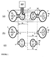
- FIG. 1(a) displays a toroidal cavity TC having two identical flat ring-shaped conductors 1 and 2 with an rotation axis A, which are symmetrically located with respect to a median plane PM, the conductor 3, closing the conductors 1 and 2 to each other from the external side and having the same rotation axis, and the conductor 4, closing the conductors 1 and 2 from the internal side and having the same rotation axis.
- This cavity TC is energized by a high frequency source SHF via the coupling loop 5.
- the cacity TC has the rotation axis A and the median plane PM perpendicular to the rotation axis A and located at the center of the distance between the conductors 1 and 2.
- the conductors 1 and 2 are symmetrically placed with respect to the median plane PM.
- the electric field E parallel to the rotation axis A of the cavity TC and with the magnetic field M, perpendicular to this rotation axis A.
- the electric field E and the magnetic field M have no rotation variation.
- FIG. 1(b) displays the part of the cavity TC, which contains the external sides of the conductors 1 and 2 and the conductor 4.
- Toroidal cavity TC inside the conductor 4 appears to be an inductivity, while the volume between the ring-shaped conductors 1 and 2 appears to be a capacity. High frequency current goes from one conductor to another via the conductor 4.
- This part of the cavity TC has resonant frequency with the magnetic field M, having only azimuthal component.
- FIG. 1(c) displays the part of the cavity TC, which contains the internal conductor 3 and the internal sides of the conductors 1 and 2.
- This part of the cavity TC has resonance frequency with the magnetic field M symmetrical with respect to the rotation axis A. If the resonance frequencies of the external and internal parts of the cavity TC coincide, then their aggregation into the cavity TC will have the same resonance frequency, and in the point of connection of the internal and external sides of the conductors 1 and 2 the high frequency currents will be absent and the magnetic field M will be equal to zero, while the electric field E between the conductors 1 and 2 will have its maximum value.
- the radius of the maximum of the electric field E between the conductors 1 and 2, absence of the magnetic component and coincidence of the resonance frequencies of the external and internal sides of the cavity TC are provided by increase of the cross-section of the cavity TC inside the conductor 4 with respect to the cross-section of the cavity TC inside the conductor 3. As far as in this case there is no magnetic field component in the cavity TC between the conductor 1 and 2 along the radius Ra, then the electron current is not subjected to to any deflection force.
- the electric field E is of the maximum value and is directed in parallel direction to the rotation axis A of the cavity TC, then the acceleration of the electrons is possible by means of multiple passages of the beam along the axis of the symmetry of the cavity TC.
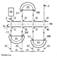
- FIG. 2 the scheme of the electron beam acceleration in the toroidal cavity TC is shown.
- FIG. 2 it is depicted the azimuthal section of the acceleration structure. This section goes through the point in which the electron beam crosses the median plane PM on the radius Ra of the electic field maximum.
- the invention operates as follows.
- the electron source ES emits an electron beam F in parallel direction to the cavity rotation axis A and perpendicular to the median plane PM along the axis A1, located on the radius Ra of the electric field maximum between the conductors 1 and 2.
- the beam F enters the cavity through the opening 10 in the conductor 1, is accelerated and leaves the cavity TC through the opening 11 in the conductor 2. Then it goes to the entrance 111 of a deflector D1 without changing the direction (without leaving axis A1).
- the deflector D1 deflects the beam F by 180° and directs the beam F through an exit 200 to the cavity TC along the axis A2 in parallel direction with respect to the cavity rotation axis A, located on the radius Ra of the maximum of the electric field E between the conductors 1 and 2.
- Azimuthal directions of the axes A2 and A1 differ by an angle ⁇ 1. While passing the cavity TC between entrance 20 and exit 21, the electron beam F is accelerated by the electric field E, if the phase conditions are fulfilled. Leaving the cavity TC through the opening 21, the electron beam F travels along the axis A2 until it reaches the entrance 211 of the deflector D2.
- the deflector D2 deflects the beam F by 180° and directs the beam F through the exit 300 to the cavity TC along the axis A3 in parallel direction with respect of the cavity rotation axis A, located on the radius Ra of the maximum- of the electric field E between the conductors 1 and 2.
- Azimuthal directions of the axes A2 and A3 differ by an angle ⁇ 2. While passing the cavity TC between entrance 30 and exit 31, the electron beam F is accelerated by the electric field E, if the phase conditions are fulfilled. While traveling along the axis A3 after leaving the cavity TC through the exit 31, the beam F is introduced to the entrance 311 of the deflector D3.
- the deflector D3 deflects the beam F by 180° and directs the beam F through the exit 400 to the cavity TC along the axis A4 in parallel direction with respect to the cavity rotation axis A, located on the radius Ra of the maximum of the electric field E between the conductors 1 and 2.
- Azimuthal directions of the axes A3 and A4 differ by an angle ⁇ 3. While passing the cavity TC between entrance 40 and exit 41, the electron beam F is accelerated by the electric field E, if the phase conditions are fulfilled. If no succeeding deflectors are installed, then the acceleration process is completed and the beam F goes along the axis A4 to destination. If succeeding deflectors are installed, the acceleration can be proceeded.
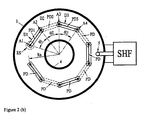
- FIG. 2 In part (b) of FIG. 2 there is depicted the median plane PM section of the accelerator on the basis of toroidal cavity TC with the electric field E parallel to the cavity rotation axis A.
- the toroidal cavity TC together with the conductors 3 and 4 is supplied by the high frequency source SHF with the energy at the frequency, equal to the resonance frequency of the cavity TC.
- the radius Ra On the radius Ra is created the maximum of tension with the electric field direction parallel to the rotation axis A and perpendicular to the median plane PM.
- the electron source ES is located outside the cavity TC and injects the beam F along the axis A1, perpendicular to the median plane PM and located on the radius Ra.
- the beam F After acceleration in the cavity TC, the beam F keeps the travel direction along the axis A1 and is introduced to the deflector D1 placed at the side of the cavity TC opposite to the electron source ES.
- the beam F is turned in the plane of the deflector PD1 by the angle 180° and is redirected to the cavity TC along the axis A2, which is parallel to the rotation axis A on the radius Ra and which differs from the axis A1 by the angle ⁇ 1. If the synchronism conditions are fulfilled, the beam F crosses the cavity TC, is accelerated and, keeping the travel along the axis A2, is introduced to the entrance of the deflector D2, placed on the opposite side with respect to the deflector D1.
- the beam F is turned in the plane of the deflector PD2 by the angle 180° an is redirected to the cavity TC along the axis A3, which is parallel to the rotation axis A on the radius Ra and which differs from the axis by the angle ⁇ 2. If the synchronism conditions are fulfilled the beam F crosses the cavity TC, is accelerated and, keeping the travel along the axis A3, is introduced to the entrance of the deflector D3, placed on the opposite side with respect to the deflector D2.
- the beam F is turned in the plane of the deflector PD3 by the angle 180° and is redirected to the cavity TC along the axis A4, which is parallel to the rotation axis A on the radius Ra and which differs from the axis A3 by the angle ⁇ 3. If the synchronism conditions are fulfilled, the beam F crosses the cavity TC and is accelerated. The succeeding deflectors are installed in the same fashion.
- the electron beam F injected by the electron source ES is accelerated at the cavity TC in the gap between the conductors 1 and 2.
- the direction of the electric field in the cavity TC must be changed to opposite.
- the direction of the electric field E must be changed to opposite once more.
- the synchronism conditions are the same for the succeeding accelerations.
- the electrons velocity is V
- c the speed of light
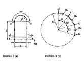
- ⁇ the length of the electron path from the median plane PM to the deflector and back
- Beam focusing is necessary to keep a certain beam dimensions in the vicinity of the central trajectory. Focusing elements are placed outside the cavity between the cavity and the deflector. It is possible to use magnetic quadrupole lenses for this purpose. However, the better solution is to use solenoids with magnetic field, directed along the beam trajectory.
- Focusing effect of the solenoids is proportional to the length of the magnetic field action and square of the magnetic field value. In the relativistic case it is inverse proportional to the square of the electrons velocity. As far as at solenoids regular location the mean beam dimension slightly depends on the focusing effect of each of the solenoids, accuracy of the choice of this effect for the solenoids is low.
- Electric quality of the cavity is usually characterized by effective shunt resistance Rsh as the ratio of the square of the gained energy of the electrons at- one passage through the cavity (in eV) to the energy dissipated in the conductors.
- the energy dissipated in the cavity is reverse proportional to the square of the number of the beam passages through the cavity. That is why it is reasonable to use large number of passages, but it necessitates increase of the energy supply of the deflectors.
Landscapes
- Physics & Mathematics (AREA)
- Engineering & Computer Science (AREA)
- Plasma & Fusion (AREA)
- Spectroscopy & Molecular Physics (AREA)
- Particle Accelerators (AREA)
Claims (4)
- Elektronenbeschleuniger, der eine Elektronenquelle (ES) und einen torusförmigen Hohlraum (TC) mit einer Rotationsachse (A) umfaßt, wobei der torusförmige Hohlraum (TC) mit einer Hochfrequenzquelle (SHF) verbunden ist, welche die azimutal homogene Verteilung der elektromagnetischen Felder (E) im Hohlraum (TC) anregt; beim Beschleunigungsradius (Ra) des Hohlraumes (TC) ist die elektrische Feldkomponente (E) parallel zur Rotationsachse (A) des Hohlraumes (TC) ausgerichtet, die magnetische Feldkomponente (M) ist gleich null und die Elektronenquelle (ES) injiziert den Elektronenstrahl (F) in den Hohlraum (TC) in Richtung einer ersten Achse (A1), und der Strahl (F) durchquert den Hohlraum (TC), ohne die Richtung seiner Bewegung zu ändern, und zum Zwecke einer mehrmaligen Beschleunigung im Hohlraum (TC) sind außerhalb des Hohlraumes (TC) Deflektoren (D1, D2, D3) angeordnet, und Eintrittsstellen (111, 211, 311) und Austrittsstellen (200, 300, 400) der Deflektoren (D1, D2, D3) sind auf Achsen (A1, A2, A3) des Strahls (F), der den Hohlraum (TC) durchquert, angeordnet, die parallel zur Rotationsachse (A) des Hohlraumes (TC) ausgerichtet und auf der zylindrischen Oberfläche im Beschleunigungsradius (Ra) unterschiedlich zueinander verteilt sind, dessen Rotationsachse identisch mit der Rotationsachse (A) ist.
- Elektronenbeschleuniger nach Anspruch 1, dadurch gekennzeichnet, dass der torusförmige Hohlraum (TC) zwei flache, ringförmige Leiter (1, 2) mit der Rotationsachse (A) umfaßt, die in Bezug auf die rechtwinklig zur Rotationsachse (A) liegende Medianebene (PM) symmetrisch verlaufen, und dass die Enden der Leiter (1, 2) mit dem größeren Radius durch einen äußeren Leiter (4) miteinander verbunden sind, der dieselbe Rotationsachse (A) hat, und dass die Enden der Leiter (1, 2) mit dem kleineren Radius durch einen inneren Leiter (3) miteinander verbunden sind, der dieselbe Rotationsachse (A) hat, und dass die Leiter (1, 2, 3, 4) den torusförmigen Hohlraum (TC) bilden, und dass die Abmessungen der äußeren und inneren Leiter (3, 4) so sind, dass das elektrische Feld (E) zwischen den ringförmigen Leitern (1, 2) beim Beschleunigungsradius (Ra) parallel zur Rotationsachse (A) und rechtwinklig zur Medianebene (PM) verläuft und in Richtung zur Oberfläche der ringförmigen Leiter (1, 2) gerichtet ist, und dass die magnetische Feldkomponente (M) gleich null ist.
- Elektronenbeschleuniger nach Anspruch 1 oder 2, dadurch gekennzeichnet, dass der Elektronenstrahl (F), der in den Hohlraum (TC) in Richtung einer ersten Achse (A1) injiziert wird, die parallel zur Rotationsachse (A) liegt und im Beschleunigungsradius (Ra) angeordnet ist, auf seiner Bahn zwischen den ringförmigen Leitern (1, 2) in Richtung der ersten Achse (A1) einer ersten Beschleunigung unterworfen wird, den Hohlraum (TC) verläßt und seine Bewegungsrichtung in Richtung der ersten Achse (A1) beibehält bis er abgelenkt wird, wozu außerhalb des Hohlraumes (TC) ein erster Deflektor (D1) angeordnet ist, der den Elektronenstrahl (F) empfängt, nachdem dieser während der Bewegung entlang der ersten Achse (A1) beschleunigt wurde und den Strahl (F) für eine erneute Injektion in den Hohlraum (TC) in Richtung einer zweiten Achse (A2) ablenkt, die parallel zur Rotationsachse (A) des Hohlraumes (TC) gerichtet und im Beschleunigungsradius (Ra) angeordnet ist und die von der ersten Achse (A1) verschieden ist, und dass der Elektronenstrahl (F) auf der Bahn durch den Hohlraum (TC) zwischen den ringförmigen Leitern (1, 2) einer zweiten Beschleunigung unterworfen wird, und dass der Elektronenstrahl (F) sich nach der zweiten Beschleunigung in Richtung der zweiten Achse (A2) bis zum zweiten Deflektor (D2) bewegt, der außerhalb des Hohlraumes (TC) angeordnet ist, und dass der zweite Deflektor (D2) den Elektronenstrahl (F) empfängt und den Elektronenstrahl (F) für die nachfolgende erneute Injektion in den Hohlraum (TC) in Richtung einer dritten Achse (A3) ablenkt, die parallel zur Rotationsachse (A) des Hohlraumes (TC) gerichtet und im Beschleunigungsradius (Ra) angeordnet ist und die von den ersten und zweiten Achsen (A1, A2) verschieden ist, und dass aufeinanderfolgende Deflektoren auf die gleiche Art und Weise angeordnet sind, so dass die Richtungen der Bewegung des Elektronenstrahls (F) durch den Hohlraum (TC) und zwischen den aufeinanderfolgenden Deflektoren auf Achsen liegen, die parallel zur Rotationsachse (A) verlaufen und voneinander verschieden und im Beschleunigungsradius (Ra) angeordnet sind.
- Elektronenbeschleuniger nach einem der vorhergehenden Ansprüche, wobei fokussierende Elemente zwischen dem Hohlraum (TC) und den Deflektoren (D1, PD1; D2, PD2; D3, PD3; PD) installiert sind.
Priority Applications (6)
| Application Number | Priority Date | Filing Date | Title |
|---|---|---|---|
| AT99250345T ATE259577T1 (de) | 1999-09-28 | 1999-09-28 | Elektronenbeschleuniger |
| EP99250345A EP1089602B1 (de) | 1999-09-28 | 1999-09-28 | Elektronenbeschleuniger |
| DE69914750T DE69914750T2 (de) | 1999-09-28 | 1999-09-28 | Elektronenbeschleuniger |
| AU76598/00A AU7659800A (en) | 1999-09-28 | 2000-09-27 | Electron accelerator |
| PCT/EP2000/009449 WO2001024592A1 (en) | 1999-09-28 | 2000-09-27 | Electron accelerator |
| ARP000105133A AR025904A1 (es) | 1999-09-28 | 2000-09-28 | Un acelerador de electrones. |
Applications Claiming Priority (1)
| Application Number | Priority Date | Filing Date | Title |
|---|---|---|---|
| EP99250345A EP1089602B1 (de) | 1999-09-28 | 1999-09-28 | Elektronenbeschleuniger |
Publications (2)
| Publication Number | Publication Date |
|---|---|
| EP1089602A1 EP1089602A1 (de) | 2001-04-04 |
| EP1089602B1 true EP1089602B1 (de) | 2004-02-11 |
Family
ID=8241157
Family Applications (1)
| Application Number | Title | Priority Date | Filing Date |
|---|---|---|---|
| EP99250345A Expired - Lifetime EP1089602B1 (de) | 1999-09-28 | 1999-09-28 | Elektronenbeschleuniger |
Country Status (6)
| Country | Link |
|---|---|
| EP (1) | EP1089602B1 (de) |
| AR (1) | AR025904A1 (de) |
| AT (1) | ATE259577T1 (de) |
| AU (1) | AU7659800A (de) |
| DE (1) | DE69914750T2 (de) |
| WO (1) | WO2001024592A1 (de) |
Families Citing this family (2)
| Publication number | Priority date | Publication date | Assignee | Title |
|---|---|---|---|---|
| FR2815810B1 (fr) * | 2000-10-20 | 2003-11-28 | Thomson Tubes Electroniques | Accelerateur d'electrons compact a cavite resonante |
| WO2008138998A1 (en) * | 2007-05-16 | 2008-11-20 | Ion Beam Applications S.A. | Electron accelerator and device using same |
Family Cites Families (2)
| Publication number | Priority date | Publication date | Assignee | Title |
|---|---|---|---|---|
| FR1555723A (de) * | 1967-11-21 | 1969-01-31 | ||
| FR2684512B1 (fr) * | 1991-11-28 | 1997-04-18 | Commissariat Energie Atomique | Accelerateur d'electrons a cavite resonante. |
-
1999
- 1999-09-28 EP EP99250345A patent/EP1089602B1/de not_active Expired - Lifetime
- 1999-09-28 DE DE69914750T patent/DE69914750T2/de not_active Expired - Lifetime
- 1999-09-28 AT AT99250345T patent/ATE259577T1/de not_active IP Right Cessation
-
2000
- 2000-09-27 AU AU76598/00A patent/AU7659800A/en not_active Abandoned
- 2000-09-27 WO PCT/EP2000/009449 patent/WO2001024592A1/en not_active Ceased
- 2000-09-28 AR ARP000105133A patent/AR025904A1/es active IP Right Grant
Also Published As
| Publication number | Publication date |
|---|---|
| DE69914750T2 (de) | 2004-12-02 |
| WO2001024592A1 (en) | 2001-04-05 |
| ATE259577T1 (de) | 2004-02-15 |
| EP1089602A1 (de) | 2001-04-04 |
| AU7659800A (en) | 2001-04-30 |
| AR025904A1 (es) | 2002-12-18 |
| DE69914750D1 (de) | 2004-03-18 |
Similar Documents
| Publication | Publication Date | Title |
|---|---|---|
| US5107221A (en) | Electron accelerator with coaxial cavity | |
| US7898193B2 (en) | Slot resonance coupled standing wave linear particle accelerator | |
| US5216377A (en) | Apparatus for accumulating charged particles with high speed pulse electromagnet | |
| JPH0668989A (ja) | 改良された入射空洞構造を有する線形加速器 | |
| US4672615A (en) | Ion and electron beam steering and focussing system | |
| JP3736343B2 (ja) | 直流電子ビーム加速装置およびその直流電子ビーム加速方法 | |
| Tantawi et al. | Distributed coupling accelerator structures: A new paradigm for high gradient linacs | |
| US5095486A (en) | Free electron laser with improved electronic accelerator | |
| EP1089602B1 (de) | Elektronenbeschleuniger | |
| US4870368A (en) | Spiral line accelerator | |
| JP3857096B2 (ja) | 荷電粒子ビームの出射装置及び円形加速器並びに円形加速器システム | |
| US5300861A (en) | Method in a pulsed accelerator for accelerating a magnetized rotating plasma | |
| JP2869084B2 (ja) | 適当な入射電圧に対して電子捕獲率が高い自己集束式キャビティを備える線形加速器 | |
| US3611166A (en) | Accelerator for relativistic electrons | |
| JP4056448B2 (ja) | 複数ビーム同時加速空洞 | |
| US4563615A (en) | Ultra high frequency radio electric wave generators | |
| WO1997038436A1 (en) | Single-beam and multiple-beam klystrons using periodic permanent magnets for electron beam focusing | |
| US5384794A (en) | Undulator where the wavelength of the radiation light is changed by varying the frequency of the electromagnetic wave travelling in the waveguide | |
| JP7497870B2 (ja) | 荷電粒子加速装置及び荷電粒子加速方法 | |
| US5982787A (en) | Rippled beam free electron laser amplifier | |
| CA2787794C (en) | Multirhodotron | |
| JPH06103640B2 (ja) | 荷電ビ−ム装置 | |
| JP2001015299A (ja) | 多重通過型加速器、加速空胴、及びこれらを用いた電子線・x線照射処理装置 | |
| JP2001052896A (ja) | 粒子加速・蓄積装置 | |
| JPH01217900A (ja) | 加速器 |
Legal Events
| Date | Code | Title | Description |
|---|---|---|---|
| PUAI | Public reference made under article 153(3) epc to a published international application that has entered the european phase |
Free format text: ORIGINAL CODE: 0009012 |
|
| AK | Designated contracting states |
Kind code of ref document: A1 Designated state(s): AT BE CH CY DE DK ES FI FR GB GR IE IT LI LU MC NL PT SE |
|
| AX | Request for extension of the european patent |
Free format text: AL;LT;LV;MK;RO;SI |
|
| 17P | Request for examination filed |
Effective date: 20010921 |
|
| AKX | Designation fees paid |
Free format text: AT BE CH CY DE DK ES FI FR GB GR IE IT LI LU MC NL PT SE |
|
| GRAP | Despatch of communication of intention to grant a patent |
Free format text: ORIGINAL CODE: EPIDOSNIGR1 |
|
| GRAS | Grant fee paid |
Free format text: ORIGINAL CODE: EPIDOSNIGR3 |
|
| GRAA | (expected) grant |
Free format text: ORIGINAL CODE: 0009210 |
|
| AK | Designated contracting states |
Kind code of ref document: B1 Designated state(s): AT BE CH CY DE DK ES FI FR GB GR IE IT LI LU MC NL PT SE |
|
| PG25 | Lapsed in a contracting state [announced via postgrant information from national office to epo] |
Ref country code: NL Free format text: LAPSE BECAUSE OF FAILURE TO SUBMIT A TRANSLATION OF THE DESCRIPTION OR TO PAY THE FEE WITHIN THE PRESCRIBED TIME-LIMIT Effective date: 20040211 Ref country code: IT Free format text: LAPSE BECAUSE OF FAILURE TO SUBMIT A TRANSLATION OF THE DESCRIPTION OR TO PAY THE FEE WITHIN THE PRESCRIBED TIME-LIMIT;WARNING: LAPSES OF ITALIAN PATENTS WITH EFFECTIVE DATE BEFORE 2007 MAY HAVE OCCURRED AT ANY TIME BEFORE 2007. THE CORRECT EFFECTIVE DATE MAY BE DIFFERENT FROM THE ONE RECORDED. Effective date: 20040211 Ref country code: FI Free format text: LAPSE BECAUSE OF FAILURE TO SUBMIT A TRANSLATION OF THE DESCRIPTION OR TO PAY THE FEE WITHIN THE PRESCRIBED TIME-LIMIT Effective date: 20040211 Ref country code: CY Free format text: LAPSE BECAUSE OF FAILURE TO SUBMIT A TRANSLATION OF THE DESCRIPTION OR TO PAY THE FEE WITHIN THE PRESCRIBED TIME-LIMIT Effective date: 20040211 Ref country code: AT Free format text: LAPSE BECAUSE OF FAILURE TO SUBMIT A TRANSLATION OF THE DESCRIPTION OR TO PAY THE FEE WITHIN THE PRESCRIBED TIME-LIMIT Effective date: 20040211 |
|
| REG | Reference to a national code |
Ref country code: GB Ref legal event code: FG4D |
|
| REG | Reference to a national code |
Ref country code: CH Ref legal event code: EP |
|
| REG | Reference to a national code |
Ref country code: IE Ref legal event code: FG4D |
|
| REF | Corresponds to: |
Ref document number: 69914750 Country of ref document: DE Date of ref document: 20040318 Kind code of ref document: P |
|
| PG25 | Lapsed in a contracting state [announced via postgrant information from national office to epo] |
Ref country code: SE Free format text: LAPSE BECAUSE OF FAILURE TO SUBMIT A TRANSLATION OF THE DESCRIPTION OR TO PAY THE FEE WITHIN THE PRESCRIBED TIME-LIMIT Effective date: 20040511 Ref country code: GR Free format text: LAPSE BECAUSE OF FAILURE TO SUBMIT A TRANSLATION OF THE DESCRIPTION OR TO PAY THE FEE WITHIN THE PRESCRIBED TIME-LIMIT Effective date: 20040511 Ref country code: DK Free format text: LAPSE BECAUSE OF FAILURE TO SUBMIT A TRANSLATION OF THE DESCRIPTION OR TO PAY THE FEE WITHIN THE PRESCRIBED TIME-LIMIT Effective date: 20040511 |
|
| PG25 | Lapsed in a contracting state [announced via postgrant information from national office to epo] |
Ref country code: ES Free format text: LAPSE BECAUSE OF FAILURE TO SUBMIT A TRANSLATION OF THE DESCRIPTION OR TO PAY THE FEE WITHIN THE PRESCRIBED TIME-LIMIT Effective date: 20040522 |
|
| REG | Reference to a national code |
Ref country code: CH Ref legal event code: AEN Free format text: DAS PATENT IST AUF GRUND DES WEITERBEHANDLUNGSANTRAGS VOM 05.07.2004 REAKTIVIERT WORDEN. |
|
| NLV1 | Nl: lapsed or annulled due to failure to fulfill the requirements of art. 29p and 29m of the patents act | ||
| PG25 | Lapsed in a contracting state [announced via postgrant information from national office to epo] |
Ref country code: LU Free format text: LAPSE BECAUSE OF NON-PAYMENT OF DUE FEES Effective date: 20040928 Ref country code: IE Free format text: LAPSE BECAUSE OF NON-PAYMENT OF DUE FEES Effective date: 20040928 |
|
| PG25 | Lapsed in a contracting state [announced via postgrant information from national office to epo] |
Ref country code: MC Free format text: LAPSE BECAUSE OF NON-PAYMENT OF DUE FEES Effective date: 20040930 |
|
| ET | Fr: translation filed | ||
| PLBE | No opposition filed within time limit |
Free format text: ORIGINAL CODE: 0009261 |
|
| STAA | Information on the status of an ep patent application or granted ep patent |
Free format text: STATUS: NO OPPOSITION FILED WITHIN TIME LIMIT |
|
| 26N | No opposition filed |
Effective date: 20041112 |
|
| REG | Reference to a national code |
Ref country code: CH Ref legal event code: PL |
|
| REG | Reference to a national code |
Ref country code: CH Ref legal event code: AEN Free format text: DAS PATENT IST AUFGRUND DES WEITERBEHANDLUNGSANTRAGS VOM 11.05.2005 REAKTIVIERT WORDEN. |
|
| REG | Reference to a national code |
Ref country code: IE Ref legal event code: MM4A |
|
| PG25 | Lapsed in a contracting state [announced via postgrant information from national office to epo] |
Ref country code: LI Free format text: LAPSE BECAUSE OF NON-PAYMENT OF DUE FEES Effective date: 20050930 |
|
| REG | Reference to a national code |
Ref country code: CH Ref legal event code: PL |
|
| REG | Reference to a national code |
Ref country code: CH Ref legal event code: AEN Free format text: DAS PATENT IST AUFGRUND DES WEITERBEHANDLUNGSANTRAGS VOM 15.05.2006 REAKTIVIERT WORDEN. |
|
| REG | Reference to a national code |
Ref country code: CH Ref legal event code: PL |
|
| REG | Reference to a national code |
Ref country code: CH Ref legal event code: AEN Free format text: DAS PATENT IST AUFGRUND DES WEITERBEHANDLUNGSANTRAGS VOM 14.06.2007 REAKTIVIERT WORDEN. |
|
| PG25 | Lapsed in a contracting state [announced via postgrant information from national office to epo] |
Ref country code: PT Free format text: LAPSE BECAUSE OF NON-PAYMENT OF DUE FEES Effective date: 20040711 |
|
| PGFP | Annual fee paid to national office [announced via postgrant information from national office to epo] |
Ref country code: CH Payment date: 20071001 Year of fee payment: 9 |
|
| REG | Reference to a national code |
Ref country code: CH Ref legal event code: PL |
|
| PG25 | Lapsed in a contracting state [announced via postgrant information from national office to epo] |
Ref country code: LI Free format text: LAPSE BECAUSE OF NON-PAYMENT OF DUE FEES Effective date: 20080930 Ref country code: CH Free format text: LAPSE BECAUSE OF NON-PAYMENT OF DUE FEES Effective date: 20080930 |
|
| PGFP | Annual fee paid to national office [announced via postgrant information from national office to epo] |
Ref country code: FR Payment date: 20100930 Year of fee payment: 12 |
|
| PGFP | Annual fee paid to national office [announced via postgrant information from national office to epo] |
Ref country code: GB Payment date: 20100924 Year of fee payment: 12 |
|
| PGFP | Annual fee paid to national office [announced via postgrant information from national office to epo] |
Ref country code: DE Payment date: 20101130 Year of fee payment: 12 Ref country code: BE Payment date: 20100921 Year of fee payment: 12 |
|
| BERE | Be: lapsed |
Owner name: HANS *WALISCHMILLER G.M.B.H. Effective date: 20110930 |
|
| GBPC | Gb: european patent ceased through non-payment of renewal fee |
Effective date: 20110928 |
|
| REG | Reference to a national code |
Ref country code: FR Ref legal event code: ST Effective date: 20120531 |
|
| PG25 | Lapsed in a contracting state [announced via postgrant information from national office to epo] |
Ref country code: BE Free format text: LAPSE BECAUSE OF NON-PAYMENT OF DUE FEES Effective date: 20110930 |
|
| PG25 | Lapsed in a contracting state [announced via postgrant information from national office to epo] |
Ref country code: DE Free format text: LAPSE BECAUSE OF NON-PAYMENT OF DUE FEES Effective date: 20120403 |
|
| REG | Reference to a national code |
Ref country code: DE Ref legal event code: R119 Ref document number: 69914750 Country of ref document: DE Effective date: 20120403 |
|
| PG25 | Lapsed in a contracting state [announced via postgrant information from national office to epo] |
Ref country code: FR Free format text: LAPSE BECAUSE OF NON-PAYMENT OF DUE FEES Effective date: 20110930 Ref country code: GB Free format text: LAPSE BECAUSE OF NON-PAYMENT OF DUE FEES Effective date: 20110928 |