EP1089239B1 - Integriertes Motordiagnosesystem - Google Patents
Integriertes Motordiagnosesystem Download PDFInfo
- Publication number
- EP1089239B1 EP1089239B1 EP00306462A EP00306462A EP1089239B1 EP 1089239 B1 EP1089239 B1 EP 1089239B1 EP 00306462 A EP00306462 A EP 00306462A EP 00306462 A EP00306462 A EP 00306462A EP 1089239 B1 EP1089239 B1 EP 1089239B1
- Authority
- EP
- European Patent Office
- Prior art keywords
- fault
- data
- aircraft
- mission data
- diagnostic system
- Prior art date
- Legal status (The legal status is an assumption and is not a legal conclusion. Google has not performed a legal analysis and makes no representation as to the accuracy of the status listed.)
- Expired - Lifetime
Links
- 230000004044 response Effects 0.000 claims abstract description 10
- 238000000034 method Methods 0.000 claims description 19
- 238000004590 computer program Methods 0.000 claims description 6
- 230000003213 activating effect Effects 0.000 claims description 3
- 238000001514 detection method Methods 0.000 description 9
- 238000010200 validation analysis Methods 0.000 description 5
- 238000012545 processing Methods 0.000 description 4
- 238000010586 diagram Methods 0.000 description 2
- 238000012423 maintenance Methods 0.000 description 2
- 238000012544 monitoring process Methods 0.000 description 2
- 238000005070 sampling Methods 0.000 description 2
- 238000012546 transfer Methods 0.000 description 2
- 230000000007 visual effect Effects 0.000 description 2
- 230000004913 activation Effects 0.000 description 1
- 230000005540 biological transmission Effects 0.000 description 1
- 230000003111 delayed effect Effects 0.000 description 1
- 230000006866 deterioration Effects 0.000 description 1
- 238000002405 diagnostic procedure Methods 0.000 description 1
- 230000000694 effects Effects 0.000 description 1
- 238000009429 electrical wiring Methods 0.000 description 1
- 230000005670 electromagnetic radiation Effects 0.000 description 1
- 239000000835 fiber Substances 0.000 description 1
- 239000000446 fuel Substances 0.000 description 1
- 238000009434 installation Methods 0.000 description 1
- 238000012360 testing method Methods 0.000 description 1
Images


Classifications
-
- G—PHYSICS
- G07—CHECKING-DEVICES
- G07C—TIME OR ATTENDANCE REGISTERS; REGISTERING OR INDICATING THE WORKING OF MACHINES; GENERATING RANDOM NUMBERS; VOTING OR LOTTERY APPARATUS; ARRANGEMENTS, SYSTEMS OR APPARATUS FOR CHECKING NOT PROVIDED FOR ELSEWHERE
- G07C3/00—Registering or indicating the condition or the working of machines or other apparatus, other than vehicles
-
- F—MECHANICAL ENGINEERING; LIGHTING; HEATING; WEAPONS; BLASTING
- F02—COMBUSTION ENGINES; HOT-GAS OR COMBUSTION-PRODUCT ENGINE PLANTS
- F02C—GAS-TURBINE PLANTS; AIR INTAKES FOR JET-PROPULSION PLANTS; CONTROLLING FUEL SUPPLY IN AIR-BREATHING JET-PROPULSION PLANTS
- F02C9/00—Controlling gas-turbine plants; Controlling fuel supply in air- breathing jet-propulsion plants
-
- F—MECHANICAL ENGINEERING; LIGHTING; HEATING; WEAPONS; BLASTING
- F05—INDEXING SCHEMES RELATING TO ENGINES OR PUMPS IN VARIOUS SUBCLASSES OF CLASSES F01-F04
- F05D—INDEXING SCHEME FOR ASPECTS RELATING TO NON-POSITIVE-DISPLACEMENT MACHINES OR ENGINES, GAS-TURBINES OR JET-PROPULSION PLANTS
- F05D2260/00—Function
- F05D2260/80—Diagnostics
Definitions
- the invention relates generally to an aircraft engine diagnostic system embedded in the aircraft for detecting faults during take off and does not require external systems to detect a fault.
- the U.S. Air Force currently downloads mission data from each F-16 at the end of each day. The data is transferred to portable data transfer devices and subsequently downloaded into ground support systems. This data is then compared to previous mission data and performance faults are determined based on trend data.
- the support equipment infrastructure has been unreliable and expensive to maintain.
- This system requires significant maintenance manpower resources and exposes the engine and aircraft to the potential of undetected trend faults due to ground system equipment related problems.
- the existing system would not enunciate a trend fault until the end of the day which could be after multiple missions.
- the support equipment In a deployed scenario, the support equipment must be transported to the remote site to determine if a performance fault exists.
- US 3,731,070 discloses a gas turbine engine analyzer.
- US 5,050,081 discloses a method and system for monitoring and displaying engine performance parameters.
- An exemplary embodiment of the invention is an aircraft engine diagnostic system embedded in the aircraft for detecting faults during take off comprising the features of claim 1.
- Another exemplary embodiment of the invention is a method for detecting faults during take off in an aircraft having an engine diagnostic system embedded in the aircraft, the method comprising the steps of claim 4.
- FIG.1 is a block diagram of an embedded engine diagnostic system in an exemplary embodiment of the invention.
- the embedded engine diagnostic system includes a processor 2 which executes the diagnostic process described herein with reference to FIGS. 2A and 2B .
- Processor 2 may be implemented using existing microprocessors.
- Sensors 4 are coupled to the processor 2 and provide values for engine parameters (such as fuel rate) and/or aircraft parameters (such as Mach number) to the processor 2.
- a program memory 10 is a non-volatile memory which contains the program to be executed by the processor 2.
- the program memory 10 may be electrically programmable (such as an EEPROM) so that the program to be executed by processor 2 can be updated.
- a data memory 12 stores current mission data and prior mission data for a plurality of prior missions which are used to detect faults as described herein.
- the data memory 12 may be implemented using known non-volatile memory.
- a communications port 8 is coupled to processor 2 and is used to upload configuration data (e.g., aircraft type, engine type, etc.) or download configuration data and mission data from data memory 12.
- the communications port 8 may use existing communications protocols such as RS232.
- the communications port 8 is preferably accessible from the exterior of the aircraft.
- the processor Upon detection of a fault, the processor activates a fault indicator 6.
- the fault indicator 6 may include an indicator visible by the pilot (e.g., an LED in the cockpit) and an indicator visible from the exterior of the aircraft (e.g., an LED or mechanical device at the wheel well strut). Providing a direct indication of a fault on the exterior of the aircraft eliminates the need to download mission data to ground systems to detect a fault and provides fault detection for each mission.
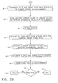
- FIGS. 2A and 2B depict a flowchart of the processing performed by the embedded engine diagnostic system according to the invention.
- the embedded engine diagnostic system is programmed to detect faults during take-off.
- the process begins at step 20 where the aircraft speed is monitored to detect when the aircraft is within a velocity range.
- the velocity range is about Mach 0.22 to about Mach 0.33.
- the aircraft is in the take-off process and the engine is in a stable state and up to normal operating temperature.
- the embedded engine diagnostic system sequentially acquires a plurality of data records (e.g., four). Acquiring data under uniform conditions (e.g., within a predetermined velocity range) results in more accurate detection of faults.
- the multiple data records are separated by a sampling interval (e.g., 1 ⁇ 2 second).
- Each of the data records contains values indicative of parameters including engine parameters or aircraft parameters.
- An exemplary data record is shown in FIG. 3 which depicts the parameters sensed by sensors 4 and the values for each parameter.
- the process may pause for a period of time (e.g., three minutes) prior to proceeding to step 22.
- the embedded engine diagnostic system will generate a fault indication in the cockpit through fault indicator 6. Activation of the fault indicator may be delayed until the aircraft completes takeoff.
- the value processing routine is initiated to preprocess the sensor data acquired at step 20 prior to detection of faults.
- a validation routine is performed on the values in each of the data records.
- the validation routine may apply various tests to determine if the sampled data is appropriate for detecting faults. The goal is to confirm that the values in each data record are suitable for detecting faults. Because the embedded engine diagnostic system compares current mission data to prior mission data to generate faults, the current mission data is validated to ensure an accurate comparison.
- An exemplary validation is confirming that a value for a parameter has remained constant over the multiple samplings. For example, for accurate comparison to past missions, it may be necessary that the throttle position remain constant for all data records.
- Another exemplary validation is confirming that values for a parameter are within a predetermined range. If the values in the data records fail validation, the process is ended.
- a single average data record is generated at step 26.
- the average data record which contains an average value, derived from the multiple data records, for each parameter.
- the average values are converted into the appropriate engineering units if necessary.
- the sensors 4 may generate signals in terms of abstract units (e.g., voltage, counts per second, etc.).
- these abstract units are converted to engineering units (e.g., pressure, speed, etc.) due to the fact that the fault detection in an exemplary embodiment of the invention is performed based on engineering units.
- baseline differential values are determined for each parameter in the average data record.
- a baseline differential value indicates the difference between an average value from a sensor and a predicted new engine, baseline value (e.g., predicted from a model or other source).
- the baseline differential value can be represented in a variety of ways including a difference (i.e., Xsensed - Xpredicted) or a ratio (i.e., Xsensed / Xpredicted).
- step 34 it is determined whether the engine is new. Designating an engine as new sets a mission history counter kpts to zero indicating that no prior mission data stored in memory is to be used in detecting faults.
- An engine may be classified as new upon a variety of conditions including initial installation, maintenance, retrofit, etc.
- Prior mission data is saved as the new engine completes missions. Until prior mission data is available, the embedded engine diagnostic system detects a limited number of faults that do not require prior mission data for detection.
- the kpts counter is incremented and prior mission data is incremented to create space for the current mission data.
- the prior mission data is stored in a first-in, first-out manner in which mission data beyond the thirty past missions is removed from memory.
- the current mission data i.e., average values and baseline differential values
- the embedded engine diagnostic system initiates a fault detection process as shown at step 40.
- a step 42 all available prior mission data (i.e., prior average values and prior baseline differential values for each parameter) is retrieved.
- the current average values and current baseline differential values for each parameter are retrieved.
- This prior mission data and current mission data are processed to detect faults in step 46.
- a variety of faults can be detected by the embedded engine diagnostic system in response to current mission data and prior mission data. For example, a leak in a compressor line is detected if the compressor bleed pressure drops by more than 25 psi for two consecutive missions. Flow path deterioration is detected if the turbine exit temperature (T4B) increases faster than a predetermined rate. It is understood that a variety of faults may be detected and the invention is not limited to the examples disclosed herein.
- FIG. 4 depicts the detection of faults based on baseline differential values as claimed in the present invention.
- FIG. 4 depicts baseline differential values (shown as a difference between the average value and the predicted new engine, baseline value) versus mission number for turbine exit temperature (DT4B). As shown in FIG. 4 , the baseline differential value DT4B varies over missions.
- One technique used for detecting a fault is computing the slope of the baseline differential value plot. A large slope may indicate a fault.
- Another technique used for detecting a fault is computing the slopes of both the T4B and corrected operating point (PHI) baseline differential value plots. A large slope on both indicates a higher probability of a real fault.
- Other known not claimed fault criteria may be applied to detect faults such as an average value exceeding a threshold.
- Other known not claimed techniques may be used to detect faults based on the mission data. Existing techniques to reduce the occurrence of false fault indications may also be used.
- fault data indicative of the absence or presence of a fault is stored in the data memory 12.
- An exemplary technique for recording the occurrence of a fault is to store a one or zero in a memory location corresponding to a fault. If a one is stored in the memory location, this indicates that the corresponding fault was detected.
- the stored fault data is examined to determine the existence of a fault. Step 50 may perform a logical OR operation on the values in the fault memory locations so that any one fault will result in activating the fault indicator 6. If a fault is detected, the fault indicator 6 is activated at step 52, otherwise the routine exits at step 54.
- the fault indicator 6 may include a visual indicator in the cockpit for the pilot (e.g., an LED) and a visual indicator which is visible from the outside of the aircraft (e.g., an LED or mechanical device).
- a visual indicator in the cockpit for the pilot e.g., an LED
- a visual indicator which is visible from the outside of the aircraft e.g., an LED or mechanical device.
- the specific cause of the fault can be detected directly next to the aircraft by using a data transfer and display device (e.g., a portable computer).
- the embedded engine diagnostic system eliminates the need to download data from each aircraft each day.
- the embedded engine diagnostic system also provides continuous monitoring of faults throughout each mission and is not degraded by ground system equipment failures.
- the present invention can be embodied in the form of computer-implemented processes and apparatuses for practicing those processes.
- the present invention can also be embodied in the form of computer program code containing instructions embodied in tangible media, such as floppy diskettes, CD ROMs, hard drives, or any other computer-readable storage medium, wherein, when the computer program code is loaded into and executed by a computer, the computer becomes an apparatus for practicing the invention.
- the present invention can also be embodied in the form of computer program code, for example, whether stored in a storage medium, loaded into and/or executed by a computer, or transmitted over some transmission medium, such as over electrical wiring or cabling, through fiber optics, or via electromagnetic radiation, wherein, when the computer program code is loaded into and executed by a computer, the computer becomes an apparatus for practicing the invention.
- computer program code segments configure the microprocessor to create specific logic circuits.
Landscapes
- Engineering & Computer Science (AREA)
- Chemical & Material Sciences (AREA)
- Combustion & Propulsion (AREA)
- General Physics & Mathematics (AREA)
- General Engineering & Computer Science (AREA)
- Physics & Mathematics (AREA)
- Mechanical Engineering (AREA)
- Combined Controls Of Internal Combustion Engines (AREA)
- Testing Of Devices, Machine Parts, Or Other Structures Thereof (AREA)
- Lubrication Of Internal Combustion Engines (AREA)
- Testing Of Engines (AREA)
- Control Of Turbines (AREA)
- Valve-Gear Or Valve Arrangements (AREA)
- Valve Device For Special Equipments (AREA)
- Electrical Control Of Air Or Fuel Supplied To Internal-Combustion Engine (AREA)
Claims (6)
- Flugzeugtriebwerksdiagnosesystem, das in dem Flugzeug zur Detektion von Fehlern während des Startvorgangs eingebaut ist, aufweisend:mehrere Sensoren (4), wobei einer von den mehreren Sensoren einen Geschwindigkeitssensor enthält, der einen die Flugzeuggeschwindigkeit anzeigenden Geschwindigkeitswert erzeugt;einen Datenspeicher (12);einen Prozessor (2), der mit den Sensoren verbunden ist, wobei der Prozessor Daten des aktuellen Einsatzes in dem Datenspeicher speichert, wenn der Geschwindigkeitswert innerhalb eines Geschwindigkeitsbereichs von Mach 0,22 bis Mach 0,33 liegt, wobei die Daten des aktuellen Einsatzes Werte für Parameter und Grundlinien-Differenzwerte für die Parameter enthalten, und wobei der Fehler ermittelt wird, indem die Steigung der Grundlinien-Differenzwerte berechnet wird, wobei eine große Steigung das Vorliegen des Fehlers anzeigt; undeine Fehleranzeigevorrichtung (6), die von außerhalb des Flugzeugs sichtbar ist;wobei der Prozessor das Vorliegen oder Fehlen eines Fehlers in Reaktion auf die Daten des aktuellen Einsatzes detektiert; in dem Datenspeicher Fehlerdaten speichert, die das Vorliegen oder Fehlen eines Fehlers anzeigen; die gespeicherten Fehlerdaten prüft, um das Vorliegen eines Fehlers zu ermitteln; und die Fehleranzeigevorrichtung in Reaktion auf das Vorliegen eines Fehlers aktiviert.
- Triebwerksdiagnosesystem nach Anspruch 1, wobei die Parameter Flugzeugparameter und Triebwerksparameter beinhalten, und wobei die Werte Durchschnittswerte beinhalten.
- Triebwerksdiagnosesystem nach Anspruch 1, wobei:der Datenspeicher Daten früherer Einsätze enthält; undder Prozessor das Vorliegen oder Fehlen eines Fehlers in Reaktion auf die Daten des aktuellen Einsatzes und die Daten früherer Einsätze detektiert.
- Verfahren zum Detektieren von Fehlern während eines Startvorgangs in einem Flugzeug mit einem in dem Flugzeug eingebauten Triebwerksdiagnosesystem, wobei das Verfahren die Schritte aufweist:Ermitteln (20), wenn sich das Flugzeug innerhalb eines Geschwindigkeitsbereichs von Mach 0,22 bis Mach 0,33 befindet, der Daten des aktuellen Einsatzes, die Werte für Parameter und Grundlinien-Differenzwerte für die Parameter beinhalten, und wobei der Fehler ermittelt wird, indem die Steigung der Grundlinien-Differenzwerte berechnet wird, wobei eine große Steigung das Vorliegen des Fehlers anzeigt;Erzielen (20) aktueller Daten des Einsatzes in Reaktion darauf, dass die Flugzeuggeschwindigkeit innerhalb des Geschwindigkeitsbereiches liegt;Detektieren (40) des Vorliegens oder Fehlens eines Fehlers in Reaktion auf Daten des aktuellen Einsatzes;Speichern von Fehlerdaten in einem Datenspeicher, die das Vorliegen oder Fehlen eines Fehlers anzeigen;Prüfen der gespeicherten Fehlerdaten, um das Vorliegen eines Fehler zu ermitteln; undAktivieren (52) einer Fehleranzeigevorrichtung in Reaktion auf das Vorliegen eines Fehlers, wobei die Fehleranzeigevorrichtung von außerhalb des Flugzeugs sichtbar ist.
- Verfahren nach Anspruch 4, ferner mit dem Schritt:Speichern von Daten früherer Einsätze; wobei die Detektion des Vorliegens oder Fehlens eines Fehlers in Reaktion auf die Daten des aktuellen Einsatzes und der Daten früherer Einsätze erfolgt.
- Speichermedium, das mit einem maschinenlesbaren Computerprogrammcode codiert ist, um Fehler in einem Flugzeug mit einem Triebwerksdiagnosesystem zu diagnostizieren, wobei das Speichermedium Anweisungen enthält, um einen Computer zu veranlassen das Verfahren der Ansprüche 4 oder 5 zu implementieren.
Applications Claiming Priority (2)
| Application Number | Priority Date | Filing Date | Title |
|---|---|---|---|
| US410238 | 1982-08-23 | ||
| US09/410,238 US6292723B1 (en) | 1999-09-30 | 1999-09-30 | Embedded engine diagnostic system |
Publications (3)
| Publication Number | Publication Date |
|---|---|
| EP1089239A2 EP1089239A2 (de) | 2001-04-04 |
| EP1089239A3 EP1089239A3 (de) | 2004-06-16 |
| EP1089239B1 true EP1089239B1 (de) | 2009-10-07 |
Family
ID=23623860
Family Applications (1)
| Application Number | Title | Priority Date | Filing Date |
|---|---|---|---|
| EP00306462A Expired - Lifetime EP1089239B1 (de) | 1999-09-30 | 2000-07-28 | Integriertes Motordiagnosesystem |
Country Status (7)
| Country | Link |
|---|---|
| US (1) | US6292723B1 (de) |
| EP (1) | EP1089239B1 (de) |
| JP (1) | JP4482206B2 (de) |
| AT (1) | ATE445206T1 (de) |
| DE (1) | DE60043089D1 (de) |
| ES (1) | ES2331944T3 (de) |
| IL (1) | IL137521A (de) |
Families Citing this family (35)
| Publication number | Priority date | Publication date | Assignee | Title |
|---|---|---|---|---|
| SG97893A1 (en) * | 2000-06-29 | 2003-08-20 | Singapore Tech Aerospace Ltd | A method of monitoring and displaying health performance of an aircraft engine |
| JP2003182473A (ja) * | 2001-12-18 | 2003-07-03 | Fuji Heavy Ind Ltd | 車両用表示装置の自己診断装置 |
| US7415243B2 (en) | 2003-03-27 | 2008-08-19 | Honda Giken Kogyo Kabushiki Kaisha | System, method and computer program product for receiving data from a satellite radio network |
| US8041779B2 (en) | 2003-12-15 | 2011-10-18 | Honda Motor Co., Ltd. | Method and system for facilitating the exchange of information between a vehicle and a remote location |
| US7818380B2 (en) | 2003-12-15 | 2010-10-19 | Honda Motor Co., Ltd. | Method and system for broadcasting safety messages to a vehicle |
| US7849149B2 (en) | 2004-04-06 | 2010-12-07 | Honda Motor Co., Ltd. | Method and system for controlling the exchange of vehicle related messages |
| US7518530B2 (en) | 2004-07-19 | 2009-04-14 | Honda Motor Co., Ltd. | Method and system for broadcasting audio and visual display messages to a vehicle |
| US7643788B2 (en) | 2004-09-22 | 2010-01-05 | Honda Motor Co., Ltd. | Method and system for broadcasting data messages to a vehicle |
| US7280941B2 (en) * | 2004-12-29 | 2007-10-09 | General Electric Company | Method and apparatus for in-situ detection and isolation of aircraft engine faults |
| US7562049B2 (en) | 2005-03-29 | 2009-07-14 | Honda Motor Co., Ltd. | Payment system and method for data broadcasted from a remote location to vehicles |
| US7949330B2 (en) | 2005-08-25 | 2011-05-24 | Honda Motor Co., Ltd. | System and method for providing weather warnings and alerts |
| US7690565B2 (en) * | 2006-06-30 | 2010-04-06 | Caterpillar Inc. | Method and system for inspecting machines |
| US7819312B2 (en) * | 2006-06-30 | 2010-10-26 | Caterpillar Inc | Method and system for operating machines |
| US7677452B2 (en) * | 2006-06-30 | 2010-03-16 | Caterpillar Inc. | Method and system for providing signatures for machines |
| US8565998B2 (en) * | 2006-11-27 | 2013-10-22 | United Technologies Corporation | Gas turbine engine having on-engine data storage device |
| US7668653B2 (en) | 2007-05-31 | 2010-02-23 | Honda Motor Co., Ltd. | System and method for selectively filtering and providing event program information |
| RU2348911C1 (ru) * | 2007-06-21 | 2009-03-10 | Федеральное государственное унитарное предприятие "Центральный институт авиационного моторостроения имени П.И. Баранова" | Способ диагностики газотурбинных двигателей при попадании посторонних предметов на их вход |
| US8099308B2 (en) | 2007-10-02 | 2012-01-17 | Honda Motor Co., Ltd. | Method and system for vehicle service appointments based on diagnostic trouble codes |
| GB0722319D0 (en) | 2007-11-14 | 2007-12-27 | Rolls Royce Plc | Component monitoring arrangement |
| US8131509B2 (en) * | 2008-03-23 | 2012-03-06 | United Technologies Corporation | Method of system design for failure detectability |
| US20090326754A1 (en) * | 2008-06-30 | 2009-12-31 | Honeywell International Inc. | Systems and methods for engine diagnosis using wavelet transformations |
| FR2946023B1 (fr) * | 2009-06-02 | 2014-11-28 | Airbus France | Procede et dispositif de traitement de pannes |
| US8135804B2 (en) | 2009-07-07 | 2012-03-13 | Honda Motor Co., Ltd. | Method for scheduling and rescheduling vehicle service appointments |
| US8862433B2 (en) | 2010-05-18 | 2014-10-14 | United Technologies Corporation | Partitioning of turbomachine faults |
| US8494889B2 (en) | 2011-06-14 | 2013-07-23 | International Business Machines Corporation | Optimized maintenance schedules based on smart city maintenance profiles |
| CN102320382A (zh) * | 2011-07-07 | 2012-01-18 | 中国国际航空股份有限公司 | 飞机性能检测方法 |
| GB2513133B (en) | 2013-04-16 | 2015-07-08 | Ge Aviat Systems Ltd | Methods for predicting a speed brake system fault |
| GB2513132B (en) * | 2013-04-16 | 2015-05-27 | Ge Aviat Systems Ltd | Method for predicting a bleed air system fault |
| FR3009396B1 (fr) | 2013-07-31 | 2017-03-17 | Airbus Operations Sas | Procede et programme d'ordinateur d'aide a la maintenance d'equipements d'un aeronef |
| FR3011105B1 (fr) * | 2013-09-20 | 2017-01-27 | Airbus Operations Sas | Procede d'identification d'un equipement defaillant dans un aeronef. |
| JP6164573B2 (ja) * | 2015-05-19 | 2017-07-19 | 株式会社アドテックス | 無人飛翔体及びそのための制御システム |
| AT517689B1 (de) * | 2015-11-11 | 2017-04-15 | Avl List Gmbh | Verfahren zum Erstellen eines Prüfversuchs |
| US10592749B2 (en) | 2016-11-14 | 2020-03-17 | General Electric Company | Systems and methods for analyzing turns at an airport |
| US10834336B2 (en) | 2018-01-29 | 2020-11-10 | Ge Aviation Systems Llc | Thermal imaging of aircraft |
| US11107307B2 (en) * | 2018-05-01 | 2021-08-31 | Ford Global Technologies, Llc | Systems and methods for probabilistic on-board diagnostics |
Family Cites Families (10)
| Publication number | Priority date | Publication date | Assignee | Title |
|---|---|---|---|---|
| US3731070A (en) * | 1971-04-27 | 1973-05-01 | United Aircraft Corp | Gas turbine engine analyzer |
| US4215412A (en) * | 1978-07-13 | 1980-07-29 | The Boeing Company | Real time performance monitoring of gas turbine engines |
| GB2128569B (en) * | 1982-10-22 | 1985-12-24 | British Aerospace | Aircraft maintenance data terminal |
| US4625280A (en) * | 1982-12-28 | 1986-11-25 | United Technologies Corporation | Sectional distress isolating electrostatic engine diagnostics |
| US4587614A (en) * | 1982-12-28 | 1986-05-06 | United Technologies Corporation | System fault detection in electrostatic flow diagnostics |
| US5050081A (en) | 1988-11-14 | 1991-09-17 | The United States Of America As Represented By The Administrator Of The National Aeronautics And Space Administration | Method and system for monitoring and displaying engine performance parameters |
| US5070458A (en) * | 1989-03-31 | 1991-12-03 | Honeywell Inc. | Method of analyzing and predicting both airplane and engine performance characteristics |
| US5018069A (en) | 1989-07-13 | 1991-05-21 | Howell Instruments, Inc. | Reference system and method for diagnosing aircraft engine conditions |
| US5408412A (en) | 1992-04-09 | 1995-04-18 | United Technologies Corporation | Engine fault diagnostic system |
| US5951611A (en) | 1996-11-18 | 1999-09-14 | General Electric Company | Diagnostic trend analysis |
-
1999
- 1999-09-30 US US09/410,238 patent/US6292723B1/en not_active Expired - Lifetime
-
2000
- 2000-07-26 IL IL13752100A patent/IL137521A/en not_active IP Right Cessation
- 2000-07-28 AT AT00306462T patent/ATE445206T1/de not_active IP Right Cessation
- 2000-07-28 ES ES00306462T patent/ES2331944T3/es not_active Expired - Lifetime
- 2000-07-28 DE DE60043089T patent/DE60043089D1/de not_active Expired - Lifetime
- 2000-07-28 EP EP00306462A patent/EP1089239B1/de not_active Expired - Lifetime
- 2000-07-28 JP JP2000228021A patent/JP4482206B2/ja not_active Expired - Fee Related
Also Published As
| Publication number | Publication date |
|---|---|
| IL137521A0 (en) | 2001-07-24 |
| IL137521A (en) | 2004-07-25 |
| ATE445206T1 (de) | 2009-10-15 |
| DE60043089D1 (de) | 2009-11-19 |
| EP1089239A3 (de) | 2004-06-16 |
| EP1089239A2 (de) | 2001-04-04 |
| JP4482206B2 (ja) | 2010-06-16 |
| ES2331944T3 (es) | 2010-01-21 |
| US6292723B1 (en) | 2001-09-18 |
| JP2001206295A (ja) | 2001-07-31 |
Similar Documents
| Publication | Publication Date | Title |
|---|---|---|
| EP1089239B1 (de) | Integriertes Motordiagnosesystem | |
| US7369932B2 (en) | System and method for turbine engine fault detection using discrete event system modeling | |
| US8528317B2 (en) | Method and system for detecting the ingestion of an object by an aircraft turbine engine during a mission | |
| EP1661100B1 (de) | Verfahren und systeme zur erkennung von vereisungsbedingungen | |
| EP1630633B1 (de) | System zur Überwachung einer Gasturbine | |
| US6868325B2 (en) | Transient fault detection system and method using Hidden Markov Models | |
| US8744651B2 (en) | Method of determining a maneuver performed by an aircraft | |
| CN100489699C (zh) | 检测紧急传感器失效的方法 | |
| EP1722072A2 (de) | Verfahren und Vorrichtung zur Bestimmung der Lebensdauer von einem Element einer Maschine | |
| US20130211768A1 (en) | Monitoring system for an engine test bench | |
| US10174863B2 (en) | Method for monitoring a valve of an aircraft engine | |
| US8869603B2 (en) | Debris detection in turbomachinery and gas turbine engines | |
| EP3401749A1 (de) | Fehlererkennung mit bereichen mit hochauflösung | |
| Fisher | Gas path debris monitoring-a 21/sup st/century PHM tool | |
| US10551818B2 (en) | Fault detection methods and systems | |
| US7249287B2 (en) | Methods and apparatus for providing alarm notification | |
| US4218879A (en) | Overspeed protection device | |
| RU2817575C1 (ru) | Способ контроля теплового состояния электронного регулятора газотурбинного двигателя | |
| CN118302598B (zh) | 从发动机数据检测涡轮机上的侧风 | |
| US12539982B2 (en) | Method for prognostic health monitoring assessment of aircraft-based angle of attack (AoA) sensors | |
| EP4332708A1 (de) | Motorsteuerungssystem und verfahren mit sensortraining mit künstlicher intelligenz | |
| EP3683642B1 (de) | Verfahren zur messung der ermüdung von mechanischen komponenten eines flugzeuges | |
| DESIGN | Q17!» | |
| Broede et al. | INCIDENT MONITORING-GENERAL REOUIREMENTS | |
| EP3311277A2 (de) | Systeme und verfahren zur diagnose von entlüftungsventilen eines turbotriebwerks |
Legal Events
| Date | Code | Title | Description |
|---|---|---|---|
| PUAI | Public reference made under article 153(3) epc to a published international application that has entered the european phase |
Free format text: ORIGINAL CODE: 0009012 |
|
| AK | Designated contracting states |
Kind code of ref document: A2 Designated state(s): AT BE CH CY DE DK ES FI FR GB GR IE IT LI LU MC NL PT SE |
|
| AX | Request for extension of the european patent |
Free format text: AL;LT;LV;MK;RO;SI |
|
| PUAL | Search report despatched |
Free format text: ORIGINAL CODE: 0009013 |
|
| AK | Designated contracting states |
Kind code of ref document: A3 Designated state(s): AT BE CH CY DE DK ES FI FR GB GR IE IT LI LU MC NL PT SE |
|
| AX | Request for extension of the european patent |
Extension state: AL LT LV MK RO SI |
|
| RIC1 | Information provided on ipc code assigned before grant |
Ipc: 7B 64D 45/00 B Ipc: 7G 07C 3/00 A |
|
| 17P | Request for examination filed |
Effective date: 20041216 |
|
| AKX | Designation fees paid |
Designated state(s): AT BE CH CY DE DK ES FI FR GB GR IE IT LI LU MC NL PT SE |
|
| APBN | Date of receipt of notice of appeal recorded |
Free format text: ORIGINAL CODE: EPIDOSNNOA2E |
|
| APBR | Date of receipt of statement of grounds of appeal recorded |
Free format text: ORIGINAL CODE: EPIDOSNNOA3E |
|
| APBV | Interlocutory revision of appeal recorded |
Free format text: ORIGINAL CODE: EPIDOSNIRAPE |
|
| GRAP | Despatch of communication of intention to grant a patent |
Free format text: ORIGINAL CODE: EPIDOSNIGR1 |
|
| GRAS | Grant fee paid |
Free format text: ORIGINAL CODE: EPIDOSNIGR3 |
|
| GRAA | (expected) grant |
Free format text: ORIGINAL CODE: 0009210 |
|
| AK | Designated contracting states |
Kind code of ref document: B1 Designated state(s): AT BE CH CY DE DK ES FI FR GB GR IE IT LI LU MC NL PT SE |
|
| REG | Reference to a national code |
Ref country code: GB Ref legal event code: FG4D |
|
| REG | Reference to a national code |
Ref country code: CH Ref legal event code: EP |
|
| REG | Reference to a national code |
Ref country code: IE Ref legal event code: FG4D |
|
| REF | Corresponds to: |
Ref document number: 60043089 Country of ref document: DE Date of ref document: 20091119 Kind code of ref document: P |
|
| REG | Reference to a national code |
Ref country code: ES Ref legal event code: FG2A Ref document number: 2331944 Country of ref document: ES Kind code of ref document: T3 |
|
| NLV1 | Nl: lapsed or annulled due to failure to fulfill the requirements of art. 29p and 29m of the patents act | ||
| PG25 | Lapsed in a contracting state [announced via postgrant information from national office to epo] |
Ref country code: PT Free format text: LAPSE BECAUSE OF FAILURE TO SUBMIT A TRANSLATION OF THE DESCRIPTION OR TO PAY THE FEE WITHIN THE PRESCRIBED TIME-LIMIT Effective date: 20100208 Ref country code: FI Free format text: LAPSE BECAUSE OF FAILURE TO SUBMIT A TRANSLATION OF THE DESCRIPTION OR TO PAY THE FEE WITHIN THE PRESCRIBED TIME-LIMIT Effective date: 20091007 Ref country code: SE Free format text: LAPSE BECAUSE OF FAILURE TO SUBMIT A TRANSLATION OF THE DESCRIPTION OR TO PAY THE FEE WITHIN THE PRESCRIBED TIME-LIMIT Effective date: 20091007 |
|
| PG25 | Lapsed in a contracting state [announced via postgrant information from national office to epo] |
Ref country code: BE Free format text: LAPSE BECAUSE OF FAILURE TO SUBMIT A TRANSLATION OF THE DESCRIPTION OR TO PAY THE FEE WITHIN THE PRESCRIBED TIME-LIMIT Effective date: 20091007 Ref country code: AT Free format text: LAPSE BECAUSE OF FAILURE TO SUBMIT A TRANSLATION OF THE DESCRIPTION OR TO PAY THE FEE WITHIN THE PRESCRIBED TIME-LIMIT Effective date: 20091007 |
|
| PG25 | Lapsed in a contracting state [announced via postgrant information from national office to epo] |
Ref country code: NL Free format text: LAPSE BECAUSE OF FAILURE TO SUBMIT A TRANSLATION OF THE DESCRIPTION OR TO PAY THE FEE WITHIN THE PRESCRIBED TIME-LIMIT Effective date: 20091007 Ref country code: DK Free format text: LAPSE BECAUSE OF FAILURE TO SUBMIT A TRANSLATION OF THE DESCRIPTION OR TO PAY THE FEE WITHIN THE PRESCRIBED TIME-LIMIT Effective date: 20091007 |
|
| PLBE | No opposition filed within time limit |
Free format text: ORIGINAL CODE: 0009261 |
|
| STAA | Information on the status of an ep patent application or granted ep patent |
Free format text: STATUS: NO OPPOSITION FILED WITHIN TIME LIMIT |
|
| 26N | No opposition filed |
Effective date: 20100708 |
|
| PG25 | Lapsed in a contracting state [announced via postgrant information from national office to epo] |
Ref country code: GR Free format text: LAPSE BECAUSE OF FAILURE TO SUBMIT A TRANSLATION OF THE DESCRIPTION OR TO PAY THE FEE WITHIN THE PRESCRIBED TIME-LIMIT Effective date: 20100108 |
|
| PG25 | Lapsed in a contracting state [announced via postgrant information from national office to epo] |
Ref country code: MC Free format text: LAPSE BECAUSE OF NON-PAYMENT OF DUE FEES Effective date: 20100731 |
|
| REG | Reference to a national code |
Ref country code: CH Ref legal event code: PL |
|
| PG25 | Lapsed in a contracting state [announced via postgrant information from national office to epo] |
Ref country code: CH Free format text: LAPSE BECAUSE OF NON-PAYMENT OF DUE FEES Effective date: 20100731 Ref country code: LI Free format text: LAPSE BECAUSE OF NON-PAYMENT OF DUE FEES Effective date: 20100731 |
|
| PG25 | Lapsed in a contracting state [announced via postgrant information from national office to epo] |
Ref country code: IE Free format text: LAPSE BECAUSE OF NON-PAYMENT OF DUE FEES Effective date: 20100728 |
|
| PG25 | Lapsed in a contracting state [announced via postgrant information from national office to epo] |
Ref country code: CY Free format text: LAPSE BECAUSE OF FAILURE TO SUBMIT A TRANSLATION OF THE DESCRIPTION OR TO PAY THE FEE WITHIN THE PRESCRIBED TIME-LIMIT Effective date: 20091007 |
|
| PG25 | Lapsed in a contracting state [announced via postgrant information from national office to epo] |
Ref country code: LU Free format text: LAPSE BECAUSE OF NON-PAYMENT OF DUE FEES Effective date: 20100728 |
|
| REG | Reference to a national code |
Ref country code: FR Ref legal event code: PLFP Year of fee payment: 17 |
|
| PGFP | Annual fee paid to national office [announced via postgrant information from national office to epo] |
Ref country code: IT Payment date: 20160722 Year of fee payment: 17 Ref country code: GB Payment date: 20160727 Year of fee payment: 17 Ref country code: DE Payment date: 20160726 Year of fee payment: 17 |
|
| PGFP | Annual fee paid to national office [announced via postgrant information from national office to epo] |
Ref country code: FR Payment date: 20160726 Year of fee payment: 17 |
|
| PGFP | Annual fee paid to national office [announced via postgrant information from national office to epo] |
Ref country code: ES Payment date: 20160726 Year of fee payment: 17 |
|
| REG | Reference to a national code |
Ref country code: DE Ref legal event code: R119 Ref document number: 60043089 Country of ref document: DE |
|
| GBPC | Gb: european patent ceased through non-payment of renewal fee |
Effective date: 20170728 |
|
| REG | Reference to a national code |
Ref country code: FR Ref legal event code: ST Effective date: 20180330 |
|
| PG25 | Lapsed in a contracting state [announced via postgrant information from national office to epo] |
Ref country code: GB Free format text: LAPSE BECAUSE OF NON-PAYMENT OF DUE FEES Effective date: 20170728 Ref country code: DE Free format text: LAPSE BECAUSE OF NON-PAYMENT OF DUE FEES Effective date: 20180201 |
|
| PG25 | Lapsed in a contracting state [announced via postgrant information from national office to epo] |
Ref country code: FR Free format text: LAPSE BECAUSE OF NON-PAYMENT OF DUE FEES Effective date: 20170731 |
|
| PG25 | Lapsed in a contracting state [announced via postgrant information from national office to epo] |
Ref country code: IT Free format text: LAPSE BECAUSE OF NON-PAYMENT OF DUE FEES Effective date: 20170728 |
|
| REG | Reference to a national code |
Ref country code: ES Ref legal event code: FD2A Effective date: 20181029 |
|
| PG25 | Lapsed in a contracting state [announced via postgrant information from national office to epo] |
Ref country code: ES Free format text: LAPSE BECAUSE OF NON-PAYMENT OF DUE FEES Effective date: 20170729 |