EP1089036B1 - A reflector having a complex surface for an illumination device of a vehicle - Google Patents
A reflector having a complex surface for an illumination device of a vehicle Download PDFInfo
- Publication number
- EP1089036B1 EP1089036B1 EP99830615A EP99830615A EP1089036B1 EP 1089036 B1 EP1089036 B1 EP 1089036B1 EP 99830615 A EP99830615 A EP 99830615A EP 99830615 A EP99830615 A EP 99830615A EP 1089036 B1 EP1089036 B1 EP 1089036B1
- Authority
- EP
- European Patent Office
- Prior art keywords
- reflector
- elementary
- plane
- sides
- complex
- Prior art date
- Legal status (The legal status is an assumption and is not a legal conclusion. Google has not performed a legal analysis and makes no representation as to the accuracy of the status listed.)
- Revoked
Links
Images



Classifications
-
- F—MECHANICAL ENGINEERING; LIGHTING; HEATING; WEAPONS; BLASTING
- F21—LIGHTING
- F21V—FUNCTIONAL FEATURES OR DETAILS OF LIGHTING DEVICES OR SYSTEMS THEREOF; STRUCTURAL COMBINATIONS OF LIGHTING DEVICES WITH OTHER ARTICLES, NOT OTHERWISE PROVIDED FOR
- F21V7/00—Reflectors for light sources
- F21V7/04—Optical design
- F21V7/09—Optical design with a combination of different curvatures
-
- F—MECHANICAL ENGINEERING; LIGHTING; HEATING; WEAPONS; BLASTING
- F21—LIGHTING
- F21S—NON-PORTABLE LIGHTING DEVICES; SYSTEMS THEREOF; VEHICLE LIGHTING DEVICES SPECIALLY ADAPTED FOR VEHICLE EXTERIORS
- F21S41/00—Illuminating devices specially adapted for vehicle exteriors, e.g. headlamps
- F21S41/30—Illuminating devices specially adapted for vehicle exteriors, e.g. headlamps characterised by reflectors
- F21S41/32—Optical layout thereof
- F21S41/33—Multi-surface reflectors, e.g. reflectors with facets or reflectors with portions of different curvature
- F21S41/337—Multi-surface reflectors, e.g. reflectors with facets or reflectors with portions of different curvature the reflector having a structured surface, e.g. with facets or corrugations
-
- F—MECHANICAL ENGINEERING; LIGHTING; HEATING; WEAPONS; BLASTING
- F21—LIGHTING
- F21S—NON-PORTABLE LIGHTING DEVICES; SYSTEMS THEREOF; VEHICLE LIGHTING DEVICES SPECIALLY ADAPTED FOR VEHICLE EXTERIORS
- F21S43/00—Signalling devices specially adapted for vehicle exteriors, e.g. brake lamps, direction indicator lights or reversing lights
- F21S43/30—Signalling devices specially adapted for vehicle exteriors, e.g. brake lamps, direction indicator lights or reversing lights characterised by reflectors
Definitions
- the present invention relates to a reflector having a complex surface for an illumination device of a vehicle; the reflector of the invention has reflecting surfaces of a new concept which make is possible to obtain, with respect to known configurations, improved photometric performance together with new aesthetic aspects, achieving this within extremely restricted dimensions.
- illumination devices of vehicles generally comprise a light source the beam of which is suitably directed and modified by a reflector which gives the beam the desired optical characteristics for each specific function.
- a reflector which gives the beam the desired optical characteristics for each specific function.
- the use of the so-called “complex" surfaces has been widely used to date, being formed by different portions each having their own shape or geometry.
- Figures 1 and 2 are, respectively, a front view and a sectional view (taken on the line II-II of Figure 1) of a reflector 1a of the type having a known complex surface configuration.
- the reflector 1a has a complex reflecting surface 2 with a predetermined optical axis 3 and is intended, in use, to be mounted on an associated illumination device of the vehicle in such a way that the optical axis 3 is substantially parallel to the motion plane on which the vehicle moves, schematically represented by the broken line 4 in Figure 1 (which represents the motion plane).
- the complex reflecting surface 2 is constituted by a plurality of sectors 5 of square shape (or rectangular in a variant which is also known) lying adjacent one another and mutually joined along respective adjacent sides: the reflector 1a is mounted on the vehicle in such a way that each of the square or rectangular elementary reflecting surfaces has a first pair of opposite sides parallel to the motion plane on which the vehicle moves, that is to the ground, and a second pair of opposite sides orthogonal thereto.
- a vehicle illumination device according to the preamble of claim 1 is known from US 1670837 A, and comprises a head lamp reflector with flat elementary sectors of polygonal shape.
- Reflectors having complex surfaces of the type briefly outlined here have the disadvantage of providing relatively poor photometric performance: in particular, the luminous intensity is relatively low with respect to the luminous power emitted by the source.
- the invention which relates to a device according to claim 1. It comprises a reflector having a complex surface for an illumination device of a vehicle, the reflector having a base surface with predetermined optical axis and a complex reflecting surface with an optical axis substantially coinciding with the said optical axis of the base surface, the said complex reflecting surface comprising a plurality of elementary sectors of predetermined shape supporting on the said base surface and provided with respective elementary reflecting surfaces, the said elementary sectors being of polygonal form and being positioned adjacent one another and mutually connected along respective adjacent sides to constitute the said complex reflecting surface, the reflector being mountable upon the said illumination device with the said optical axis substantially parallel to or convergent with a surface on which the vehicle moves.
- the said elementary sectors are of polygonal form with a number of sides equal to four; said elementary sectors are orientated in such a way that the said sides are not parallel to the said motion plane but have a predetermined inclination with respect thereto, and they have curved convex surfaces.
- the reflector according to the invention while being simple and economical to produce and of extremely limited dimensions, has characteristics of particularly high luminous intensity, greater than conventional reflectors of comparable dimensions, and moreover makes it possible to achieve new aesthetic aspect of particular effect.
- a reflector 1 for an illumination device (known and not illustrated for simplicity) of a vehicle, in particular a motor vehicle, has a complex reflecting surface 2 with a predetermined optical axis 3: the reflector 1 is intended, in use, to be mounted on an associated illumination device of the vehicle in such a way that the optical axis 3 lies substantially parallel to or convergent to a motion plane on which the vehicle moves, schematically represented by the broken line 4 in Figure 1 (representing the plane of advance).
- the reflector 1 can be shaped in any way and the complex reflecting surface 2 can consequentially have a different shape: in any case, it is possible to identify a base surface 2' which represents the general form of the reflector 1' the base surface 2' can be a surface of revolution or translation which can be described with a relatively simple equation, but can also be one which cannot be described in simple mathematical terms.
- the base surface 2' has a curvature and predetermined concavity and moreover has an optical axis substantially coincident with the optical axis 3 of the complex reflecting surface 2.
- the reflector 1 comprises a plurality of elementary sectors 5 of predetermined shape, provided with respective elementary reflecting surfaces 6 with predetermined curvature: in particular, the elementary sectors 5 are of polygonal shape with four corners 7 and four sides 10, lying adjacent one another and joined together along respective adjacent sides 10 and supported on the base surface 2', by their corners 7 and/or by their sides 10 in such a way as to constitute the complex reflecting surface 2 which, in the specific example, is a surface having a predetermined concavity: the elementary sectors 5 lie alongside one another and are connected to one another with a predetermined inclination to constitute the complex reflecting surface 2 in such a way that respective adjacent sides of each pair of contiguous elementary sectors 5 are joined together and have a predetermined inclination with respect to the other to constitute an edge.
- the elementary sectors 5 are of polygonal shape with four corners 7 and four sides 10, lying adjacent one another and joined together along respective adjacent sides 10 and supported on the base surface 2', by their corners 7 and/or by their sides 10 in such a way as to constitute the complex reflecting surface 2
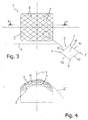
- the elementary sectors 5 are of polygonal shape with the number of sides equal to four. As illustrated in Figures 3 and 4, the elementary sectors 5 are orientated in such a way that their sides 10 are not parallel to the motion plane 4 on which the vehicle moves, but instead have a predetermined inclination with respect to it: at least one pair of sides 10 of each elementary sector 5 (in the specific example all the sides 10) are therefore inclined with respect to the motion plane 4 on which the vehicle moves (the horizontal plane).
- the elementary sectors 5 have a rhomboidal shape and have respective lower vertices 7 facing the plane 4.
- the elementary reflecting surfaces 6 are in turn curved surfaces, and have a concavity opposite to the concavity of the complex reflecting surface 2: the elementary reflecting surfaces 6, are joined along the sides of the respective elementary sectors 5.
- Figures 5 to 8 are two photometric diagrams (in iso Candles) which plot the values of luminous intensity detected in experimental tests conducted (in a manner prescribed by ECE regulations) on the reflector 1 of the invention having elementary sectors 5 of the previously-described form and illustrated in Figures 3 and 4, respectively measured on a square frame of angular dimensions 30° by 30° and on a rectangular window of angular dimensions 20° by 10°
- Figures 7 and 8 are the corresponding measurements of luminous intensity for the reflector 1a having generally similar conformation and equivalent dimensions to the reflector 1 of the invention, but formed of elementary reflecting surfaces of known type in the specific example of square form with pairs of sides parallel to the motion plane on which the vehicle moves (as illustrated in Figures 1 and 2).
- the reflector according to the invention has, with respect to the known reflector and in otherwise equivalent conditions, a superior output both on a 30° x 30° window and on a 20° x 10° window (which among other things, is the field of measurement envisaged by the international regulations): in particular, the output of a side light equipped with the reflector of the invention, with respect to a side light provided with a conventional reflector, is greater by more than 6% as measured on a 30° x 30° window and by more than 40% if measured on a 20° x 10° window, thanks to the innovative geometry of the complex surface and in particular to the form and disposition of the elementary reflecting surfaces of which it is composed.
- elementary reflecting surfaces 6 of different shape from that indicated can be utilised: in particular, elementary reflecting surfaces 6 of polygonal shape, still with four sides, can be utilised, for example square or rectangular surfaces, as long as the sides 10 of the elementary sectors 5 are inclined and not parallel with respect to the plane of advance of the vehicle: each elementary sector 5 has, therefore, in any event, its sides 10 inclined with respect to the plane parallel to the motion plane 4 on which the vehicle moves and passing through that elementary sector (for example through a lower corner 7 facing towards the plane 4): the improvement effect on the performance of the reflector 1, in fact, is due mainly to the fact that at least some of the edges along which the elementary reflecting surfaces 6 are connected, which together form the complex reflecting surface 2, are inclined, that is with respect to the motion plane 4.
- the superior luminous yield of the reflector 1 is obtained if at least some of the sides 10 of the elementary sectors 5 are inclined with respect to the motion plane 4 of the vehicle, that is with respect to the optical axis 3 of the reflector 1 itself.
Landscapes
- Engineering & Computer Science (AREA)
- General Engineering & Computer Science (AREA)
- Non-Portable Lighting Devices Or Systems Thereof (AREA)
- Optical Elements Other Than Lenses (AREA)
Description
- The present invention relates to a reflector having a complex surface for an illumination device of a vehicle; the reflector of the invention has reflecting surfaces of a new concept which make is possible to obtain, with respect to known configurations, improved photometric performance together with new aesthetic aspects, achieving this within extremely restricted dimensions.
- As is known, illumination devices of vehicles (in particular headlamps and side lights) generally comprise a light source the beam of which is suitably directed and modified by a reflector which gives the beam the desired optical characteristics for each specific function. In particular, the use of the so-called "complex" surfaces has been widely used to date, being formed by different portions each having their own shape or geometry.
- One known example of this type of reflector for illumination devices for motor vehicles is illustrated in the attached Figures 1 and 2, which are, respectively, a front view and a sectional view (taken on the line II-II of Figure 1) of a
reflector 1a of the type having a known complex surface configuration. Thereflector 1a has a complex reflectingsurface 2 with a predeterminedoptical axis 3 and is intended, in use, to be mounted on an associated illumination device of the vehicle in such a way that theoptical axis 3 is substantially parallel to the motion plane on which the vehicle moves, schematically represented by thebroken line 4 in Figure 1 (which represents the motion plane). Thecomplex reflecting surface 2 is constituted by a plurality ofsectors 5 of square shape (or rectangular in a variant which is also known) lying adjacent one another and mutually joined along respective adjacent sides: thereflector 1a is mounted on the vehicle in such a way that each of the square or rectangular elementary reflecting surfaces has a first pair of opposite sides parallel to the motion plane on which the vehicle moves, that is to the ground, and a second pair of opposite sides orthogonal thereto. - A vehicle illumination device according to the preamble of
claim 1 is known from US 1670837 A, and comprises a head lamp reflector with flat elementary sectors of polygonal shape. - Reflectors having complex surfaces of the type briefly outlined here have the disadvantage of providing relatively poor photometric performance: in particular, the luminous intensity is relatively low with respect to the luminous power emitted by the source.
- On the other hand it is known that the adoption of complex surfaces serves also to obtain aesthetic solutions which cannot be achieved with traditional optics. The use of elementary reflecting surfaces of square or rectangular form strongly limits the possibility of obtaining aesthetic aspects of a particular effect.
- It is an object of the present invention to provide a reflector, which while being simple and economic to produce, has, for the same dimensions as known reflectors, particularly high characteristics of efficiency and luminous intensity, at the same time allowing aesthetic aspects of a particular effect to be achieved.
- This object is achieved by the invention, which relates to a device according to
claim 1. It comprises a reflector having a complex surface for an illumination device of a vehicle, the reflector having a base surface with predetermined optical axis and a complex reflecting surface with an optical axis substantially coinciding with the said optical axis of the base surface, the said complex reflecting surface comprising a plurality of elementary sectors of predetermined shape supporting on the said base surface and provided with respective elementary reflecting surfaces, the said elementary sectors being of polygonal form and being positioned adjacent one another and mutually connected along respective adjacent sides to constitute the said complex reflecting surface, the reflector being mountable upon the said illumination device with the said optical axis substantially parallel to or convergent with a surface on which the vehicle moves. The said elementary sectors are of polygonal form with a number of sides equal to four; said elementary sectors are orientated in such a way that the said sides are not parallel to the said motion plane but have a predetermined inclination with respect thereto, and they have curved convex surfaces. - In this way the reflector according to the invention, while being simple and economical to produce and of extremely limited dimensions, has characteristics of particularly high luminous intensity, greater than conventional reflectors of comparable dimensions, and moreover makes it possible to achieve new aesthetic aspect of particular effect.
- Further characteristics and advantages of the present invention will become more clearly apparent from the following description of a non-limitative embodiment thereof , with reference to the figures of the attached drawings in which;
- Figure 1 is a schematic front view of a complex surface reflector of known type;
- Figure 2 is a sectional view taken on the line II-II of Figure 1;
- Figure 3 is a schematic front view of a complex surface reflector according to the present invention, with a detail enlarged for clarity;
- Figure 4 is a sectional view taken on the line IV-IV of Figure 3; Figures 5 and 6 are two photometric diagrams (in iso candles) of the values of luminous intensity detected in experimental tests on the reflector of Figure 3 (according to the invention) detected respectively on a square window of angular width of 30° and on a rectangular window of
angular width 20° by 10°, in accordance with the international regulations on the subject; - Figures 7 and 8 are two diagrams corresponding to those of Figures 5 and 6 and illustrate the efficiency of luminous intensity of the (known) reflector of Figure 1 having dimensions comparable with the reflector of the invention.
- With reference to Figures 3 and 4 (in which the same reference numerals indicate the same or similar details as those already used in Figures 1 and 2) a
reflector 1 for an illumination device (known and not illustrated for simplicity) of a vehicle, in particular a motor vehicle, has a complex reflectingsurface 2 with a predetermined optical axis 3: thereflector 1 is intended, in use, to be mounted on an associated illumination device of the vehicle in such a way that theoptical axis 3 lies substantially parallel to or convergent to a motion plane on which the vehicle moves, schematically represented by thebroken line 4 in Figure 1 (representing the plane of advance). - The
reflector 1 can be shaped in any way and the complex reflectingsurface 2 can consequentially have a different shape: in any case, it is possible to identify a base surface 2' which represents the general form of the reflector 1' the base surface 2' can be a surface of revolution or translation which can be described with a relatively simple equation, but can also be one which cannot be described in simple mathematical terms. In the non-limitative specific example illustrated the base surface 2' has a curvature and predetermined concavity and moreover has an optical axis substantially coincident with theoptical axis 3 of thecomplex reflecting surface 2. - The
reflector 1 comprises a plurality ofelementary sectors 5 of predetermined shape, provided with respective elementary reflectingsurfaces 6 with predetermined curvature: in particular, theelementary sectors 5 are of polygonal shape with fourcorners 7 and foursides 10, lying adjacent one another and joined together along respectiveadjacent sides 10 and supported on the base surface 2', by theircorners 7 and/or by theirsides 10 in such a way as to constitute the complex reflectingsurface 2 which, in the specific example, is a surface having a predetermined concavity: theelementary sectors 5 lie alongside one another and are connected to one another with a predetermined inclination to constitute the complex reflectingsurface 2 in such a way that respective adjacent sides of each pair of contiguouselementary sectors 5 are joined together and have a predetermined inclination with respect to the other to constitute an edge. - According to the invention the
elementary sectors 5 are of polygonal shape with the number of sides equal to four. As illustrated in Figures 3 and 4, theelementary sectors 5 are orientated in such a way that theirsides 10 are not parallel to themotion plane 4 on which the vehicle moves, but instead have a predetermined inclination with respect to it: at least one pair ofsides 10 of each elementary sector 5 (in the specific example all the sides 10) are therefore inclined with respect to themotion plane 4 on which the vehicle moves (the horizontal plane). - In the non-limitative example illustrated in Figures 3 and 4, the
elementary sectors 5 have a rhomboidal shape and have respectivelower vertices 7 facing theplane 4. - According to the invention, the elementary reflecting
surfaces 6 are in turn curved surfaces, and have a concavity opposite to the concavity of the complex reflecting surface 2: the elementary reflectingsurfaces 6, are joined along the sides of the respectiveelementary sectors 5. - The superior photometric performance of the reflector according to the invention with respect to a conventional reflector of equivalent dimensions and overall shape, but utilising known reflecting surfaces, is illustrated in Figures 5 to 8: in particular Figures 5 and 6 are two photometric diagrams (in iso Candles) which plot the values of luminous intensity detected in experimental tests conducted (in a manner prescribed by ECE regulations) on the
reflector 1 of the invention havingelementary sectors 5 of the previously-described form and illustrated in Figures 3 and 4, respectively measured on a square frame of angular dimensions 30° by 30° and on a rectangular window ofangular dimensions 20° by 10°, Figures 7 and 8 are the corresponding measurements of luminous intensity for thereflector 1a having generally similar conformation and equivalent dimensions to thereflector 1 of the invention, but formed of elementary reflecting surfaces of known type in the specific example of square form with pairs of sides parallel to the motion plane on which the vehicle moves (as illustrated in Figures 1 and 2). - The results of the experimental tests show that the reflector according to the invention has, with respect to the known reflector and in otherwise equivalent conditions, a superior output both on a 30° x 30° window and on a 20° x 10° window (which among other things, is the field of measurement envisaged by the international regulations): in particular, the output of a side light equipped with the reflector of the invention, with respect to a side light provided with a conventional reflector, is greater by more than 6% as measured on a 30° x 30° window and by more than 40% if measured on a 20° x 10° window, thanks to the innovative geometry of the complex surface and in particular to the form and disposition of the elementary reflecting surfaces of which it is composed.
- It is, therefore, clear that the reflector described and illustrated here can have numerous modifications and variations introduced thereto without by this departing from the scope of the present invention as defined by the claims.
- For example, elementary reflecting
surfaces 6 of different shape from that indicated can be utilised: in particular, elementary reflectingsurfaces 6 of polygonal shape, still with four sides, can be utilised, for example square or rectangular surfaces, as long as thesides 10 of theelementary sectors 5 are inclined and not parallel with respect to the plane of advance of the vehicle: eachelementary sector 5 has, therefore, in any event, itssides 10 inclined with respect to the plane parallel to themotion plane 4 on which the vehicle moves and passing through that elementary sector (for example through alower corner 7 facing towards the plane 4): the improvement effect on the performance of thereflector 1, in fact, is due mainly to the fact that at least some of the edges along which the elementary reflectingsurfaces 6 are connected, which together form thecomplex reflecting surface 2, are inclined, that is with respect to themotion plane 4. In other words, according to the invention, the superior luminous yield of thereflector 1 is obtained if at least some of thesides 10 of theelementary sectors 5 are inclined with respect to themotion plane 4 of the vehicle, that is with respect to theoptical axis 3 of thereflector 1 itself.
Claims (3)
- A vehicle illumination device with a complex surface reflector (1), the reflector having a base surface (2'), which is a curved surface having a predetermined concavity and a predetermined optical axis (3), and a complex reflecting surface (2), which has an optical axis substantially coinciding with the optical axis (3) of the base surface (2'), said complex reflecting surface (2) comprising a plurality of elementary sectors (5) of predetermined shape supported by the base surface (2') and provided with respective elementary reflective surfaces (6), the elementary sectors (5) being of polygonal shape, lying adjacent one another and being joined together along respective adjacent sides (10) to constitute said complex reflecting surface (2); the reflector (1) being mounted on the illumination device with said optical axis (3) substantially parallel to or convergent with a plane (4), and the device being mountable on a vehicle in such a way that said plane (4) is defined, in use, by a motion plane on which the vehicle provided with the device moves;
the elementary sectors (5) being of polygonal shape having four sides (10) and being orientated in such a way that none of the sides (10) is parallel to said plane (4), all said sides (10) having a predetermined inclination with respect to said plane (4); the device being characterised in that: the elementary reflecting surfaces (6) are curved convex surfaces, and said base reflecting surface (2') is a concave surface. - A reflector according to Claim 1, characterised in that said elementary sectors (5) are positioned adjacent to one another and joined together along said sides (10), the elementary sectors (5) being supported, at least by their corners (7), on said base surface (2').
- A reflector according to Claim 2, characterised in that said elementary sectors (5) have a rhomboidal form and are oriented in such a way as to present respective corners (7) towards said plane (4), none of said sides (10) being parallel to said plane (4).
Priority Applications (2)
| Application Number | Priority Date | Filing Date | Title |
|---|---|---|---|
| EP99830615A EP1089036B1 (en) | 1999-09-30 | 1999-09-30 | A reflector having a complex surface for an illumination device of a vehicle |
| DE69935328T DE69935328T2 (en) | 1999-09-30 | 1999-09-30 | Headlamp with a complex surface for the illumination device of a motor vehicle |
Applications Claiming Priority (1)
| Application Number | Priority Date | Filing Date | Title |
|---|---|---|---|
| EP99830615A EP1089036B1 (en) | 1999-09-30 | 1999-09-30 | A reflector having a complex surface for an illumination device of a vehicle |
Publications (3)
| Publication Number | Publication Date |
|---|---|
| EP1089036A1 EP1089036A1 (en) | 2001-04-04 |
| EP1089036A9 EP1089036A9 (en) | 2001-08-29 |
| EP1089036B1 true EP1089036B1 (en) | 2007-02-28 |
Family
ID=8243603
Family Applications (1)
| Application Number | Title | Priority Date | Filing Date |
|---|---|---|---|
| EP99830615A Revoked EP1089036B1 (en) | 1999-09-30 | 1999-09-30 | A reflector having a complex surface for an illumination device of a vehicle |
Country Status (2)
| Country | Link |
|---|---|
| EP (1) | EP1089036B1 (en) |
| DE (1) | DE69935328T2 (en) |
Family Cites Families (3)
| Publication number | Priority date | Publication date | Assignee | Title |
|---|---|---|---|---|
| US1670837A (en) * | 1924-01-31 | 1928-05-22 | Gen Motors Corp | Head-lamp reflector |
| US3511983A (en) * | 1967-04-10 | 1970-05-12 | Corning Glass Works | Lighting device for dental and surgical procedures |
| IT1267221B1 (en) * | 1994-04-20 | 1997-01-28 | Seima Italiana Spa | HEADLIGHT FOR MOTOR VEHICLES WITH LENS REFLECTOR |
-
1999
- 1999-09-30 EP EP99830615A patent/EP1089036B1/en not_active Revoked
- 1999-09-30 DE DE69935328T patent/DE69935328T2/en not_active Revoked
Also Published As
| Publication number | Publication date |
|---|---|
| DE69935328T2 (en) | 2007-11-22 |
| DE69935328D1 (en) | 2007-04-12 |
| EP1089036A9 (en) | 2001-08-29 |
| EP1089036A1 (en) | 2001-04-04 |
Similar Documents
| Publication | Publication Date | Title |
|---|---|---|
| US6805476B2 (en) | Led-type vehicular lamp having uniform brightness | |
| EP3212994B1 (en) | A lamp assembly for a vehicle | |
| US20050162857A1 (en) | Lamp unit for vehicle and illumination lamp for vehicle | |
| JPS61245401A (en) | Main beam head lamp for autmobile combining ellipsoidal reflector and paraboloidal reflector | |
| JP2003281909A (en) | LED lamp reflector, LED lamp lens and spot projector | |
| JP4007153B2 (en) | Vehicle lighting | |
| JP4023769B2 (en) | LIGHT EMITTING UNIT AND VEHICLE LIGHT EQUIPPED WITH THE LIGHT EMITTING UNIT | |
| ES2334132T3 (en) | MOTOR VEHICLE PROJECTOR DEVICE EQUIPPED WITH ELECTROLUMINISCENT DIODES. | |
| EP2419672A1 (en) | Multi-functional motor vehicle light | |
| EP1092917B1 (en) | Lighting device for motor vehicles having a highly discontinuous reflective surface | |
| JP3988393B2 (en) | Infrared projector | |
| US5045982A (en) | Wide angle warning light | |
| JP3919655B2 (en) | Vehicle lighting | |
| US4545001A (en) | Sealed lens member for use in a motor vehicle lighting system | |
| EP1089036A1 (en) | A reflector having a complex surface for an illumination device of a vehicle | |
| JP4404492B2 (en) | Infrared projector | |
| KR100294931B1 (en) | Headlight for vehicles | |
| JP2002270008A (en) | Infrared light projector for vehicles | |
| ES2253791T3 (en) | HEADLIGHT FOR MOTOR VEHICLES WITH DOUBLE FILAMENT LAMP. | |
| JP4138195B2 (en) | Vehicle lighting | |
| KR100739213B1 (en) | Reflector structure of street light | |
| JP2002245811A (en) | Vehicle headlights | |
| EP2484960B1 (en) | Optical unit and vehicular lamp | |
| KR20110002797U (en) | The reflector structure of Streetlight | |
| RU39678U1 (en) | LIGHT REPEATER OF THE SIGNAL OF THE TURN OF THE MOTOR VEHICLE |
Legal Events
| Date | Code | Title | Description |
|---|---|---|---|
| PUAI | Public reference made under article 153(3) epc to a published international application that has entered the european phase |
Free format text: ORIGINAL CODE: 0009012 |
|
| AK | Designated contracting states |
Kind code of ref document: A1 Designated state(s): DE ES FR GB IT |
|
| AX | Request for extension of the european patent |
Free format text: AL;LT;LV;MK;RO;SI |
|
| 17P | Request for examination filed |
Effective date: 20011003 |
|
| AKX | Designation fees paid |
Free format text: DE ES FR GB IT |
|
| GRAP | Despatch of communication of intention to grant a patent |
Free format text: ORIGINAL CODE: EPIDOSNIGR1 |
|
| RIC1 | Information provided on ipc code assigned before grant |
Ipc: F21V 7/09 20060101AFI20060627BHEP |
|
| GRAS | Grant fee paid |
Free format text: ORIGINAL CODE: EPIDOSNIGR3 |
|
| GRAA | (expected) grant |
Free format text: ORIGINAL CODE: 0009210 |
|
| AK | Designated contracting states |
Kind code of ref document: B1 Designated state(s): DE ES FR GB IT |
|
| REG | Reference to a national code |
Ref country code: GB Ref legal event code: FG4D |
|
| REF | Corresponds to: |
Ref document number: 69935328 Country of ref document: DE Date of ref document: 20070412 Kind code of ref document: P |
|
| PG25 | Lapsed in a contracting state [announced via postgrant information from national office to epo] |
Ref country code: ES Free format text: LAPSE BECAUSE OF FAILURE TO SUBMIT A TRANSLATION OF THE DESCRIPTION OR TO PAY THE FEE WITHIN THE PRESCRIBED TIME-LIMIT Effective date: 20070608 |
|
| ET | Fr: translation filed | ||
| PLBI | Opposition filed |
Free format text: ORIGINAL CODE: 0009260 |
|
| PLAX | Notice of opposition and request to file observation + time limit sent |
Free format text: ORIGINAL CODE: EPIDOSNOBS2 |
|
| 26 | Opposition filed |
Opponent name: VALEO VISION Effective date: 20071128 |
|
| PLAF | Information modified related to communication of a notice of opposition and request to file observations + time limit |
Free format text: ORIGINAL CODE: EPIDOSCOBS2 |
|
| PG25 | Lapsed in a contracting state [announced via postgrant information from national office to epo] |
Ref country code: IT Free format text: LAPSE BECAUSE OF NON-PAYMENT OF DUE FEES Effective date: 20070930 |
|
| GBPC | Gb: european patent ceased through non-payment of renewal fee |
Effective date: 20070930 |
|
| PLBB | Reply of patent proprietor to notice(s) of opposition received |
Free format text: ORIGINAL CODE: EPIDOSNOBS3 |
|
| PG25 | Lapsed in a contracting state [announced via postgrant information from national office to epo] |
Ref country code: GB Free format text: LAPSE BECAUSE OF NON-PAYMENT OF DUE FEES Effective date: 20070930 |
|
| RDAF | Communication despatched that patent is revoked |
Free format text: ORIGINAL CODE: EPIDOSNREV1 |
|
| PGFP | Annual fee paid to national office [announced via postgrant information from national office to epo] |
Ref country code: DE Payment date: 20091008 Year of fee payment: 11 |
|
| RDAG | Patent revoked |
Free format text: ORIGINAL CODE: 0009271 |
|
| STAA | Information on the status of an ep patent application or granted ep patent |
Free format text: STATUS: PATENT REVOKED |
|
| 27W | Patent revoked |
Effective date: 20090922 |
|
| PGFP | Annual fee paid to national office [announced via postgrant information from national office to epo] |
Ref country code: FR Payment date: 20091021 Year of fee payment: 11 |