EP1088909B1 - Thermal barrier coating system of a turbine component - Google Patents
Thermal barrier coating system of a turbine component Download PDFInfo
- Publication number
- EP1088909B1 EP1088909B1 EP00308537A EP00308537A EP1088909B1 EP 1088909 B1 EP1088909 B1 EP 1088909B1 EP 00308537 A EP00308537 A EP 00308537A EP 00308537 A EP00308537 A EP 00308537A EP 1088909 B1 EP1088909 B1 EP 1088909B1
- Authority
- EP
- European Patent Office
- Prior art keywords
- oxidation
- alloy
- region
- bondcoat
- resistant
- Prior art date
- Legal status (The legal status is an assumption and is not a legal conclusion. Google has not performed a legal analysis and makes no representation as to the accuracy of the status listed.)
- Expired - Lifetime
Links
Images

Classifications
-
- C—CHEMISTRY; METALLURGY
- C23—COATING METALLIC MATERIAL; COATING MATERIAL WITH METALLIC MATERIAL; CHEMICAL SURFACE TREATMENT; DIFFUSION TREATMENT OF METALLIC MATERIAL; COATING BY VACUUM EVAPORATION, BY SPUTTERING, BY ION IMPLANTATION OR BY CHEMICAL VAPOUR DEPOSITION, IN GENERAL; INHIBITING CORROSION OF METALLIC MATERIAL OR INCRUSTATION IN GENERAL
- C23C—COATING METALLIC MATERIAL; COATING MATERIAL WITH METALLIC MATERIAL; SURFACE TREATMENT OF METALLIC MATERIAL BY DIFFUSION INTO THE SURFACE, BY CHEMICAL CONVERSION OR SUBSTITUTION; COATING BY VACUUM EVAPORATION, BY SPUTTERING, BY ION IMPLANTATION OR BY CHEMICAL VAPOUR DEPOSITION, IN GENERAL
- C23C4/00—Coating by spraying the coating material in the molten state, e.g. by flame, plasma or electric discharge
- C23C4/12—Coating by spraying the coating material in the molten state, e.g. by flame, plasma or electric discharge characterised by the method of spraying
-
- C—CHEMISTRY; METALLURGY
- C23—COATING METALLIC MATERIAL; COATING MATERIAL WITH METALLIC MATERIAL; CHEMICAL SURFACE TREATMENT; DIFFUSION TREATMENT OF METALLIC MATERIAL; COATING BY VACUUM EVAPORATION, BY SPUTTERING, BY ION IMPLANTATION OR BY CHEMICAL VAPOUR DEPOSITION, IN GENERAL; INHIBITING CORROSION OF METALLIC MATERIAL OR INCRUSTATION IN GENERAL
- C23C—COATING METALLIC MATERIAL; COATING MATERIAL WITH METALLIC MATERIAL; SURFACE TREATMENT OF METALLIC MATERIAL BY DIFFUSION INTO THE SURFACE, BY CHEMICAL CONVERSION OR SUBSTITUTION; COATING BY VACUUM EVAPORATION, BY SPUTTERING, BY ION IMPLANTATION OR BY CHEMICAL VAPOUR DEPOSITION, IN GENERAL
- C23C28/00—Coating for obtaining at least two superposed coatings either by methods not provided for in a single one of groups C23C2/00 - C23C26/00 or by combinations of methods provided for in subclasses C23C and C25C or C25D
- C23C28/30—Coatings combining at least one metallic layer and at least one inorganic non-metallic layer
- C23C28/32—Coatings combining at least one metallic layer and at least one inorganic non-metallic layer including at least one pure metallic layer
- C23C28/321—Coatings combining at least one metallic layer and at least one inorganic non-metallic layer including at least one pure metallic layer with at least one metal alloy layer
- C23C28/3215—Coatings combining at least one metallic layer and at least one inorganic non-metallic layer including at least one pure metallic layer with at least one metal alloy layer at least one MCrAlX layer
-
- C—CHEMISTRY; METALLURGY
- C23—COATING METALLIC MATERIAL; COATING MATERIAL WITH METALLIC MATERIAL; CHEMICAL SURFACE TREATMENT; DIFFUSION TREATMENT OF METALLIC MATERIAL; COATING BY VACUUM EVAPORATION, BY SPUTTERING, BY ION IMPLANTATION OR BY CHEMICAL VAPOUR DEPOSITION, IN GENERAL; INHIBITING CORROSION OF METALLIC MATERIAL OR INCRUSTATION IN GENERAL
- C23C—COATING METALLIC MATERIAL; COATING MATERIAL WITH METALLIC MATERIAL; SURFACE TREATMENT OF METALLIC MATERIAL BY DIFFUSION INTO THE SURFACE, BY CHEMICAL CONVERSION OR SUBSTITUTION; COATING BY VACUUM EVAPORATION, BY SPUTTERING, BY ION IMPLANTATION OR BY CHEMICAL VAPOUR DEPOSITION, IN GENERAL
- C23C28/00—Coating for obtaining at least two superposed coatings either by methods not provided for in a single one of groups C23C2/00 - C23C26/00 or by combinations of methods provided for in subclasses C23C and C25C or C25D
- C23C28/30—Coatings combining at least one metallic layer and at least one inorganic non-metallic layer
- C23C28/32—Coatings combining at least one metallic layer and at least one inorganic non-metallic layer including at least one pure metallic layer
- C23C28/325—Coatings combining at least one metallic layer and at least one inorganic non-metallic layer including at least one pure metallic layer with layers graded in composition or in physical properties
-
- C—CHEMISTRY; METALLURGY
- C23—COATING METALLIC MATERIAL; COATING MATERIAL WITH METALLIC MATERIAL; CHEMICAL SURFACE TREATMENT; DIFFUSION TREATMENT OF METALLIC MATERIAL; COATING BY VACUUM EVAPORATION, BY SPUTTERING, BY ION IMPLANTATION OR BY CHEMICAL VAPOUR DEPOSITION, IN GENERAL; INHIBITING CORROSION OF METALLIC MATERIAL OR INCRUSTATION IN GENERAL
- C23C—COATING METALLIC MATERIAL; COATING MATERIAL WITH METALLIC MATERIAL; SURFACE TREATMENT OF METALLIC MATERIAL BY DIFFUSION INTO THE SURFACE, BY CHEMICAL CONVERSION OR SUBSTITUTION; COATING BY VACUUM EVAPORATION, BY SPUTTERING, BY ION IMPLANTATION OR BY CHEMICAL VAPOUR DEPOSITION, IN GENERAL
- C23C28/00—Coating for obtaining at least two superposed coatings either by methods not provided for in a single one of groups C23C2/00 - C23C26/00 or by combinations of methods provided for in subclasses C23C and C25C or C25D
- C23C28/30—Coatings combining at least one metallic layer and at least one inorganic non-metallic layer
- C23C28/34—Coatings combining at least one metallic layer and at least one inorganic non-metallic layer including at least one inorganic non-metallic material layer, e.g. metal carbide, nitride, boride, silicide layer and their mixtures, enamels, phosphates and sulphates
- C23C28/345—Coatings combining at least one metallic layer and at least one inorganic non-metallic layer including at least one inorganic non-metallic material layer, e.g. metal carbide, nitride, boride, silicide layer and their mixtures, enamels, phosphates and sulphates with at least one oxide layer
- C23C28/3455—Coatings combining at least one metallic layer and at least one inorganic non-metallic layer including at least one inorganic non-metallic material layer, e.g. metal carbide, nitride, boride, silicide layer and their mixtures, enamels, phosphates and sulphates with at least one oxide layer with a refractory ceramic layer, e.g. refractory metal oxide, ZrO2, rare earth oxides or a thermal barrier system comprising at least one refractory oxide layer
-
- C—CHEMISTRY; METALLURGY
- C23—COATING METALLIC MATERIAL; COATING MATERIAL WITH METALLIC MATERIAL; CHEMICAL SURFACE TREATMENT; DIFFUSION TREATMENT OF METALLIC MATERIAL; COATING BY VACUUM EVAPORATION, BY SPUTTERING, BY ION IMPLANTATION OR BY CHEMICAL VAPOUR DEPOSITION, IN GENERAL; INHIBITING CORROSION OF METALLIC MATERIAL OR INCRUSTATION IN GENERAL
- C23C—COATING METALLIC MATERIAL; COATING MATERIAL WITH METALLIC MATERIAL; SURFACE TREATMENT OF METALLIC MATERIAL BY DIFFUSION INTO THE SURFACE, BY CHEMICAL CONVERSION OR SUBSTITUTION; COATING BY VACUUM EVAPORATION, BY SPUTTERING, BY ION IMPLANTATION OR BY CHEMICAL VAPOUR DEPOSITION, IN GENERAL
- C23C4/00—Coating by spraying the coating material in the molten state, e.g. by flame, plasma or electric discharge
- C23C4/02—Pretreatment of the material to be coated, e.g. for coating on selected surface areas
-
- C—CHEMISTRY; METALLURGY
- C23—COATING METALLIC MATERIAL; COATING MATERIAL WITH METALLIC MATERIAL; CHEMICAL SURFACE TREATMENT; DIFFUSION TREATMENT OF METALLIC MATERIAL; COATING BY VACUUM EVAPORATION, BY SPUTTERING, BY ION IMPLANTATION OR BY CHEMICAL VAPOUR DEPOSITION, IN GENERAL; INHIBITING CORROSION OF METALLIC MATERIAL OR INCRUSTATION IN GENERAL
- C23C—COATING METALLIC MATERIAL; COATING MATERIAL WITH METALLIC MATERIAL; SURFACE TREATMENT OF METALLIC MATERIAL BY DIFFUSION INTO THE SURFACE, BY CHEMICAL CONVERSION OR SUBSTITUTION; COATING BY VACUUM EVAPORATION, BY SPUTTERING, BY ION IMPLANTATION OR BY CHEMICAL VAPOUR DEPOSITION, IN GENERAL
- C23C4/00—Coating by spraying the coating material in the molten state, e.g. by flame, plasma or electric discharge
- C23C4/04—Coating by spraying the coating material in the molten state, e.g. by flame, plasma or electric discharge characterised by the coating material
- C23C4/06—Metallic material
- C23C4/073—Metallic material containing MCrAl or MCrAlY alloys, where M is nickel, cobalt or iron, with or without non-metal elements
-
- Y—GENERAL TAGGING OF NEW TECHNOLOGICAL DEVELOPMENTS; GENERAL TAGGING OF CROSS-SECTIONAL TECHNOLOGIES SPANNING OVER SEVERAL SECTIONS OF THE IPC; TECHNICAL SUBJECTS COVERED BY FORMER USPC CROSS-REFERENCE ART COLLECTIONS [XRACs] AND DIGESTS
- Y02—TECHNOLOGIES OR APPLICATIONS FOR MITIGATION OR ADAPTATION AGAINST CLIMATE CHANGE
- Y02T—CLIMATE CHANGE MITIGATION TECHNOLOGIES RELATED TO TRANSPORTATION
- Y02T50/00—Aeronautics or air transport
- Y02T50/60—Efficient propulsion technologies, e.g. for aircraft
-
- Y—GENERAL TAGGING OF NEW TECHNOLOGICAL DEVELOPMENTS; GENERAL TAGGING OF CROSS-SECTIONAL TECHNOLOGIES SPANNING OVER SEVERAL SECTIONS OF THE IPC; TECHNICAL SUBJECTS COVERED BY FORMER USPC CROSS-REFERENCE ART COLLECTIONS [XRACs] AND DIGESTS
- Y10—TECHNICAL SUBJECTS COVERED BY FORMER USPC
- Y10T—TECHNICAL SUBJECTS COVERED BY FORMER US CLASSIFICATION
- Y10T428/00—Stock material or miscellaneous articles
- Y10T428/12—All metal or with adjacent metals
- Y10T428/12493—Composite; i.e., plural, adjacent, spatially distinct metal components [e.g., layers, joint, etc.]
- Y10T428/12535—Composite; i.e., plural, adjacent, spatially distinct metal components [e.g., layers, joint, etc.] with additional, spatially distinct nonmetal component
- Y10T428/12611—Oxide-containing component
- Y10T428/12618—Plural oxides
-
- Y—GENERAL TAGGING OF NEW TECHNOLOGICAL DEVELOPMENTS; GENERAL TAGGING OF CROSS-SECTIONAL TECHNOLOGIES SPANNING OVER SEVERAL SECTIONS OF THE IPC; TECHNICAL SUBJECTS COVERED BY FORMER USPC CROSS-REFERENCE ART COLLECTIONS [XRACs] AND DIGESTS
- Y10—TECHNICAL SUBJECTS COVERED BY FORMER USPC
- Y10T—TECHNICAL SUBJECTS COVERED BY FORMER US CLASSIFICATION
- Y10T428/00—Stock material or miscellaneous articles
- Y10T428/12—All metal or with adjacent metals
- Y10T428/12493—Composite; i.e., plural, adjacent, spatially distinct metal components [e.g., layers, joint, etc.]
- Y10T428/12736—Al-base component
- Y10T428/1275—Next to Group VIII or IB metal-base component
- Y10T428/12757—Fe
-
- Y—GENERAL TAGGING OF NEW TECHNOLOGICAL DEVELOPMENTS; GENERAL TAGGING OF CROSS-SECTIONAL TECHNOLOGIES SPANNING OVER SEVERAL SECTIONS OF THE IPC; TECHNICAL SUBJECTS COVERED BY FORMER USPC CROSS-REFERENCE ART COLLECTIONS [XRACs] AND DIGESTS
- Y10—TECHNICAL SUBJECTS COVERED BY FORMER USPC
- Y10T—TECHNICAL SUBJECTS COVERED BY FORMER US CLASSIFICATION
- Y10T428/00—Stock material or miscellaneous articles
- Y10T428/12—All metal or with adjacent metals
- Y10T428/12493—Composite; i.e., plural, adjacent, spatially distinct metal components [e.g., layers, joint, etc.]
- Y10T428/12771—Transition metal-base component
- Y10T428/12861—Group VIII or IB metal-base component
- Y10T428/12931—Co-, Fe-, or Ni-base components, alternative to each other
-
- Y—GENERAL TAGGING OF NEW TECHNOLOGICAL DEVELOPMENTS; GENERAL TAGGING OF CROSS-SECTIONAL TECHNOLOGIES SPANNING OVER SEVERAL SECTIONS OF THE IPC; TECHNICAL SUBJECTS COVERED BY FORMER USPC CROSS-REFERENCE ART COLLECTIONS [XRACs] AND DIGESTS
- Y10—TECHNICAL SUBJECTS COVERED BY FORMER USPC
- Y10T—TECHNICAL SUBJECTS COVERED BY FORMER US CLASSIFICATION
- Y10T428/00—Stock material or miscellaneous articles
- Y10T428/12—All metal or with adjacent metals
- Y10T428/12493—Composite; i.e., plural, adjacent, spatially distinct metal components [e.g., layers, joint, etc.]
- Y10T428/12771—Transition metal-base component
- Y10T428/12861—Group VIII or IB metal-base component
- Y10T428/12944—Ni-base component
Definitions
- the invention relates generally to thermal barrier coating systems, in particular, thermal barrier coating systems exposed to high temperatures such as in a gas turbine engine.
- TBC thermal barrier coating
- ZrO 2 zirconia
- bond coats are utilized.
- One type of bond coat is formed of MCrAIY, wherein M is chosen from the group consisting of iron, cobalt, nickel and combinations thereof.
- Such bond coats may be deposited thermal spray techniques, including low pressure plasma spray (LPPS), High Velocity-Oxy Fuel (HVOF), and air plasma spray (APS).
- LPPS low pressure plasma spray
- HVOF High Velocity-Oxy Fuel
- APS bond coats have been used for their ease of deposition and bond quality and integrity between the substrate and the TBC.
- Such bondcoats should be easily deposited, have improved oxidation- and/or corrosion-resistance, and provide a good adhesive interface for the overlying thermal barrier coating.
- a method for forming a thermal barrier coating system on a turbine engine component includes forming a bondcoat on the turbine engine component by thermally co-spraying first and second distinct alloy powders on the turbine engine component, to form an oxidation-resistant region the first alloy powder comprising a first MCrAIY alloy wherein M is selected from the group consisting of nickel, cobalt and combinations thereof . Then, aa bonding region is provided by thermally spraying a third alloy powder on the oxidation-resistant region, the third alloy powder comprising a second MCrAIY alloy, wherein M is selected from nickel, cobalt and combinations thereof. The oxidation-resistant region is more resistant to oxidation than the bonding region. A thermal barrier coating is then deposited so as to overlie the bondcoat.
- a turbine engine component in another embodiment, includes a substrate, and a bondcoat overlying the substrate.
- the bondcoat has an oxidation-resistant region, and a bonding region overlying the oxidation-resistant region, wherein the oxidation-resistant region is more resistant to oxidation than the bonding region.
- a thermal barrier coating overlies the bondcoat.
- a substrate generally in the form of a turbine engine component is treated so as to improve its high temperature performance, such as at temperatures above 1000 °C.
- the substrate is typically formed of a superalloy material, known for high temperature performance in terms of tensile strength, creep resistance, oxidation resistance, and corrosion resistance, for example.
- the superalloy component is typically formed of a nickel-base or a cobalt-base alloy, wherein nickel or cobalt is the single greatest element in the superalloy by weight.
- Illustrative nickel-base superalloys include at least about 40 wt% Ni, and at least one component from the group consisting of cobalt, chromium, aluminum, tungsten, molybdenum, titanium, and iron.
- Examples of nickel-base superalloys are designated by the trade names Inconel®, Nimonic®, Rene® (e.g., Rene®80-, Rene®95, Rene®142, and Rene®N5 alloys), and Udimet®, and include directionally solidified and single crystal superalloys.
- Illustrative cobalt-base superalloys include at least about 30 wt% Co, and at least one component from the group consisting of nickel, chromium, aluminum, tungsten, molybdenum, titanium, and iron.
- Examples of cobalt-base superalloys are designated by the trade names Hayrres®, Nozzaloy®, Stellite® and Ultimet®.
- the actual configuration of a substrate may vary widely, such as in the form of a combustor liner, combustor dome, shroud, bucket or blade, nozzle or vane. Blades are a typical application of TBC systems according to embodiments of the present invention.
- a bond coat is deposited by thermal spraying on the substrate.
- thermal spraying includes flame spraying, HVOF (high-velocity oxy-fuel) spraying, plasma spraying, and wire arc spraying.
- Plasma spraying includes air plasma spraying (APS), and low pressure plasma spraying (LPPS), also known as vacuum plasma spraying (VPS).
- APS air plasma spraying
- LPPS low pressure plasma spraying
- VPS vacuum plasma spraying
- the bondcoat contains at least two regions, including an oxidation-resistant region and a bonding region that overlies the oxidation-resistant region.
- the oxidation-resistant region protects the underlying substrate from oxidation and/or corrosive attack during actual use. While the bonding region can offer a certain degree of oxidation resistance, it has less resistance to oxidation than the oxidation-resistant region.
- the bonding region provides a compliance match and high surface area bonding interface to provide strong adhesion of the overlying thermal barrier coating thereto.
- the oxidation resistant region is formed by thermally co-spraying two distinct alloys, in powder form.
- the first alloy for the oxidation-resistant region is nickel- or cobalt-based, such as those already used for conventional bondcoats known by the general composition MCrAIY, wherein M is an element selected from the group consisting of nickel, cobalt and combinations thereof.
- the second alloy is effective to modify the oxidation characteristics of the material deposited by thermal spraying, and oxidation of the underlying substrate.
- the second alloy is believed to modify the deposited material and/or substrate either chemically or physically.
- the alloy contains silicon, which believed to be effective to retard oxidation of not only the oxidation-resistant region itself, but also to retard oxidation of the underlying substrate.
- the second alloy generally also modifies the oxidation-resistant region physically by increasing the density thereof, such as by a subsequent heat treatment at an elevated temperature after thermal spraying. While the heat treatment is carried out after thermal spraying, it need not follow immediately. For example, heat treatment can by carried out as part of a heat treatment step for the thermal barrier coating or substrate, such as known heat treatment processes for vertically microcracked TBC's or superalloy components.
- the second alloy typically either melts thereby filling the voids within the thermally sprayed material, or functions to increase the intrinsic densification rate of the alloy of the first powder, such as by liquid or solid phase sintering.
- the heat treatment may be effected to produce an alloy in the oxidation-resistant region that has a generally uniform composition, which composition has desirable oxidation and/or corrosion resistance.
- the uniform composition can be achieved by annealing, either by solid- or liquid-state interdiffusion of the alloy components during heat treatment. While densification of the thermally sprayed material is desired, it is not essential that full densification be achieved. Rather, slight increases in densification in the deposited material may be effective to decrease the degree of connectivity of voids (open porosity) present in the material, and hence, susceptibility of the underlying substrate to oxidation or corrosion.
- Slight densification is generally envisioned as 'pinching-off' the voids thereby producing "closed porosity". Indeed, as discussed below in connection with a particular example, no substantial densification was visually observed by cross-sectional photomicrographs, but significant improvements in the degree of oxidation of the underlying substrate were nevertheless observed.
- the first alloy is formed of a homogeneous superalloy composition such as MCrAIY, wherein M is selected from a group consisting of iron, cobalt, nickel and combinations thereof.
- M is selected from a group consisting of iron, cobalt, nickel and combinations thereof.
- the alloy is nickel-based (i.e. M is nickel), and is identified by the vendor designation Ni211, from Praxair.
- Ni211 has a nominal composition 22.0 Cr, 10.0 Al, 1.0 Y, balance Ni (all in weight percent).
- the second alloy is a superalloy braze alloy.
- the braze alloy composition typically contains one or more components for lowering the melting point of the thereof.
- Melting point suppressants for nickel-base and cobalt-base braze alloys include silicon, boron, phosphorous, or combinations thereof.
- the melting point suppressant is one of silicon or boron, or a combination thereof.
- the braze alloy contains nickel, chrome and silicon, such as alloy composition no. 5 below.
- Exemplary nickel-base braze alloy compositions include the following (components are designated in weight %):
- nickel-base braze alloy compositions include:
- Cobalt-base braze alloy compositions include:
- the bonding region is formed by thermally spraying a third alloy, in powder form.
- the third alloy is an MCrAIY alloy, wherein M is selected from a group consisting of iron, cobalt, nickel and combinations thereof.
- the third alloy is advantageously the same alloy as that of the first alloy.
- the third alloy is nickel-based (i.e. M is nickel), and is identified by the vendor designation Ni211, from Praxair.
- Ni211 has a nominal composition 67.0 Ni, 22.0 Cr, 10.0 Al, and 1.0 Y, all in weight percent.
- the transition from depositing the oxidation-resistant region to the bonding region is typically stepwise, whereby the feed of a mixture of the first and second powders is halted, feed of the third powder is initiated, and thermal spaying is then continued.
- This technique results in a bilayer bondcoat, each region being in the form of a distinct layer, which can be distinguished from each other by location of chemical species, as well as concentration of oxide material after furnace cycle testing or after actual use.
- the transition in thermal spraying may be made gradually, forming a bondcoat that is graded.
- the first and second powders are deposited, and the ratio of the two is changed such that feed of the second powder is gradually eliminated, forming an overlying region that is principally formed of the first alloy (such as MCrAIY).
- the bondcoat typically has a thickness within a range of about 25 microns to about 750 microns, such as about 100 microns to about 400 microns.
- the oxidation-resistant region typically has two main phases, including a first phase corresponding to the first alloy and a second phase corresponding to the second alloy.
- the two phases generally correspond to the respective compositions of the two initial powders.
- the level and morphology of the porosity in the oxidation-resistant region is typically modified, although significant increases in density may not be essential to achieve the desired improvement in oxidation resistance or substrate protection. That is, reducing the degree of connectivity of the porosity may be effective to decrease the availability of the substrate to oxidation and/or corrosion.
- the oxidation-resistant region typically has one of several microstructures, including an interconnected matrix phase in which the first phase is dispersed, the first phase and an intergranular second phase, or a homogeneous composition brought about by interdiffusion of the first and second phases.
- a thermal barrier coating is deposited on the bond coat, generally directly contacting the bonding region of the bondcoat.
- the thermal barrier coating is formed of a ceramic material such as zirconia, stabilized with at least one oxide, including yttria (Y 2 O 3 ), ceria (CeO 2 ), magnesia (MgO), scandia (Sc 2 O 3 ), and calcia.
- the thermal barrier coating is formed of yttria stabilized zirconia.
- the thermal barrier coating is generally deposited by one of several techniques such as by a thermal spray technique, including high-velocity oxy-fuel (HVOF) and plasma spray techniques.
- HVOF high-velocity oxy-fuel
- Plasma spray techniques include air plasma spray (APS), vacuum plasma spray (VPS), and low-pressure plasma spray (LPPS).
- vapor deposition techniques such as electron beam physical vapor deposition (EBPVD) can be utilized.
- EBPVD electron beam physical vapor deposition
- the thermal barrier coating typically has a thickness on the order of about 50 microns to about 2500 microns, such as about 75 microns to about 1250 microns. Typically, the thickness of the bond coat was less than about 500 microns, such as 400 microns.
- the bondcoat formed according to the techniques described above has both superior oxidation-resistance and superior bonding adhesion to the overlying thermal barrier coating.
- an oxidation-resistant region is formed that a level of oxidation resistance normally associated with processes that form intrinsically more dense layers, such as vacuum plasma spray (VPS) and high-velocity oxy-fuel (HVOF) techniques.
- VPS vacuum plasma spray
- HVOF high-velocity oxy-fuel
- the bonding region is made porous, providing a superior bonding interface to the overlying thermal barrier coating.
- the porous nature of the bonding region permits some degree of internal oxidation thereby providing a level of compliance to accommodate thermal expansion and contraction of the overlying thermal barrier coating.
- a Rene® N5 substrate in the form of a 1 inch diameter test coupon was coated.
- a Metco 7MB plasma spray torch was placed about 5 inches from the test coupon, and a mixture Ni211 powder (-140+325 mesh) and braze alloy (-140+325 mesh) was fed to the torch.
- the mixture contained a 25/75 wt% mixture of Ni211 powder/braze alloy powder.
- the torch current was set at 500 A to form a 5 mil thick oxidation resistant region. Air plasma spraying was stopped, and Ni211 (-325 mesh) was then fed to the torch without any braze alloy. Again the torch current was set to 500 A, to form a 10 mil thick bonding region.
- the thermal barrier coating system was completed with an air plasma sprayed thermal barrier coating, having a thickness of 20 mils.
- the coupon was then subjected to a heat treatment step, in vacuum for 30 minutes at 1177°C (2150 °F).
- the photomicrograph shows a substrate 10, the bondcoat 12, and the thermal barrier coating 14.
- the oxidation-resistant region and the bonding region are largely indistinguishable from each other, but can be more clearly distinguished with a microprobe plot showing the distribution of chemical species.
- Due to the deposition technique by APS, 'splat' lines are present in the deposited layer.
- the powders are melted and accelerated through ambient air towards the substrate.
- the molten alloy droplets are flattened and solidify.
- the deposited material has a layered structure, composed of areas of solidified alloy with interfacial regions, splat lines, which may contain some oxide and porosity. While it is believed that the oxidation-resistant region is densified to some extent so as to alter the nature of the porosity, marked densification from the heat treatment step was not observed.
- the sample was then subjected to furnace cycle testing (FCT) in air. Particularly, the sample was placed in a bottom loading furnace , heated to 1093°C (2000 °F) in approximately 10 minutes, held for 45 minutes, and then forced-air cooled to approximately 93°C (200 °F). After 200 of these thermal cycles, the sample was inspected.
- the microstructure at this particular stage in the cycling is shown in Figure 2 . As shown, the distinction between the oxidation-resistant region 16 and the bonding region 18 is clearly shown. The splat lines in the bonding region have been accentuated due to oxidation from exposure to the cycling test. It is believed that such oxidation contributes to a compliance match with the overlying thermal barrier coating.
- the oxidation resistant region showed little or no appreciable further oxidation of the splat lines and the substrate was protected from unwanted oxidation.
- the bonding region has a higher volume percentage of entrained oxide than the oxidation resistant region.
- the sample was subjected to additional heat cycling tests, until failure occurred.
- the improved bond coat sample had markedly superior (3X) resistance to delamination at both the TBC/bondcoat interface and the bondcoat/substrate interface.
- braze/MCrAIY ratios particularly at ratios of 0/100, 25/75, 75/25 and 100/0, on both N5 and Ni 413 alloys.
- Post deposition heat treatments were executed a 1177°C (2150°F) and at 1079°C (1975°F). Furnace cycle testing revealed similar durability increases for the N5 and Ni 413 samples with the 75:25 braze:NiCrAIY bondcoat chemistry.
- an improved thermal barrier coating system is provided. Improved adhesion of the thermal barrier coating to the underlying substrate is maintained by incorporation of a compliant bonding region of a bondcoat.
- an oxidation-resistant region of the bondcoat is effective to protect the underlying substrate from oxidation and/or corrosive attack during operation, which otherwise result in delamination.
- both regions can be deposited using the same technique, such as air plasma spray.
Description
- The invention relates generally to thermal barrier coating systems, in particular, thermal barrier coating systems exposed to high temperatures such as in a gas turbine engine.
- Higher operating temperatures for gas turbine engines have been continuously sought in the art in order to improve the operating efficiency of the engine. However, as operating temperatures are raised, the high temperature capabilities of the components in the engine must also increase. To this end, various nickel-base and cobalt-base superalloys have been employed, which incorporate oxidation-resistant and corrosion-resistant overlay and diffusion-type coatings.
- Further improvements in the high temperature capabilities of components have been realized by coating engine components with a thermal barrier coating (TBC), in addition to the overlay and diffusion-type coatings mentioned above. TBCs are generally formed of ceramic materials, such as zirconia (ZrO2) stabilized by an oxide material. To promote adhesion between the thermal barrier coating and the underlying substrate, bond coats are utilized. One type of bond coat is formed of MCrAIY, wherein M is chosen from the group consisting of iron, cobalt, nickel and combinations thereof.
- Such bond coats may be deposited thermal spray techniques, including low pressure plasma spray (LPPS), High Velocity-Oxy Fuel (HVOF), and air plasma spray (APS). Of these bond coats, APS bond coats have been used for their ease of deposition and bond quality and integrity between the substrate and the TBC. However, a need exists in the art for further improved bondcoats of a thermal barrier coating system. Such bondcoats should be easily deposited, have improved oxidation- and/or corrosion-resistance, and provide a good adhesive interface for the overlying thermal barrier coating.
- In one embodiment of the present invention, a method for forming a thermal barrier coating system on a turbine engine component is provided. The method includes forming a bondcoat on the turbine engine component by thermally co-spraying first and second distinct alloy powders on the turbine engine component, to form an oxidation-resistant region the first alloy powder comprising a first MCrAIY alloy wherein M is selected from the group consisting of nickel, cobalt and combinations thereof. Then, aa bonding region is provided by thermally spraying a third alloy powder on the oxidation-resistant region, the third alloy powder comprising a second MCrAIY alloy, wherein M is selected from nickel, cobalt and combinations thereof. The oxidation-resistant region is more resistant to oxidation than the bonding region. A thermal barrier coating is then deposited so as to overlie the bondcoat.
- In another embodiment of the present invention, a turbine engine component is provided. The component includes a substrate, and a bondcoat overlying the substrate. The bondcoat has an oxidation-resistant region, and a bonding region overlying the oxidation-resistant region, wherein the oxidation-resistant region is more resistant to oxidation than the bonding region. A thermal barrier coating overlies the bondcoat.
-
-
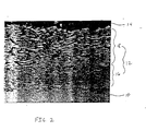
Figure 1 is a cross-sectional photomicrograph of an example of a thermal barrier coating system on a substrate, before heat cycling; and -
Figure 2 is a cross-sectional photomicrograph of the example illustrated inFigure 1 , after heat cycling. - According to an embodiment of the present invention, a substrate, generally in the form of a turbine engine component is treated so as to improve its high temperature performance, such as at temperatures above 1000 °C. The substrate is typically formed of a superalloy material, known for high temperature performance in terms of tensile strength, creep resistance, oxidation resistance, and corrosion resistance, for example. The superalloy component is typically formed of a nickel-base or a cobalt-base alloy, wherein nickel or cobalt is the single greatest element in the superalloy by weight. Illustrative nickel-base superalloys include at least about 40 wt% Ni, and at least one component from the group consisting of cobalt, chromium, aluminum, tungsten, molybdenum, titanium, and iron. Examples of nickel-base superalloys are designated by the trade names Inconel®, Nimonic®, Rene® (e.g., Rene®80-, Rene®95, Rene®142, and Rene®N5 alloys), and Udimet®, and include directionally solidified and single crystal superalloys. Illustrative cobalt-base superalloys include at least about 30 wt% Co, and at least one component from the group consisting of nickel, chromium, aluminum, tungsten, molybdenum, titanium, and iron. Examples of cobalt-base superalloys are designated by the trade names Hayrres®, Nozzaloy®, Stellite® and Ultimet®. The actual configuration of a substrate may vary widely, such as in the form of a combustor liner, combustor dome, shroud, bucket or blade, nozzle or vane. Blades are a typical application of TBC systems according to embodiments of the present invention.
- According to embodiments of the present invention, a bond coat is deposited by thermal spraying on the substrate. As used herein, thermal spraying includes flame spraying, HVOF (high-velocity oxy-fuel) spraying, plasma spraying, and wire arc spraying. Plasma spraying includes air plasma spraying (APS), and low pressure plasma spraying (LPPS), also known as vacuum plasma spraying (VPS). For ease of application and for reasons discussed hereinafter, air plasma spraying (APS) is generally used to deposit the bond coat according to embodiments of the present invention.
- The bondcoat contains at least two regions, including an oxidation-resistant region and a bonding region that overlies the oxidation-resistant region. The oxidation-resistant region protects the underlying substrate from oxidation and/or corrosive attack during actual use. While the bonding region can offer a certain degree of oxidation resistance, it has less resistance to oxidation than the oxidation-resistant region. The bonding region provides a compliance match and high surface area bonding interface to provide strong adhesion of the overlying thermal barrier coating thereto.
The oxidation resistant region is formed by thermally co-spraying two distinct alloys, in powder form. The first alloy for the oxidation-resistant region is nickel- or cobalt-based, such as those already used for conventional bondcoats known by the general composition MCrAIY, wherein M is an element selected from the group consisting of nickel, cobalt and combinations thereof. - According to a particular development of the present invention, the second alloy is effective to modify the oxidation characteristics of the material deposited by thermal spraying, and oxidation of the underlying substrate. The second alloy is believed to modify the deposited material and/or substrate either chemically or physically. In one embodiment, the alloy contains silicon, which believed to be effective to retard oxidation of not only the oxidation-resistant region itself, but also to retard oxidation of the underlying substrate.
- The second alloy generally also modifies the oxidation-resistant region physically by increasing the density thereof, such as by a subsequent heat treatment at an elevated temperature after thermal spraying. While the heat treatment is carried out after thermal spraying, it need not follow immediately. For example, heat treatment can by carried out as part of a heat treatment step for the thermal barrier coating or substrate, such as known heat treatment processes for vertically microcracked TBC's or superalloy components. The second alloy typically either melts thereby filling the voids within the thermally sprayed material, or functions to increase the intrinsic densification rate of the alloy of the first powder, such as by liquid or solid phase sintering. In yet another form, the heat treatment may be effected to produce an alloy in the oxidation-resistant region that has a generally uniform composition, which composition has desirable oxidation and/or corrosion resistance. In this embodiment, the uniform composition can be achieved by annealing, either by solid- or liquid-state interdiffusion of the alloy components during heat treatment.
While densification of the thermally sprayed material is desired, it is not essential that full densification be achieved. Rather, slight increases in densification in the deposited material may be effective to decrease the degree of connectivity of voids (open porosity) present in the material, and hence, susceptibility of the underlying substrate to oxidation or corrosion. Slight densification is generally envisioned as 'pinching-off' the voids thereby producing "closed porosity". Indeed, as discussed below in connection with a particular example, no substantial densification was visually observed by cross-sectional photomicrographs, but significant improvements in the degree of oxidation of the underlying substrate were nevertheless observed. - Typically, the first alloy is formed of a homogeneous superalloy composition such as MCrAIY, wherein M is selected from a group consisting of iron, cobalt, nickel and combinations thereof. In one particular embodiment, the alloy is nickel-based (i.e. M is nickel), and is identified by the vendor designation Ni211, from Praxair. Ni211 has a nominal composition 22.0 Cr, 10.0 Al, 1.0 Y, balance Ni (all in weight percent).
- The second alloy is a superalloy braze alloy. The braze alloy composition typically contains one or more components for lowering the melting point of the thereof. Melting point suppressants for nickel-base and cobalt-base braze alloys include silicon, boron, phosphorous, or combinations thereof. Preferably, the melting point suppressant is one of silicon or boron, or a combination thereof. In one particular embodiment, the braze alloy contains nickel, chrome and silicon, such as alloy composition no. 5 below. Exemplary nickel-base braze alloy compositions include the following (components are designated in weight %):
- 1. 4.5 Si, 14.5 Cr, 3.3 B, and 4.5 Fe, balance Ni;
- 2. 15 Cr, 3.5 B, balance Ni;
- 3. 4.5 Si, 3 B, balance Ni;
- 4. 4.2 Si, 7 Cr, 3 B, 3 Fe, balance Ni;
- 5. 10 Si, 19 Cr, balance Ni;
- 6. 3.5 Si, 22 Co, 2.8 B, balance Ni;
- 7. 3.5 Si, 1.8 B, balance Ni;
- 8. 4.5 Si, 14 Cr, 3 B, 4.5 Fe, balance Ni;
- 9. 17 Cr, 9 Si, 0.1 B, balance Ni;
- 10. 2.6 Si, 2 Cr, 2 B, 1 Fe, balance Ni;
- 11. 15 Cr, 8 Si, balance Ni;
- 12. 7 Cr, 3Fe, 4 Si, 3 B, balance Ni.
- Other nickel-base braze alloy compositions include:
- 12. 10.1 Si, 19.0 Cr, balance Ni;
- 13. 4.5 Fe, 4.5 Si, 14.0 Cr, 3.1 B, 0.75 C, balance Ni;
- 14. 4. 5 Fe, 4.5 Si, 14.0 Cr, 3.1 B, balance Ni;
- 15. 4.5 Si, 3.1 B, balance Ni;
- 16. 11.0 P, balance Ni; and
- 17. 10.1 P, 14.0 Cr, balance Ni.
- Cobalt-base braze alloy compositions include:
- 1. 8 Si, 19 Cr, 17 Ni, 4 W, 0.8 B, balance Co
- 2. 17.0 Ni, 1.0 Fe, 8.0 Si, 19.0 Cr, 0.8 B, 0.4 C, balance Co;
- 3. 23.5 Cr, 10 Ni, 7 W, 3.5 Ta, 2.9 B, 0.2 Ti, balance Co;
- 4. 22 Cr, 22 Ni, 14.5 W, 0.35 Si, 2.3 B, balance Co;
- Following co-spraying to form the oxidation-resistant region, thermal spraying is executed to form the bonding region that overlies the oxidation resistant region. The bonding region generally differs from the oxidation-resistant region by having a structure that promotes adhesion between the overlying thermal barrier coating (TBC), rather than oxidation or corrosion resistance. The bonding region is formed by thermally spraying a third alloy, in powder form. The third alloy is an MCrAIY alloy, wherein M is selected from a group consisting of iron, cobalt, nickel and combinations thereof. The third alloy is advantageously the same alloy as that of the first alloy. In one particular embodiment, the third alloy is nickel-based (i.e. M is nickel), and is identified by the vendor designation Ni211, from Praxair. Ni211 has a nominal composition 67.0 Ni, 22.0 Cr, 10.0 Al, and 1.0 Y, all in weight percent.
- The transition from depositing the oxidation-resistant region to the bonding region is typically stepwise, whereby the feed of a mixture of the first and second powders is halted, feed of the third powder is initiated, and thermal spaying is then continued. This technique results in a bilayer bondcoat, each region being in the form of a distinct layer, which can be distinguished from each other by location of chemical species, as well as concentration of oxide material after furnace cycle testing or after actual use. Alternatively, the transition in thermal spraying may be made gradually, forming a bondcoat that is graded. Here, the first and second powders are deposited, and the ratio of the two is changed such that feed of the second powder is gradually eliminated, forming an overlying region that is principally formed of the first alloy (such as MCrAIY). The bondcoat typically has a thickness within a range of about 25 microns to about 750 microns, such as about 100 microns to about 400 microns.
- Following thermal spraying and prior to any further heat treatment steps, such as heat treatment for densification and/or annealing, the oxidation-resistant region typically has two main phases, including a first phase corresponding to the first alloy and a second phase corresponding to the second alloy. The two phases generally correspond to the respective compositions of the two initial powders. Following a further heat treatment step, the level and morphology of the porosity in the oxidation-resistant region is typically modified, although significant increases in density may not be essential to achieve the desired improvement in oxidation resistance or substrate protection. That is, reducing the degree of connectivity of the porosity may be effective to decrease the availability of the substrate to oxidation and/or corrosion. Post heat treatment, the oxidation-resistant region typically has one of several microstructures, including an interconnected matrix phase in which the first phase is dispersed, the first phase and an intergranular second phase, or a homogeneous composition brought about by interdiffusion of the first and second phases.
- Subsequently, a thermal barrier coating (TBC) is deposited on the bond coat, generally directly contacting the bonding region of the bondcoat. The thermal barrier coating is formed of a ceramic material such as zirconia, stabilized with at least one oxide, including yttria (Y2O3), ceria (CeO2), magnesia (MgO), scandia (Sc2O3), and calcia. In one particular embodiment, the thermal barrier coating is formed of yttria stabilized zirconia. The thermal barrier coating is generally deposited by one of several techniques such as by a thermal spray technique, including high-velocity oxy-fuel (HVOF) and plasma spray techniques. Plasma spray techniques include air plasma spray (APS), vacuum plasma spray (VPS), and low-pressure plasma spray (LPPS). Alternatively, vapor deposition techniques, such as electron beam physical vapor deposition (EBPVD) can be utilized. For ease of application and for manufacturing consideration, air plasma spray is preferably used. The thermal barrier coating typically has a thickness on the order of about 50 microns to about 2500 microns, such as about 75 microns to about 1250 microns. Typically, the thickness of the bond coat was less than about 500 microns, such as 400 microns.
- According to a development of the present invention, the bondcoat formed according to the techniques described above has both superior oxidation-resistance and superior bonding adhesion to the overlying thermal barrier coating. Particularly, by using a mixture of alloys for the first deposited material, an oxidation-resistant region is formed that a level of oxidation resistance normally associated with processes that form intrinsically more dense layers, such as vacuum plasma spray (VPS) and high-velocity oxy-fuel (HVOF) techniques. By using a third alloy, such as an MCrAIY alloy alone (i.e., without an oxidation-resistance enhancing component), the bonding region is made porous, providing a superior bonding interface to the overlying thermal barrier coating. In addition, the porous nature of the bonding region permits some degree of internal oxidation thereby providing a level of compliance to accommodate thermal expansion and contraction of the overlying thermal barrier coating.
- A Rene® N5 substrate in the form of a 1 inch diameter test coupon was coated. A Metco 7MB plasma spray torch was placed about 5 inches from the test coupon, and a mixture Ni211 powder (-140+325 mesh) and braze alloy (-140+325 mesh) was fed to the torch. The mixture contained a 25/75 wt% mixture of Ni211 powder/braze alloy powder. The torch current was set at 500 A to form a 5 mil thick oxidation resistant region. Air plasma spraying was stopped, and Ni211 (-325 mesh) was then fed to the torch without any braze alloy. Again the torch current was set to 500 A, to form a 10 mil thick bonding region. The thermal barrier coating system was completed with an air plasma sprayed thermal barrier coating, having a thickness of 20 mils. The coupon was then subjected to a heat treatment step, in vacuum for 30 minutes at 1177°C (2150 °F).
- The resulting structure is shown in
Figure 1 . As illustrated, the photomicrograph shows asubstrate 10, thebondcoat 12, and thethermal barrier coating 14. The oxidation-resistant region and the bonding region are largely indistinguishable from each other, but can be more clearly distinguished with a microprobe plot showing the distribution of chemical species. Due to the deposition technique by APS, 'splat' lines are present in the deposited layer. In the air plasma spray process, the powders are melted and accelerated through ambient air towards the substrate. Upon striking the substrate, the molten alloy droplets are flattened and solidify. The deposited material has a layered structure, composed of areas of solidified alloy with interfacial regions, splat lines, which may contain some oxide and porosity. While it is believed that the oxidation-resistant region is densified to some extent so as to alter the nature of the porosity, marked densification from the heat treatment step was not observed. - The sample was then subjected to furnace cycle testing (FCT) in air. Particularly, the sample was placed in a bottom loading furnace , heated to 1093°C (2000 °F) in approximately 10 minutes, held for 45 minutes, and then forced-air cooled to approximately 93°C (200 °F). After 200 of these thermal cycles, the sample was inspected. The microstructure at this particular stage in the cycling is shown in
Figure 2 . As shown, the distinction between the oxidation-resistant region 16 and thebonding region 18 is clearly shown. The splat lines in the bonding region have been accentuated due to oxidation from exposure to the cycling test. It is believed that such oxidation contributes to a compliance match with the overlying thermal barrier coating. In contrast, the oxidation resistant region showed little or no appreciable further oxidation of the splat lines and the substrate was protected from unwanted oxidation. As observed inFigure 2 , the bonding region has a higher volume percentage of entrained oxide than the oxidation resistant region. - The sample was subjected to additional heat cycling tests, until failure occurred. In comparison to the baseline APS bond coat sample, the improved bond coat sample had markedly superior (3X) resistance to delamination at both the TBC/bondcoat interface and the bondcoat/substrate interface.
- Additional examples were then prepared having various braze/MCrAIY ratios, particularly at ratios of 0/100, 25/75, 75/25 and 100/0, on both N5 and Ni 413 alloys. Post deposition heat treatments were executed a 1177°C (2150°F) and at 1079°C (1975°F). Furnace cycle testing revealed similar durability increases for the N5 and Ni 413 samples with the 75:25 braze:NiCrAIY bondcoat chemistry.
- According to embodiments of the present invention, an improved thermal barrier coating system is provided. Improved adhesion of the thermal barrier coating to the underlying substrate is maintained by incorporation of a compliant bonding region of a bondcoat. In addition, an oxidation-resistant region of the bondcoat is effective to protect the underlying substrate from oxidation and/or corrosive attack during operation, which otherwise result in delamination. Advantageously, both regions can be deposited using the same technique, such as air plasma spray.
- Various embodiments of the invention have been described herein. However, this disclosure should not be deemed to be a limitation on the scope of the claimed invention. Accordingly, various modifications, adaptations, and alternatives may occur to one skilled in the art without departing from the scope of the present claims.
Claims (22)
- A method for forming a thermal barrier coating system on a turbine engine component, comprising the steps of:forming a bondcoat on the turbine engine component by thermally co-spraying first and second distinct alloy powders on the turbine engine component forming an oxidation-resistant region, and thermally spraying a third alloy powder on the oxidation-resistant region to form a bonding region, the first alloy powder comprising a first MCrAIY alloy, wherein M is selected from the group consisting of nickel, cobalt and combinations thereof, the second alloy powder comprising a nickel-base or a cobalt-base braze alloy,wherein nickel or cobalt is the single greatest element in the braze alloy by weight, and the third alloy powder comprising a second MCrAlY alloy,
wherein M is selected from nickel, cobalt and combinations thereof, wherein the oxidation-resistant region is more resistant to oxidation than the bonding region; and
depositing a thermal barrier coating so as to overlie the bondcoat. - The method of claim 1, wherein the oxidation-resistant region forms a first layer, and the bonding region forms a second layer.
- The method of any preceding claim, wherein following thermal co-spraying, the oxidation-resistant region has a first phase corresponding to the first powder and a second phase corresponding to the second powder, wherein the second phase has a lower melting point than the first phase.
- The method of any preceding claim, wherein subsequent to the step of forming the bondcoat, the bondcoat is heat treated at an elevated temperature to reduce porosity in the bondcoat.
- The method of claim 4, wherein following heat treatment at said elevated temperature, the second phase forms a matrix phase in which the first phase is dispersed.
- The method of claim 4, wherein following heat treatment at said elevated temperature, the oxidation-resistant region is densified by liquid phase sintering, the second phase melting to promote densification of the first phase and forming an intergranular phase.
- The method of claim 4, wherein following heat treatment at said elevated temperature, the oxidation-resistant region is densified by solid phase sintering, the second phase promoting the densification of the first phase.
- The method of claim 4, wherein following heat treatment at said elevated temperature the oxidation-resistant region is annealed to form a uniform composition.
- The method of any preceding claim, wherein the turbine engine component comprises a superalloy.
- The method of claim 9, wherein the superalloy is a nickel-base or a cobalt-base superalloy, nickel or cobalt being the single greatest element of the superalloy by weight.
- The method of any preceding claim, wherein the steps of thermal co-spraying and thermal spraying are carried out by air plasma spraying.
- The method of any preceding claim, wherein the thermal barrier coating comprises zirconia.
- The method of any preceding claim, wherein the thermal barrier coating is deposited by thermal spraying.
- The method of claim 13, wherein the thermal spraying is air plasma spraying.
- The method of any preceding claim, wherein the thermal barrier coating is in direct contact with the bonding region of the bondcoat.
- The method of any preceding claim, wherein the third alloy powder comprises the same alloy as the first alloy powder.
- The method of claim 16, wherein the first and third alloy powders have a homogeneous composition.
- The method of any preceding claim, wherein the bonding region has a plurality of splat lines, along which an entrained oxide is formed upon elevated temperature exposure in an ambient containing oxygen.
- The method of claim 18, wherein the bonding region has a higher volume percentage of entrained oxide than the oxidation-resistant region.
- A method for forming a thermal barrier coating system on a turbine engine component, comprising the steps of:forming a bondcoat on the turbine engine component by thermally co-spraying first and second distinct alloy powders on the turbine engine component forming an oxidation-resistant region, and thermally spraying a third alloy powder on the oxidation-resistant region to form a bonding region,wherein the oxidation-resistant region is more resistant to oxidation than the bonding region, the first and third alloy powders comprise NiCrAIY alloy, and the second alloy powder comprises a braze alloy including nickel, silicon, and chrome; and
depositing a thermal barrier coating so as to overlie the bondcoat. - A turbine engine component comprising:a substrate;a bondcoat overlying the substrate, the bondcoat having an oxidation-resistant region comprising thermally co-sprayed first and second alloy powders, and a bonding region overlying the oxidation-resistant region comprising a thermally sprayed third alloy powder, the first alloy powder comprising a first MCrAIY alloy, wherein M is selected from the group consisting of nickel, cobalt and combinations thereof, the second alloy powder comprising a nickel-base or a cobalt-base braze alloy, wherein nickel or cobalt is the single greatest element in the braze alloy by weight, and the third alloy powder comprising a second MCrAlY alloy, wherein M is selected from nickel, cobalt and combinations thereof, and herein the oxidation-resistant region is more resistant to oxidation than the bonding region; anda thermal barrier coating overlying the bondcoat.
- A turbine engine component, comprising:a substrate;a bondcoat overlying the substrate, the bondcoat having an oxidation-resistant region comprising thermally co-sprayed first and second alloy powders, and a bonding region overlying the oxidation-resistant region and comprising a thermally sprayed third alloy powder, wherein the oxidation-resistant region is more resistant to oxidation than the bonding region, the first and third alloy powders comprise NiCrAlY alloy, and the second alloy powder comprises a braze alloy including nickel, silicon, and chrome; anda thermal barrier coating overlying the bondcoat.
Applications Claiming Priority (2)
| Application Number | Priority Date | Filing Date | Title |
|---|---|---|---|
| US09/407,495 US6368672B1 (en) | 1999-09-28 | 1999-09-28 | Method for forming a thermal barrier coating system of a turbine engine component |
| US407495 | 1999-09-28 |
Publications (3)
| Publication Number | Publication Date |
|---|---|
| EP1088909A2 EP1088909A2 (en) | 2001-04-04 |
| EP1088909A3 EP1088909A3 (en) | 2005-09-07 |
| EP1088909B1 true EP1088909B1 (en) | 2008-04-30 |
Family
ID=23612326
Family Applications (1)
| Application Number | Title | Priority Date | Filing Date |
|---|---|---|---|
| EP00308537A Expired - Lifetime EP1088909B1 (en) | 1999-09-28 | 2000-09-28 | Thermal barrier coating system of a turbine component |
Country Status (5)
| Country | Link |
|---|---|
| US (2) | US6368672B1 (en) |
| EP (1) | EP1088909B1 (en) |
| JP (1) | JP2001164353A (en) |
| KR (1) | KR100720217B1 (en) |
| DE (1) | DE60038715T2 (en) |
Families Citing this family (33)
| Publication number | Priority date | Publication date | Assignee | Title |
|---|---|---|---|---|
| US6921014B2 (en) * | 2002-05-07 | 2005-07-26 | General Electric Company | Method for forming a channel on the surface of a metal substrate |
| EP1422309A1 (en) * | 2002-11-22 | 2004-05-26 | Siemens Aktiengesellschaft | Use of an apparatus for spray compacting for the production of a layer and layer system |
| US7005191B2 (en) * | 2003-05-01 | 2006-02-28 | Wisconsin Alumni Research Foundation | Oxidation resistant coatings for ultra high temperature transition metals and transition metal alloys |
| US7220098B2 (en) * | 2003-05-27 | 2007-05-22 | General Electric Company | Wear resistant variable stator vane assemblies |
| US20060029494A1 (en) * | 2003-05-27 | 2006-02-09 | General Electric Company | High temperature ceramic lubricant |
| US7126329B2 (en) * | 2004-01-21 | 2006-10-24 | General Electric Company | Methods for preparing and testing a thermal-spray coated substrate |
| JP2005320905A (en) * | 2004-05-10 | 2005-11-17 | Boc Edwards Kk | Vacuum pump |
| US7150921B2 (en) * | 2004-05-18 | 2006-12-19 | General Electric Company | Bi-layer HVOF coating with controlled porosity for use in thermal barrier coatings |
| US20060188736A1 (en) * | 2005-02-18 | 2006-08-24 | General Electric Company | Diffusion barrier for assemblies with metallic and silicon-containing components and method therefor |
| US7543992B2 (en) * | 2005-04-28 | 2009-06-09 | General Electric Company | High temperature rod end bearings |
| US8067711B2 (en) | 2005-07-14 | 2011-11-29 | United Technologies Corporation | Deposition apparatus and methods |
| EP2005108B1 (en) * | 2005-08-24 | 2012-01-04 | Southside Thermal Sciences (STS) Limited | Measurement system and method |
| CA2568971A1 (en) * | 2005-11-29 | 2007-05-29 | General Electric Company | Method for applying a bond coat and a thermal barrier coating over an aluminided surface |
| DE102005062225B3 (en) * | 2005-12-21 | 2007-06-21 | Siemens Ag | MCrAIX-type alloy product and process for producing a layer of this alloy product |
| US20070190354A1 (en) * | 2006-02-13 | 2007-08-16 | Taylor Thomas A | Low thermal expansion bondcoats for thermal barrier coatings |
| US20080145643A1 (en) * | 2006-12-15 | 2008-06-19 | United Technologies Corporation | Thermal barrier coating |
| US20100021716A1 (en) * | 2007-06-19 | 2010-01-28 | Strock Christopher W | Thermal barrier system and bonding method |
| US8808852B2 (en) * | 2007-07-11 | 2014-08-19 | United Technologies Corporation | Process for controlling fatigue debit of a coated article |
| US20090324841A1 (en) * | 2008-05-09 | 2009-12-31 | Siemens Power Generation, Inc. | Method of restoring near-wall cooled turbine components |
| US20090291323A1 (en) * | 2008-05-23 | 2009-11-26 | United Technologies Corporation | Dispersion strengthened ceramic thermal barrier coating |
| US20110171394A1 (en) * | 2008-08-26 | 2011-07-14 | Allen David B | Method of making a combustion turbine component using thermally sprayed transient liquid phase forming layer |
| RU2447195C2 (en) * | 2009-07-06 | 2012-04-10 | Общество с ограниченной ответственностью "Производственное предприятие "Турбинаспецсервис" | Method for production of reinforced heat-shielding coating |
| US8176598B2 (en) | 2009-08-03 | 2012-05-15 | General Electric Company | Locking spacer assembly for a circumferential dovetail rotor blade attachment system |
| US9023423B2 (en) | 2009-10-07 | 2015-05-05 | General Electric Company | Method of deposition of metallic coatings using atomized spray |
| US9249514B2 (en) * | 2012-08-31 | 2016-02-02 | General Electric Company | Article formed by plasma spray |
| JP6253098B2 (en) * | 2014-03-07 | 2017-12-27 | 三菱重工業株式会社 | Thermal spraying method |
| DE102015203579A1 (en) * | 2015-02-27 | 2016-09-01 | Siemens Aktiengesellschaft | Repair of surfaces by means of a solder / base material mixture and component |
| US20170122560A1 (en) * | 2015-10-28 | 2017-05-04 | General Electric Company | Gas turbine component with improved thermal barrier coating system |
| US20170122561A1 (en) * | 2015-10-28 | 2017-05-04 | General Electric Company | Methods of repairing a thermal barrier coating of a gas turbine component and the resulting components |
| US10578014B2 (en) | 2015-11-20 | 2020-03-03 | Tenneco Inc. | Combustion engine components with dynamic thermal insulation coating and method of making and using such a coating |
| US10519854B2 (en) | 2015-11-20 | 2019-12-31 | Tenneco Inc. | Thermally insulated engine components and method of making using a ceramic coating |
| US9945318B2 (en) | 2015-12-04 | 2018-04-17 | Hyundai Motor Company | Cylinder block |
| US10052724B2 (en) * | 2016-03-02 | 2018-08-21 | General Electric Company | Braze composition, brazing process, and brazed article |
Family Cites Families (16)
| Publication number | Priority date | Publication date | Assignee | Title |
|---|---|---|---|---|
| GB1159823A (en) * | 1965-08-06 | 1969-07-30 | Montedison Spa | Protective Coatings |
| JPS4911295A (en) * | 1972-05-27 | 1974-01-31 | ||
| WO1993005194A1 (en) * | 1991-09-05 | 1993-03-18 | Technalum Research, Inc. | Method for the production of compositionally graded coatings |
| WO1993013245A1 (en) | 1991-12-24 | 1993-07-08 | Detroit Diesel Corporation | Thermal barrier coating and method of depositing the same on combustion chamber component surfaces |
| JPH05263212A (en) * | 1992-03-16 | 1993-10-12 | Toshiba Corp | Heat-resistant coating |
| JP3607023B2 (en) * | 1996-05-10 | 2005-01-05 | 株式会社堀場製作所 | X-ray quantitative analysis apparatus and method |
| JP2991991B2 (en) * | 1997-03-24 | 1999-12-20 | トーカロ株式会社 | Thermal spray coating for high temperature environment and method of manufacturing the same |
| JP2991990B2 (en) * | 1997-03-24 | 1999-12-20 | トーカロ株式会社 | Thermal spray coating for high temperature environment and method of manufacturing the same |
| US5912087A (en) * | 1997-08-04 | 1999-06-15 | General Electric Company | Graded bond coat for a thermal barrier coating system |
| US5817372A (en) * | 1997-09-23 | 1998-10-06 | General Electric Co. | Process for depositing a bond coat for a thermal barrier coating system |
| US6096381A (en) * | 1997-10-27 | 2000-08-01 | General Electric Company | Process for densifying and promoting inter-particle bonding of a bond coat for a thermal barrier coating |
| US5863668A (en) * | 1997-10-29 | 1999-01-26 | The United States Of America As Represented By The Administrator Of The National Aeronautics And Space Administration | Controlled thermal expansion coat for thermal barrier coatings |
| US5900326A (en) * | 1997-12-16 | 1999-05-04 | United Technologies Corporation | Spallation/delamination resistant thermal barrier coated article |
| EP1076727B1 (en) * | 1998-02-28 | 2005-06-01 | General Electric Company | Multilayer bond coat for a thermal barrier coating system and process therefor |
| US6210812B1 (en) * | 1999-05-03 | 2001-04-03 | General Electric Company | Thermal barrier coating system |
| US6346134B1 (en) * | 2000-03-27 | 2002-02-12 | Sulzer Metco (Us) Inc. | Superalloy HVOF powders with improved high temperature oxidation, corrosion and creep resistance |
-
1999
- 1999-09-28 US US09/407,495 patent/US6368672B1/en not_active Expired - Fee Related
-
2000
- 2000-09-27 KR KR1020000056698A patent/KR100720217B1/en not_active IP Right Cessation
- 2000-09-27 JP JP2000293211A patent/JP2001164353A/en active Pending
- 2000-09-28 EP EP00308537A patent/EP1088909B1/en not_active Expired - Lifetime
- 2000-09-28 DE DE60038715T patent/DE60038715T2/en not_active Expired - Lifetime
-
2001
- 2001-10-30 US US10/016,635 patent/US6610420B2/en not_active Expired - Fee Related
Also Published As
| Publication number | Publication date |
|---|---|
| KR20010050668A (en) | 2001-06-15 |
| EP1088909A3 (en) | 2005-09-07 |
| JP2001164353A (en) | 2001-06-19 |
| DE60038715D1 (en) | 2008-06-12 |
| DE60038715T2 (en) | 2009-05-28 |
| EP1088909A2 (en) | 2001-04-04 |
| US20030008166A1 (en) | 2003-01-09 |
| US6368672B1 (en) | 2002-04-09 |
| US6610420B2 (en) | 2003-08-26 |
| KR100720217B1 (en) | 2007-05-21 |
Similar Documents
| Publication | Publication Date | Title |
|---|---|---|
| EP1088909B1 (en) | Thermal barrier coating system of a turbine component | |
| EP0979881B1 (en) | Thermal barrier and overlay coating systems comprising composite metal/metal oxide bond coating layers | |
| JP4072213B2 (en) | A method for producing a product suitable for use in a gas turbine engine, which increases the adhesion between a thermal barrier coating and a bond coat by generating an α-Al 2 O 3 scale | |
| EP1536040B1 (en) | Strengthened bond coats for thermal barrier coatings | |
| EP0909831B1 (en) | Process for depositing a bond coat for a thermal barrier coating system | |
| US7008674B2 (en) | Thermal barrier coating protected by alumina and method for preparing same | |
| EP1652959B1 (en) | Method for depositing gamma-prime nickel aluminide coatings | |
| US6933061B2 (en) | Thermal barrier coating protected by thermally glazed layer and method for preparing same | |
| EP1335040B1 (en) | Method of forming a coating resistant to deposits | |
| US7351482B2 (en) | Ceramic compositions for thermal barrier coatings stabilized in the cubic crystalline phase | |
| EP1254967A1 (en) | Improved plasma sprayed thermal bond coat system | |
| US20100068556A1 (en) | Diffusion barrier layer and methods of forming | |
| US20050003227A1 (en) | MCrAIY bond coating and method of depositing said MCrAIY bond coating | |
| EP2108715A2 (en) | Thermal barrier coating system and coating methods for gas turbine engine shroud | |
| US6933066B2 (en) | Thermal barrier coating protected by tantalum oxide and method for preparing same | |
| US20040079648A1 (en) | Method of depositing an oxidation and fatigue resistant MCrAIY-coating | |
| EP1411148A1 (en) | Method of depositing a MCrALY-coating on an article and the coated article | |
| EP0992614B1 (en) | Coatings for turbine components | |
| CA3129143A1 (en) | Advanced bond coat materials for tbc with improved thermal cyclic fatigue and sulfidation resistance |
Legal Events
| Date | Code | Title | Description |
|---|---|---|---|
| PUAI | Public reference made under article 153(3) epc to a published international application that has entered the european phase |
Free format text: ORIGINAL CODE: 0009012 |
|
| AK | Designated contracting states |
Kind code of ref document: A2 Designated state(s): AT BE CH CY DE DK ES FI FR GB GR IE IT LI LU MC NL PT SE |
|
| AX | Request for extension of the european patent |
Free format text: AL;LT;LV;MK;RO;SI |
|
| PUAL | Search report despatched |
Free format text: ORIGINAL CODE: 0009013 |
|
| AK | Designated contracting states |
Kind code of ref document: A3 Designated state(s): AT BE CH CY DE DK ES FI FR GB GR IE IT LI LU MC NL PT SE |
|
| AX | Request for extension of the european patent |
Extension state: AL LT LV MK RO SI |
|
| RIC1 | Information provided on ipc code assigned before grant |
Ipc: 7C 23C 4/02 B Ipc: 7F 01D 5/28 B Ipc: 7C 23C 28/00 A Ipc: 7C 23C 4/06 B Ipc: 7C 23C 4/10 B Ipc: 7C 23C 4/08 B |
|
| 17P | Request for examination filed |
Effective date: 20060307 |
|
| AKX | Designation fees paid |
Designated state(s): CH DE FR GB IT LI |
|
| R17C | First examination report despatched (corrected) |
Effective date: 20061005 |
|
| GRAP | Despatch of communication of intention to grant a patent |
Free format text: ORIGINAL CODE: EPIDOSNIGR1 |
|
| GRAS | Grant fee paid |
Free format text: ORIGINAL CODE: EPIDOSNIGR3 |
|
| GRAA | (expected) grant |
Free format text: ORIGINAL CODE: 0009210 |
|
| AK | Designated contracting states |
Kind code of ref document: B1 Designated state(s): CH DE FR GB IT LI |
|
| REG | Reference to a national code |
Ref country code: GB Ref legal event code: FG4D |
|
| REG | Reference to a national code |
Ref country code: CH Ref legal event code: EP Ref country code: CH Ref legal event code: NV Representative=s name: SERVOPATENT GMBH |
|
| REF | Corresponds to: |
Ref document number: 60038715 Country of ref document: DE Date of ref document: 20080612 Kind code of ref document: P |
|
| REG | Reference to a national code |
Ref country code: CH Ref legal event code: NV Representative=s name: SERVOPATENT GMBH |
|
| ET | Fr: translation filed | ||
| PLBE | No opposition filed within time limit |
Free format text: ORIGINAL CODE: 0009261 |
|
| STAA | Information on the status of an ep patent application or granted ep patent |
Free format text: STATUS: NO OPPOSITION FILED WITHIN TIME LIMIT |
|
| 26N | No opposition filed |
Effective date: 20090202 |
|
| PGFP | Annual fee paid to national office [announced via postgrant information from national office to epo] |
Ref country code: GB Payment date: 20090929 Year of fee payment: 10 Ref country code: CH Payment date: 20090925 Year of fee payment: 10 |
|
| PGFP | Annual fee paid to national office [announced via postgrant information from national office to epo] |
Ref country code: DE Payment date: 20090929 Year of fee payment: 10 |
|
| PGFP | Annual fee paid to national office [announced via postgrant information from national office to epo] |
Ref country code: IT Payment date: 20090928 Year of fee payment: 10 |
|
| REG | Reference to a national code |
Ref country code: CH Ref legal event code: PL |
|
| GBPC | Gb: european patent ceased through non-payment of renewal fee |
Effective date: 20100928 |
|
| PG25 | Lapsed in a contracting state [announced via postgrant information from national office to epo] |
Ref country code: IT Free format text: LAPSE BECAUSE OF NON-PAYMENT OF DUE FEES Effective date: 20100928 |
|
| REG | Reference to a national code |
Ref country code: FR Ref legal event code: ST Effective date: 20110531 |
|
| REG | Reference to a national code |
Ref country code: DE Ref legal event code: R119 Ref document number: 60038715 Country of ref document: DE Effective date: 20110401 |
|
| PG25 | Lapsed in a contracting state [announced via postgrant information from national office to epo] |
Ref country code: DE Free format text: LAPSE BECAUSE OF NON-PAYMENT OF DUE FEES Effective date: 20110401 Ref country code: FR Free format text: LAPSE BECAUSE OF NON-PAYMENT OF DUE FEES Effective date: 20100930 Ref country code: CH Free format text: LAPSE BECAUSE OF NON-PAYMENT OF DUE FEES Effective date: 20100930 Ref country code: LI Free format text: LAPSE BECAUSE OF NON-PAYMENT OF DUE FEES Effective date: 20100930 |
|
| PG25 | Lapsed in a contracting state [announced via postgrant information from national office to epo] |
Ref country code: GB Free format text: LAPSE BECAUSE OF NON-PAYMENT OF DUE FEES Effective date: 20100928 |
|
| PGFP | Annual fee paid to national office [announced via postgrant information from national office to epo] |
Ref country code: FR Payment date: 20091006 Year of fee payment: 10 |