EP1088724A2 - Verfahren zur Bremseingriffsregelung und Steuereinrichtung - Google Patents
Verfahren zur Bremseingriffsregelung und Steuereinrichtung Download PDFInfo
- Publication number
- EP1088724A2 EP1088724A2 EP00118065A EP00118065A EP1088724A2 EP 1088724 A2 EP1088724 A2 EP 1088724A2 EP 00118065 A EP00118065 A EP 00118065A EP 00118065 A EP00118065 A EP 00118065A EP 1088724 A2 EP1088724 A2 EP 1088724A2
- Authority
- EP
- European Patent Office
- Prior art keywords
- wheel
- signals
- control device
- individual
- contact forces
- Prior art date
- Legal status (The legal status is an assumption and is not a legal conclusion. Google has not performed a legal analysis and makes no representation as to the accuracy of the status listed.)
- Granted
Links
Images


Classifications
-
- B—PERFORMING OPERATIONS; TRANSPORTING
- B60—VEHICLES IN GENERAL
- B60T—VEHICLE BRAKE CONTROL SYSTEMS OR PARTS THEREOF; BRAKE CONTROL SYSTEMS OR PARTS THEREOF, IN GENERAL; ARRANGEMENT OF BRAKING ELEMENTS ON VEHICLES IN GENERAL; PORTABLE DEVICES FOR PREVENTING UNWANTED MOVEMENT OF VEHICLES; VEHICLE MODIFICATIONS TO FACILITATE COOLING OF BRAKES
- B60T8/00—Arrangements for adjusting wheel-braking force to meet varying vehicular or ground-surface conditions, e.g. limiting or varying distribution of braking force
- B60T8/32—Arrangements for adjusting wheel-braking force to meet varying vehicular or ground-surface conditions, e.g. limiting or varying distribution of braking force responsive to a speed condition, e.g. acceleration or deceleration
- B60T8/34—Arrangements for adjusting wheel-braking force to meet varying vehicular or ground-surface conditions, e.g. limiting or varying distribution of braking force responsive to a speed condition, e.g. acceleration or deceleration having a fluid pressure regulator responsive to a speed condition
- B60T8/48—Arrangements for adjusting wheel-braking force to meet varying vehicular or ground-surface conditions, e.g. limiting or varying distribution of braking force responsive to a speed condition, e.g. acceleration or deceleration having a fluid pressure regulator responsive to a speed condition connecting the brake actuator to an alternative or additional source of fluid pressure, e.g. traction control systems
-
- B—PERFORMING OPERATIONS; TRANSPORTING
- B60—VEHICLES IN GENERAL
- B60T—VEHICLE BRAKE CONTROL SYSTEMS OR PARTS THEREOF; BRAKE CONTROL SYSTEMS OR PARTS THEREOF, IN GENERAL; ARRANGEMENT OF BRAKING ELEMENTS ON VEHICLES IN GENERAL; PORTABLE DEVICES FOR PREVENTING UNWANTED MOVEMENT OF VEHICLES; VEHICLE MODIFICATIONS TO FACILITATE COOLING OF BRAKES
- B60T8/00—Arrangements for adjusting wheel-braking force to meet varying vehicular or ground-surface conditions, e.g. limiting or varying distribution of braking force
- B60T8/17—Using electrical or electronic regulation means to control braking
- B60T8/172—Determining control parameters used in the regulation, e.g. by calculations involving measured or detected parameters
-
- B—PERFORMING OPERATIONS; TRANSPORTING
- B60—VEHICLES IN GENERAL
- B60T—VEHICLE BRAKE CONTROL SYSTEMS OR PARTS THEREOF; BRAKE CONTROL SYSTEMS OR PARTS THEREOF, IN GENERAL; ARRANGEMENT OF BRAKING ELEMENTS ON VEHICLES IN GENERAL; PORTABLE DEVICES FOR PREVENTING UNWANTED MOVEMENT OF VEHICLES; VEHICLE MODIFICATIONS TO FACILITATE COOLING OF BRAKES
- B60T8/00—Arrangements for adjusting wheel-braking force to meet varying vehicular or ground-surface conditions, e.g. limiting or varying distribution of braking force
- B60T8/32—Arrangements for adjusting wheel-braking force to meet varying vehicular or ground-surface conditions, e.g. limiting or varying distribution of braking force responsive to a speed condition, e.g. acceleration or deceleration
- B60T8/58—Arrangements for adjusting wheel-braking force to meet varying vehicular or ground-surface conditions, e.g. limiting or varying distribution of braking force responsive to a speed condition, e.g. acceleration or deceleration responsive to speed and another condition or to plural speed conditions
-
- B—PERFORMING OPERATIONS; TRANSPORTING
- B60—VEHICLES IN GENERAL
- B60T—VEHICLE BRAKE CONTROL SYSTEMS OR PARTS THEREOF; BRAKE CONTROL SYSTEMS OR PARTS THEREOF, IN GENERAL; ARRANGEMENT OF BRAKING ELEMENTS ON VEHICLES IN GENERAL; PORTABLE DEVICES FOR PREVENTING UNWANTED MOVEMENT OF VEHICLES; VEHICLE MODIFICATIONS TO FACILITATE COOLING OF BRAKES
- B60T2210/00—Detection or estimation of road or environment conditions; Detection or estimation of road shapes
- B60T2210/10—Detection or estimation of road conditions
- B60T2210/14—Rough roads, bad roads, gravel roads
-
- B—PERFORMING OPERATIONS; TRANSPORTING
- B60—VEHICLES IN GENERAL
- B60T—VEHICLE BRAKE CONTROL SYSTEMS OR PARTS THEREOF; BRAKE CONTROL SYSTEMS OR PARTS THEREOF, IN GENERAL; ARRANGEMENT OF BRAKING ELEMENTS ON VEHICLES IN GENERAL; PORTABLE DEVICES FOR PREVENTING UNWANTED MOVEMENT OF VEHICLES; VEHICLE MODIFICATIONS TO FACILITATE COOLING OF BRAKES
- B60T2240/00—Monitoring, detecting wheel/tyre behaviour; counteracting thereof
- B60T2240/06—Wheel load; Wheel lift
-
- B—PERFORMING OPERATIONS; TRANSPORTING
- B60—VEHICLES IN GENERAL
- B60T—VEHICLE BRAKE CONTROL SYSTEMS OR PARTS THEREOF; BRAKE CONTROL SYSTEMS OR PARTS THEREOF, IN GENERAL; ARRANGEMENT OF BRAKING ELEMENTS ON VEHICLES IN GENERAL; PORTABLE DEVICES FOR PREVENTING UNWANTED MOVEMENT OF VEHICLES; VEHICLE MODIFICATIONS TO FACILITATE COOLING OF BRAKES
- B60T2270/00—Further aspects of brake control systems not otherwise provided for
- B60T2270/10—ABS control systems
- B60T2270/12—ABS control systems for all-wheel drive vehicles
-
- B—PERFORMING OPERATIONS; TRANSPORTING
- B60—VEHICLES IN GENERAL
- B60T—VEHICLE BRAKE CONTROL SYSTEMS OR PARTS THEREOF; BRAKE CONTROL SYSTEMS OR PARTS THEREOF, IN GENERAL; ARRANGEMENT OF BRAKING ELEMENTS ON VEHICLES IN GENERAL; PORTABLE DEVICES FOR PREVENTING UNWANTED MOVEMENT OF VEHICLES; VEHICLE MODIFICATIONS TO FACILITATE COOLING OF BRAKES
- B60T2270/00—Further aspects of brake control systems not otherwise provided for
- B60T2270/20—ASR control systems
- B60T2270/211—Setting or adjusting start-control threshold
-
- Y—GENERAL TAGGING OF NEW TECHNOLOGICAL DEVELOPMENTS; GENERAL TAGGING OF CROSS-SECTIONAL TECHNOLOGIES SPANNING OVER SEVERAL SECTIONS OF THE IPC; TECHNICAL SUBJECTS COVERED BY FORMER USPC CROSS-REFERENCE ART COLLECTIONS [XRACs] AND DIGESTS
- Y10—TECHNICAL SUBJECTS COVERED BY FORMER USPC
- Y10S—TECHNICAL SUBJECTS COVERED BY FORMER USPC CROSS-REFERENCE ART COLLECTIONS [XRACs] AND DIGESTS
- Y10S180/00—Motor vehicles
- Y10S180/902—Shock or vibration absorbing or transmitting means between wheel suspension and motor
Definitions
- the invention relates to a method for brake intervention control in an all-wheel drive Vehicle according to the preamble of claim 1. Furthermore, the Invention a control device for performing such a method the preamble of claim 9.
- Brake control systems are generally known and are used, among other things, for improvement of driving safety and driving dynamics are increasingly used.
- the object of the invention is to provide a method of the type mentioned at the outset, this is essentially the case with all-wheel drive vehicles and also off-road ensures constant optimal traction.
- a basic idea of the invention is that the wheel compression and rebound travel - hereinafter generally referred to as wheel spring travel -, the wheel contact forces or sizes derived from the aforementioned sizes, for example the corresponding rebound and strength rates, an indication of the road grip of a particular bike.
- Sizes can therefore depend on the grip of a single wheel or the development be closed to the ground.
- This size in turn can be used suggest an expected slip. If the expected slip is over a certain limit value, braking intervention can already take place itself if the actual slip on a single wheel is not yet critical Size exceeded. In this case, braking intervention occurs before or at the same time when a critical slip size on a wheel is reached, a continuous one Safe traction, which increases safety.
- the wheel spring travel or the wheel contact forces can be, for example, by means of sensors be determined.
- the wheel contact forces can preferably also be determined from the wheel spring paths become. Sensors for the wheel suspension travel are already in some vehicles available, so that their signals can be used in a simple manner can. If these signals are and are already on a vehicle data bus an already existing brake control control device made available no essential hardware change is required to implement the method according to the invention to implement. This leads to a particularly cost-effective implementation of the method according to the invention.
- the compression and rebound rates the time changes of the wheel contact forces interesting. These sizes can determined easily from the wheel spring travel or from the wheel contact forces become.
- the control device can input variables that a Specify uphill or downhill descent, or input variables that require lateral acceleration specify the vehicle to be fed. Taking this into account A specific brake intervention can be specified depending on the driving situation. The interventions differ when driving uphill or downhill those for cornering, circular driving or slalom driving.
- brake control strategies can be defined and in the control unit be filed.
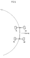
- VL front left
- VR front right
- HR rear right
- the front axle can now 10 or / and the rear axle 12 may be crossed.
- the front wheels and / or the rear wheels more or less strongly on or rebounded.
- FIG. 2 is a schematic representation of the drive-connected front 10 and Rear axle 12 of an all-terrain vehicle acc.
- Fig. 1 shown in the direction of travel, wherein both the front 10 and the rear axle 12 are crossed (diagonal crossing).
- the VR and HL wheels are rebounded.
- the VL and VR wheels are compressed.
- the spring travel is recorded in a manner known per se by means of a spring travel sensor on the individual wheels.
- 3a) to 3c) different wheel spring travel s a , s b , s c are shown for a wheel R, where s a means the zero position, s b describes a spring-loaded wheel and s c a spring-loaded wheel.
- the brake control intervention for the brake of each wheel is determined in a brake control unit 20. Will be present A DSC control unit is used, DSC being an abbreviation for Dynamic Stability Control stands. So far 20 different brake control units Input variables such as the steering angle, the brake pressure, the rotation rate, the wheel speed, etc. provided. These sizes are mostly used by sensors (Reference number 22) determined directly and forwarded to the brake control unit 20.
- the wheel spring travel s i in turn come from sensors 26 on the individual wheels VL, VR, HL, HR.
- this not only a target engine torque and influences an engine control 28, but also determines the brake pressures for the individual wheel brakes Mb1 - Mb4, the can then be realized on the individual wheel brakes 30.
- the wheel brakes are individually controlled according to the individual calculated wheel brake pressures and contribute to improved traction, especially when climbing and a downhill run, at.
- the Braking torque control and drive torque control can be independent of conventional sizes such as wheel slip, lateral acceleration, turning rate and Steering angle. This results in an improvement in traction a preventive braking torque control and an improvement in stability and Prevention of tipping during circular drives and lane change maneuvers. Also one can Improvement of engine braking torques through a targeted brake intervention lifting wheels can be reached when driving downhill.
- the surface quality can be determined by evaluating the spring travel frequency determine and classify the road (e.g. gravel or Bad way).
- the conventional ABS / ASC slip thresholds can be used with this information increase accordingly and thus on the specific lanes achieve higher braking performance or higher traction performance.
Landscapes
- Engineering & Computer Science (AREA)
- Transportation (AREA)
- Mechanical Engineering (AREA)
- Physics & Mathematics (AREA)
- Fluid Mechanics (AREA)
- Regulating Braking Force (AREA)
- Vehicle Body Suspensions (AREA)
Abstract
Description
- Fig. 1
- eine schematische Darstellung einer antriebsverbundenen Vorder- und Hinterachse eines Geländefahrzeugs in Draufsicht,
- Fig. 2
- eine schematische Darstellung wie Fig. 1, jedoch in Fahrtrichtung,
- Fig. 3a) bis 3c)
- schematische Darstellungen von Rädern mit verschiedenen Radausfederwegen,
- Fig. 4
- ein Blockdiagramm einer Schaltskizze einer Ausführungsform eines erfindungsgemäßen Steuersystems und
- Fig. 5
- eine schematische Darstellung einer antriebsverbundenen Vorder- und Hinderachse eines Geländefahrzeugs bei einer beschleunigten Kurvenfahrt.
Claims (9)
- Verfahren zur Bremseingriffsregelung bei einem allradangetriebenen Fahrzeug mit einem Bremsregelsystem umfassend eine Steuereinrichtung sowie den einzelnen Rädern zugeordnete und unabhängig voneinander beaufschlagbare Bremsen, wobei die Steuereinrichtung in Abhängigkeit von Eingangsinformationen Signale zur Ansteuerung der einzelnen Bremsen erzeugt,
dadurch gekennzeichnet,daß Radfederwege oder die Radaufstandskräfte an einzelnen Rädern erfaßt und aus den Radfederwegen, den Radaufstandskräften oder davon abgeleiteten Größen Radsignale erzeugt werden,daß die Radaignale der Steuereinrichtung zugeführt werden unddaß die Signale zur Ansteuerung der einzelnen Bremsen zumindest in Abhängigkeit von den als Eingangsinformationen vorliegenden, einzelnen Radsignalen generiert werden. - Verfahren nach Anspruch 1,
dadurch gekennzeichnet,daß eine verringerte Radaufstandskraft an einem Rad durch einen Bremseingriff derart ausgeglichen wird, daß ein Schlupf dieses Rades im wesentlichen verhindert ist. - Verfahren nach Anspruch 1 oder 2,
dadurch gekennzeichnet,daß die Radfederwege oder die Radaufstandskräfte mittels Sensoren bestimmt werden. - Verfahren nach einem der Ansprüche 1 bis 3,
dadurch gekennzeichnet,daß aus den Radfederwegen die Radaufstandskräfte ermittelt werden. - Verfahren nach einem der Ansprüche 1 bis 4,
dadurch gekennzeichnet,daß aus den zeitlichen Veränderungen der Radfederwege Ein- und Ausfederraten oder aus der zeitlichen Änderung der Radaufstandskräfte Radaufstandskraftraten ermittelt und zumindest eine dieser Größen als Radsignal verwendet werden. - Verfahren nach einem der vorhergehenden Ansprüche,
dadurch gekennzeichnet,daß der Steuereinrichtung als zusätzliche Eingangsgrößen Signale zugeführt werden, die eine Bergauf- oder Bergabfahrt angeben. - Verfahren nach Anspruch 6,
dadurch gekennzeichnet,daß die die Bergauf- oder Bergabfahrt beschreibenden Signale auch Informationen über die Steigung einer befahrenen Fläche enthalten. - Verfahren nach einem der vorhergehenden Ansprüche,
dadurch gekennzeichnet,daß der Steuereinrichtung als zusätzliche Eingangsgrößen Signale zugeführt werden, welche die Größe einer Querbeschleunigung des Fahrzeugs angeben. - Steuereinrichtung zur Bremseingriffsregelung bei einem allradangetriebenen Fahrzeug zur Durchführung eines der vorgenannten Verfahren 1 bis 8 mit Signaleingängen, über die Eingangsinformationen eingelesen werden, und Signalausgängen zur Ansteuerung von einzelnen Bremsen,
dadurch gekennzeichnet,daß als Eingangsinformationen Radsignale verarbeitbar sind, die Radfederwegen, Radaufstandskräften oder davon abgeleiteten Größen entsprechen,und daß Signale zur Ansteuerung der einzelnen Bremsen zumindest in Abhängigkeit von den Radsignalen generierbar sind.
Applications Claiming Priority (2)
| Application Number | Priority Date | Filing Date | Title |
|---|---|---|---|
| DE19946463A DE19946463C1 (de) | 1999-09-28 | 1999-09-28 | Verfahren zur Bremseingriffsregelung und Steuereinrichtung |
| DE19946463 | 1999-09-28 |
Publications (3)
| Publication Number | Publication Date |
|---|---|
| EP1088724A2 true EP1088724A2 (de) | 2001-04-04 |
| EP1088724A3 EP1088724A3 (de) | 2002-05-08 |
| EP1088724B1 EP1088724B1 (de) | 2010-05-12 |
Family
ID=7923582
Family Applications (1)
| Application Number | Title | Priority Date | Filing Date |
|---|---|---|---|
| EP00118065A Expired - Lifetime EP1088724B1 (de) | 1999-09-28 | 2000-08-23 | Verfahren zur Bremseingriffsregelung und Steuereinrichtung |
Country Status (5)
| Country | Link |
|---|---|
| US (1) | US6321155B1 (de) |
| EP (1) | EP1088724B1 (de) |
| JP (1) | JP2001114086A (de) |
| DE (2) | DE19946463C1 (de) |
| ES (1) | ES2342710T3 (de) |
Families Citing this family (10)
| Publication number | Priority date | Publication date | Assignee | Title |
|---|---|---|---|---|
| DE10107455A1 (de) * | 2000-06-02 | 2002-01-31 | Continental Teves Ag & Co Ohg | Verfahren und Regelungssystem zur Regelung des Radschlupfes |
| EP1317363B1 (de) | 2000-09-09 | 2015-05-20 | Kelsey-Hayes Company | Schlechtwegerkennung mit verwendung von daten des radaufhängungssystems |
| DE10045225A1 (de) | 2000-09-13 | 2002-03-28 | Bayerische Motoren Werke Ag | Bremseingriffs-Regelungsverfahren zur Verhinderung von Radschlupf |
| JP4342175B2 (ja) * | 2002-12-27 | 2009-10-14 | トヨタ自動車株式会社 | 制動システム |
| JP4244182B2 (ja) * | 2003-11-17 | 2009-03-25 | 本田技研工業株式会社 | アンチロックブレーキ制御方法 |
| DE102004008265A1 (de) * | 2004-02-20 | 2005-09-01 | Continental Aktiengesellschaft | Verfahren zur Antriebsschlupfregelung eines Kraftfahrzeugs |
| DE102014006191A1 (de) | 2014-04-30 | 2015-11-05 | Audi Ag | Verfahren zum Betreiben einer Fahrerassistenzeinrichtung für ein Kraftfahrzeug sowie entsprechende Fahrerassistenzeinrichtung |
| DE102016015268B4 (de) * | 2016-12-21 | 2019-06-06 | Compagnie Générale Des Etablissements Michelin | Verfahren zur Ansteuerung einer Fahrzeugbremsanlage zur Optimierung des Bremsvorganges |
| DE102018202920A1 (de) * | 2018-02-27 | 2019-08-29 | Continental Teves Ag & Co. Ohg | Verfahren zum Betrieb eines sicherheitsrelevanten Fahrzeugsystems |
| KR102842930B1 (ko) * | 2020-03-09 | 2025-08-07 | 현대자동차주식회사 | 차량의 휠슬립 제어 장치 및 그 방법 |
Family Cites Families (9)
| Publication number | Priority date | Publication date | Assignee | Title |
|---|---|---|---|---|
| DE3534211A1 (de) * | 1985-09-25 | 1987-03-26 | Pfister Gmbh | Kraftfahrzeug und verfahren zu dessen betrieb |
| JP2618250B2 (ja) * | 1987-12-22 | 1997-06-11 | 富士重工業株式会社 | トラクション制御装置 |
| JPH03258650A (ja) * | 1990-03-09 | 1991-11-18 | Toyota Motor Corp | 路面摩擦係数検出装置 |
| JP2917652B2 (ja) * | 1991-06-10 | 1999-07-12 | 株式会社デンソー | サスペンション制御装置 |
| GB9214543D0 (en) * | 1992-07-08 | 1992-08-19 | Lotus Car | A vehicle suspension control system |
| JP3099675B2 (ja) * | 1995-04-06 | 2000-10-16 | トヨタ自動車株式会社 | 車両挙動制御システム |
| JP3034453B2 (ja) * | 1995-11-20 | 2000-04-17 | トヨタ自動車株式会社 | アンチロックブレーキ制御装置 |
| DE69722562T2 (de) * | 1996-07-24 | 2004-05-06 | Denso Corp., Kariya | Regelsystem für einen Fahrzeugbewegungszustand |
| DE19704954A1 (de) * | 1997-02-10 | 1998-08-13 | Itt Mfg Enterprises Inc | Verfahren zur verbesserten Bestimmung eines Raddrehzahlsignales und/oder eines Schlupfsignales |
-
1999
- 1999-09-28 DE DE19946463A patent/DE19946463C1/de not_active Expired - Fee Related
-
2000
- 2000-08-23 EP EP00118065A patent/EP1088724B1/de not_active Expired - Lifetime
- 2000-08-23 DE DE50015925T patent/DE50015925D1/de not_active Expired - Lifetime
- 2000-08-23 ES ES00118065T patent/ES2342710T3/es not_active Expired - Lifetime
- 2000-09-27 JP JP2000294344A patent/JP2001114086A/ja active Pending
- 2000-09-28 US US09/671,155 patent/US6321155B1/en not_active Expired - Lifetime
Also Published As
| Publication number | Publication date |
|---|---|
| JP2001114086A (ja) | 2001-04-24 |
| US6321155B1 (en) | 2001-11-20 |
| DE50015925D1 (de) | 2010-06-24 |
| EP1088724B1 (de) | 2010-05-12 |
| DE19946463C1 (de) | 2001-04-05 |
| EP1088724A3 (de) | 2002-05-08 |
| ES2342710T3 (es) | 2010-07-13 |
Similar Documents
| Publication | Publication Date | Title |
|---|---|---|
| EP2146880B1 (de) | Verfahren und vorrichtung zur stabilisierung eines einspurigen kraftfahrzeugs | |
| DE10340629A1 (de) | Giersteuerung für ein Kraftfahrzeug mit Lenk-Stellgliedern | |
| EP1439103B1 (de) | Verfahren zur Fahrdynamikregelung für einen Fahrzeugzug | |
| EP1334017A1 (de) | Verfahren zur regelung der fahrstabilität | |
| DE19827882A1 (de) | Verfahren und Vorrichtung zur Stabilisierung eines Fahrzeugs | |
| EP1601561A2 (de) | Verfahren und system zur regelung der fahrstabilität eines fahrzeugs und verwendung des systems | |
| DE102006012246A1 (de) | Verfahren und Regelsystem zum Stabilisieren eines Fahrzeugs | |
| EP1914141A1 (de) | Bedienkonzept zum Einstellen verschiedener Fahrdynamik-Charakteristika an einem Fahrzeug | |
| EP1088724B1 (de) | Verfahren zur Bremseingriffsregelung und Steuereinrichtung | |
| EP1606156A1 (de) | Lenkvorrichtung für fahrzeuge mit einem frei durch seitenkräfte lenkbaren radpaar | |
| EP3990336A1 (de) | Verfahren und vorrichtung zum stabilisieren eines anhängergespanns sowie steuergerät | |
| DE10031128B4 (de) | Verfahren und Vorrichtung zur Erkennung eines Spurwechsels | |
| DE102008034908A1 (de) | Verfahren zur Stabilisierung eines Fahrzeuges bei Aquaplaning | |
| DE19944333B4 (de) | Vorrichtung zur Regelung eines Giermoments | |
| DE112021004306T5 (de) | Radaufhängungssteuervorrichtung, fahrzeug und radaufhängungssteuerverfahren | |
| EP1070623B1 (de) | Verfahren zur Antriebsschlupfregelung | |
| DE19955512B4 (de) | Verfahren und Vorrichtung zur Einstellung der Bremswirkung an den Rädern eines Kraftfahrzeugs | |
| DE10325486A1 (de) | Verfahren zur Regelung der Fahrstabilität | |
| EP0999962B1 (de) | Verfahren und vorrichtung zur erkennung einer bremssituation bei kurvenfahrt und mit mu-split | |
| DE10316253B4 (de) | Verfahren zum Modifizieren einer Fahrstabilitätsregelung eines Fahrzeugs | |
| EP1306288A2 (de) | Verfahren zum Stabilisieren eines Mehrspur-Kraftfahrzeugs | |
| DE102004032720B4 (de) | Bremskraftverteiler für Kraftfahrzeuge und Verfahren zur Begrenzung der Bremskraft | |
| DE10039108A1 (de) | Verfahren und Vorrichtung zum Bestimmen von Fahrzeugzustandsgrößen | |
| DE102006044425B4 (de) | Verfahren zur Kippstabilisierung von Kraftfahrzeugen | |
| EP1587722B1 (de) | Verfahren zur erhöhung der fahrstabilität |
Legal Events
| Date | Code | Title | Description |
|---|---|---|---|
| PUAI | Public reference made under article 153(3) epc to a published international application that has entered the european phase |
Free format text: ORIGINAL CODE: 0009012 |
|
| AK | Designated contracting states |
Kind code of ref document: A2 Designated state(s): AT BE CH CY DE DK ES FI FR GB GR IE IT LI LU MC NL PT SE |
|
| AX | Request for extension of the european patent |
Free format text: AL;LT;LV;MK;RO;SI |
|
| PUAL | Search report despatched |
Free format text: ORIGINAL CODE: 0009013 |
|
| AK | Designated contracting states |
Kind code of ref document: A3 Designated state(s): AT BE CH CY DE DK ES FI FR GB GR IE IT LI LU MC NL PT SE |
|
| AX | Request for extension of the european patent |
Free format text: AL;LT;LV;MK;RO;SI |
|
| 17P | Request for examination filed |
Effective date: 20021018 |
|
| AKX | Designation fees paid |
Designated state(s): DE ES FR GB IT SE |
|
| 17Q | First examination report despatched |
Effective date: 20070426 |
|
| GRAP | Despatch of communication of intention to grant a patent |
Free format text: ORIGINAL CODE: EPIDOSNIGR1 |
|
| GRAS | Grant fee paid |
Free format text: ORIGINAL CODE: EPIDOSNIGR3 |
|
| GRAA | (expected) grant |
Free format text: ORIGINAL CODE: 0009210 |
|
| AK | Designated contracting states |
Kind code of ref document: B1 Designated state(s): DE ES FR GB IT SE |
|
| REG | Reference to a national code |
Ref country code: GB Ref legal event code: FG4D Free format text: NOT ENGLISH |
|
| REF | Corresponds to: |
Ref document number: 50015925 Country of ref document: DE Date of ref document: 20100624 Kind code of ref document: P |
|
| REG | Reference to a national code |
Ref country code: ES Ref legal event code: FG2A Ref document number: 2342710 Country of ref document: ES Kind code of ref document: T3 |
|
| REG | Reference to a national code |
Ref country code: SE Ref legal event code: TRGR |
|
| PLBE | No opposition filed within time limit |
Free format text: ORIGINAL CODE: 0009261 |
|
| STAA | Information on the status of an ep patent application or granted ep patent |
Free format text: STATUS: NO OPPOSITION FILED WITHIN TIME LIMIT |
|
| 26N | No opposition filed |
Effective date: 20110215 |
|
| REG | Reference to a national code |
Ref country code: DE Ref legal event code: R097 Ref document number: 50015925 Country of ref document: DE Effective date: 20110214 |
|
| REG | Reference to a national code |
Ref country code: FR Ref legal event code: PLFP Year of fee payment: 16 |
|
| PGFP | Annual fee paid to national office [announced via postgrant information from national office to epo] |
Ref country code: ES Payment date: 20150720 Year of fee payment: 16 Ref country code: DE Payment date: 20150801 Year of fee payment: 16 Ref country code: GB Payment date: 20150827 Year of fee payment: 16 |
|
| PGFP | Annual fee paid to national office [announced via postgrant information from national office to epo] |
Ref country code: SE Payment date: 20150811 Year of fee payment: 16 Ref country code: FR Payment date: 20150827 Year of fee payment: 16 |
|
| PGFP | Annual fee paid to national office [announced via postgrant information from national office to epo] |
Ref country code: IT Payment date: 20150825 Year of fee payment: 16 |
|
| REG | Reference to a national code |
Ref country code: DE Ref legal event code: R119 Ref document number: 50015925 Country of ref document: DE |
|
| REG | Reference to a national code |
Ref country code: SE Ref legal event code: EUG |
|
| GBPC | Gb: european patent ceased through non-payment of renewal fee |
Effective date: 20160823 |
|
| PG25 | Lapsed in a contracting state [announced via postgrant information from national office to epo] |
Ref country code: SE Free format text: LAPSE BECAUSE OF NON-PAYMENT OF DUE FEES Effective date: 20160824 |
|
| REG | Reference to a national code |
Ref country code: FR Ref legal event code: ST Effective date: 20170428 |
|
| PG25 | Lapsed in a contracting state [announced via postgrant information from national office to epo] |
Ref country code: GB Free format text: LAPSE BECAUSE OF NON-PAYMENT OF DUE FEES Effective date: 20160823 Ref country code: FR Free format text: LAPSE BECAUSE OF NON-PAYMENT OF DUE FEES Effective date: 20160831 Ref country code: DE Free format text: LAPSE BECAUSE OF NON-PAYMENT OF DUE FEES Effective date: 20170301 |
|
| PG25 | Lapsed in a contracting state [announced via postgrant information from national office to epo] |
Ref country code: IT Free format text: LAPSE BECAUSE OF NON-PAYMENT OF DUE FEES Effective date: 20160823 |
|
| REG | Reference to a national code |
Ref country code: ES Ref legal event code: FD2A Effective date: 20180507 |
|
| PG25 | Lapsed in a contracting state [announced via postgrant information from national office to epo] |
Ref country code: ES Free format text: LAPSE BECAUSE OF NON-PAYMENT OF DUE FEES Effective date: 20160824 |