EP1087708B1 - Procede de generation d'un train impulsionnel d'un jet liquide sterile pour des applications medicales - Google Patents
Procede de generation d'un train impulsionnel d'un jet liquide sterile pour des applications medicales Download PDFInfo
- Publication number
- EP1087708B1 EP1087708B1 EP99925126A EP99925126A EP1087708B1 EP 1087708 B1 EP1087708 B1 EP 1087708B1 EP 99925126 A EP99925126 A EP 99925126A EP 99925126 A EP99925126 A EP 99925126A EP 1087708 B1 EP1087708 B1 EP 1087708B1
- Authority
- EP
- European Patent Office
- Prior art keywords
- previous
- suction
- communication
- liquid
- pressure
- Prior art date
- Legal status (The legal status is an assumption and is not a legal conclusion. Google has not performed a legal analysis and makes no representation as to the accuracy of the status listed.)
- Expired - Lifetime
Links
- 239000007788 liquid Substances 0.000 title claims abstract description 78
- 238000000034 method Methods 0.000 title claims abstract description 55
- 238000004891 communication Methods 0.000 claims abstract description 25
- 230000000737 periodic effect Effects 0.000 claims abstract description 18
- 230000000694 effects Effects 0.000 claims description 6
- 238000002224 dissection Methods 0.000 claims description 4
- 238000007599 discharging Methods 0.000 claims description 3
- 238000002955 isolation Methods 0.000 claims 1
- 230000008569 process Effects 0.000 abstract description 21
- 238000010304 firing Methods 0.000 abstract description 11
- 238000005273 aeration Methods 0.000 abstract 1
- 238000013022 venting Methods 0.000 description 15
- 239000004744 fabric Substances 0.000 description 8
- 230000006870 function Effects 0.000 description 6
- 230000008901 benefit Effects 0.000 description 4
- 239000000463 material Substances 0.000 description 4
- 230000001960 triggered effect Effects 0.000 description 4
- 230000006837 decompression Effects 0.000 description 3
- 230000003749 cleanliness Effects 0.000 description 2
- 230000000052 comparative effect Effects 0.000 description 2
- 230000007423 decrease Effects 0.000 description 2
- 230000002950 deficient Effects 0.000 description 2
- 239000012530 fluid Substances 0.000 description 2
- 239000012528 membrane Substances 0.000 description 2
- 210000000056 organ Anatomy 0.000 description 2
- 230000003252 repetitive effect Effects 0.000 description 2
- 230000000630 rising effect Effects 0.000 description 2
- 238000012163 sequencing technique Methods 0.000 description 2
- 240000008042 Zea mays Species 0.000 description 1
- 230000003416 augmentation Effects 0.000 description 1
- 230000015572 biosynthetic process Effects 0.000 description 1
- 238000004140 cleaning Methods 0.000 description 1
- 210000004087 cornea Anatomy 0.000 description 1
- 230000032798 delamination Effects 0.000 description 1
- 230000001419 dependent effect Effects 0.000 description 1
- 238000009795 derivation Methods 0.000 description 1
- 230000037213 diet Effects 0.000 description 1
- 235000005911 diet Nutrition 0.000 description 1
- 238000004945 emulsification Methods 0.000 description 1
- 230000008571 general function Effects 0.000 description 1
- 230000006872 improvement Effects 0.000 description 1
- 230000003472 neutralizing effect Effects 0.000 description 1
- 230000035515 penetration Effects 0.000 description 1
- 230000000750 progressive effect Effects 0.000 description 1
- 230000010349 pulsation Effects 0.000 description 1
- 238000011084 recovery Methods 0.000 description 1
- 230000002787 reinforcement Effects 0.000 description 1
- 230000029058 respiratory gaseous exchange Effects 0.000 description 1
- 230000035939 shock Effects 0.000 description 1
- 239000007787 solid Substances 0.000 description 1
- 239000007921 spray Substances 0.000 description 1
- 238000001356 surgical procedure Methods 0.000 description 1
- 230000001360 synchronised effect Effects 0.000 description 1
Images



Classifications
-
- A—HUMAN NECESSITIES
- A61—MEDICAL OR VETERINARY SCIENCE; HYGIENE
- A61B—DIAGNOSIS; SURGERY; IDENTIFICATION
- A61B17/00—Surgical instruments, devices or methods
- A61B17/32—Surgical cutting instruments
- A61B17/3203—Fluid jet cutting instruments
-
- A—HUMAN NECESSITIES
- A61—MEDICAL OR VETERINARY SCIENCE; HYGIENE
- A61M—DEVICES FOR INTRODUCING MEDIA INTO, OR ONTO, THE BODY; DEVICES FOR TRANSDUCING BODY MEDIA OR FOR TAKING MEDIA FROM THE BODY; DEVICES FOR PRODUCING OR ENDING SLEEP OR STUPOR
- A61M1/00—Suction or pumping devices for medical purposes; Devices for carrying-off, for treatment of, or for carrying-over, body-liquids; Drainage systems
- A61M1/71—Suction drainage systems
- A61M1/77—Suction-irrigation systems
-
- A—HUMAN NECESSITIES
- A61—MEDICAL OR VETERINARY SCIENCE; HYGIENE
- A61M—DEVICES FOR INTRODUCING MEDIA INTO, OR ONTO, THE BODY; DEVICES FOR TRANSDUCING BODY MEDIA OR FOR TAKING MEDIA FROM THE BODY; DEVICES FOR PRODUCING OR ENDING SLEEP OR STUPOR
- A61M1/00—Suction or pumping devices for medical purposes; Devices for carrying-off, for treatment of, or for carrying-over, body-liquids; Drainage systems
- A61M1/71—Suction drainage systems
- A61M1/74—Suction control
- A61M1/75—Intermittent or pulsating suction
Definitions
- the invention relates to a method of generating a pulse train of a liquid jet sterile pulsed-aspirated and pulsed-suctioned liquid jet thus generated for feeding a handpiece or a catheter for particular applications surgical and medical.
- EP may be mentioned n ° 0636345 in the name of SENTINEL MEDICAL concerning a pulsed jet surgical instrument of liquid to cutting and emulsification purposes with a joint suction for the evacuation of the liquid and biological residues.
- the pulsed jet comes from the movement of back and forth repeated an amplifier piston that receives the liquid under low pressure.
- suction is also continuous and separate. However, he does not This is not cutting but delamination and disintegration for the evacuation of materials and troublesome tissues.
- pulsed liquid jets previously known high-pressure liquid pulse trains triggered to order and projected on the dissection area.
- the liquid spray is then evacuated by suction continuously or when it exceeds a certain quantity considered inconvenient for the continuation of the dissection work.
- the dissection yield is only slightly better than that of a jet continuous because of rebound phenomena.
- DE-A-37 15 418 shows a process as defined in the introductory part of claim 1.
- the present invention aims to remedy the aforementioned drawbacks by proposing a method of generating a pulse train of a liquid jet sterile pulsed-aspirated for feeding a handpiece, a catheter or the like, for use surgical or medical.
- the process according to the invention is defined by claim 1.
- the dependent claims relate to variants of the process according to the invention. This process allows to create a jet ejected and sucked from a high operative efficiency.
- the invention relates to a circuit according to claim 25 for the implementation process according to the invention.
- This circuit is characterized in that one puts in works a liquid way under pressure for example under high pressure and a pneumatic way suction and in that we order periodically firing the jet under pressure during the periodic application of aspiration and in this that the fabric is released during the cut of suction by venting.
- the method according to the invention has many advantages.
- the fabric Being a pulsed-aspirated jet, that is to say a shot fired at the same time as works the suction, the fabric remains plated, that is to say stretched momentarily before and during the shot at the end of the end sleeve of the piece to hand, then relaxes during the final phase of aspiration. This is a shot on a fabric stretched which ensures precision and cleanliness of the cut and the operative field.
- the variant of the basic process aims to remedy these disadvantages.
- the inventive principle of this variant is to get a falling edge of the slots pressure of the jet of liquid not only by the pressure cut and therefore that of the jet, but by a simultaneous or almost simultaneous communication simultaneous liquid supply line with outside especially in the air or with the suction or the vacuum generator.
- the variant of the basic process provides, bypass on the feed tube in pressurized liquid, a connected duct branch to the vacuum generator or to the air through a frequency-controlled cut-opening device recurrence in synchronism with others controls, so as to achieve, before shooting following, the discharge of the residual pressure existing in the liquid supply duct under pressure.
- This periodic order for implementation communication of the pressure conduit with the outside occurs simultaneously or immediately before or after the cut command of the conduit high pressure supply.
- the basic process according to the invention consists, using all appropriate means, mechanical, electrical, electromechanical, electromagnetic or other, to generate on command from a first conduit carrying a liquid sterile under pressure delivered by a generator and of a second pneumatic suction duct, a impulse train of a sterile pulsed-aspirated liquid jet and project it through a handpiece for surgical applications or medical.
- a closing-opening means sequential flow rate according to the same frequency but with an opening time that can be different for the two fluids.
- the firing of the liquid jet under pressure is carried out during suction time intervals that is to say during the opening time of the closing-opening means of the suction duct.
- the process is completed in that one neutralizes vacuum aspiration air just after closing the duct suction, for example by venting the suction line to stop aspiration.
- the basic process can be implemented by simple means, such as means electromechanical actuators or others acting in pinching or crushing on a flexible duct conveying the liquid or the air sucked or by hydraulic break components such as flow shutters or solenoid valves, all controlled by an electronic circuit of sequencing.
- venting is carried out by the suction duct for example by a derivation of it periodically open and closed, but any other way to compensate for the strength Sucking to relax the fabric is possible.
- the shot with some delay in relation to the beginning of aspiration.
- the shot is from preferably in the first half of the width of aspiration impulse and stops preferably before the start of the second half. Breathing takes place after cutting off the suction and preference but not necessarily right after this cut.
- the breather is short-lived and follows quickly the end of aspiration.
- the rising edges of the impulses are vertical representations.
- the slope will depend on the type of closing-opening device flow rate used and in particular its inertia.
- the frequency of recurrence of the diet impulse and pulse width are modifiable. We can thus perform changes must according to the application surgical, namely the type of intervention, target organ or tissue and depth of intervention in the human body.
- the device generating this pulse train will allow to vary these main parameters including time parameters.
- the frequency of recurrence F R may for example be in a range between a fraction of Hertz and some Hertz, for example between 0.1 and 10 Hz.
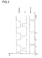
- Figure 2 shows waveforms based on the same principle of a liquid jet under pressure pulsed-aspirated, object of the basic process according to the invention.
- the duration of the shot and the suction duration increase simultaneously.
- the control pulses or the openings corresponding to the venting move on the time axis to start just after cutting the suction.
- Figure 3 shows waveforms without venting.
- This sample application is the one of an open end sleeve handpiece on its periphery for which the loosening of the fabric after the shooting is done automatically after the cut off the suction.
- Figure 4 is intended to illustrate the problem solved by the variant of the basic process.
- This ramp delimits, with the ideal vertical rear edge, a zone of inefficiency represented hatched, the extent of which increases with the frequency of recurrence F R.
- the impulse enlarges in width by a rear extension and the pressure cut is no longer frank but becomes progressive.
- the present improvement aims to remedy this drawback by correcting the deformation of the trailing edge of the pulse of pressure by a controlled decompression or automatic liquid supply tube pressure of the handpiece. This decompression is synchronized with the pressure pulses.
- This variant of the basic process proceeds from the general inventive idea which consists in generating a pulse train of a pulsed liquid jet with suction in which the feed pipe of the liquid pressure generator is put in periodic communication with a vacuum generator or with the air to give rise to a pulsation regime of liquid ejection by a handpiece with a recurrence frequency F R , in which the rear edge of the liquid pressure pulse is obtained by cutting off the supply of pressurized liquid and discharging residual pressure remaining or remaining in the supply line of the handpiece in pressurized liquid by placing the conduit in communication with the outside.
- a particularly sterile fluid generator under pressure GHP is connected to a handpiece 1 or PAM, for example surgical, by a tubular supply pressure 2 through a cut-opening member 3 controlled from periodically at a recurrence frequency F R.
- the liquid under pressure is, for example, generated and ejected at a pressure between 15 and 100 bar depending on the intended application.
- a suction circuit comprises a GDP depression generator connected to the handpiece 1 by an independent suction duct 4 through an isolation-communication element 5 controlled at the recurrence frequency F R in synchronism with the control in cut-opening of the tubular supply pipe 2 in liquid under pressure by the cutoff-opening member 3.
- a venting device (not shown) is grafted onto the suction duct. It is controlled in synchronism with the other commands at the recurrence frequency F R. This venting device aims to neutralize the suction and thus relax the fabric just before a new shot.
- this branch derivative 6 is that of periodically setting the supply duct 2 in liquid under pressure in communication with the outside. More particularly this function is that of decompressing, that is to say quickly evacuate the residual pressure, immediately before or after or at the close of supply duct 2 in liquid under pressure.
- one of the decompression means possible is the connection to a GDP depression generator, which may be the same as that of the suction circuit, and this at through a switch device 7 ensuring the ordered opening and closing of the communication with this generator GDP and this in synchronism with the control of the jet under pressure.
- valve ordered or a permeable membrane or any other similar means we quote a valve ordered or a permeable membrane or any other similar means.
- the residual pressure can also until some frequency be evacuated so simple and automatic by an adjacent exit connected to a MALA device with a pressure threshold or having a constant periodic delay to the opening.
- outside in its most general sense, that is to say a space or volume outside the duct 2.
- it may also be a buffer volume, an extensible closed volume, a flexible membrane ...
- shooting takes place during the suction, that is to say that the pulse of pressure is triggered and cut in the meantime of time corresponding to a niche of depression.
- FIG. 10 shows the command air venting is carried out just after cutting off the suction to favor detachment and relaxation of tissues.
- the second part of Figure 10 illustrates control of the end of the shot by aspiration.
- the pressure pulse of the shot at the end of the handpiece without correction is the one represented on the third curve leaving appear the zone of inefficiency represented hatched.
- the cut is controlled of the firing pulse by the depression before it normal cut by the opening-closing member 3.
- the pressure pulse starting at the time t1 is cut in advance at time t2 by an opening fast command of communication with the outside and especially with suction.
- We calibrate the firing pulse at a duration T by performing a sharp and straight cut as it appears on the last waveform shown in this figure 10.
- the duration of the depression impulse or suction of the fire pressure duct which triggers the cut (4th curve) is sufficient to realize the total discharge of the pressure residual. It remains weak, however.
- the depression or aspiration impulse has purpose of creating a liquid call and therefore a discharge before or just before the break of the liquid pressure, thus neutralizing the afterglow pressure and guaranteeing an abrupt fall of the pressure.
- the present invention is implemented by a source of liquid under pressure and by a sequencing apparatus that is to say stop and sudden start of the liquid jet under pressure feeding a handpiece or catheter.
- impulses can come repetitive mechanical actions for example on a flexible conduit.
- the pulse train triggered by the operator continues at the recurrence frequency F R until the manual stop command ordered by the operator.
Landscapes
- Health & Medical Sciences (AREA)
- Heart & Thoracic Surgery (AREA)
- Life Sciences & Earth Sciences (AREA)
- General Health & Medical Sciences (AREA)
- Surgery (AREA)
- Veterinary Medicine (AREA)
- Engineering & Computer Science (AREA)
- Biomedical Technology (AREA)
- Public Health (AREA)
- Animal Behavior & Ethology (AREA)
- Anesthesiology (AREA)
- Hematology (AREA)
- Vascular Medicine (AREA)
- Nuclear Medicine, Radiotherapy & Molecular Imaging (AREA)
- Pulmonology (AREA)
- Medical Informatics (AREA)
- Molecular Biology (AREA)
- Surgical Instruments (AREA)
- Medicines That Contain Protein Lipid Enzymes And Other Medicines (AREA)
- Eyeglasses (AREA)
- External Artificial Organs (AREA)
Description
- front arrière de l'impulsion de pression marquant l'arrêt bien raide lorsque la fréquence de récurrence augmente ;
- efficacité et propreté dans le travail chirurgical ;
- perfectionnement très facile à mettre en oeuvre.
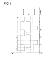
- la figure 1 est un graphique des formes d'ondes de base des paramètres du train impulsionnel en fonction du temps ;
- la figure 2 est un graphique des formes d'ondes selon une première variante à durée de tir plus importante ;
- la figure 3 est un graphique des formes d'ondes de tirs ne faisant pas intervenir de mise à l'air ;
- la figure 4 est une représentation graphique comparative de trois trains d'impulsions de pression P de liquide en fonction du temps « t » à fréquences de récurrence FR croissantes montrant la zone d'inefficacité du procédé de base grandissant avec l'augmentation de la fréquence de récurrence ;
- la figure 5 est une vue du montage de base montrant les liaisons avec les différentes sources et les emplacements des organes de coupure-ouverture en utilisant un générateur de dépression GDP ;
- les figures 6 et 7 sont des vues analogues mais avec une liaison à un dispositif de mise à l'air commandé MALC ou automatique MALA ;
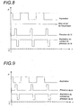
- la figure 8 est un graphique des formes d'ondes des différentes grandeurs en pression P formant le jet pulsé représentées en fonction du temps « t » avec mise périodique à l'air ;
- la figure 9 est un graphique des formes d'ondes des différentes grandeurs en pression P formant le jet pulsé représentées en fonction du temps « t » sans mise périodique à l'air ;
- la figure 10 est un graphique des formes d'ondes des différentes grandeurs en pression P formant le jet pulsé représentées en fonction du temps « t » avec commande du front arrière de chute de pression à partir de l'aspiration.
- phase 1 : début de l'aspiration,
- phase 2 : tir du jet sous pression pendant une courte durée à l'intérieur de l'impulsion d'aspiration,
- phase 3 : poursuite de l'aspiration après le tir,
- phase 4 : mise à l'air pendant la coupure de l'aspiration,
- phase 5 : poursuite de la coupure de l'aspiration jusqu'à la prochaine période.
- fréquence de récurrence (FR) : 1 Hz
- largeur d'impulsion de tir : 100 ms
- largeur d'impulsion d'aspiration : 400 ms
- repos d'aspiration : 600 ms
- largeur d'impulsion de mise à l'air: 300 ms
- décalage entre la fin de l'impulsion d'aspiration et la mise à l'air : faible.
Claims (29)
- Procédé de génération sur commande d'un train impulsionnel d'un jet pulsé de liquide pour une pièce à main en vue notamment d'un travail chirurgical de dissection, le travail chirurgical s'effectuant par des trains d'impulsions périodiques d'un liquide sous pression formés chacun par une succession de commandes périodiques en ouverture et en fermeture du liquide sous pression selon une fréquence de récurrence FR pour former des impulsions de pression constituant des tirs de jets élémentaires de liquide sous pression mettant en oeuvre une voie de liquide sous pression provenant d'un générateur de liquide sous pression GHP et un train d'impulsions périodiques de dépression mettant en oeuvre une voie d'aspiration reliée à une source de dépression GDP, les impulsions de pression et les impulsions de dépression présentant la même fréquence de récurrence FR, caractérisé en ce que :les impulsions de pression sont inférieures en durée aux impulsions de dépression,les impulsions de pression sont situées temporellement à l'intérieur des impulsions de dépression et s'effectuent avec un certain retard par rapport an début des impulsions de dépression, créant ainsi un jet pulsé-aspiré.
- Procédé selon la revendication 1 caractérisé en ce que le liquide sous pression est généré et expulsé sous haute pression.
- Procédé selon la revendication précédente caractérisé en ce que la haute pression est située entre 15 et 100 bars.
- Procédé selon l'une quelconque des revendications précédentes caractérisé en ce que l'on commande le tir périodique du jet sous pression dans la première moitié de la durée périodique d'application de l'aspiration.
- Procédé selon la revendication précédente caractérisé en ce que la durée périodique de tir du jet sous pression se termine avant la première moitié de l'impulsion périodique d'aspiration.
- Procédé selon l'une quelconque des revendications précédentes caractérisé en ce que l'aspiration est suivie après sa coupure par une compensation de l'effet de succion pour détendre le tissu.
- Procédé selon la revendication précédente caractérisé en ce que la compensation de l'effet de succion est une mise à l'air pendant la coupure de l'aspiration.
- Procédé selon la revendication précédente caractérisé en ce que l'on procède à la mise à l'air par le conduit d'aspiration.
- Procédé selon l'une quelconque des revendications précédentes caractérisé en ce que la fréquence de récurrence FR est modifiable.
- Procédé selon l'une quelconque des revendications précédentes caractérisé en ce que la fréquence de récurrence FR est située dans une gamme comprise entre une fraction de Hertz et quelques Hertz.
- Procédé selon la revendication précédente caractérisé en ce que la fréquence de récurrence FR est comprise entre 0,1 et 10 Hz.
- Procédé selon la revendication précédente caractérisé en ce que la fréquence de récurrence FR est de 1 Hz.
- Procédé selon l'une quelconque des revendications précédentes caractérisé en ce que le front arrière de l'impulsion de pression P est obtenu en déchargeant, au voisinage du moment de la coupure de l'alimentation en liquide sous pression, le conduit d'alimentation (2) en liquide sous pression de la pièce à main PAM par une mise en communication avec l'extérieur de ce conduit (2).
- Procédé selon la revendication 13 caractérisé en ce que la mise en communication avec l'extérieur est une mise en communication avec un générateur de dépression GDP.
- Procédé selon la revendication 13, caractérisé en ce que la mise en communication avec l'extérieur est une mise à l'air.
- Procédé selon la revendication 13 caractérisé en ce que la mise en communication avec l'extérieur qui s'effectue au voisinage du moment de la coupure est une décharge dans un volume tampon.
- Procédé selon la revendication 13 caractérisé en ce que la mise en communication avec l'extérieur qui s'effectue au voisinage du moment de la coupure est une décharge dans un volume fermé extensible.
- Procédé selon l'une quelconque des revendications 13 à 17 caractérisé en ce que la mise en communication avec l'extérieur s'effectue un peu avant la coupure.
- Procédé selon l'une quelconque des revendications 13 à 17 caractérisé en ce que la mise en communication avec l'extérieur s'effectue au moment de la coupure.
- Procédé selon l'une quelconque des revendications 13 à 17 caractérisé en ce que la mise en communication avec l'extérieur s'effectue un peu après la coupure.
- Procédé selon l'une quelconque des revendications 13 à 20 caractérisé en ce que la durée de l'aspiration déchargeant le tube d'alimentation (2) est faible par rapport à la durée entre le front arrière de l'impulsion de pression et le front avant de la prochaine impulsion de pression.
- Procédé selon les revendications 13 et 14 caractérisé en ce que l'on commande la coupure de l'impulsion de pression de liquide par la commande de la mise en communication avec le générateur de dépression GDP.
- Procédé selon l'une quelconque des revendications précédentes caractérisé en ce que l'on commande un nombre défini de jets élémentaires de liquide sous pression.
- Procédé selon l'une quelconque des revendications précédentes caractérisé en ce que l'on commande un seul jet élémentaire de liquide sous pression à la fois.
- Circuit pour la mise en oeuvre du procédé selon l'une quelconque des revendications précédentes composé d'une pièce à main, d'un générateur de pression d'un liquide GHP, d'une liaison tubulaire par un conduit (2) pour l'alimentation en liquide sous pression de la pièce à main (1), d'un générateur de dépression GDP relié à la pièce à main par un conduit séparé (4), d'un organe (3) de coupure-ouverture du passage du liquide sous pression et d'un organe d'isolement et de mise en communication (5) du conduit (4) avec le générateur de dépression GDP, caractérisé en ce que le tube d'alimentation (2) de la pièce à main (1) en liquide sous pression présente une branche dérivée (6) pour la liaison avec l'extérieur.
- Circuit selon la revendication précédente caractérisé en ce que la branche dérivée (6) est raccordée à un générateur de dépression GDP à travers un organe d'isolement-communication (7) commandé en synchronisme avec la commande en ouverture-fermeture du conduit (2) d'alimentation de la pièce à main (1) en liquide sous pression.
- Circuit selon la revendication 25 caractérisé en ce que la branche dérivée (6) est raccordée à un dispositif de mise à l'air commandé MALC à travers un organe d'isolement-communication (7) commandé en synchronisme avec la commande en ouverture-fermeture du conduit (2) d'alimentation de la pièce à main (1) en liquide sous pression.
- Circuit selon la revendication 25 caractérisé en ce que la branche dérivée (6) est raccordée à un dispositif de mise à l'air automatique MALA.
- Circuit selon la revendication 26 caractérisé en ce que le générateur de dépression GDP est unique.
Applications Claiming Priority (5)
| Application Number | Priority Date | Filing Date | Title |
|---|---|---|---|
| FR9807879 | 1998-06-19 | ||
| FR9807879A FR2779935B1 (fr) | 1998-06-19 | 1998-06-19 | Procede de generation d'un train impulsionnel d'un jet liquide sterile pulse-aspire et jet pulse ainsi produit pour une piece a main en vue d'applications chirurgicales |
| FR9903630A FR2791250B1 (fr) | 1999-03-22 | 1999-03-22 | Procede ameliore de generation d'un jet pulse de liquide en vue d'applications chirurgicales, medicales et autres |
| FR9903630 | 1999-03-22 | ||
| PCT/FR1999/001462 WO1999065408A1 (fr) | 1998-06-19 | 1999-06-17 | Procede de generation d'un train impulsionnel d'un jet liquide sterile pour des applications medicales |
Publications (2)
| Publication Number | Publication Date |
|---|---|
| EP1087708A1 EP1087708A1 (fr) | 2001-04-04 |
| EP1087708B1 true EP1087708B1 (fr) | 2005-09-07 |
Family
ID=26234392
Family Applications (1)
| Application Number | Title | Priority Date | Filing Date |
|---|---|---|---|
| EP99925126A Expired - Lifetime EP1087708B1 (fr) | 1998-06-19 | 1999-06-17 | Procede de generation d'un train impulsionnel d'un jet liquide sterile pour des applications medicales |
Country Status (7)
| Country | Link |
|---|---|
| US (1) | US6423028B1 (fr) |
| EP (1) | EP1087708B1 (fr) |
| JP (1) | JP2002518081A (fr) |
| AT (1) | ATE303763T1 (fr) |
| AU (1) | AU4151899A (fr) |
| DE (1) | DE69927153T2 (fr) |
| WO (1) | WO1999065408A1 (fr) |
Families Citing this family (27)
| Publication number | Priority date | Publication date | Assignee | Title |
|---|---|---|---|---|
| US6375635B1 (en) | 1999-05-18 | 2002-04-23 | Hydrocision, Inc. | Fluid jet surgical instruments |
| US6511493B1 (en) | 2000-01-10 | 2003-01-28 | Hydrocision, Inc. | Liquid jet-powered surgical instruments |
| US6451017B1 (en) | 2000-01-10 | 2002-09-17 | Hydrocision, Inc. | Surgical instruments with integrated electrocautery |
| DE60221239T2 (de) | 2001-04-27 | 2008-04-10 | HydroCision, Inc., Billerica | Hochdruckeinwegpumpenkassette zur anwendung auf medizinischem gebiet |
| FR2831823B1 (fr) * | 2001-11-07 | 2004-07-23 | Saphir Medical | Appareil de liposuccion a jet de liquide sous pression et procede de liposuccion utilisant cet appareil |
| WO2003045259A1 (fr) | 2001-11-21 | 2003-06-05 | Hydrocision Inc. | Instruments chirurgicaux a jet de liquide comprenant des ouvertures de canaux alignees sur le faisceau de jets |
| US10363061B2 (en) | 2002-10-25 | 2019-07-30 | Hydrocision, Inc. | Nozzle assemblies for liquid jet surgical instruments and surgical instruments for employing the nozzle assemblies |
| US8162966B2 (en) | 2002-10-25 | 2012-04-24 | Hydrocision, Inc. | Surgical devices incorporating liquid jet assisted tissue manipulation and methods for their use |
| US7846126B2 (en) * | 2003-07-14 | 2010-12-07 | Abbott Medical Optics, Inc. | System and method for modulated surgical procedure irrigation and aspiration |
| SE0303387L (sv) * | 2003-12-17 | 2005-01-25 | Jan Skansen | Kateteranordning samt infusionssystem med inre och yttre kateter |
| GB0403512D0 (en) | 2004-02-17 | 2004-03-24 | Eschmann Holdings Ltd | Surgical dissection instrument using a high-pressure liquid jet |
| DE202006018986U1 (de) * | 2006-12-16 | 2008-04-17 | Human Med Ag | Applikator für eine Wasserstrahleinrichtung, insbesondere zur Behandlung von Wunden und Geschwüren |
| JP5115088B2 (ja) | 2007-08-10 | 2013-01-09 | セイコーエプソン株式会社 | 手術具 |
| US8500697B2 (en) * | 2007-10-19 | 2013-08-06 | Pressure Products Medical Supplies, Inc. | Transseptal guidewire |
| GB0724836D0 (en) * | 2007-12-20 | 2008-01-30 | Smith & Nephew | Waste control apparatus |
| US7963947B2 (en) * | 2008-01-16 | 2011-06-21 | Pressure Products Medical Supplies, Inc. | Apparatus, system, and method of shielding the sharp tip of a transseptal guidewire |
| DE102009055227B3 (de) * | 2009-12-23 | 2011-06-22 | Human Med AG, 19061 | Verfahren zur Förderung eines Fluids sowie Vorrichtung zur Erzeugung eines Volumenstromes |
| JP4788809B2 (ja) * | 2009-08-17 | 2011-10-05 | セイコーエプソン株式会社 | 流体噴射方法 |
| JP5655316B2 (ja) * | 2010-02-02 | 2015-01-21 | セイコーエプソン株式会社 | 流体噴射装置及び手術機器 |
| JP2012152423A (ja) * | 2011-01-27 | 2012-08-16 | Seiko Epson Corp | 流体噴射装置およびその制御方法、並びに手術装置 |
| JP5862020B2 (ja) * | 2011-02-28 | 2016-02-16 | セイコーエプソン株式会社 | 流体噴射装置 |
| JP5987277B2 (ja) * | 2011-08-01 | 2016-09-07 | セイコーエプソン株式会社 | 液体噴射装置用制御装置及び液体噴射装置 |
| US9744276B2 (en) * | 2012-03-20 | 2017-08-29 | Prabhat Kumar Ahluwalia | Suction device |
| WO2015063562A1 (fr) | 2013-10-30 | 2015-05-07 | Swissinnov Product Sarl | Propulseur de fluide |
| JP5858126B2 (ja) * | 2014-11-20 | 2016-02-10 | セイコーエプソン株式会社 | 液体噴射装置 |
| US10531883B1 (en) | 2018-07-20 | 2020-01-14 | Syntheon 2.0, LLC | Aspiration thrombectomy system and methods for thrombus removal with aspiration catheter |
| US12471937B2 (en) | 2023-01-25 | 2025-11-18 | Syntheon Pv, Llc | Aspiration thrombectomy systems and methods for thrombus removal with aspiration catheter |
Citations (1)
| Publication number | Priority date | Publication date | Assignee | Title |
|---|---|---|---|---|
| US3930505A (en) * | 1974-06-24 | 1976-01-06 | Hydro Pulse Corporation | Surgical apparatus for removal of tissue |
Family Cites Families (31)
| Publication number | Priority date | Publication date | Assignee | Title |
|---|---|---|---|---|
| FR1378042A (fr) | 1963-05-25 | 1964-11-13 | Vanne télécommandée ou à action directe et son appareillage pour aspiration médicochirurgicale | |
| US3818913A (en) | 1972-08-30 | 1974-06-25 | M Wallach | Surgical apparatus for removal of tissue |
| US4205677A (en) | 1978-02-27 | 1980-06-03 | Engstrom William R | Cardiotomy suction control system and valve |
| DE3019115C2 (de) | 1980-05-20 | 1982-10-28 | Aesculap-Werke Ag Vormals Jetter & Scheerer, 7200 Tuttlingen | Instrument zur Ablösung eines Blutpfropfens |
| US4519385A (en) | 1982-12-01 | 1985-05-28 | Snyder Laboratories, Inc. | Lavage handpiece |
| US4655197A (en) * | 1982-12-01 | 1987-04-07 | Snyder Laboratories, Inc. | Lavage system with variable frequency, flow rate and pressure |
| US4702733A (en) | 1985-11-22 | 1987-10-27 | Innovative Surgical Products, Inc. | Foot actuated pinch valve and high vacuum source for irrigation/aspiration handpiece system |
| US4759349A (en) | 1986-02-24 | 1988-07-26 | Vitalmetrics, Inc. | Surgical instrument having a heat sink for irrigation, aspiration, and illumination |
| US4676779A (en) | 1986-03-12 | 1987-06-30 | Mayoral Armando Gamboa | Medical aspirator system |
| DE3715418A1 (de) * | 1986-05-08 | 1987-11-12 | Olympus Optical Co | Lithotom |
| CH676661A5 (fr) | 1988-06-16 | 1991-02-28 | Claude F Dr Rausis | |
| US5322506A (en) | 1989-07-31 | 1994-06-21 | C. R. Bard, Inc. | Irrigation system with high flow bypass for use with endoscopic procedure |
| CA2048120A1 (fr) | 1990-08-06 | 1992-02-07 | William J. Drasler | Methode et appareil de thrombectomie |
| CA2048239A1 (fr) * | 1990-11-08 | 1992-05-09 | William J. Drasler | Appareil a atherectomie a jet d'eau |
| DE4200976C2 (de) | 1992-01-16 | 1995-08-24 | Andreas Pein | Vorrichtung zum Trennen einer biologischen Struktur, insbesondere des menschlichen Gewebes |
| US5308673A (en) * | 1992-05-07 | 1994-05-03 | Minnesota Mining And Manufacturing Company | Stitchbonded absorbent articles and method of making same |
| AU5666694A (en) | 1992-11-13 | 1994-06-08 | William J. Drasler | Thrombectomy and tissue removal method and device |
| FR2706276A1 (fr) | 1993-06-09 | 1994-12-23 | Philibert Marc | Bistouri à jet de liquide. |
| US5735815A (en) | 1993-07-26 | 1998-04-07 | Sentinel Medical, Inc. | Method of using fluid jet surgical cutting tool |
| CA2127637C (fr) | 1993-07-26 | 2006-01-03 | Scott Bair | Instrument chirurgical de coupure a jet de liquide |
| WO1996001079A1 (fr) | 1994-07-01 | 1996-01-18 | Scimed Life Systems, Inc. | Dispositif intravasculaire utilisant un fluide pour extraire le materiau occlusif |
| US5605537A (en) | 1994-08-08 | 1997-02-25 | Ivey; Jack L. | Endoscopic device |
| CA2220689A1 (fr) | 1995-05-10 | 1996-11-14 | Cardiogenesis Corporation | Systeme de traitement ou de diagnostic pour le tissu cardiaque |
| US5871462A (en) | 1995-06-07 | 1999-02-16 | Hydrocision, Inc. | Method for using a fluid jet cutting system |
| FR2737103B1 (fr) | 1995-07-24 | 1997-10-03 | Saphir Medical Sa | Instrument chirurgical a jet de liquide, tel que bistouri a jet de liquide, a usage unique |
| US6152918A (en) | 1996-04-05 | 2000-11-28 | Eclipse Surgical Technologies, Inc. | Laser device with auto-piercing tip for myocardial revascularization procedures |
| FR2750053B1 (fr) | 1996-06-21 | 1999-01-15 | Saphir Medical Sa | Generateur-distributeur bi-fonction de debit et/ou de pression |
| US5788667A (en) * | 1996-07-19 | 1998-08-04 | Stoller; Glenn | Fluid jet vitrectomy device and method for use |
| US6063069A (en) | 1997-05-19 | 2000-05-16 | Micro Therapeutics Inc. | Method and apparatus for power lysis of a thrombus |
| US6030399A (en) | 1997-06-04 | 2000-02-29 | Spectrx, Inc. | Fluid jet blood sampling device and methods |
| IL136643A0 (en) | 1997-12-31 | 2001-06-14 | Hydrocision Inc | Fluid jet cutting system for cardiac applications |
-
1999
- 1999-06-17 AT AT99925126T patent/ATE303763T1/de not_active IP Right Cessation
- 1999-06-17 DE DE69927153T patent/DE69927153T2/de not_active Expired - Fee Related
- 1999-06-17 WO PCT/FR1999/001462 patent/WO1999065408A1/fr not_active Ceased
- 1999-06-17 EP EP99925126A patent/EP1087708B1/fr not_active Expired - Lifetime
- 1999-06-17 AU AU41518/99A patent/AU4151899A/en not_active Abandoned
- 1999-06-17 JP JP2000554291A patent/JP2002518081A/ja active Pending
- 1999-06-18 US US09/335,880 patent/US6423028B1/en not_active Expired - Fee Related
Patent Citations (1)
| Publication number | Priority date | Publication date | Assignee | Title |
|---|---|---|---|---|
| US3930505A (en) * | 1974-06-24 | 1976-01-06 | Hydro Pulse Corporation | Surgical apparatus for removal of tissue |
Also Published As
| Publication number | Publication date |
|---|---|
| JP2002518081A (ja) | 2002-06-25 |
| ATE303763T1 (de) | 2005-09-15 |
| US6423028B1 (en) | 2002-07-23 |
| AU4151899A (en) | 2000-01-05 |
| DE69927153T2 (de) | 2006-07-06 |
| EP1087708A1 (fr) | 2001-04-04 |
| DE69927153D1 (de) | 2005-10-13 |
| WO1999065408A1 (fr) | 1999-12-23 |
Similar Documents
| Publication | Publication Date | Title |
|---|---|---|
| EP1087708A1 (fr) | Procede de generation d'un train impulsionnel d'un jet liquide sterile pour des applications medicales | |
| US6059807A (en) | Device for implanting small-diameter capillary grafts | |
| US20120265183A1 (en) | Catheter system for bypass surgery and a method for preparing a catheter system for bypass surgery | |
| US5395378A (en) | Eye implantable lens haptics insertion and twist apparatus | |
| US6164966A (en) | Removal of dental caries with high speed water jet | |
| EP1164946A1 (fr) | Appareil pour la dissection par liquide sous pression et l'injection par projection sous pression d'un produit de traitement | |
| US6315557B1 (en) | Rotary dental instrument and methods of use | |
| WO1999027869A1 (fr) | Dispositif pour la mise en place d'une prothese dans le traitement des hernies de l'aine par voie coelioscopique | |
| EP0264419A1 (fr) | Dispositif ophtalmique d'aspiration/irrigation. | |
| CA2648905A1 (fr) | Catheter d'infusion presentant une pointe atraumatique | |
| FR2830455A1 (fr) | Catheter a outil d'extremite perforant ou piquant retractable | |
| WO2007118039A3 (fr) | Appareil et méthode d'implantation chirurgicale | |
| EP2320825A1 (fr) | Appareil à jet de poudre pour l application de matériau dentaire | |
| EP1994906A1 (fr) | Système laser pour ablation de tissu corporel dur | |
| KR101960133B1 (ko) | 기구 헤드, 기구 헤드를 가지는 투약 기구, 투약 시스템, 및 공급 시스템을 동작시키는 방법 | |
| EP1441781A1 (fr) | Appareil de liposuccion | |
| CN102151164B (zh) | 液体喷射装置 | |
| KR20160080074A (ko) | 펄스 유체 분사를 생성하기 위한 공급 시스템, 공급 시스템을 가지는 투약 시스템, 및 공급 시스템을 동작시키기 위한 제어 방법 | |
| US4850868A (en) | Spray shield | |
| JPWO2019146092A1 (ja) | 高圧水の弓門内噴射による魚体内の血液の瞬間除去装置および方法 | |
| JP2011509111A (ja) | 上顎洞粘膜挙上用液体注入装置およびこれを用いた上顎洞粘膜挙上方法 | |
| FR2779935A1 (fr) | Procede de generation d'un train impulsionnel d'un jet liquide sterile pulse-aspire et jet pulse ainsi produit pour une piece a main en vue d'applications chirurgicales | |
| US6428507B1 (en) | Method and device for rinsing | |
| FR2791250A1 (fr) | Procede ameliore de generation d'un jet pulse de liquide en vue d'applications chirurgicales, medicales et autres | |
| US20150313685A1 (en) | Endodontic Applications of Tissue Liquefaction |
Legal Events
| Date | Code | Title | Description |
|---|---|---|---|
| PUAI | Public reference made under article 153(3) epc to a published international application that has entered the european phase |
Free format text: ORIGINAL CODE: 0009012 |
|
| 17P | Request for examination filed |
Effective date: 20010116 |
|
| AK | Designated contracting states |
Kind code of ref document: A1 Designated state(s): AT BE CH CY DE DK ES FI GB GR IE IT LI LU MC NL PT SE |
|
| RAP1 | Party data changed (applicant data changed or rights of an application transferred) |
Owner name: ESCHMANN HOLDINGS LIMITED |
|
| 17Q | First examination report despatched |
Effective date: 20040413 |
|
| GRAP | Despatch of communication of intention to grant a patent |
Free format text: ORIGINAL CODE: EPIDOSNIGR1 |
|
| GRAS | Grant fee paid |
Free format text: ORIGINAL CODE: EPIDOSNIGR3 |
|
| GRAA | (expected) grant |
Free format text: ORIGINAL CODE: 0009210 |
|
| AK | Designated contracting states |
Kind code of ref document: B1 Designated state(s): AT BE CH CY DE DK ES FI GB GR IE IT LI LU MC NL PT SE |
|
| PG25 | Lapsed in a contracting state [announced via postgrant information from national office to epo] |
Ref country code: NL Free format text: LAPSE BECAUSE OF FAILURE TO SUBMIT A TRANSLATION OF THE DESCRIPTION OR TO PAY THE FEE WITHIN THE PRESCRIBED TIME-LIMIT Effective date: 20050907 Ref country code: FI Free format text: LAPSE BECAUSE OF FAILURE TO SUBMIT A TRANSLATION OF THE DESCRIPTION OR TO PAY THE FEE WITHIN THE PRESCRIBED TIME-LIMIT Effective date: 20050907 Ref country code: AT Free format text: LAPSE BECAUSE OF FAILURE TO SUBMIT A TRANSLATION OF THE DESCRIPTION OR TO PAY THE FEE WITHIN THE PRESCRIBED TIME-LIMIT Effective date: 20050907 |
|
| REG | Reference to a national code |
Ref country code: GB Ref legal event code: FG4D Free format text: NOT ENGLISH |
|
| REG | Reference to a national code |
Ref country code: CH Ref legal event code: EP |
|
| REG | Reference to a national code |
Ref country code: IE Ref legal event code: FG4D Free format text: LANGUAGE OF EP DOCUMENT: FRENCH |
|
| REF | Corresponds to: |
Ref document number: 69927153 Country of ref document: DE Date of ref document: 20051013 Kind code of ref document: P |
|
| PG25 | Lapsed in a contracting state [announced via postgrant information from national office to epo] |
Ref country code: SE Free format text: LAPSE BECAUSE OF FAILURE TO SUBMIT A TRANSLATION OF THE DESCRIPTION OR TO PAY THE FEE WITHIN THE PRESCRIBED TIME-LIMIT Effective date: 20051207 Ref country code: GR Free format text: LAPSE BECAUSE OF FAILURE TO SUBMIT A TRANSLATION OF THE DESCRIPTION OR TO PAY THE FEE WITHIN THE PRESCRIBED TIME-LIMIT Effective date: 20051207 Ref country code: DK Free format text: LAPSE BECAUSE OF FAILURE TO SUBMIT A TRANSLATION OF THE DESCRIPTION OR TO PAY THE FEE WITHIN THE PRESCRIBED TIME-LIMIT Effective date: 20051207 |
|
| PG25 | Lapsed in a contracting state [announced via postgrant information from national office to epo] |
Ref country code: ES Free format text: LAPSE BECAUSE OF FAILURE TO SUBMIT A TRANSLATION OF THE DESCRIPTION OR TO PAY THE FEE WITHIN THE PRESCRIBED TIME-LIMIT Effective date: 20051218 |
|
| GBT | Gb: translation of ep patent filed (gb section 77(6)(a)/1977) |
Effective date: 20051223 |
|
| PG25 | Lapsed in a contracting state [announced via postgrant information from national office to epo] |
Ref country code: PT Free format text: LAPSE BECAUSE OF FAILURE TO SUBMIT A TRANSLATION OF THE DESCRIPTION OR TO PAY THE FEE WITHIN THE PRESCRIBED TIME-LIMIT Effective date: 20060207 |
|
| NLV1 | Nl: lapsed or annulled due to failure to fulfill the requirements of art. 29p and 29m of the patents act | ||
| PG25 | Lapsed in a contracting state [announced via postgrant information from national office to epo] |
Ref country code: MC Free format text: LAPSE BECAUSE OF NON-PAYMENT OF DUE FEES Effective date: 20060630 Ref country code: LI Free format text: LAPSE BECAUSE OF NON-PAYMENT OF DUE FEES Effective date: 20060630 Ref country code: CH Free format text: LAPSE BECAUSE OF NON-PAYMENT OF DUE FEES Effective date: 20060630 Ref country code: BE Free format text: LAPSE BECAUSE OF NON-PAYMENT OF DUE FEES Effective date: 20060630 |
|
| PLBE | No opposition filed within time limit |
Free format text: ORIGINAL CODE: 0009261 |
|
| STAA | Information on the status of an ep patent application or granted ep patent |
Free format text: STATUS: NO OPPOSITION FILED WITHIN TIME LIMIT |
|
| 26N | No opposition filed |
Effective date: 20060608 |
|
| REG | Reference to a national code |
Ref country code: CH Ref legal event code: PL |
|
| PGFP | Annual fee paid to national office [announced via postgrant information from national office to epo] |
Ref country code: IE Payment date: 20070620 Year of fee payment: 9 |
|
| BERE | Be: lapsed |
Owner name: ESCHMANN HOLDINGS LTD Effective date: 20060630 |
|
| PG25 | Lapsed in a contracting state [announced via postgrant information from national office to epo] |
Ref country code: LU Free format text: LAPSE BECAUSE OF NON-PAYMENT OF DUE FEES Effective date: 20060617 |
|
| PG25 | Lapsed in a contracting state [announced via postgrant information from national office to epo] |
Ref country code: CY Free format text: LAPSE BECAUSE OF FAILURE TO SUBMIT A TRANSLATION OF THE DESCRIPTION OR TO PAY THE FEE WITHIN THE PRESCRIBED TIME-LIMIT Effective date: 20050907 |
|
| REG | Reference to a national code |
Ref country code: IE Ref legal event code: MM4A |
|
| PG25 | Lapsed in a contracting state [announced via postgrant information from national office to epo] |
Ref country code: IE Free format text: LAPSE BECAUSE OF NON-PAYMENT OF DUE FEES Effective date: 20080617 |
|
| PGFP | Annual fee paid to national office [announced via postgrant information from national office to epo] |
Ref country code: GB Payment date: 20090612 Year of fee payment: 11 Ref country code: DE Payment date: 20090606 Year of fee payment: 11 |
|
| PGFP | Annual fee paid to national office [announced via postgrant information from national office to epo] |
Ref country code: IT Payment date: 20090627 Year of fee payment: 11 |
|
| GBPC | Gb: european patent ceased through non-payment of renewal fee |
Effective date: 20100617 |
|
| PG25 | Lapsed in a contracting state [announced via postgrant information from national office to epo] |
Ref country code: IT Free format text: LAPSE BECAUSE OF NON-PAYMENT OF DUE FEES Effective date: 20100617 |
|
| PG25 | Lapsed in a contracting state [announced via postgrant information from national office to epo] |
Ref country code: DE Free format text: LAPSE BECAUSE OF NON-PAYMENT OF DUE FEES Effective date: 20110101 |
|
| PG25 | Lapsed in a contracting state [announced via postgrant information from national office to epo] |
Ref country code: GB Free format text: LAPSE BECAUSE OF NON-PAYMENT OF DUE FEES Effective date: 20100617 |