EP1087533A1 - Verfahren und vorrichtung zur herstellung eines codebuches, einer vektorquantisierungsvorrichtung, einer vorrichtung und eines verfahrens zur datenkomprimierung, einer vorrichtung und eines verfahrens zur datendekomprimierung, eines systems für datenkomprimierung/dekomprimierung - Google Patents
Verfahren und vorrichtung zur herstellung eines codebuches, einer vektorquantisierungsvorrichtung, einer vorrichtung und eines verfahrens zur datenkomprimierung, einer vorrichtung und eines verfahrens zur datendekomprimierung, eines systems für datenkomprimierung/dekomprimierung Download PDFInfo
- Publication number
- EP1087533A1 EP1087533A1 EP99913695A EP99913695A EP1087533A1 EP 1087533 A1 EP1087533 A1 EP 1087533A1 EP 99913695 A EP99913695 A EP 99913695A EP 99913695 A EP99913695 A EP 99913695A EP 1087533 A1 EP1087533 A1 EP 1087533A1
- Authority
- EP
- European Patent Office
- Prior art keywords
- data
- code
- vector
- pattern
- block
- Prior art date
- Legal status (The legal status is an assumption and is not a legal conclusion. Google has not performed a legal analysis and makes no representation as to the accuracy of the status listed.)
- Withdrawn
Links
- 239000013598 vector Substances 0.000 title claims abstract description 451
- 238000000034 method Methods 0.000 title claims description 93
- 238000013144 data compression Methods 0.000 title claims description 47
- 230000006837 decompression Effects 0.000 title claims description 40
- 238000013139 quantization Methods 0.000 claims description 126
- 239000007787 solid Substances 0.000 claims description 80
- 238000003860 storage Methods 0.000 claims description 75
- 238000007906 compression Methods 0.000 claims description 54
- 230000006835 compression Effects 0.000 claims description 54
- 238000004519 manufacturing process Methods 0.000 claims description 24
- 230000006870 function Effects 0.000 description 47
- 238000010276 construction Methods 0.000 description 28
- 238000010586 diagram Methods 0.000 description 18
- 238000004422 calculation algorithm Methods 0.000 description 8
- 230000003287 optical effect Effects 0.000 description 6
- 230000000007 visual effect Effects 0.000 description 5
- 230000007423 decrease Effects 0.000 description 4
- 230000010485 coping Effects 0.000 description 3
- 238000005457 optimization Methods 0.000 description 3
- 238000005452 bending Methods 0.000 description 1
- 238000004364 calculation method Methods 0.000 description 1
- 238000004891 communication Methods 0.000 description 1
- 238000009826 distribution Methods 0.000 description 1
- 238000000605 extraction Methods 0.000 description 1
- 238000003909 pattern recognition Methods 0.000 description 1
Images


Classifications
-
- H—ELECTRICITY
- H04—ELECTRIC COMMUNICATION TECHNIQUE
- H04N—PICTORIAL COMMUNICATION, e.g. TELEVISION
- H04N19/00—Methods or arrangements for coding, decoding, compressing or decompressing digital video signals
- H04N19/90—Methods or arrangements for coding, decoding, compressing or decompressing digital video signals using coding techniques not provided for in groups H04N19/10-H04N19/85, e.g. fractals
- H04N19/94—Vector quantisation
-
- G—PHYSICS
- G06—COMPUTING; CALCULATING OR COUNTING
- G06T—IMAGE DATA PROCESSING OR GENERATION, IN GENERAL
- G06T9/00—Image coding
- G06T9/008—Vector quantisation
-
- H—ELECTRICITY
- H03—ELECTRONIC CIRCUITRY
- H03M—CODING; DECODING; CODE CONVERSION IN GENERAL
- H03M7/00—Conversion of a code where information is represented by a given sequence or number of digits to a code where the same, similar or subset of information is represented by a different sequence or number of digits
- H03M7/30—Compression; Expansion; Suppression of unnecessary data, e.g. redundancy reduction
- H03M7/3082—Vector coding
Definitions
- the present invention relates to a method and apparatus for making a code book, a vector quantizing device, a device and method for data compression, a device and method for data decompression, a system for data compression/decompression, which are used for vector quantization, and a recording medium which stores a progran for executing these processes or a code book having a predetermined data structure.
- vector quantization is well known as a data compression algorithm capable of very easily decompressing compressed data. This algorithm is known in the field of signal processing for a long time and particularly applied to data compression of an image or voice signal, or pattern recognition.
- some pixel patterns (codes) each having a certain size e.g., a block of 4 ⁇ 4 pixels
- this set is called a code book.
- blocks having the same size e.g., 4 ⁇ 4 pixels
- a pattern most similar to each block is extracted from the code book, and the pattern number is assigned to the block, thereby compressing the data.
- a data string in one block corresponds to one vector.
- Fig. 28 is an illustration of the schematic construction of a conventional vector quantizing device.
- an original image input by an image input unit 301 is supplied to a compressing unit 302 using a code book scheme.
- the compressing unit 302 using the code book scheme executes vector quantization processing, which will be described below, for the input original image using a number of pattern images (e.g., images each comprising a block of 4 ⁇ 4 pixels) which have been registered in a code book storage unit 303 as a code book in advance.
- the compressing unit 302 uses the code book scheme performs the following processing for the single still image.
- the following processing is sequentially executed for each frame image.
- a code vector having a pattern most similar to the block is selected out of many code vectors registered in the code book storage unit 303, and its corresponding code number is output. For example, when an image having 640 ⁇ 480 pixels is processed, 19,200 blocks are extracted and processed, so the number of code numbers to be output is also 19,200.
- the original image can be reconstructed only by extracting a pattern corresponding to the code number from the code book for each block.
- the decompressing side has received or holds in advance the code book, the original image can be reconstructed by very simple hardware because no special arithmetic operation is necessary.
- Subjects of the above-described vector quantization are, for example, in data compression of an image, how to obtain a high-quality reconstructed image while holding a high compression ratio, and how to make a code book with high performance, which is always required for execution of vector quantization. More specifically, because of the characteristics of vector quantization, the quality of a reconstructed image is closely related to the quality of a code book used. Hence, for example, to obtain a high-quality reconstructed image while holding a high compression ratio in data compression of an image, how to make a high-performance code book is a subject.
- a code book optimized using image data of a person's face is the best code book for the image used for optimization.
- the code book is not always the best for other images. For example, when image data of another person's face is compressed using the code book, the quality of the image reconstructed from the compressed data deteriorates.
- the above optimizing technique also has a problem that which types of patterns are included in the optimized code book cannot be known.
- the present invention has been made to solve the above problems, and aims to realize a greatly versatile code book compatible with various kinds of images.
- search processing for finding a code vector having a pattern similar to the vector data of an original image from a code book must be performed.
- the two units of vector data are input to a predetermined function and calculated to express the similarity between them as a numerical value, and determination is done on the basis of the magnitude of this numerical value.
- the predetermined function a function for obtaining the Manhattan or Euclidean distance between the two units of vector data input is used.
- the Manhattan distance is obtained by calculating the absolute difference value between the two units of vector data input for individual elements and adding all absolute difference values calculated between the elements.
- the Euclidean distance is obtained by calculating the square-sum of such absolute difference values described above.
- Fig. 29 are illustrations for explaining the problem of the prior art in which a code vector is searched for by obtaining similarity using such a method.
- Figs. 29(a) and (b) show parts of a reconstructed image reconstructed by embedding code vectors (pattern images of blocks) obtained by vector quantization, in each block. Squares shown in Fig. 29 correspond to individual blocks.
- Fig. 29(a) shows a case wherein, although the original image (not shown) before compression is an image in which the entire luminance gradually changes in a direction (indicated by the large arrow) from the lower left block to the upper right block, the reconstructed image includes blocks having a pattern which changes the luminance in the opposite direction (indicated by the small arrows).
- Fig. 29(b) shows a part corresponding to an edge in the reconstructed image, though the edge portion is not satisfactorily reconstructed.
- both the image whose luminance value gradually changes and the image whose luminance value abruptly changes are reconstructed as unnatural images for which a man has the sense of incompatibility for embedded patterns.
- similarity is independently calculated for each block, and the similarity is obtained by calculating using information on all pixels in the block. More specifically, although code vectors having various patterns are included in a code book, the similarity to an input vector extracted from the original image is given for each block on the basis of the sum of absolute difference values for each pixel.
- the present invention has also been made to solve this problem, and aims to make it possible to obtain a high-quality reconstructed image by reliably searching for a pattern image suitable to the human visual characteristic.
- a method of making a code book used in vector quantization is a method of making a code book used in vector quantization, said code book comprising a set of code vectors each of which is a data string including at least one unit of data, characterized in that a data string of a code vector is made with reference to one or more units of data in the data string constituting the code vector, by giving, to the remaining units of data in the data string, values which vary from the reference data value in order by a predetermined increment.
- the code book comprises a set of code vectors each of which is a data string including at least one unit of data.
- the method is characterized in that a data string of a code vector is made by the manner that the data string constituting the code vector is classified into data groups, the total range of the possible values of the respective units of data in the data string is divided by the number of classified data groups, and an arbitrary value in the divided range corresponding to the data group is selectively assigned as each data value in each data group.
- Still another aspect of the present invention is directed to a method of making a code book used in vector quantization.
- the code book comprises a set of code vectors each of which is a data string including at least one unit of data.
- the method is characterized in that a data string of a code vector is made by the manner that the occupation rate of the maximum or minimum value of the possible values of the respective units of data in the data string constituting the code vector is set, the maximum or minimum value is assigned to arbitrary units of data constituting the data string in accordance with the set rate, and the minimum or maximum value is assigned to the other units of data than the units of data to which the maximum or minimum value is assigned.
- An intermediate value may be assigned to predetermined units of data in accordance with the arrangement state of the units of data to which the minimum value is assigned.
- the method is characterized by including at least two of the above-described three code book making methods and characterized in that code books made by at least two methods are combined to make one code book.
- An apparatus for making a code book used in vector quantization of the present invention is an apparatus for making a code book used in vector quantization, said code book comprising a set of code vectors each of which is a data string including at least one unit of data, characterized by comprising: reference value setting means for setting a reference data value to one or more arbitrary units of data in a data string constituting a code vector; increment setting means for setting an increment with respect to the reference data value; and code vector making means for making the data string of the code vector as a set of data values obtained by sequentially changing the set reference data value by the set increment.
- the code book comprises a set of code vectors each of which is a data string including at least one unit of data.
- the apparatus is characterized by comprising: data classifying means for classifying a data string constituting a code vector into data groups; range dividing means for dividing the total range of the possible values of the respective units of data in the data string by the number of classified data groups; and code vector making means for making the data string of the code vector by selectively assigning, as each data value in each classified data group, an arbitrary value in the divided range corresponding to the data group.
- Still another aspect of the present invention is directed to an apparatus for making a code book used in vector quantization.
- the code book comprises a set of code vectors each of which is a data string including at least one unit of data.
- the apparatus is characterized by comprising: rate setting means for, in a data string constituting a code vector, setting the occupation rate of the maximum or minimum value of the possible values of the respective units of data in the data string; and code vector making means for making the data string of the code vector by assigning the maximum or minimum value to arbitrary units of data constituting the data string in accordance with the set rate and assigning the minimum or maximum value to the other units of data than the units of data to which the maximum or minimum value is assigned.
- the code vector generating means may assign an intermediate value to predetermined units of data in accordance with the arrangement state of the units of data to which the minimum value is assigned.
- the apparatus is characterized by comprising means for combining code books made by at least two of the above-described code vector generating means to make one code book.
- a computer-readable recording medium of the present invention is characterized by storing a program for causing a computer to execute at least one of the above-described various code book making procedures.
- Still another aspect of the present invention is characterized by storing a code book made by the above-described various code book making procedures.
- a code vector is generated by giving a value which increases in an increment of a predetermined value from the reference data value to each unit of the other data in the data string.
- a greatly versatile code book can easily be made at least for data on a pattern, for example, data of a face image, whose data value gradually varies by a small change.
- individual code vectors constituting the code book are generated in accordance with predetermined arithmetic operation, which kinds of patterns are included in the made code book can easily be recognized.
- one code vector is generated by classifying the data string constituting the vector into data groups, dividing the total range of possible values of the respective units of data in the data string by the number of classified data groups, and selectively assigning, as each data value in each data group, an arbitrary value in the divided range corresponding to the data group.
- one code vector is generated by, in the data string constituting the vector, setting the ratio of the maximum value or minimum value of possible values of the respective units of data in the data string, assigning the maximum value or minimum value to arbitrary units of data constituting the data string in accordance with the set ratio, and simultaneously assigning the minimum value or maximum value to each unit of data other than the units of data assigned the maximum value or minimum value.
- code books made by at least two methods of the above-described code book making methods are combined to make one code book, a more versatile code book can easily be made.
- a greatly versatile code book capable of coping with various data including data which monotonically varies or data which abruptly varies can be realized.
- a greatly versatile system for data compression/decompression which can reconstruct, for various images, high-quality images even at a high compression ratio, can be implemented.
- An apparatus for making a code book used in vector quantization is an apparatus for making a code book used in vector quantization, said code book comprising a set of vectors each of which is a data string including at least one unit of data, characterized by comprising: solid pattern generating means for generating at least one type of solid pattern code whose data value gradually varies in a block constituting the vector; and edge pattern generating means for generating at least one type of edge pattern code whose data value abruptly varies in the block.
- the apparatus is characterized by comprising storage means for storing the pattern codes generated by the solid pattern generating means and the edge pattern generating means, and code calculating means for, in executing the vector quantization, performing arithmetic operation for the pattern codes stored in the storage means to generate pattern codes different from the pattern codes.
- a method of making a code book used in vector quantization is a method of making a code book used in vector quantization, said code book comprising a set of vectors each of which is a data string including at least one unit of data, characterized in that: at least one type of solid pattern code whose data value gradually varies in a block constituting a vector and at least one type of edge pattern code whose data value abruptly varies in the block, are generated as basic patterns and stored in storage means; and in executing the vector quantization, pattern codes different from the basic patterns are generated by performing arithmetic operation for the pattern codes stored in the storage means.
- Still another aspect of the present invention is directed to a method of making a code book used in vector quantization.
- the code book comprising a set of vectors each of which is a data string including at least one unit of data.
- the method is characterized in that: at least one type of solid pattern code is generated in advance as a basic pattern and stored in storage means; and, in executing the vector quantization, a pattern code different from the basic pattern is generated by performing arithmetic operation for the at least one type of pattern code which is stored in the storage means.
- a vector quantizing device of the present invention is a vector quantizing device which forms, as a vector, a block from a data string including at least one unit of data, searches for a code vector similar to the vector extracted from a compression target from a code book prepared in advance, and outputs a code corresponding to the code vector, characterized by comprising: solid pattern generating means for generating at least one type of solid pattern code whose data value gradually varies in the block; edge pattern generating means for generating at least one type of edge pattern code whose data value abruptly varies in the block; storage means for storing the pattern codes generated by said solid pattern generating means and said edge pattern generating means; code calculating means for, in executing the vector quantization, performing arithmetic operation for the pattern codes stored in said storage means to generate pattern codes different from the pattern codes; and vector quantizing means for executing the vector quantization using the pattern codes read out from said storage means and the pattern codes generated by said code calculating means.
- a vector quantizing device which forms, as a vector, a block from a data string including at least one unit of data, searches for a code vector similar to the vector extracted from a compression target from a code book prepared in advance, and outputs a code corresponding to the code vector, is characterized by comprising: storage means for storing the code book; calculating means for, in executing the vector quantization, performing arithmetic operation for codes stored in said storage means to generate codes different from the stored codes; and vector quantizing means for executing the vector quantization using the codes read out from said storage means and the codes generated by said calculating means.
- a computer-readable recording medium of the present invention is characterized by recording a program for causing a computer to execute the processing procedure of the code book making method according to claim 32 or 33.
- a recording medium which records a vector quantization program for forming, as a vector, a block from a data string including at least one unit of data, searching for a code vector similar to the vector extracted from a compression target from a code book prepared in advance, and outputting a code corresponding to the code vector, is characterized in that said computer-readable recording medium records a program for causing a computer to execute: the calculating step of, in executing the vector quantization, performing arithmetic operation for codes stored in storage means to generate codes different from the stored codes; and the vector quantizing step of executing the vector quantization using the codes read out from the storage means and the codes generated in the calculating step.
- a solid pattern code whose data value gradually varies in a block and an edge pattern code whose data value abruptly varies in a block are generated as basic patterns, thereby making it possible to cope with various images constructed by combinations of the code vector and edge pattern.
- the basic patterns are generated and stored in advance, and, in executing vector quantization, arithmetic operation is performed for the pattern codes stored to generate pattern codes different from the basic patterns.
- various pattern codes are generated by arithmetic operation in executing vector quantization, a pattern code closer to the original image can be applied, and the quality of the reconstructed image can be improved. Since only the basic patterns need be stored in the storage means, the memory capacity can be suppressed.
- a greatly versatile code book capable of coping with various images can be realized without increasing the memory capacity for storing it.
- a device for data compression of the present invention is a device for data compression, which forms, as a vector, a block from a data string including at least one unit of data, searches for a code vector similar to the vector extracted from a compression target from a code book prepared in advance, and outputs a code corresponding to the code vector, is characterized by comprising: code book storage means for storing a code book prepared for every different type of pattern; discriminating means for discriminating a type of pattern of data of the block on the basis of information in the block of the compression target; and vector quantizing means for executing vector quantization processing using the code books prepared for the respective patterns in accordance with a discrimination result by said discriminating means.
- the discriminating means discriminates, for example, on the basis of data values of elements in the block of the compression target, between a first pattern whose data value gradually varies in a certain direction in the block and a second pattern whose data value abruptly varies in the block.
- the block when the difference between the maximum and minimum values of the elements in the block is smaller than a predetermined threshold value, the block is discriminated as the first pattern, and when the difference between the maximum and minimum values in the block is larger than the predetermined threshold value, the block is discriminated as the second pattern.
- the vector quantizing means may obtain similarity for the blocks of the patterns of different types by different processes.
- the vector quantizing means obtains the similarity using only data values of elements at four corners in a rectangular block.
- a direction of data value change in the block may be detected from the data values at the four corners in the block, and the similar code vector may be searched for in consideration of the direction.
- each code vector constituting the code book for the first pattern may be formed from only pieces of information on the elements at the four corners in the block.
- a device for data decompression of the present invention is a device for data decompression which uses a data string including at least one unit of data as a vector, searches for a code vector corresponding to a compression code from a code book including at least one code vector, and assigns the code vector to a corresponding block position to reconstruct original data, is characterized by comprising: code book storage means for storing a code book prepared for every different type of pattern; and decoding means for, on the basis of compression codes generated on the compressing side for the respective patterns of different types, searching for code vectors corresponding to the compression codes from the code books prepared for the respective patterns.
- the different types of patterns include a first pattern in which the data value of each element in the block of the compression target gradually varies in a certain direction in the block and a second pattern in which the data value abruptly varies in the block.
- Each code vector constituting the code book for the first pattern may be formed from only pieces of information on the elements at the four corners in the rectangular block.
- the device may comprise calculating means for calculating, by arithmetic operation, pieces of information on other elements on the basis of the pieces of information on the elements at the four corners in the block.
- a method for data compression of the present invention is a method for data compression in which a block is formed, as a vector, from a data string including at least one unit of data, a code vector similar to the vector extracted from a compression target is searched from a code book prepared in advance, and a code corresponding to the code vector is output, characterized in that: a type of pattern of data in the block of the compression target is discriminated on the basis of information in the block and vector quantization processing is executed using code books prepared for the respective patterns in accordance with a discrimination result.
- similarities of vectors may be obtained by different processes, and for the first pattern, the similarity may be obtained using only data values of elements at four corners in a rectangular block.
- a direction of data value change in the block may be detected from the data values at the four corners in the block, and the similar code vector may be searched for in consideration of the direction.
- a method for data compression of the present invention is a method for data decompression in which a data string including at least one unit of data is used as a vector, a code vector corresponding to a compression code is searched from a code book including at least one code vector, and the code vector is assigned to a corresponding block position to reconstruct original data, characterized in that: on the basis of compression codes generated on the compressing side for the respective different types of patterns, code vectors corresponding to the compression codes are searched from code books prepared for the respective patterns.
- each code vector constituting the code book for the first pattern may have only pieces of information on the elements at the four corners in a rectangular block, and in searching for the code vector corresponding to the compression code and assigning the code vector to the corresponding block position, pieces of information on other elements may be calculated by arithmetic operation on the basis of the pieces of information on the elements at the four corners in the block.
- a system for data compression/decompression of the present invention is a system for data compression/decompression including a device for data compression which forms, as a vector, a block from a data string including at least one unit of data, searches for a code vector similar to the vector extracted from a compression target from a code book prepared in advance, and outputs a code corresponding to the code vector, and a device for data decompression which searches for a code vector corresponding to the code from the code book and assigns the code vector to a corresponding block position to reconstruct original data, characterized in that said device for data compression comprises first code book storage means for storing a code book prepared for every different type of pattern, discriminating means for discriminating a type of pattern of data of the block on the basis of information in the block of the compression target, and vector quantizing means for executing vector quantization processing using the code books prepared for the respective patterns in accordance with a discrimination result by said discriminating means; and said device for data decompression comprises second code book storage means for storing a code book prepared for
- Each of the first and second code book storage means may store the code books of the patterns of different types in a single storage device.
- each of the first and second code book storage means may separately store the code books of the patterns of different types in storage devices, and information for identifying a pattern may be supplied to the device for data decompression together with the code generated by the device for data compression.
- a computer-readable recording medium of the present invention is characterized by recording a program for causing a computer to function as each of the above-described means or a program for causing a computer to realize the above-described functions.
- Still another aspect of the present invention is characterized by recording a program for causing a computer to execute the processing procedure of the above-described method for data compression or method for data decompression.
- Fig. 1 is a function block diagram showing the construction of the apparatus for making the code book according to this embodiment.
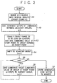
- Fig. 2 is a flow chart showing the operation of the apparatus for making the code book according to this embodiment.
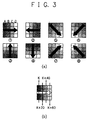
- Fig. 3 shows conceptional views for explaining the method of making the code book according to this embodiment.
- a set of pixel values which is formed from, e.g., a block of 4 pixels ⁇ 4 pixels is defined as one vector (to be referred to as a code vector hereinafter) in a code book, and a pattern whose pixel value (e.g., luminance value) in the block gradually changes from one of the edge portions (upper, lower, left, and right sides and four corner points) of the block is generated.
- a 4 ⁇ 4 pixel code vector is generated as an example.
- the present invention is not limited to this size.
- pattern 1 ⁇ is a pattern whose luminance value gradually increases, as A ⁇ B ⁇ C ⁇ D, from the left side to the right side of the block in units of vertical lines.
- the degree of change for example, the luminance value changes by 20 per pixel, as shown in Fig. 3(b). More specifically, letting K be the luminance value at the left end in the block, the luminance values at the second line, third line, and right end are K + 20, K + 40, and K + 60, respectively.
- 20 is defined as the maximum value of the degree of change in luminance value, and a pattern is generated while changing the degree to various values such as 10, 5, 2, and 1.
- the minimum and maximum values of possible values are given, and values appropriately dispersed therebetween are given. This generates variations in pattern whose luminance value gradually changes from the left side to the right side in the block, like pattern 1 ⁇ .
- the step width of the luminance value which gradually changes is not limited to the above-described examples.
- Pattern 2 ⁇ is a pattern whose luminance value gradually increases from the right side to the left side of the block in units of vertical lines
- pattern 3 ⁇ is a pattern whose luminance value gradually increases from the lower side to the upper side of the block in units of horizontal lines
- pattern 4 ⁇ is a pattern whose luminance value gradually increases from the upper side to the lower side of the block in units of horizontal lines.
- Pattern 5 ⁇ is a pattern whose luminance value gradually increases from the upper left corner to the lower right corner of the block in units of oblique lines
- pattern 6 ⁇ is a pattern whose luminance value gradually increases from the upper right corner to the lower left corner of the block in units of oblique lines
- pattern 7 ⁇ is a pattern whose luminance value gradually increases from the lower left corner to the upper right corner of the block in units of oblique lines
- pattern 8 ⁇ is a pattern whose luminance value gradually increases from the lower right corner to the upper left corner of the block in units of oblique lines.
- the luminance value gradually changes in seven steps.
- step S1 for example, a 4 ⁇ 4 pixel block is classified into several groups (the number of groups is N). For example, to generate the code vector of pattern 1 ⁇ shown in Fig. 3(a), the block is divided into four groups A to D in units of vertical lines.
- a start point in the block is set using a start point setting section 1 shown in Fig. 1.
- the start point setting section 1 can be constructed by an input device such as a keyboard or a mouse to cause the user to set an arbitrary start point.
- the apparatus itself may automatically set the start point in order sequentially to generate the eight patterns 1 ⁇ to 8 ⁇ shown in Fig. 3(a).
- a grouping section 2 performs grouping in accordance with the start point set by the start point setting section 1. For example, to generate pattern 1 ⁇ or 2 ⁇ shown in Fig. 3(a), grouping is performed in units of lines in the vertical direction, or to generate pattern 3 ⁇ or 4 ⁇ , grouping is performed in units of lines in the horizontal direction. To generate patterns 5 ⁇ to 8 ⁇ , grouping is performed in units of lines in the oblique directions.
- step S2 the increment (step) of the luminance value between adjacent groups is set using an increment setting section 3 shown in Fig. 1.
- the increment setting section 3 can also be constructed by an input device such as a keyboard or a mouse to cause the user to set an arbitrary increment, or the apparatus itself may automatically set a predetermined default value.
- processing of initializing a count value i for counting the number of processed groups to 0 is also performed.
- a start point luminance value setting section 4 shown in Fig. 1 sets the luminance value at the start point in the block.
- the equally divided value is given here, it need not always be the equally divided value as far as it falls within the range of 0 to (255 - (N - 1) ⁇ step).
- luminance values are given here by arithmetic operation, the user may arbitrarily input the luminance value at the start point within the above range by his/her discretion.
- a code book making section 5 When necessary pieces of information including the luminance value at the start point and the increment of luminance, are set, these pieces of information are supplied to a code book making section 5 shown in Fig. 1.
- the code book making section 5 executes processing from step S4 shown in Fig. 2, thereby generating one code vector. More specifically, as the luminance value as the start point in one code vector is set in processing until step S3, processing shifts to the group adjacent to the start point, and the count value i is incremented by one in step S4.
- step S5 it is determined whether the count value i is smaller than the value of group count N. If YES in step S5, an unprocessed group remains, and therefore the flow advances to step S6 to give a luminance value calculated by (the luminance value of the group at the start point + i ⁇ step) to the current group. The count value i is incremented by one, and the flow returns to step S5. This processing is repeated until no unprocessed group remains.
- step S7 When luminance values are given to all groups, the code vector of the pattern whose luminance value gradually increases from the start point to the end point in units of groups is generated. In this case, the flow advances to step S7 to store the code vector generated at this time in a code book data memory 6 shown in Fig. 1.
- one code vector is generated and stored in the code book data memory 6.
- code vectors having different luminance values are generated for the eight patterns 1 ⁇ to 8 ⁇ shown in Fig. 3(a).
- the set of the code vectors is a code book for a face image.
- the code book size is, e.g., 512.
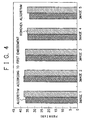
- Fig. 4 is a graph showing the PSNR (Peak Signal to Noise Ratio) characteristics of images which are obtained when vector quantization (VQ) is executed for five face images using the code book having a size of 512, which is made by the method of this embodiment, and then, the images are reconstructed using the same code book as that used for VQ.
- Fig. 4 also shows, as a reference, the PSNR characteristics of the images, which are obtained when the code book is individually optimized using the images by the Kohonen self-organizing map method, VQ processing is executed for each image using a corresponding code book, and then each image is reconstructed using the same code book as that used for VQ.
- PSNR Peak Signal to Noise Ratio
- the PSNR characteristic obtained in use of one code book made by the method of this embodiment is equivalent to that obtained in use of the five code books made by the Kohonen algorithm.
- even one code book can provide almost the same PSNR characteristic as that obtained when optimum code books are made by the Kohonen algorithm for the respective face images, so a greatly versatile code book can be made.
- a greatly versatile code book compatible to various face images with only one code book can be obtained. Additionally, in this embodiment, since each code vector is generated in accordance with a predetermined arithmetic operation pattern, which pattern is included in the optimized code book can easily be recognized.
- a pattern whose luminance value gradually increases from the start point to the end point in a block is generated. Conversely, a pattern whose luminance value gradually decreases may be generated.
- the maximum value of the degree of change is 20.
- 20 need not always be used, and an arbitrary value such as 40 or 10 is appropriately given.
- the code book size need not always be 512, either.
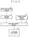
- Fig. 5 is a function block diagram showing the construction of the apparatus for making the code book according to this embodiment.
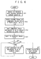
- Fig. 6 is a flow chart showing the operation of the apparatus for making the code book according to this embodiment.
- Fig. 7 shows conceptional views for explaining the method of making the code book for a landscape image according to this embodiment.
- a block is divisionally defined in, e.g., five regions.
- the dynamic range of luminance values of 256 levels is divisionally defined in five ranges.
- Fig. 7(a) shows a pattern whose luminance value gradually increases from the upper left corner to the lower right corner of the block.
- a block formed from 4 pixels ⁇ 4 pixels is obliquely segmented into five regions A to E.
- the dynamic range of luminance values from 0 to 255 is divisionally defined in five ranges corresponding to the five regions A to E, respectively.
- luminance values of 0 to 63 are defined for the region A
- luminance values of 63 to 95 are defined for the region B
- luminance values of 95 to 159 are defined for the region C
- luminance values 159 to 191 are defined for the region D
- luminance values of 191 to 255 are defined for the region E.
- a 4 ⁇ 4 pixel block is classified into several groups (the number of groups is N). For example, to generate the code vector of the pattern shown in Fig. 7(a), pixels in the block are divided into five groups A to E.
- a start point in the block is set using a start point setting section 11 shown in Fig. 5.
- a start point setting section 11 For example, to generate the pattern shown in Fig. 7(a), three pixels at the upper left corner in the block are set as a start point.
- the start point setting section 11 can be constructed by an input device such as a keyboard or a mouse to cause the user to set an arbitrary start point.
- the apparatus may automatically set the start point in order sequentially to generate patterns changing in four directions.
- a grouping section 12 performs grouping in accordance with the start point set by the start point setting section 11.
- step S12 the dynamic range of luminance values is divided into N parts (S 0 , S 1 ,..., S N-1 ) using a dynamic range dividing section 13 shown in Fig. 5 in accordance with the N regions after grouping.
- step S12 processing of initializing a count value i for counting the number of processed groups to 0 is also performed.
- these pieces of information are supplied to a code book making section 14 shown in Fig. 1.
- the code book making section 14 executes processing from step S13 shown in Fig. 6, thereby generating one code vector. More specifically, in step S13, for the group as the start point (group A in the example shown in Fig. 7), a luminance value belonging to the luminance level range S 0 corresponding to the group is set. In step S14, processing shifts to the group (group B in the example shown in Fig. 7) adjacent to the start point, and the count value i is incremented by one.
- step S15 it is determined whether the count value i is smaller than the value of group count N. If YES in step S15, an unprocessed group remains, and therefore the flow advances to step S16 to set, for the current group, a luminance value belonging to the luminance level range S 1 corresponding to the group. The count value i is incremented by one, and the flow returns to step S15. This processing is repeated until no unprocessed group remains.
- step S17 When luminance values are given to all groups, the code vector of the pattern whose luminance value gradually increases from the start point to the end point in units of groups is generated. In this case, the flow advances to step S17 to store the code vector generated at this time in a code book data memory 15 shown in Fig. 5.
- one code vector is generated and stored in the code book data memory 15.
- code vectors having different luminance values are generated as the code vectors of patterns which change in four directions.
- the set of the code vectors is a code book for a landscape image.
- a greatly versatile code book compatible to various landscape images with only one code book can be obtained. Additionally, in this embodiment, since each code vector is generated in accordance with a predetermined pattern, which pattern is included in the optimized code book can easily be recognized.
- a pattern whose luminance value gradually increases from the start point to the end point in a block is generated. Conversely, a pattern whose luminance value gradually decreases may be generated.
- the region in the block is divided into five regions.
- the code vector is divided into five regions only as an example, and the number of regions need not always be five.
- Fig. 8 is a function block diagram showing the construction of the apparatus for making the code book according to this embodiment.
- Fig. 9 is a flow chart showing the operation of the apparatus for making the code book according to this embodiment.
- Fig. 10 shows conceptional views for explaining the method of making the code book for a character image according to this embodiment.
- the vectors of four typical patterns as shown in Fig. 10 are generated as code vectors for a character image.
- the first patterns are patterns each obtained by appropriately embedding one of black patterns of seven types (patterns of minimum luminance values) of 1 ⁇ 1, 1 ⁇ 2, 1 ⁇ 3, 1 ⁇ 4, 2 ⁇ 2, 2 ⁇ 3, and 2 ⁇ 4 in a background white pattern (pattern of maximum luminance value) of 4 pixels ⁇ 4 pixels, as shown in Fig. 10(a).
- the second patterns are patterns each obtained by obliquely embedding black dots in a block, as shown in Fig. 10(b).
- the third pattern is a pattern obtained by embedding black dots in a cross, as shown in Fig. 10(c).
- the forth patterns are patterns each obtained by embedding a line of black dots while bending it midway, as shown in Fig. 10(d). In these patterns, a pixel value adjacent to a black dot is set to an intermediate value in accordance with whether the black dots linearly occupy the block.
- step S21 the ratio of pixels of black dots (minimum luminance value) in, e.g., a 4 ⁇ 4 pixel block is determined.
- the black dot ratio in the block is performed by a minimum luminance ratio setting section 21 shown in Fig. 8.
- the minimum luminance ratio setting section 21 can be constructed by an input device such as a keyboard or a mouse to cause the user to set an arbitrary ratio.
- the apparatus may automatically set the ratio in order sequentially to generate various patterns.
- step S22 black dots (minimum luminance value) are given to predetermined pixel positions in the block and white dots (maximum luminance value) are given to the other pixel positions using a maximum/minimum luminance value setting section 22 shown in Fig. 8 in accordance with the set black dot ratio.
- step S23 it is determined whether the black dots linearly occupy the block. If NO in step S23, the code vector generated in processing until step S22 is stored in a code book data memory 24 shown in Fig. 8.
- step S23 the flow advances to step S24 to change the luminance value of the pixel of a white dot adjacent to the pixel of a black dot to the halftone luminance value.
- the code vector generated in this way is stored in the code book data memory 24 shown in Fig. 8.
- one code vector is generated and stored in the code book data memory 24.
- code vectors of various patterns are generated.
- the set of the code vectors is a code book for a character image.
- a greatly versatile code book compatible to various character images with only one code book can be obtained. Additionally, in this embodiment, since each code vector is generated in accordance with a predetermined rule, which pattern is included in the made code book can easily be recognized.
- the code books made by the methods described in the first to third embodiments are combined into one code book having a size of 1,024.
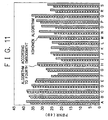
- Fig. 11 is a graph showing the PSNR characteristics of images, which are obtained when vector quantization (VQ) processing is performed for images A to S of 19 types, including face images, landscape images, and character images, using the code book having a size of 1,024 according to this embodiment and then, each image is reconstructed using the same code book as that used for VQ.
- Fig. 11 also shows, as a reference, the PSNR characteristics of the images, which are obtained when the code book is individually optimized using the images by the Kohonen self-organizing map method, VQ processing is executed for each image using a corresponding code book, and then each image is reconstructed using the same code book as that used for VQ.
- the PSNR characteristic obtained in use of one code book made by the method of this embodiment is equivalent to that obtained in use of the 19 code books made by the Kohonen algorithm.
- even one code book can provide almost the same PSNR characteristic as that obtained when optimum code books are made by the Kohonen algorithm for the respective images, and high-quality images can be reconstructed for various images including an image which monotonically changes or an image which abruptly changes, so a greatly versatile code book can be made.
- the size of the code book is set to 1,024.
- the size need not always be 1,024 and can be appropriately determined to, e.g., 128 or 512 in accordance with the application purpose.
- code books of three types are combined into one code book, code books of appropriate two types may be combined into one code book.
- a code vector of 4 pixels ⁇ 4 pixels is generated.
- the code vector need not always have 4 pixels ⁇ 4 pixels, and the target of vector quantization need not always be image data.
- the above-described code book making apparatus of this embodiment is constructed by a microcomputer system having a CPU, a ROM, and a RAM, and its operation is realized in accordance with an operation program stored in the ROM or RAM.
- a program for realizing the function of each function block of the code book making apparatus may be externally supplied to the computer through a recording medium to make the function block operate in accordance with the program.
- a recording medium which stores the program for example, a floppy disk, a hard disk, an optical disk, an optical magnetic disk, a CD-ROM, a CD-I, a CD-R, a CD-RW, a DVD, a zip, a magnetic tape, or a nonvolatile memory card can be used.
- the program is incorporated in the embodiments of the present invention not only when the functions of the above-described embodiments are realized when the computer executes the supplied program but also when the functions of the above-described embodiments are realized by the program cooperating with the OS (Operating System) or another application software running on the computer, or the functions of the above-described embodiments are realized when part or all of the processing of the supplied program is executed by the function expansion board or function expansion unit of the computer.
- OS Operating System
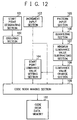
- Fig. 12 is a function block diagram showing the construction of an apparatus for making a code book according to the fifth embodiment.
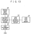
- Fig. 13 is a function block diagram showing the construction of a vector quantizing device for executing data compression using the made code book.
- Figs. 14 and 15 are illustrations showing examples of made code vectors (pattern images).
- a pattern which monotonically change in eight directions are generated, as shown in Fig. 14. More specifically, a pattern whose pixel value (e.g., luminance value) gradually changes from one of the edge portions (upper, lower, left, and right sides and four corner points) of a 4 ⁇ 4 pixel block is generated. In this case, a 4 ⁇ 4 pixel code vector is generated as an example. However, the present invention is not limited to this size.
- FIG. 14 shows a pattern whose luminance value gradually increases, as A ⁇ B ⁇ C ⁇ D, from the left side to the right side of the block in units of vertical lines, (b) shows a pattern whose luminance value gradually increases from the right side to the left side of the block in units of vertical lines, (c) shows a pattern whose luminance value gradually increases from the lower side to the upper side of the block in units of horizontal lines, and (d) shows a pattern whose luminance value gradually increases from the upper side to the lower side of the block in units of horizontal lines.
- (e) shows a pattern whose luminance value gradually increases from the upper left corner to the lower right corner of the block in units of oblique lines
- (f) shows a pattern whose luminance value gradually increases from the upper right corner to the lower left corner of the block in units of oblique lines
- (g) shows a pattern whose luminance value gradually increases from the lower left corner to the upper right corner of the block in units of oblique lines
- (h) shows a pattern whose luminance value gradually increases from the lower right corner to the upper left corner of the block in units of oblique lines.
- a 4 ⁇ 4 pixel block is classified into several groups.
- the block is divided into four groups A to D in units of vertical lines.
- the user designates a start point in the block using a start point designating section 101 shown in Fig. 12.
- a start point designating section 101 shown in Fig. 12.
- the four pixels (group A) at the left side in the block are designated as a start point.
- the start point designating section 101 is constructed by an input device such as a keyboard or a mouse.
- a grouping section 102 performs grouping in accordance with the start point designated by the start point designating section 101. For example, to generate the pattern shown in Fig. 14(a) or 14(b) as a basic pattern, grouping is performed in units of lines in the vertical direction, or to generate the pattern shown in Fig. 14(c) or 14(d) as a basic pattern, grouping is performed in units of lines in the horizontal direction. To generate the patterns shown in Figs. 14(e) to 14(h) as basic patterns, grouping is performed in units of lines in the oblique directions.
- step S102 the user inputs at least one increment h of the luminance value at the end point when viewed from the start point in the block using an increment input section 103 shown in Fig. 12.
- the increment input section 103 is also constructed by an input device such as a keyboard or mouse. Instead of inputting the increment h by the user, the apparatus may set a predetermined default value.
- a start point luminance value setting section 104 shown in Fig. 12 sets the luminance value at the start point in the block.
- the range of 0 to (intermediate value of the possible range of luminance values - increment h) is equally divided into n parts, and each equally divided value is set as the luminance value at the start point.
- the equally divided value is given here, it need not always be the equally divided value as far as it falls within the range of 0 to (intermediate value of the possible range of luminance values - increment h).
- luminance values are given here by arithmetic operation, the user may arbitrarily input the luminance value at the start point within the above range by his/her discretion.
- a code book making section 109 shown in Fig. 12 executes arithmetic operation of, e.g., linear interpolation on the basis of the luminance value at the start point and the increment h of luminance value, thereby calculating the luminance value of each group.
- a code book making section 109 shown in Fig. 12 executes arithmetic operation of, e.g., linear interpolation on the basis of the luminance value at the start point and the increment h of luminance value, thereby calculating the luminance value of each group.
- the code of the basic solid pattern generated here is a relatively dark image whose luminance value as a whole is smaller than the intermediate value.
- step S102 at least one increment h is given, and in step S103, luminance values at the start point are given on the basis of the value of each increment h.
- codes are generated for the basic pattern shown in Fig. 14(a) on the basis of different luminance values.
- One increment h and one luminance value at the start point may be given to generate only one basic pattern.
- the codes (code vectors) generated in the above way are stored in a code book data memory 110 as a basic solid pattern code book in step S105.
- a pattern whose luminance value gradually increases from the start point to the end point in a block is generated.
- a pattern whose luminance value gradually decreases may be generated.
- codes of basic patterns related to edges for example, patterns of 12 types as shown in Fig. 15 are generated as patterns whose luminance values abruptly change. In all edge patterns generated here, the edge portion is present on at least one of the four pixels constituting the left side in the block.
- the basic patterns of 12 types are shown, the number of types is not limited to 12.
- step S111 several reference patterns which should be employed as edge patterns are input using a pattern input section 105 shown in Fig. 12.
- the luminance structure is input as the luminance structure of an edge pattern.
- a quantizing section 106 quantizes the luminance value of each pixel in the blocks constituting the patterns, thereby expressing the luminance values in the blocks using only predetermined values.
- a minimum luminance value subtracting section 107 subtracts the minimum luminance value in each block from the luminance values of all pixels in the block.
- the luminance value of each pixel in the block is expressed by only an increment value (difference value) with respect to the minimum luminance value.
- a luminance value change section 108 also generates patterns in which the luminance value of each pixel in the block is changed to make variations of the edge pattern to be registered.
- the luminance values of all pixels in the block of the pattern generated by the minimum luminance value subtracting section 107 are equally divided into m parts, and each equally divided value is set as the luminance value of each pixel, thereby increasing the number of patterns to m.
- the difference between the minimum luminance value (it is set to 0 in step S113) and the maximum luminance value in the block, i.e., an increment h' is known.
- the start point luminance value setting section 104 shown in Fig. 12 sets the luminance value (minimum luminance value) at the start point in the block.
- the luminance value at the start point for example, the range of 0 to (maximum value of the possible range of luminance values - increment h') is equally divided into k parts, and each equally divided value is set as the luminance value at the start point. In this case as well, the value need not always be an equally divided value, as in step S103 shown in Fig. 16.
- the user may arbitrarily input a luminance value within the above range by his/her discretion.
- the code book making section 109 shown in Fig. 12 calculates the luminance value of each pixel in the block on the basis of the luminance value at the start point and the luminance value of each pixel of the patterns generated in step S114.
- codes of edge patterns whose luminance values abruptly change are generated.
- the codes (code vectors) generated in the above way are stored in the code book data memory 110 as a basic edge pattern code book in step S117.
- Fig. 13 is a function block diagram showing the schematic construction of a vector quantizing device according to this embodiment.
- Fig. 18 is a flow chart showing the operation of this vector quantizing device.
- step S121 shown in Fig. 18 an original image input section 121 inputs arbitrary image data as a compression target.
- a code book arithmetic operation section 122 reads out the basic pattern code books stored in the code book data memory 110. In this case, all basic patterns of the solid patterns and edge patterns are read.
- step S123 the code book arithmetic operation section 122 that has read the basic patterns rotates each read basic pattern through 90° four times, thereby generating the codes of different patterns from the basic pattern.
- the patterns shown in Figs. 14(a) and 14(e) are registered as the basic patterns of solid patterns
- the patterns shown in Figs. 14(b) to 14(d) and Figs. 14(f) to 14(h) are generated by this processing.
- the edge patterns as well, the basic patterns of 12 types shown in Fig. 15 are rotated to generate different patterns from these basic patterns.
- the number of patterns of codes increases to four times.
- step S124 the code book arithmetic operation section 122 also executes, for each pattern obtained in step S123, processing of inverting the white and black portions (processing of folding back the luminance value with respect to the intermediate value), thereby further generating codes of different patterns.
- the patterns obtained by rotation processing will not be the same.
- a basic solid pattern generated in advance is a relatively dark pattern whose luminance values of all pixels are smaller than the intermediate value
- the patterns obtained by white/black inversion processing are relatively bright patterns whose luminance values of all pixels are larger than the intermediate value.
- the patterns obtained by rotation processing will not be the same.
- the pattern is input assuming whether the same patterns are to be generated by rotation processing or white/black inversion processing.
- this operation is not always easy.
- Such disadvantage can be avoided by, e.g., providing, in the code book making apparatus shown in Fig. 12, an arithmetic operation section for executing rotation processing or white/black inversion processing, and when comparison between the arithmetic operation result with the original data reveals the same patterns, outputting an error.
- step S125 shown in Fig. 18 arithmetic operation of vector quantization (VQ) is executed on the basis of the original image data input in step S121 and the code data generated by the code book arithmetic operation section 122. More specifically, first, using the original image data and code data, a similarity arithmetic operation section 123 shown in Fig. 13 calculates the similarity therebetween in units of blocks.
- VQ vector quantization
- the similarity is a numerical value which is obtained by inputting, to a certain function, vector data constituted by pixel values in a block extracted from original image data and vector data constituted by pixel values in the block of code vector and represents the degree of similarity therebetween.
- a representative example of such a function is a function for obtaining the Manhattan distance (absolute difference value distance) or Euclidean distance between two input vector data.
- a code determining section 124 determines, in units of blocks, a code vector having the largest similarity (the smallest Manhattan distance or Euclidean distance) for the code vectors generated by the code book arithmetic operation section 122.
- a code corresponding to the determined code vector is applied to the block, thereby outputting compressed data.
- the codes of solid patterns and the codes of edge patterns are generated in advance.
- basic patterns are standardized and generated according to a predetermined processing procedure.
- codes of different variations are generated by rotation processing or white/black inversion processing. For this reason, the code of a pattern closer to the original image can be applied, and the quality of the reconstructed image can be further improved. In this case, these generated codes need not be stored in the code book data memory 110 in advance either, the capacity of the code book data memory 110 can be suppressed.
- the basic pattern code books are made in advance and stored in the code book data memory 110.
- pieces of information e.g., information including the position of the start point, start point luminance value, the increment from the start point to the end point
- the codes of various patterns, including the basic patterns may be generated in actually executing vector quantization.
- the memory capacity can be made smaller.
- rotation processing and white/black inversion processing are performed in executing vector quantization.
- these processes may be performed in advance before execution of vector quantization and stored in the code book data memory 110.
- the capacity of the code book data memory 110 becomes large, the advantage that a versatile code book can be provided is obtained.
- the processing speed becomes high.
- steps S113 to S116 shown in Fig. 17 are also done to increase the number of patterns of usable code vectors. Hence, as described above, in order to suppress the capacity of the code book data memory 110 as small as possible, these steps may be omitted, and only processing of standardizing the pixel values may be performed in step S112.
- processing as in the above embodiment is preferably executed not only to reduce the capacity of the code book data memory 110 as small as possible but also to improve the quality of the reconstructed image as much as possible.
- both rotation processing and white/black inversion processing are performed. However, only one of them may be executed.
- a code vector is rotated or inverted by the code book arithmetic operation section 122.
- the original image may be rotated or inverted to calculate the similarity without processing the code vector.
- a pattern which is relatively dark as a whole is generated. Conversely, a relatively bright pattern may be generated.
- Each of the function blocks shown in Figs. 12 and 13 is constructed by, e.g., a microcomputer system comprising a CPU or an MPU, a ROM, and a RAM such that its operation can be realized in accordance with an operation program stored in the ROM or RAM, or constructed by hardware.
- a microcomputer system comprising a CPU or an MPU, a ROM, and a RAM such that its operation can be realized in accordance with an operation program stored in the ROM or RAM, or constructed by hardware.
- Figs. 12 and 13 are independently illustrated, these constructions may be combined to form one vector quantizing device.
- an operation program code for realizing the function of each function block may be supplied from an external recording medium to the computer, and each function block may be operated in accordance with the program.
- a recording medium which stores the program for example, a floppy disk, a hard disk, an optical disk, an optical magnetic disk, a CD-ROM, a CD-I, a CD-R, a CD-RW, a DVD, a zip, a magnetic tape, or a nonvolatile memory card can be used as a recording medium which stores the program.
- a recording medium which stores the program for example, a floppy disk, a hard disk, an optical disk, an optical magnetic disk, a CD-ROM, a CD-I, a CD-R, a CD-RW, a DVD, a zip, a magnetic tape, or a nonvolatile memory card can be used.
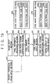
- Fig. 19 is a block diagram showing a construction of a system for data compression/decompression according to the sixth embodiment.
- Fig. 20 is an illustration for explaining the operation principle of the operation according to this embodiment. The principle will be described first with reference to Fig. 20.
- blocks for example, one block has 4 ⁇ 4 pixels
- blocks extracted from an original image in executing vector quantization are classified into blocks (to be referred to as low-frequency patterns or solid patterns hereinafter) each having pixel values gradually changing in a predetermined direction in the block and blocks (to be referred to as high-frequency patterns or edge patterns hereinafter) each having pixel values abruptly changing in the block.
- VQ processing is independently performed for the blocks of solid patterns and edge patterns using a low-frequency code book and high-frequency code book, which are prepared in advance for the respective patterns, and results obtained for the respective patterns are combined to obtain compressed data.
- VQ Vector quantization
- Fig. 19 shows a construction for realizing such operation.
- an image input section 201 inputs image data as a compression target.
- This image input section 201 has a function of segmenting the entire input image into blocks each formed from, e.g., 4 ⁇ 4 pixels and outputting an image in units of blocks.
- the image data as a compression target can be either a still image or a moving picture.
- the image data can be either a monochromatic image or a color image.
- a pixel arithmetic operation section 202 executes arithmetic operation necessary to determine whether an input block image corresponds to a solid pattern or edge pattern. For example, the minimum luminance value and maximum luminance value are detected from pixels in the block, and the difference therebetween is calculated. When this difference is small, the image corresponds to a solid pattern whose luminance value gradually changes. When the difference is large, the image corresponds to an edge pattern whose luminance value abruptly changes.
- a search threshold value input section 203 inputs a threshold value necessary for pattern determination based on the difference between the minimum luminance value and the maximum luminance value in the block, which is calculated by the pixel arithmetic operation section 202.
- a code-book-scheme compressing section 204 determines whether the block is a solid pattern or edge pattern on the basis of the arithmetic operation result received from the pixel arithmetic operation section 202 and the threshold value received from the search threshold value input section 203, and executes vector quantization processing using an appropriate code book according to the pattern.
- the block is a solid pattern
- vector quantization is executed using a solid pattern code book 205a stored in a code book storage section 205 in advance.
- the block is an edge pattern
- vector quantization is executed using an edge pattern code book 205b stored in the code book storage section 205 in advance.
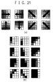
- the code book storage section 205 stores in advance as code vectors pixel patterns each having the same size (4 ⁇ 4 pixel block) as that of the block extracted from the original image.
- a set of patterns each having a pixel value (e.g., luminance value) gradually changing from as the start point one of the edge portions (upper, lower, left, and right sides and four corner points) of a block formed from 4 ⁇ 4 pixels is registered.
- a number of solid patterns are actually registered with variations in luminance value at the start point or degree of change in luminance.
- edge pattern code book 205b code vectors of patterns each having a luminance value abruptly changing are registered, as shown in Fig. 21(b). Although only 12 patterns are illustrated, a number of edge patterns are actually registered with variations or including patterns other than those illustrated here.
- a code number output section 206 outputs a code number string obtained as a result of vector quantization executed by the code-book-scheme compressing section 204 in units of blocks.
- the code vectors constituting the solid pattern code book 205a and edge pattern code book 205b are assigned a series of code numbers (addresses of a storage device or the like), and a code number string corresponding to code vectors searched as code vectors having large similarities is output in units of blocks.
- the construction on the compressing side has been described above.
- a code number input section 207 receives the code number string of blocks output from the code number output section 206 on the compressing side.
- the code number output section 206 and code number input section 207 can be connected through a communication path such as a network such that a code number is transferred through this network.
- the code number string output from the code number output section 206 may be temporarily stored in a storage medium such as a floppy disk and input to the decompressing side through the storage medium.
- a code-book-scheme decompressing section 208 executes processing of reading out, from a code book storage section 209, the pattern images of code vectors corresponding to the code number sequence received from the code number input section 207 and embedding the pattern images at corresponding block positions, thereby generating a reconstructed image.
- a corresponding code vector is read out from a solid pattern code book 209a.
- a corresponding code vector is read out from an edge pattern code book 209b.
- the code book storage section 209 stores in advance, as code vectors, pixel patterns each having the same size (4 ⁇ 4 pixel block) as the block extracted from the original image.
- the code books on the compressing side can be transmitted and stored before decompression processing. Alternatively, identical code books may be stored from the beginning.
- the reconstructed image generated by the code-book-scheme decompressing section 208 is supplied to an image display device or a storage device 210 and displayed as an image or stored as image data.
- the construction on the decompressing side has been described above.
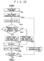
- Fig. 22 shows the operation on the compressing side. Referring to Fig. 22, first in step S201, processing processing is executed. In this case, processing of clearing the block counter for counting processed blocks is executed.
- step S202 a threshold value T H for search is given, and then in step S203, one image block is input.
- step S204 for the input image block, the difference between the maximum luminance value and the minimum luminance value in the block is calculated, and it is determined whether the calculation result is larger than the search threshold value T H .
- step S205 execute vector quantization processing using the edge pattern code book 205b and search for the code vector of an edge pattern most similar to the input image block.
- step S206 execute vector quantization processing using the solid pattern code book 205a and search for the code vector of a solid pattern most similar to the input image block.
- step S205 When vector quantization processing is ended in step S205 or S206, the flow advances to step S207, the image of the input block is replaced with a code number corresponding to the search code vector and encoded. After that, in step S208, the replaced code number is output.
- step S209 determines whether the above-described processing is ended for all blocks in the image. If NO in step S209, the value of the block counter is incremented by one in step S210, and the flow returns to step S203 to repeat the above processing.
- step S208 can be replaced with that in step S209 to output the code number string of one image together.
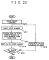
- Fig. 23 shows the operation on the decompressing side. Referring to Fig. 23, first in step S211, processing processing is executed. In this case, processing of clearing the block counter for counting processed blocks is executed. In step S212, a code number specified on the compressing side is input.
- step S213 on the basis of the input code number, the pattern image of a code vector corresponding to the code number is searched from the solid pattern code book 209a or edge pattern code book 209b.
- the pattern image is read out and embedded at a corresponding block position (more specifically, the pattern image is stored at a predetermined position of a reconstructed image buffer).
- step S215 After the reconstructed image generated is display on a display or stored in a storage medium in step S214, the flow advances to step S215 to determine whether the above-described processing is ended for all blocks in the image. If NO in step S215, the value of the block counter is incremented by one in step S216, and then the flow returns to step S212 to repeat the above processing.
- step S214 can be replaced with that in step S215 to execute image display or storage processing after one reconstructed image is entirely generated.
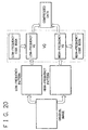
- the solid pattern section and edge pattern section are provided in one code book.
- two code books i.e., the code book for solid patterns and that for edge patterns may be separately prepared.
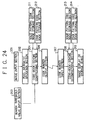
- solid pattern code book storage sections 211 and 213 for storing code books for solid patterns and edge pattern code book storage sections 212 and 214 for storing code books for edge patterns are separately prepared.
- a solid pattern and an edge pattern may be assigned a single code number.
- flag information is transmitted together with a code number.
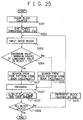
- step S221 when the difference value calculated between the maximum luminance value and the minimum luminance value in a block is larger than the search threshold value T H , vector quantization processing is executed using the code book in the edge pattern code book storage section 212, and the flag is set to "1".
- step S222 when the calculated difference value is not larger than the search threshold value T H , vector quantization processing is executed using the code book in the solid pattern code book storage section 211, and the flag is set to "0".
- step S223 the flag information set in the above manner is output in addition to the replaced code number.
- step S212 shown in Fig. 23 is replaced with the process in step S224 and the processes in step S213 is replaced with the processes in step S225, S226, and S227.
- step S224 the above flag information is input in addition to the code number specified on the compressing side.
- step S225 it is determined whether the input flag is "1". If YES in step S225, the flow advances to step S226. If NO in step S225, the flow advances to step S227.
- step S2266 on the basis of the input code number, the pattern image of a code vector corresponding to the code number is read out from the edge pattern code book storage section 214 and embedded at a corresponding block position.
- step S227 on the basis of the input code number, the pattern image of a code vector corresponding to the code number is read out from solid pattern code book storage section 213 and embedded at a corresponding block position.
- the luminance distribution in each block extracted from the original image is detected, and it is determined whether the block is a solid pattern or edge pattern of the image.
- a code vector having large similarity is selected from the solid pattern section in the code book or an independently prepared solid pattern code book.
- a code vector having large similarity is selected from the edge pattern section in the code book or an independently prepared edge pattern code book.
- an optimum pattern image can be selected for a solid pattern from a code book corresponding to solid patterns, and an optimum pattern image can be selected for an edge pattern from a code book corresponding to edge patterns.
- the direction of change in luminance value of each pixel in a block acts as an important factor.
- the direction of luminance change can be predicted from the pixel values at the four corners in the block.
- a block shown in Fig. 27 is the block of a solid pattern in which the luminance value gradually increases from the upper right pixel to the lower left pixel in the block, or the luminance value gradually decreases from the lower left pixel to the upper right pixel.
- the direction of change in luminance value in the block can be known.
- arithmetic operation is performed for a solid pattern using only pieces of information on the pixels (four dimensions) at the four corners instead of arithmetic operation using pieces of information on all pixels (16 dimensions) in the block.
- the construction for implementing a system for data compression/decompression according to the seventh embodiment is the same as that shown in Fig. 19 or 24.
- the contents of vector quantization processing executed by a code-book-scheme compressing section 204 are different from those of the sixth embodiment.
- the flow chart showing the operation is also almost the same as in the sixth embodiment except the contents of search processing in step S206 shown in Fig. 22 and in step S222 shown in Fig. 25.
- the Manhattan distance or Euclidean distance is calculated using all the 16 pixels in a block, thereby obtaining similarity between two vectors.
- similarity such as the Manhattan distance is calculated using only pixels at the four corners, and simultaneously, the direction of luminance change in the block is detected.
- a code vector having large similarity to the input vector of the original image and having the same direction of luminance change as that of the input vector is selected from a code book.
- each code vector in the code book may be constituted by only the four-dimensional information corresponding to the pixels at the four corners instead of constituting the code vector by 16-dimensional information as in the sixth embodiment. This reduces the storage capacity of the code book storage section.
- code vectors of a larger number of types can be registered without increasing the storage capacity, and the quality of a reconstructed image can be further improved.
- each code vector is constituted using only the four-dimensional information
- each code vector is constituted using the 16-dimensional information
- each code vector may be constituted by only the four-dimensional information and pieces of information on pixels except the four corners may be generated from the pieces of information on the pixels at the four corners by arithmetic operation, e.g., linear interpolation.
- arithmetic operation section for calculating linear interpolation or the like is arranged on the output side of a code-book-scheme decompressing section 208 shown in Fig. 19.
- the block size is set to 4 ⁇ 4 pixels.
- the present invention is not limited to this.
- the present invention is not limited to this method as far as the two patterns can be discriminated.
- blocks may be classified into different patterns using other information (e.g., color information), and vector quantization may be independently executed for the blocks.
- the classified patterns are not limited to the above-described two types, and blocks may be classified into patterns of a larger number of types.
- Each of the function blocks shown in Fig. 19 or 24 can be constructed by either hardware or a microcomputer system comprising a CPU or an MPU, a ROM, and a RAM in this embodiment such that its operation is realized in accordance with an operation program stored in the ROM or RAM.
- the present invention also incorporates a case wherein a software program for realizing the functions to realize the function of each function block is supplied to the RAM, and each function block is made to operate in accordance with the program.
- the software program itself constitutes the functions of the above-described embodiments, and the program itself, and the means for supplying the program to the computer, and for example, a recording medium which stores the program constitutes the present invention.
- a recording medium which stores the program for example, not only the ROM or RAM but also a floppy disk, a hard disk, an optical disk, an optical magnetic disk, a CD-ROM, a CD-I, a CD-R, a CD-RW, a DVD, a zip, a magnetic tape, or a nonvolatile memory card can be used.
- the program is incorporated in the embodiments of the present invention not only when the functions of the above-described embodiments are realized when the computer executes the supplied program but also when the functions of the above-described embodiments are realized by the program cooperating with the OS (Operating System) or another application software running on the computer.
- OS Operating System
- the present invention also incorporates a case wherein the functions of the above-described embodiments are realized when the supplied program is stored in a memory provided in the function expansion board of the computer or the function expansion unit connected to the computer, and the CPU provided in the function expansion board or function expansion unit executes part or all of actual processing on the basis of instructions of the program.
- a greatly versatile code book capable of coping with various data including data which monotonically varies or data which abruptly varies can be realized without increasing the memory capacity for storing it.
- a greatly versatile system for data compression/decompression which can reconstruct high-quality images for various images even at a high compression ratio can be implemented.
- a pattern is discriminated on the basis of information in a block extracted from a compression target, and vector quantization is executed using an appropriate code book prepared for each pattern.
Landscapes
- Engineering & Computer Science (AREA)
- Multimedia (AREA)
- Theoretical Computer Science (AREA)
- Signal Processing (AREA)
- Physics & Mathematics (AREA)
- General Physics & Mathematics (AREA)
- Compression, Expansion, Code Conversion, And Decoders (AREA)
- Compression Or Coding Systems Of Tv Signals (AREA)
- Compression Of Band Width Or Redundancy In Fax (AREA)
Applications Claiming Priority (9)
| Application Number | Priority Date | Filing Date | Title |
|---|---|---|---|
| JP12428398 | 1998-04-17 | ||
| JP12428398 | 1998-04-17 | ||
| JP18951698A JP3527415B2 (ja) | 1998-07-03 | 1998-07-03 | ベクトル量子化で用いるコードブックの作成装置および方法、ベクトル量子化方法、記録媒体 |
| JP18951698 | 1998-07-03 | ||
| JP20836598A JP2000040966A (ja) | 1998-07-23 | 1998-07-23 | データ圧縮装置および方法、データ伸長装置および方法、データ圧縮伸長システム、記録媒体 |
| JP20836598 | 1998-07-23 | ||
| JP30980898 | 1998-10-30 | ||
| JP30980898A JP3998348B2 (ja) | 1998-04-17 | 1998-10-30 | ベクトル量子化で用いるコードブックの作成方法および装置、記録媒体 |
| PCT/JP1999/002050 WO1999055007A1 (en) | 1998-04-17 | 1999-04-19 | Method and apparatus for making code book, vector quantizing device, device and method for data compression, device and method for data decompression, system for data compression/decompression |
Publications (1)
| Publication Number | Publication Date |
|---|---|
| EP1087533A1 true EP1087533A1 (de) | 2001-03-28 |
Family
ID=27471020
Family Applications (1)
| Application Number | Title | Priority Date | Filing Date |
|---|---|---|---|
| EP99913695A Withdrawn EP1087533A1 (de) | 1998-04-17 | 1999-04-19 | Verfahren und vorrichtung zur herstellung eines codebuches, einer vektorquantisierungsvorrichtung, einer vorrichtung und eines verfahrens zur datenkomprimierung, einer vorrichtung und eines verfahrens zur datendekomprimierung, eines systems für datenkomprimierung/dekomprimierung |
Country Status (2)
| Country | Link |
|---|---|
| EP (1) | EP1087533A1 (de) |
| WO (1) | WO1999055007A1 (de) |
Cited By (8)
| Publication number | Priority date | Publication date | Assignee | Title |
|---|---|---|---|---|
| US6996257B2 (en) | 2000-12-19 | 2006-02-07 | Matsushita Electric Industrial Co., Ltd. | Method for lighting- and view -angle-invariant face description with first- and second-order eigenfeatures |
| US8438558B1 (en) | 2009-03-27 | 2013-05-07 | Google Inc. | System and method of updating programs and data |
| US9253505B2 (en) | 2009-04-08 | 2016-02-02 | Newrow, Inc. | System and method for image compression |
| US10244256B2 (en) | 2014-10-08 | 2019-03-26 | Sharp Kabushiki Kaisha | Image decoding device |
| US10872186B2 (en) | 2017-01-04 | 2020-12-22 | Stmicroelectronics S.R.L. | Tool to create a reconfigurable interconnect framework |
| US11227086B2 (en) | 2017-01-04 | 2022-01-18 | Stmicroelectronics S.R.L. | Reconfigurable interconnect |
| US11531873B2 (en) | 2020-06-23 | 2022-12-20 | Stmicroelectronics S.R.L. | Convolution acceleration with embedded vector decompression |
| US11593609B2 (en) | 2020-02-18 | 2023-02-28 | Stmicroelectronics S.R.L. | Vector quantization decoding hardware unit for real-time dynamic decompression for parameters of neural networks |
Families Citing this family (1)
| Publication number | Priority date | Publication date | Assignee | Title |
|---|---|---|---|---|
| KR100926366B1 (ko) * | 2008-07-30 | 2009-11-10 | 주식회사 코아로직 | 코드북 결정 방법, 오디오 신호의 부호화 방법 및 장치 |
Family Cites Families (9)
| Publication number | Priority date | Publication date | Assignee | Title |
|---|---|---|---|---|
| JPS6232785A (ja) * | 1985-08-05 | 1987-02-12 | Fujitsu Ltd | 適応形ベクトル量子化方式 |
| JP2872241B2 (ja) * | 1987-09-24 | 1999-03-17 | キヤノン株式会社 | 画像符号化方法 |
| US5136374A (en) * | 1990-04-03 | 1992-08-04 | At&T Bell Laboratories | Geometric vector quantization |
| JPH04139958A (ja) * | 1990-10-01 | 1992-05-13 | Tokyo Electric Co Ltd | 画像符号化方式 |
| JPH04302376A (ja) * | 1991-03-29 | 1992-10-26 | Tokyo Electric Co Ltd | ベクトル量子化方式 |
| JP2679769B2 (ja) * | 1992-11-16 | 1997-11-19 | 富士ゼロックス株式会社 | 画像信号の符号化装置 |
| JP3640318B2 (ja) * | 1995-09-01 | 2005-04-20 | インターナショナル・ビジネス・マシーンズ・コーポレーション | ディジタル画像の符号化方法及びシステム |
| JPH08317385A (ja) * | 1995-05-18 | 1996-11-29 | Matsushita Electric Ind Co Ltd | 画像符号化装置および復号化装置 |
| JPH09130259A (ja) * | 1995-10-31 | 1997-05-16 | Casio Comput Co Ltd | ベクトル量子化符号化方式、及びベクトル復号方式 |
-
1999
- 1999-04-19 WO PCT/JP1999/002050 patent/WO1999055007A1/ja not_active Application Discontinuation
- 1999-04-19 EP EP99913695A patent/EP1087533A1/de not_active Withdrawn
Non-Patent Citations (1)
| Title |
|---|
| See references of WO9955007A1 * |
Cited By (12)
| Publication number | Priority date | Publication date | Assignee | Title |
|---|---|---|---|---|
| US6996257B2 (en) | 2000-12-19 | 2006-02-07 | Matsushita Electric Industrial Co., Ltd. | Method for lighting- and view -angle-invariant face description with first- and second-order eigenfeatures |
| US8438558B1 (en) | 2009-03-27 | 2013-05-07 | Google Inc. | System and method of updating programs and data |
| US9253505B2 (en) | 2009-04-08 | 2016-02-02 | Newrow, Inc. | System and method for image compression |
| US10244256B2 (en) | 2014-10-08 | 2019-03-26 | Sharp Kabushiki Kaisha | Image decoding device |
| US10872186B2 (en) | 2017-01-04 | 2020-12-22 | Stmicroelectronics S.R.L. | Tool to create a reconfigurable interconnect framework |
| US11227086B2 (en) | 2017-01-04 | 2022-01-18 | Stmicroelectronics S.R.L. | Reconfigurable interconnect |
| US11562115B2 (en) | 2017-01-04 | 2023-01-24 | Stmicroelectronics S.R.L. | Configurable accelerator framework including a stream switch having a plurality of unidirectional stream links |
| US11675943B2 (en) | 2017-01-04 | 2023-06-13 | Stmicroelectronics S.R.L. | Tool to create a reconfigurable interconnect framework |
| US11593609B2 (en) | 2020-02-18 | 2023-02-28 | Stmicroelectronics S.R.L. | Vector quantization decoding hardware unit for real-time dynamic decompression for parameters of neural networks |
| US11880759B2 (en) | 2020-02-18 | 2024-01-23 | Stmicroelectronics S.R.L. | Vector quantization decoding hardware unit for real-time dynamic decompression for parameters of neural networks |
| US11531873B2 (en) | 2020-06-23 | 2022-12-20 | Stmicroelectronics S.R.L. | Convolution acceleration with embedded vector decompression |
| US11836608B2 (en) | 2020-06-23 | 2023-12-05 | Stmicroelectronics S.R.L. | Convolution acceleration with embedded vector decompression |
Also Published As
| Publication number | Publication date |
|---|---|
| WO1999055007A1 (en) | 1999-10-28 |
Similar Documents
| Publication | Publication Date | Title |
|---|---|---|
| JP3017380B2 (ja) | データ圧縮方法及び装置並びにデータ伸長方法及び装置 | |
| US6556711B2 (en) | Image processing apparatus and method | |
| JP3373008B2 (ja) | 画像像域分離装置 | |
| US7221483B2 (en) | Image encoding method and apparatus, image decoding method and apparatus, image processing apparatus, image formation apparatus, and computer-executable programs | |
| JP3980332B2 (ja) | 画像圧縮方法及び画像圧縮システム | |
| US20020064310A1 (en) | Image matching | |
| JP2003346166A (ja) | マスクを利用して文書画像の圧縮を容易にするシステムおよび方法 | |
| JPH11316843A (ja) | デジタル画像の適応量子化のための画像ブロックのタイプ判定方法 | |
| JPH0799581A (ja) | 画像処理装置 | |
| JP4662696B2 (ja) | 画像信号を一組の画像プレーンに分離するための方法及びシステム | |
| US6909804B2 (en) | Image compression usable with animated images | |
| EP1087533A1 (de) | Verfahren und vorrichtung zur herstellung eines codebuches, einer vektorquantisierungsvorrichtung, einer vorrichtung und eines verfahrens zur datenkomprimierung, einer vorrichtung und eines verfahrens zur datendekomprimierung, eines systems für datenkomprimierung/dekomprimierung | |
| US5613015A (en) | Image signal analyzing system and coding system | |
| US20050281463A1 (en) | Method and apparatus for processing binary image | |
| Kopylov et al. | Compression of map images by multilayer context tree modeling | |
| US20070098271A1 (en) | Apparatus and method for image coding | |
| US7342517B2 (en) | Apparatus and method of binary image compression | |
| JP2679769B2 (ja) | 画像信号の符号化装置 | |
| JP2002199401A (ja) | 画像符号化装置、画像復号化装置、電子カメラ、および記録媒体 | |
| JP3977291B2 (ja) | 画像再生方法及び画像処理装置 | |
| JP3647071B2 (ja) | 画像処理装置およびその方法 | |
| JP2004312693A (ja) | 画像符号化装置及び画像符号化方法 | |
| EP1079635A1 (de) | Datenkompressionsvorrichtung und -verfahrem, datenerweiterungsvorrichtung und-verfahren, datenkompressions/erweiterungssystem und-verfahren, verfahren zur erstellung eines code-buchs und vektorquantisierungsvorrichtung und -verfahren | |
| JP2000201078A (ja) | デ―タ圧縮装置および方法、デ―タ伸長装置および方法、デ―タ圧縮伸長システムおよび方法、コ―ドブックの作成方法、記録媒体 | |
| WO2006022741A1 (en) | Image compression usable with animated images |
Legal Events
| Date | Code | Title | Description |
|---|---|---|---|
| PUAI | Public reference made under article 153(3) epc to a published international application that has entered the european phase |
Free format text: ORIGINAL CODE: 0009012 |
|
| 17P | Request for examination filed |
Effective date: 20001116 |
|
| AK | Designated contracting states |
Kind code of ref document: A1 Designated state(s): DE FR GB NL SE |
|
| RAP1 | Party data changed (applicant data changed or rights of an application transferred) |
Owner name: I & F CORPORATION Owner name: ULTRA CLEAN TECHNOLOGY CORPORATION Owner name: OHMI, TADAHIRO |
|
| RIN1 | Information on inventor provided before grant (corrected) |
Inventor name: NOZAWA, TOSHIYUKI Inventor name: YONEZAWA, TAKEMI Inventor name: MORIMOTO, TATSUO Inventor name: KONDA, MASAHIRO Inventor name: IMAI, MAKOTO Inventor name: NAKADA, AKIRA Inventor name: KOTANI, KOJI Inventor name: OHMI, TADAHIRO |
|
| STAA | Information on the status of an ep patent application or granted ep patent |
Free format text: STATUS: THE APPLICATION HAS BEEN WITHDRAWN |
|
| 18W | Application withdrawn |
Effective date: 20050429 |