EP1087501A2 - Motor/generator with multiple rotors - Google Patents
Motor/generator with multiple rotors Download PDFInfo
- Publication number
- EP1087501A2 EP1087501A2 EP00120941A EP00120941A EP1087501A2 EP 1087501 A2 EP1087501 A2 EP 1087501A2 EP 00120941 A EP00120941 A EP 00120941A EP 00120941 A EP00120941 A EP 00120941A EP 1087501 A2 EP1087501 A2 EP 1087501A2
- Authority
- EP
- European Patent Office
- Prior art keywords
- core
- motor
- generator
- coils
- rotor
- Prior art date
- Legal status (The legal status is an assumption and is not a legal conclusion. Google has not performed a legal analysis and makes no representation as to the accuracy of the status listed.)
- Granted
Links
Images


Classifications
-
- H—ELECTRICITY
- H02—GENERATION; CONVERSION OR DISTRIBUTION OF ELECTRIC POWER
- H02K—DYNAMO-ELECTRIC MACHINES
- H02K17/00—Asynchronous induction motors; Asynchronous induction generators
- H02K17/02—Asynchronous induction motors
-
- H—ELECTRICITY
- H02—GENERATION; CONVERSION OR DISTRIBUTION OF ELECTRIC POWER
- H02M—APPARATUS FOR CONVERSION BETWEEN AC AND AC, BETWEEN AC AND DC, OR BETWEEN DC AND DC, AND FOR USE WITH MAINS OR SIMILAR POWER SUPPLY SYSTEMS; CONVERSION OF DC OR AC INPUT POWER INTO SURGE OUTPUT POWER; CONTROL OR REGULATION THEREOF
- H02M7/00—Conversion of ac power input into dc power output; Conversion of dc power input into ac power output
Definitions
- This invention relates to a motor/generator provided with a plurality of rotors.
- Tokkai-Hei-8-340663 published by the Japanese Patent Office in 1996 discloses a motor/generator having one stator and two rotors.
- the stator and rotors are disposed co-axially, one rotor being arranged on the inner side of the stator while the other rotor is disposed on the outer side of the stator.
- the stator is provided with an independent group of coils for each rotor. Two groups of coils respectively drive the rotors by producing two different rotating magnetic fields.
- the motor/generator In order to supply power currents of different waveforms to the two groups of coils, the motor/generator has two inverters. Accordingly, the construction of the motor/generator is complicated and the switching loss in the inverters is also large. Furthermore the overlapping disposition of the rotors on the inner and outer sides of the stator results in the stator requiring a cantilever support structure which has low structural stability.
- this invention provides a motor/generator comprising a first rotation shaft, a second rotation shaft, a first rotor, a second rotor, a stator and a current control device.
- the first rotor rotates with the first rotation shalt and has a first number of magnetic poles that form a first magnetic field.
- the second rotation shaft rotates relative to the first rotation shaft and is supported co-axially with the first rotation shalt.
- the second rotor rotates with the second rotation shaft and has a second number of magnetic poles that form a second magnetic field. The first number and the second number are different.
- the first rotor and the second rotor are disposed in series along the first rotation shaft.
- the stator comprises coils that generate a first rotating magnetic field in synchronism with the first magnetic field by application of a first alternating current, and generate a second rotating magnetic field in synchronism with the second magnetic field by application of a second alternating current.
- the current control device supplies a composite current comprising the first alternating current and the second alternating current to the coils.
- This invention also provides a motor/generator comprising a first rotation shalt, a second rotation shalt, a first rotor, a second rotor, a first stator, a second stator and a current control device.
- the first rotor rotates with the first rotation shaft and has a first number of magnetic poles that form a first magnetic field.
- the second rotation shaft rotates relative to the first rotation shaft.
- the second rotation shaft and the first rotation shaft have different rotation axes.
- the second rotor rotates with the second rotation shaft and has a second number of magnetic poles that form a second magnetic field.
- the first number and the second number are different.
- the first stator comprises a third number of first coils that generate a first rotating magnetic field in synchronism with the first magnetic field by application of a first alternating current.
- the second stator comprises a fourth number of second coils that generate a rotating magnetic field in synchronism with second magnetic field by application of a second alternating current.
- the third number is equal to the fourth number.
- the current control device supplies a composite current comprising the first alternating current and the second alternating current to both the first coils and the second coils.
- a motor/generator according to this invention is provided with a stator 14, a first rotor 2 and a second rotor 3.
- the first rotor 2 is provided with a rotation shaft 4 and the second rotor 3 Is provided with a rotation shaft 5.
- the rotation shaft 4 has a cylindrical shape and the rotation shaft 5 is fitted through the rotation shaft 4.
- the rotation shafts 4 and 5 are disposed co-axially.
- the inner periphery of both ends of the rotation shaft 5 is supported by the rotation shaft 4 through needle bearings 30A and 30B.
- the outer periphery of one end of the rotation shaft 4 is supported on the case 1 through a ball bearing 31.
- the outer periphery of one end of the rotation shaft 5, positioned opposite the ball bearing 31, is supported on the case 1 by a ball bearing 32.
- the first rotor 2 comprises six magnets 6.
- the second rotor comprises eight magnets 7.
- the number of magnets of the first rotor 2 and the second rotor 3 is not limited to the above number.
- the stator 14 comprises twelve cores 11 which are disposed to cover the outer periphery of the first rotor 2 and the second rotor 3. Each core 11 is made of magnetic plate members laminated in the direction of the rotation shaft 5. A slot 15 is formed between adjacent cores 11 to provide a space for stator coils 16 that are wound on the cores 11.
- the stator 14 is fitted inside the cylindrical case 1. Displacement of the cores 11 towards outer side is prevented by the case 1. Retaining plates 18 parallel to the rotation shaft 5 are disposed between each core 11.
- a total of twelve retaining plates 18 are disposed on a circumferential periphery. Ring grooves 23 and 24 which are formed on rings 21 and 22 are press fitted inside both ends of these retaining plates 18.
- the retaining plates both ends of which are thus retained by the ring rings 21 and 22 prevent the cores 11 from displacing to the inner side.
- the inner periphery of the cores 11 is also supported by a reinforcing ring 25 disposed between the first rotor 2 and the second rotor 3.
- the outer peripheral sections of adjacent cores 11 are in contact.
- the inner peripheral sections of the cores 11 project inwardly independently with stator coils 16 wound onto the projecting portions.
- the stator 14 by supplying a first multi-phase alternating current having a phase difference of 90 degrees and a frequency determined by a required rotation speed of the first rotor 2, to the twelve stator coils 16, the stator 14 generates a first rotating magnetic field which has three pairs of magnetic poles and which synchronously rotates the first rotor 2 at the required rotation speed.
- the stator 14 by supplying a second multi-phase alternating current having a phase difference of 120 degrees and a frequency determined by a required rotation speed of the second rotor 3, to the twelve stator coils 16, the stator 14 generate a second rotating magnetic field which has four pairs of magnetic poles and synchronously rotates the second rotor 3.
- stator 14 simultaneously generates the first and second rotating magnetic fields which respectively rotate the first and second rotors 2, 3.
- the motor is provided with a battery 111, an inverter 112 and a control unit 115 in order to supply a composite alternating current to the stator coils 16.
- the inverter 112 may be obtained by expanding a normal three-phase bridge-type inverter into twelve phase and is provided with twelve output terminals. Each output terminal is connected respectively with twelve stator coils 16. The end of each stator coil 16 is connected to a terminating point 16A.
- the sum of the instantaneous current at the terminating point 16A is always zero.
- the inverter 112 comprises twenty-four transistors and the same number of diodes, and a pulse width modulation (PWM) signal from the control unit 115 is input to the base of each transistor.
- PWM pulse width modulation
- Signals are input into the control unit 115 from a rotation angle sensor 113 detecting a rotation position of the first rotor 2 and a rotation angle sensor 114 detecting a rotation position of the second rotor 3.
- the rotation angle sensors 113 and 114 are formed by a rotary encoder or a resolver.
- the rotational torque required by the first rotor 2 and the second rotor 3 is input to the control unit 115 as a command signal.
- the control unit 115 outputs the PWM signals to the inverter 112 based on the command signal and the rotational positions of the first rotor 2 and the second rotor 3.
- this motor/generator drives the two rotors 2 and 3 with one inverter 112 and one stator 14, it is possible to reduce the capacitance of the transistors in comparison with a motor/generator having two inverters and stators to drive two rotors. Reduced switching loss is attained as a result.
- This invention may also be applied to a case where one of the first rotor 2 and the second rotor 3 serves as a generator for generating power while the other rotor serves as a motor rotating by the generated power.
- a current corresponding to the difference of the motor driving current and the generated current is supplied to the stator coils 16 from the inverter 112.
- This electric power management much improves electrical efficiency of the motor/generator compared with the conventional electric power management in which power generated by a generator is once stored in a battery and a motor is driven by the power supplied from the battery.
- first rotor 2 and the second rotor 3 are disposed In series along the rotation shaft 5 and the stator 14 is disposed on an outer side of the rotors 2 and 3, the stator 14 can be firmly secured to the case 1.
- first rotor 2 and the second rotor 3 are supported in a stable manner with respect to high velocity rotation since the needle bearings 30A and 30B and the ball bearings 31 and 32 support both ends of the rotation shafts 4 and 5.
- the motor /generator according to this embodiment differs from that of the first embodiment with respect to the structure of the stator 14.
- the stator 14 is provided with twelve first cores 11 facing the first rotor 2 and twelve second cores 12 facing the second rotor 3.
- Stator coils 16A are wound on the first cores 11.
- Stator coils 16B are wound onto the second cores 12.
- a reinforcing ring 25 is disposed between the first cores 11 and the second cores 12 so as to abut with the inner periphery of the retaining plates and prevent them from displacing towards the inner side.
- the reinforcing ring 25 also has the function of limiting displacement of the first cores 11 and the second cores 12 in the direction along the rotation shaft 5.
- a stator coil 16A and a stator coil 16B of the same phase are connected in parallel to one of the output terminals of the inverter 12.
- the instantaneous current of a terminating point 16X of the stator coils 16A and that of a terminating point 16Y of the stator coils 16B are always zero.
- the other components of the second embodiment are identical to those of the first embodiment.
- This embodiment resembles two motor/generators arranged in an axial direction. However the first rotor 2 and the second rotor 3 are independently driven by the single inverter 112 that supplies the composite alternating current to the stator coils 16A and 16B in the same manner as the first embodiment.
- This embodiment also realizes a desirable supporting structure for the stator 14, the first rotor 2 and the second rotor 3.
- the disposition of the rotors and the stator in this embodiment is the same as the second embodiment. However the wiring of the stator coils 16A and 16B is different from that of the second embodiment.
- stator coils 16A and 16B of each phase are connected in series to each of the output terminals of the inverter 112. Therefore only the stator coil 16B is provided with a terminating point 16Y.
- the instantaneous current of the terminating point 16Y of the stator coils 16B has a value of zero.
- the stator 14 comprises twelve first cores 11, twelve second cores 12 and twelve third cores 13.
- the first cores 11 are disposed on an outer side of the first rotor 11.
- the second cores 12 are disposed on an outer side of the second rotor 3.
- the third cores 13 are disposed on an outer side of the first cores 11 and the second cores 12.
- the third core 13 of each phase electrically connects the first core 11 and the second core 12.
- the first and second cores 11 and 12 are made of magnetic plate members which are respectively laminated in the direction of the rotating shaft 4.
- the third cores 13 are made of magnetic plates laminated in the direction of the periphery of the cylindrical case 1 and are fitted respectively into the slots on the inner periphery of the case which is made of a non-magnetic material. Displacement towards the outer side of the first cores 11 and the second cores 12 is limited by the abutment of the third cores 13 with first cores 11 and second cores 12 of the same phase.
- Indentations 46 are respectively formed on an outer periphery of the first cores 11 and the second cores 12.
- a projection 47 fitting into the indentation 46 is formed on an inner periphery of the third cores 13.
- a wall of the case 1 made of a non-magnetic material is interposed between adjacent third cores 13.
- a magnetic flux is transmitted through the third cores 13 between first cores 11 and second cores 12 of the same phase.
- magnetic resistance between adjacent cores in a circumferential periphery should be much greater than the magnetic resistance passing through the third cores 13 between first cores 11 and second cores 12 of the same phase.
- the retaining plates 18 is made of a non-magnetic material.
- Stator coils 16 are wound on the first cores 11. Coils are not wound on the second cores 12 and the third cores 13.
- the polarity of the inner periphery of the first cores 11 is opposite to the polarity of the inner periphery of the second cores 12 of the same phase. This is due to the fact that the first cores 11 and the second cores 12 are electrically connected through the third cores 13. In contrast, in the second embodiment, the inner periphery of cores 11 and 12 with the same phase has the same polarity.
- a plurality of first water jackets 40, second water jackets 41 and bolt holes 42 are formed approximately parallel to the rotating shaft 4 in the case 1 between the third cores 13.
- the stator coils 16 are heated by variations in the magnetic flux, but the motor/generator is easily cooled by passing a liquid coolant through the water jackets 40 and 41.
- the outer periphery of the third cores 13 is covered with a magnetic shield 45 comprising a thin steel plate or a mesh plate.
- the shield 45 prevents leakage out of the case 1 of high frequency electromagnetic waves resulting from variations in magnetic flux inside the case 1.
- first rotor 2 and the second rotor 3 The structure of the first rotor 2 and the second rotor 3 is the same as that described with reference to the first embodiment. However in this embodiment, ball bearings 44 and 45 are disposed between the rotating shaft 4 and the rotating shaft 5 instead of the needle bearings 30A and 30B in the first embodiment.
- bearings 31 and 32, 44 and 45 create a stable supporting structure for the first rotor 2 and the second rotor 3.
- the structure of the stator 14 is different from that of the fourth embodiment.
- the second cores 12 are replaced by projections formed on the third cores 13.
- the third cores 13 are made of magnetic plates laminated in the direction of the periphery of the cylindrical case 1 In the same manner as the fourth embodiment. Also, the third cores 13 are fitted into the slots of the case 1.
- stator 14 in the same manner as the second embodiment, is provided with twelve first cores 11 disposed on an outer side of the first rotor 2 and twelve second cores 12 which are disposed on an outer side of the second rotor 3.
- Stator coils 16A are wound on the first cores 11.
- Stator coils 16B are wound on the second cores 12.
- the third cores 13 are provided on an outer side of the first cores 11 and the second cores 12 in the same manner as the fourth embodiment.
- the first cores 11 and the second cores 12 of the same phase are electrically connected through the third cores 13.
- the polarity of the inner periphery of the first cores 11 and the inner periphery of second cores 12 of the same phase is opposite.
- the direction of winding of the stator coils 16A and 16B is preset not to interfere with this polarity characteristic.
- the first rotor 2 and the second rotor 3 are disposed along the rotation shaft 5 and the stator 14 is disposed on an outer side of the stators 2, 3.
- the diameter of the motor/generator can be smaller than the motor/generator that disposes the rotors 3 and 4 and the stator 14 to overlap in a radial direction.
- first rotor 2 and the second rotor 3 are disposed co-axially along the rotation shaft 5.
- the first rotor 2 and the second rotor 3 are accommodated in a single case 1 with the stator 14.
- the rotating shaft 4 of the first rotor 2 and the rotating shaft 5 of the second rotor 3 are not disposed co-axially.
- the first rotor 2 is provided with a six-pole magnet 6 and the second rotor 3 is provided with an eight-pole magnet 7.
- a stator 14A creating a rotating magnetic field for the first rotor 2 and a stator 14B creating a rotating magnetic field for the second rotor 3 are separately provided.
- the stators 14A and 14B are respectively provided with twelve coils 16A and 16B.
- the stator 14A and the first rotor 2 are accommodated in a case 1A.
- the stator 14B and the second rotor 3 are accommodated in a case 1B.
- Coils 16A and 16B of the same phase are connected in series or in parallel to output terminals of an inverter which is formed in the same manner as that described in the first embodiment.
Abstract
Description
- This invention relates to a motor/generator provided with a plurality of rotors.
- Tokkai-Hei-8-340663 published by the Japanese Patent Office in 1996 discloses a motor/generator having one stator and two rotors. The stator and rotors are disposed co-axially, one rotor being arranged on the inner side of the stator while the other rotor is disposed on the outer side of the stator.
- In this motor/generator, the stator is provided with an independent group of coils for each rotor. Two groups of coils respectively drive the rotors by producing two different rotating magnetic fields.
- In order to supply power currents of different waveforms to the two groups of coils, the motor/generator has two inverters. Accordingly, the construction of the motor/generator is complicated and the switching loss in the inverters is also large. Furthermore the overlapping disposition of the rotors on the inner and outer sides of the stator results in the stator requiring a cantilever support structure which has low structural stability.
- It is therefore an object of this invention to reduce current loss of a motor/generator provided with a plurality of rotors.
- It is a further object of this invention to increase the stability of the support for the stator of a motor/generator provided with a plurality of rotors.
- In order to achieve the above objects, this invention provides a motor/generator comprising a first rotation shaft, a second rotation shaft, a first rotor, a second rotor, a stator and a current control device.
- The first rotor rotates with the first rotation shalt and has a first number of magnetic poles that form a first magnetic field. The second rotation shaft rotates relative to the first rotation shaft and is supported co-axially with the first rotation shalt. The second rotor rotates with the second rotation shaft and has a second number of magnetic poles that form a second magnetic field. The first number and the second number are different. The first rotor and the second rotor are disposed in series along the first rotation shaft. The stator comprises coils that generate a first rotating magnetic field in synchronism with the first magnetic field by application of a first alternating current, and generate a second rotating magnetic field in synchronism with the second magnetic field by application of a second alternating current. The current control device supplies a composite current comprising the first alternating current and the second alternating current to the coils.
- This invention also provides a motor/generator comprising a first rotation shalt, a second rotation shalt, a first rotor, a second rotor, a first stator, a second stator and a current control device.
- The first rotor rotates with the first rotation shaft and has a first number of magnetic poles that form a first magnetic field. The second rotation shaft rotates relative to the first rotation shaft. The second rotation shaft and the first rotation shaft have different rotation axes. The second rotor rotates with the second rotation shaft and has a second number of magnetic poles that form a second magnetic field. The first number and the second number are different. The first stator comprises a third number of first coils that generate a first rotating magnetic field in synchronism with the first magnetic field by application of a first alternating current. The second stator comprises a fourth number of second coils that generate a rotating magnetic field in synchronism with second magnetic field by application of a second alternating current. Herein, the third number is equal to the fourth number. The current control device supplies a composite current comprising the first alternating current and the second alternating current to both the first coils and the second coils.
- The details as well as other features and advantages of this invention are set forth in the remainder of the specification and are shown in the accompanying drawings.
-
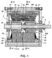
- Fig. 1 is a longitudinal sectional view of a motor/generator according to this invention.
- Fig. 2 is a cross-sectional view of the motor /generator along the line IIA ― IIA and the line IIB ― IIB in Fig. 1.
- Fig. 3 is a block diagram of a current control device for the motor/generator according to this invention.
- Fig. 4 is a longitudinal sectional view of a motor/generator according to a second embodiment of this invention.
- Fig. 5 is a cross -sectional view of the motor /generator according to the second embodiment of this invention taken along the line VA ― VA and the line VB ― VB in Fig. 4.
- Fig. 6 is a block diagram of a current control device for the motor/generator according to the second embodiment of this invention.
- Fig. 7 is similar to Fig. 6, but showing a third embodiment of this invention.
- Fig. 8 is a longitudinal sectional view of a motor/generator according to a fourth embodiment of this invention.
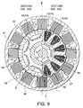
- Fig. 9 is a cross -sectional view of the motor /generator according to the fourth embodiment of this invention taken along the line IXA ― IXA and the line IXB ― IXB in Fig. 8.
- Fig. 10 is a longitudinal sectional view of a motor /generator according to a fifth embodiment of this invention.
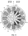
- Fig. 11 is a cross-sectional view of the motor/generator according to the fifth embodiment of this invention taken along line XIA ― XIA and the line XIB ― XIB in Fig. 10.
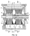
- Fig. 12 is a longitudinal sectional view of a motor /generator according to a sixth embodiment of this invention.
- Fig. 13 is a cross-sectional view of the motor/generator according to a sixth embodiment of this invention taken along the line XIIIA ― XIIIA and the line XIIIB ― XIIIB in Fig. 12.
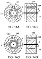
- Figs. 14A ― 14D are schematic longitudinal sectional and cross-sectional views of a motor/generator according to a seventh embodiment of this invention.
-
- Referring to Figs. 1 and 2, a motor/generator according to this invention is provided with a
stator 14, afirst rotor 2 and asecond rotor 3. - The
first rotor 2 is provided with arotation shaft 4 and thesecond rotor 3 Is provided with arotation shaft 5. Therotation shaft 4 has a cylindrical shape and therotation shaft 5 is fitted through therotation shaft 4. Therotation shafts rotation shaft 5 is supported by therotation shaft 4 throughneedle bearings rotation shaft 4 is supported on thecase 1 through a ball bearing 31. The outer periphery of one end of therotation shaft 5, positioned opposite the ball bearing 31, is supported on thecase 1 by a ball bearing 32. - The
first rotor 2 comprises sixmagnets 6. The second rotor comprises eightmagnets 7. However the number of magnets of thefirst rotor 2 and thesecond rotor 3 is not limited to the above number. - The
stator 14 comprises twelvecores 11 which are disposed to cover the outer periphery of thefirst rotor 2 and thesecond rotor 3. Eachcore 11 is made of magnetic plate members laminated in the direction of therotation shaft 5. Aslot 15 is formed betweenadjacent cores 11 to provide a space forstator coils 16 that are wound on thecores 11. - The
stator 14 is fitted inside thecylindrical case 1. Displacement of thecores 11 towards outer side is prevented by thecase 1. Retainingplates 18 parallel to therotation shaft 5 are disposed between eachcore 11. - A total of twelve retaining
plates 18 are disposed on a circumferential periphery.Ring grooves rings plates 18. - The retaining plates both ends of which are thus retained by the ring rings 21 and 22 prevent the
cores 11 from displacing to the inner side. The inner periphery of thecores 11 is also supported by a reinforcingring 25 disposed between thefirst rotor 2 and thesecond rotor 3. - When assembled, the outer peripheral sections of
adjacent cores 11 are in contact. On the other hand, the inner peripheral sections of thecores 11 project inwardly independently withstator coils 16 wound onto the projecting portions. - In this motor/generator, by supplying a first multi-phase alternating current having a phase difference of 90 degrees and a frequency determined by a required rotation speed of the
first rotor 2, to the twelve stator coils 16, thestator 14 generates a first rotating magnetic field which has three pairs of magnetic poles and which synchronously rotates thefirst rotor 2 at the required rotation speed. - On the other hand, by supplying a second multi-phase alternating current having a phase difference of 120 degrees and a frequency determined by a required rotation speed of the
second rotor 3, to the twelve stator coils 16, thestator 14 generate a second rotating magnetic field which has four pairs of magnetic poles and synchronously rotates thesecond rotor 3. - If a composite current of the first alternating current and the second alternating current is supplied to the twelve stator coils 16, the
stator 14 simultaneously generates the first and second rotating magnetic fields which respectively rotate the first andsecond rotors - The principle of this operation is described in USPat. 6,049,152.
- Control of the current supplied to the motor will be described with reference to Fig. 3.
- The motor is provided with a
battery 111, aninverter 112 and acontrol unit 115 in order to supply a composite alternating current to the stator coils 16. Theinverter 112 may be obtained by expanding a normal three-phase bridge-type inverter into twelve phase and is provided with twelve output terminals. Each output terminal is connected respectively with twelve stator coils 16. The end of eachstator coil 16 is connected to a terminatingpoint 16A. - The sum of the instantaneous current at the terminating
point 16A is always zero. - The
inverter 112 comprises twenty-four transistors and the same number of diodes, and a pulse width modulation (PWM) signal from thecontrol unit 115 is input to the base of each transistor. - Signals are input into the
control unit 115 from arotation angle sensor 113 detecting a rotation position of thefirst rotor 2 and arotation angle sensor 114 detecting a rotation position of thesecond rotor 3. Therotation angle sensors first rotor 2 and thesecond rotor 3 is input to thecontrol unit 115 as a command signal. Thecontrol unit 115 outputs the PWM signals to theinverter 112 based on the command signal and the rotational positions of thefirst rotor 2 and thesecond rotor 3. - Since this motor/generator drives the two
rotors inverter 112 and onestator 14, it is possible to reduce the capacitance of the transistors in comparison with a motor/generator having two inverters and stators to drive two rotors. Reduced switching loss is attained as a result. - This invention may also be applied to a case where one of the
first rotor 2 and thesecond rotor 3 serves as a generator for generating power while the other rotor serves as a motor rotating by the generated power. In this case, a current corresponding to the difference of the motor driving current and the generated current is supplied to the stator coils 16 from theinverter 112. - This electric power management much improves electrical efficiency of the motor/generator compared with the conventional electric power management in which power generated by a generator is once stored in a battery and a motor is driven by the power supplied from the battery.
- Furthermore, since the
first rotor 2 and thesecond rotor 3 are disposed In series along therotation shaft 5 and thestator 14 is disposed on an outer side of therotors stator 14 can be firmly secured to thecase 1. - In addition, the
first rotor 2 and thesecond rotor 3 are supported in a stable manner with respect to high velocity rotation since theneedle bearings ball bearings rotation shafts - Identical poles of the magnets of the
rotors rotors - A second embodiment of this invention will be described with reference to Figs. 4 ― 6.
- The motor /generator according to this embodiment differs from that of the first embodiment with respect to the structure of the
stator 14. Thestator 14 is provided with twelvefirst cores 11 facing thefirst rotor 2 and twelvesecond cores 12 facing thesecond rotor 3. Stator coils 16A are wound on thefirst cores 11. Stator coils 16B are wound onto thesecond cores 12. A reinforcingring 25 is disposed between thefirst cores 11 and thesecond cores 12 so as to abut with the inner periphery of the retaining plates and prevent them from displacing towards the inner side. The reinforcingring 25 also has the function of limiting displacement of thefirst cores 11 and thesecond cores 12 in the direction along therotation shaft 5. - Referring now to Fig. 6, a
stator coil 16A and astator coil 16B of the same phase are connected in parallel to one of the output terminals of theinverter 12. There are twelve pair ofstator coils point 16X of the stator coils 16A and that of a terminatingpoint 16Y of the stator coils 16B are always zero. The other components of the second embodiment are identical to those of the first embodiment. - This embodiment resembles two motor/generators arranged in an axial direction. However the
first rotor 2 and thesecond rotor 3 are independently driven by thesingle inverter 112 that supplies the composite alternating current to the stator coils 16A and 16B in the same manner as the first embodiment. - This embodiment also realizes a desirable supporting structure for the
stator 14, thefirst rotor 2 and thesecond rotor 3. - A third embodiment of this invention will be described with reference to Fig. 7.
- The disposition of the rotors and the stator in this embodiment is the same as the second embodiment. However the wiring of the stator coils 16A and 16B is different from that of the second embodiment.
- In this embodiment, the stator coils 16A and 16B of each phase are connected in series to each of the output terminals of the
inverter 112. Therefore only thestator coil 16B is provided with a terminatingpoint 16Y. In this embodiment, the instantaneous current of the terminatingpoint 16Y of the stator coils 16B has a value of zero. Thus it is possible to rotate thefirst rotor 2 and thesecond rotor 3 independently with a stable supporting structure. - A fourth embodiment of this invention will be described with reference to Figs. 8 and 9.
- In this embodiment, the
stator 14 comprises twelvefirst cores 11, twelvesecond cores 12 and twelvethird cores 13. Thefirst cores 11 are disposed on an outer side of thefirst rotor 11. Thesecond cores 12 are disposed on an outer side of thesecond rotor 3. Thethird cores 13 are disposed on an outer side of thefirst cores 11 and thesecond cores 12. Thethird core 13 of each phase electrically connects thefirst core 11 and thesecond core 12. The first andsecond cores rotating shaft 4. - Inward displacement of the
first cores 11 and thesecond cores 12 is limited by the retainingplates 18 and therings third cores 13 are made of magnetic plates laminated in the direction of the periphery of thecylindrical case 1 and are fitted respectively into the slots on the inner periphery of the case which is made of a non-magnetic material. Displacement towards the outer side of thefirst cores 11 and thesecond cores 12 is limited by the abutment of thethird cores 13 withfirst cores 11 andsecond cores 12 of the same phase.Indentations 46 are respectively formed on an outer periphery of thefirst cores 11 and thesecond cores 12. Aprojection 47 fitting into theindentation 46 is formed on an inner periphery of thethird cores 13. Thus displacement in the direction of the periphery of thefirst cores 11 and thesecond cores 12 is limited by theprojection 47 fitting into theindentation 46. - A wall of the
case 1 made of a non-magnetic material is interposed between adjacentthird cores 13. - In this embodiment, a magnetic flux is transmitted through the
third cores 13 betweenfirst cores 11 andsecond cores 12 of the same phase. - Therefore, leakage of magnetic flux between adjacent
second cores 12 and adjacentfirst cores 11 must be suppressed to low levels. In other words, magnetic resistance between adjacent cores in a circumferential periphery should be much greater than the magnetic resistance passing through thethird cores 13 betweenfirst cores 11 andsecond cores 12 of the same phase. - This requirement is satisfied by, for example, providing a space between adjacent cores or sandwiching a non-magnetic member between adjacent cores. For the same reason, it is preferred that the retaining
plates 18 is made of a non-magnetic material. - Stator coils 16 are wound on the
first cores 11. Coils are not wound on thesecond cores 12 and thethird cores 13. - In this motor/generator, it is possible to drive a
first rotor 2 and thesecond rotor 3 independently with a single inverter by applying a composite alternating current to twelve stator coils 16. - In this embodiment, the polarity of the inner periphery of the
first cores 11 is opposite to the polarity of the inner periphery of thesecond cores 12 of the same phase. This is due to the fact that thefirst cores 11 and thesecond cores 12 are electrically connected through thethird cores 13. In contrast, in the second embodiment, the inner periphery ofcores - A plurality of
first water jackets 40,second water jackets 41 and bolt holes 42 are formed approximately parallel to therotating shaft 4 in thecase 1 between thethird cores 13. The stator coils 16 are heated by variations in the magnetic flux, but the motor/generator is easily cooled by passing a liquid coolant through thewater jackets - The outer periphery of the
third cores 13 is covered with amagnetic shield 45 comprising a thin steel plate or a mesh plate. Theshield 45 prevents leakage out of thecase 1 of high frequency electromagnetic waves resulting from variations in magnetic flux inside thecase 1. - The structure of the
first rotor 2 and thesecond rotor 3 is the same as that described with reference to the first embodiment. However in this embodiment,ball bearings rotating shaft 4 and therotating shaft 5 instead of theneedle bearings - In this motor/generator, a reaction force is exerted on the
stator 14 when it rotates therotors - However, since the
third cores 13 of thestator 14 are respectively fitted into the slots of thecase 1, the supporting structure of thestator 14 is very stable. - Also, the
bearings first rotor 2 and thesecond rotor 3. - A fifth embodiment of this invention will be described with reference to Figs. 10 and 11.
- In this embodiment, the structure of the
stator 14 is different from that of the fourth embodiment. In this embodiment, thesecond cores 12 are replaced by projections formed on thethird cores 13. Thethird cores 13 are made of magnetic plates laminated in the direction of the periphery of thecylindrical case 1 In the same manner as the fourth embodiment. Also, thethird cores 13 are fitted into the slots of thecase 1. - The same effect as that of the fourth embodiment is obtained in this embodiment while the structure of the
stator 14 is simplified due to a fewer types of cores. - A sixth embodiment of this invention will be described with reference to Figs. 12 and 13.
- In this embodiment, the
stator 14, in the same manner as the second embodiment, is provided with twelvefirst cores 11 disposed on an outer side of thefirst rotor 2 and twelvesecond cores 12 which are disposed on an outer side of thesecond rotor 3. - Stator coils 16A are wound on the
first cores 11. Stator coils 16B are wound on thesecond cores 12. - However, in contradistinction to the second embodiment, the
third cores 13 are provided on an outer side of thefirst cores 11 and thesecond cores 12 in the same manner as the fourth embodiment. In this embodiment, thefirst cores 11 and thesecond cores 12 of the same phase are electrically connected through thethird cores 13. - Thus in contrast to the second embodiment, the polarity of the inner periphery of the
first cores 11 and the inner periphery ofsecond cores 12 of the same phase is opposite. The direction of winding of the stator coils 16A and 16B is preset not to interfere with this polarity characteristic. - In this embodiment also, various preferable effects similar to those of the fourth embodiment are obtained.
- In all the first to sixth embodiments above, the
first rotor 2 and thesecond rotor 3 are disposed along therotation shaft 5 and thestator 14 is disposed on an outer side of thestators rotors stator 14 to overlap in a radial direction. - A seventh embodiment of this invention will be described with reference to Figs. 14A -14D.
- In the first-sixth embodiments, the
first rotor 2 and thesecond rotor 3 are disposed co-axially along therotation shaft 5. Thefirst rotor 2 and thesecond rotor 3 are accommodated in asingle case 1 with thestator 14. - In this embodiment, the
rotating shaft 4 of thefirst rotor 2 and therotating shaft 5 of thesecond rotor 3 are not disposed co-axially. Thefirst rotor 2 is provided with a six-pole magnet 6 and thesecond rotor 3 is provided with an eight-pole magnet 7. Astator 14A creating a rotating magnetic field for thefirst rotor 2 and astator 14B creating a rotating magnetic field for thesecond rotor 3 are separately provided. Thestators coils stator 14A and thefirst rotor 2 are accommodated in acase 1A. Thestator 14B and thesecond rotor 3 are accommodated in acase 1B. -
Coils - In this embodiment, it is possible to drive two motor/generator units that are substantially independent from each other by a composite alternating current supplied from a single inverter. The only necessary condition for the motor/generators is that the number of poles of the
first rotor 1 and that of thesecond rotor 3 are different while the number ofcoils 16A of thestator 14A and the number ofcoils 16B of thestator 14B are the same. - The contents of Tokugan Hei 11-273303. with a filing date of September 27, 1999 in Japan, and Tokugan Hei 11-274874, with a filing date of September 28, 1999 in Japan, are hereby incorporated by reference.
- Although the invention has been described above by reference to certain embodiments of the invention, the invention is not limited to the embodiments described above. Modifications and variations of the embodiments described above will occur to those skilled in the art, in light of the above teachings.
- The embodiments of this invention in which an exclusive property or privilege is claimed are defined as follows:
Claims (19)
- A motor/generator comprising:a first rotation shaft (5);a first rotor (2) rotating with the first rotation shaft (5) and having a first number of magnetic poles that form a first magnetic field;a second rotation shaft (4) rotating relative to the first rotation shaft (5) and supported co-axially with the first rotation shaft (5);a second rotor (3) rotating with the second rotation shaft (4) and having a second number of magnetic poles that form a second magnetic field, the first number and the second number being different, the first rotor (2) and the second rotor (3) being disposed in series along the first rotation shaft (5);a stator (14) provided with coils (16, 16A, 16B) that generate a first rotating magnetic field in synchronism with the first magnetic field by application of a first alternating current, and generate a second rotating magnetic field in synchronism with the second magnetic field by application of a second alternating current; anda current control device (112, 115) that supplies a composite current comprising the first alternating current and the second alternating current to the coils (16, 16A, 16B).
- The motor/generator as defined in Claim 1, wherein the stator (14) is disposed facing an outer periphery of the first rotor (2) and the second rotor (3).
- The motor/generator as defined in Claim 2, wherein the stator (14) is provided with a plurality of core units (11, 12, 13) separated in a peripheral direction, each core unit (11, 12, 13) is provided with a first core (11) facing an outer periphery of the first rotor (2) and a second core (12, 13) facing an outer periphery of the second rotor (3) and magnetically connected with the first core (11), and a magnetic resistance between adjacent core units (11, 12, 13) is set to be greater than a magnetic resistance between the first core (11) and the second core (12, 13) of the same core unit (11, 12, 13).
- The motor/generator as defined in Claim 3, wherein each core unit (11, 12, 13) is further provided with a third core (13) magnetically connecting the first core (11) and the second core (12).
- The motor/generator as defined in Claim 4, wherein the first core (11) comprises magnetic steel plates laminated in the direction of the first rotation shalt (5), the second core (12) comprises magnetic steel plates laminated in the direction of the second rotation shaft (4), and the third core (13) comprises magnetic steel plates laminated in the direction of a periphery of the stator (14).
- The motor/generator as defined in Claim 3, wherein the first core (11) comprises magnetic steel plates laminated in the direction of the first rotation shaft (5),and the second core (12) comprises magnetic steel plates laminated in the direction of a periphery of the stator (14).
- The motor/generator as defined in Claim 1, wherein each of the coils (16, 16A) is wound on the first core (11) of each core unit (11, 12, 13).
- The motor/generator as defined in Claim 7, wherein the motor/generator is further provided with coils (16B) each of which is wound on the second core (12) of each core unit (11, 12, 13).
- The motor/generator as defined in Claim 3, wherein the stator (14) is accommodated in a case (1) that has a passage (40, 41) of liquid coolant, and supported inward by the case (1).
- The motor/generator as defined in Claim 3, wherein the motor/generator comprises a magnetic shield (45) surrounding an outer periphery of the stator (14).
- The motor/generator as defined in Claim 2, wherein the stator (4) comprises a plurality of cores (11) disposed adjacent to one another, each core (11) is provided with an inner peripheral part and an outer peripheral part, the outer peripheral part being in contact with an outer peripheral part of an adjacent core (11), the inner peripheral part projecting inward, and each of the coils (16) being wound on the inner peripheral part.
- The motor/generator as defined in Claim 1, wherein the stator (4) is provided with a plurality of first cores (11) facing an outer periphery of the first rotor (2) and an equal number of second cores (12) facing an outer periphery of the second rotor (3), each of the first cores (11) being provided with an inner peripheral part and an outer peripheral part, the outer peripheral part of the first core (11) being in contact with an outer peripheral part of an adjacent first core (11), the inner peripheral part of the first core (11) projecting inward, each of the second cores (12) being provided with an inner peripheral part and an outer peripheral part, the outer peripheral part of the second core (12) being in contact with an outer peripheral part of an adjacent second core (12), the inner peripheral part of the second cores (12) projecting inward, the coils (16, 16A, 16B) comprising first coils (16A) each of which is wound on the inner peripheral part of the first core (11), and second coils (16B) each of which is wound on the inner peripheral part of the second core (12).
- The motor/generator as defined in Claim 12, wherein the first coils (16A) and the second coils (16B) are connected in parallel to the current control device (112, 115).
- The motor/generator as defined in Claim 12, wherein the first coils (16A) and second coils (16B) are connected in series to the current control device (112, 115).
- The motor/generator as defined in Claim 1, wherein the first rotation shaft (5) penetrates the second rotation shaft (4), and the second rotation shaft (4) is supported by a plurality of bearings (30A, 30B, 45) so as to be free to rotate relative to the first rotation shaft (4).
- The motor/generator as defined in Claim 15, wherein the motor/generator further comprises a case (1) accommodating the stator (14), a bearing (32) supporting the first rotation shaft (5) on the case (1) and a bearing (33) supporting the second rotation shaft (4) on the case (1).
- A motor/generator comprising:a first rotation shaft (5);a first rotor (2) rotating with the first rotation shaft (5) and having a first number of magnetic poles that form a first magnetic field;a second rotation shaft (4) rotating relative to the first rotation shaft (5), the second rotation shaft (4) and the first rotation shaft (5) having different rotation axes;a second rotor (3) rotating with the second rotation shaft (4) and having a second number of magnetic poles that form a second magnetic field, the first number and the second number being different;a first stator (14A) provided with a third number of first coils (16A) that generate a first rotating magnetic field in synchronism with the first magnetic field by application of a first alternating current;a second stator (14B) provided with a fourth number of second coils (16B), the third number and the fourth number being equal, the second coils (16B) generating a rotating magnetic field in synchronism with second magnetic field by application of a second alternating current; anda current control device (112, 115) that supplies a composite current comprising the first alternating current and the second alternating current to the first coils (16A) and the second coils (16B).
- The motor/generator as defined in Claim 17, wherein the first coils (16A) and the second coils (16B) are connected in series to the current control device (112, 115).
- The motor/generator as defined in Claim 17, wherein the first coils (16A) and the second coils (16B) are connected in parallel to the current control device (112, 115).
Applications Claiming Priority (4)
| Application Number | Priority Date | Filing Date | Title |
|---|---|---|---|
| JP27330399 | 1999-09-27 | ||
| JP27330399A JP3663997B2 (en) | 1999-09-27 | 1999-09-27 | Multiple rotor motor |
| JP27487499 | 1999-09-28 | ||
| JP27487499A JP3511955B2 (en) | 1999-09-28 | 1999-09-28 | Compound motor |
Publications (3)
| Publication Number | Publication Date |
|---|---|
| EP1087501A2 true EP1087501A2 (en) | 2001-03-28 |
| EP1087501A3 EP1087501A3 (en) | 2003-09-03 |
| EP1087501B1 EP1087501B1 (en) | 2005-11-30 |
Family
ID=26550601
Family Applications (1)
| Application Number | Title | Priority Date | Filing Date |
|---|---|---|---|
| EP00120941A Expired - Lifetime EP1087501B1 (en) | 1999-09-27 | 2000-09-26 | Motor/generator with multiple rotors |
Country Status (3)
| Country | Link |
|---|---|
| US (1) | US6639337B1 (en) |
| EP (1) | EP1087501B1 (en) |
| DE (1) | DE60024383T2 (en) |
Cited By (4)
| Publication number | Priority date | Publication date | Assignee | Title |
|---|---|---|---|---|
| EP1330020A2 (en) * | 2002-01-16 | 2003-07-23 | Nissan Motor Company, Limited | Electric rotating machine and its connecting method |
| US6611127B2 (en) * | 2000-08-07 | 2003-08-26 | Nissan Motor Co., Ltd. | Drive circuit for motor/generator |
| WO2008080575A1 (en) * | 2006-12-29 | 2008-07-10 | Michael Thoms | Synchronous permanent magnet machine |
| EP2059996A1 (en) * | 2006-09-07 | 2009-05-20 | ABB Oy | Arrangement for cooling an electrical machine |
Families Citing this family (30)
| Publication number | Priority date | Publication date | Assignee | Title |
|---|---|---|---|---|
| JP3551164B2 (en) * | 2001-07-09 | 2004-08-04 | 日産自動車株式会社 | Current detection device for rotating electrical machines |
| JP3690355B2 (en) | 2002-02-12 | 2005-08-31 | 日産自動車株式会社 | Stator support structure for rotating electrical machines |
| JP3757890B2 (en) * | 2002-04-01 | 2006-03-22 | 日産自動車株式会社 | Driving method of rotating electric machine |
| US6958027B2 (en) * | 2002-11-14 | 2005-10-25 | Nissan Motor Co., Ltd. | Hybrid transmission |
| FR2861227B1 (en) * | 2003-10-21 | 2007-07-13 | Renault Sa | ELECTRIC MECHANICAL POWER TRANSMISSION, IN PARTICULAR FOR A MOTOR VEHICLE TRANSMISSION |
| JP4069859B2 (en) * | 2003-12-15 | 2008-04-02 | 日産自動車株式会社 | Structure of rotating electrical machine |
| US7230363B2 (en) * | 2004-03-30 | 2007-06-12 | Honeywell International, Inc. | Low profile generator configuration |
| JP2007082283A (en) * | 2005-09-12 | 2007-03-29 | Denso Corp | Alternator for vehicle |
| WO2007106134A2 (en) * | 2006-02-24 | 2007-09-20 | Norman Rittenhouse | Electrically driven tracked vehicle and suspension |
| DE602007011513D1 (en) * | 2006-03-06 | 2011-02-10 | Honda Motor Co Ltd | electric motor |
| WO2007102491A1 (en) * | 2006-03-06 | 2007-09-13 | Honda Motor Co., Ltd. | Motor |
| JP4620024B2 (en) * | 2006-03-06 | 2011-01-26 | 本田技研工業株式会社 | Electric motor |
| US7309938B1 (en) * | 2006-05-31 | 2007-12-18 | Smith Kelly S | Rotary power converter |
| FR2915523A1 (en) * | 2007-04-27 | 2008-10-31 | Snecma Sa | DEVICE FOR GENERATING ELECTRIC ENERGY IN A DOUBLE-BODY GAS TURBINE ENGINE |
| US20090167104A1 (en) * | 2008-01-02 | 2009-07-02 | Dunn Randy B | Stackable brushless DC motor |
| US8063501B2 (en) * | 2009-06-10 | 2011-11-22 | Hamilton Sundstrand Corporation | Gas turbine bleed energy recovery via counter rotating generator |
| US8258737B2 (en) * | 2009-06-24 | 2012-09-04 | Casey John R | Electric machine with non-coaxial rotors |
| US20110025157A1 (en) * | 2009-07-28 | 2011-02-03 | Rolls-Royce Corporation | System of electrical generation for counter-rotating open-rotor blade device |
| US8294316B2 (en) * | 2009-07-28 | 2012-10-23 | Rolls-Royce North American Technologies, Inc. | Electrical power generation apparatus for contra-rotating open-rotor aircraft propulsion system |
| WO2011144895A2 (en) | 2010-05-17 | 2011-11-24 | Magnomatics Limited | Large magnetically geared machines |
| GB0920148D0 (en) * | 2009-11-17 | 2009-12-30 | Magnomatics Ltd | Magnetically geared machine for marine generation |
| EP2792056A4 (en) * | 2011-12-16 | 2016-04-06 | Heron Energy Pte Ltd | High speed turbine |
| CN104638856A (en) * | 2013-11-06 | 2015-05-20 | 久鼎金属实业股份有限公司 | Dual-rotor motor for bike |
| DE102016117911A1 (en) | 2016-09-22 | 2018-03-22 | Volabo Gmbh | Electric machine |
| US9862289B1 (en) * | 2017-02-01 | 2018-01-09 | American Axle & Manufacturing, Inc. | Drive system with limited slip electric differential drive unit |
| EP3665764A4 (en) * | 2018-10-29 | 2020-10-21 | Ock Kee Baek | Autonomous electric generator for production of renewable, clean, portable, and sustainable energy |
| WO2020102775A1 (en) * | 2018-11-16 | 2020-05-22 | The Regents Of The University Of California | Gears for electric motor |
| CN109327092B (en) * | 2018-11-28 | 2020-01-21 | 华中科技大学 | Permanent magnet motor single winding setting method capable of generating two pole pairs |
| DE102021101408A1 (en) | 2021-01-22 | 2022-07-28 | Feaam Gmbh | ELECTRICAL MACHINE, POWER SYSTEM AND ITS USE |
| DE102021124127A1 (en) | 2021-09-17 | 2023-03-23 | Bayerische Motoren Werke Aktiengesellschaft | Compact drive arrangement with two coaxial electric drive machines |
Citations (4)
| Publication number | Priority date | Publication date | Assignee | Title |
|---|---|---|---|---|
| US4644207A (en) * | 1985-04-15 | 1987-02-17 | Rockwell International Corporation | Integrated dual pump system |
| FR2756118A1 (en) * | 1996-11-20 | 1998-05-22 | Moteurs Fox | Electric drive with flywheel energy storage for battery powered motor vehicles |
| JPH10257730A (en) * | 1997-03-07 | 1998-09-25 | Shinko Electric Co Ltd | Concentric multishaft motor |
| WO1999039426A1 (en) * | 1998-01-30 | 1999-08-05 | Schroedl Manfred | Electric machine |
Family Cites Families (22)
| Publication number | Priority date | Publication date | Assignee | Title |
|---|---|---|---|---|
| US3462626A (en) | 1966-12-30 | 1969-08-19 | Hughes Aircraft Co | Torque transferring arrangement |
| US3898490A (en) | 1973-09-24 | 1975-08-05 | Westinghouse Electric Corp | Superconductive AC dynamoelectric machines having two rotors |
| FI60326C (en) | 1976-03-25 | 1981-12-10 | Eriksson Jarl Thure | KOLLEKTERINGSANORDNING FOER OEVERFOERING AV ELEKTRISK STROEM MELLAN MINST ETT PAR ELEKTRISKA LEDARE VILKA KAN FOERSAETTAS I RELATIV ROTATIONSROERELSE KRING EN GEMENSAM AXEL |
| FR2517137B1 (en) | 1981-11-25 | 1985-11-15 | Cibie Pierre | ROTATING ELECTRICAL MACHINE FORMING IN PARTICULAR A SPEED VARIATOR OR TORQUE CONVERTER |
| US4503349A (en) | 1983-07-29 | 1985-03-05 | Westinghouse Electric Corp. | Self-excited high current DC electrical pulse generator |
| FR2572229B1 (en) | 1984-10-22 | 1987-04-17 | Rfb Electromecanismes | IMPROVED MAGNET ROTATING MACHINE |
| US4785213A (en) * | 1986-05-30 | 1988-11-15 | Satake Engineering Co., Ltd. | Variable speed controlled induction motor |
| JPH0625933B2 (en) | 1986-10-02 | 1994-04-06 | 科学技術庁航空宇宙技術研究所長 | Electric direct drive positioning device with compound eccentric rotor |
| DE3740697A1 (en) | 1987-12-01 | 1989-06-22 | Pfaff Ind Masch | DRIVE ENGINE |
| US5117141A (en) | 1990-07-30 | 1992-05-26 | The United States Of America As Represented By Department Of Energy | Disc rotors with permanent magnets for brushless DC motor |
| JPH06170675A (en) | 1992-12-04 | 1994-06-21 | Toshiba Mach Co Ltd | Dynamo-electric machine |
| JP3220535B2 (en) * | 1992-12-14 | 2001-10-22 | オリエンタルモーター株式会社 | Linear pulse motor |
| US6005317A (en) | 1993-05-21 | 1999-12-21 | Magna Force, Inc. | Adjustable magnetic coupler |
| JP3052786B2 (en) | 1995-06-09 | 2000-06-19 | 株式会社デンソー | Vehicle drive device and drive control method thereof |
| US5668430A (en) * | 1996-04-17 | 1997-09-16 | Dana Corporation | Dual-sectioned switched reluctance motor |
| US6121705A (en) | 1996-12-31 | 2000-09-19 | Hoong; Fong Chean | Alternating pole AC motor/generator with two inner rotating rotors and an external static stator |
| JP3099769B2 (en) * | 1997-03-24 | 2000-10-16 | トヨタ自動車株式会社 | Power output device and control method thereof |
| JP3480301B2 (en) | 1998-03-25 | 2003-12-15 | 日産自動車株式会社 | Rotating electric machine |
| DE69912504T2 (en) | 1998-03-25 | 2004-05-06 | Nissan Motor Co., Ltd., Yokohama | Motor / generator |
| JP3719136B2 (en) | 2000-01-17 | 2005-11-24 | 日産自動車株式会社 | Rotating electric machine and drive system |
| US6304017B1 (en) | 2000-02-18 | 2001-10-16 | The United States Of America As Represented By The Secretary Of The Army | Counter rotating nested cylinders in electrical machinery |
| JP2001298920A (en) | 2000-04-18 | 2001-10-26 | Tamagawa Seiki Co Ltd | Two-shaft concentric motor |
-
2000
- 2000-09-25 US US09/668,348 patent/US6639337B1/en not_active Expired - Fee Related
- 2000-09-26 DE DE60024383T patent/DE60024383T2/en not_active Expired - Lifetime
- 2000-09-26 EP EP00120941A patent/EP1087501B1/en not_active Expired - Lifetime
Patent Citations (4)
| Publication number | Priority date | Publication date | Assignee | Title |
|---|---|---|---|---|
| US4644207A (en) * | 1985-04-15 | 1987-02-17 | Rockwell International Corporation | Integrated dual pump system |
| FR2756118A1 (en) * | 1996-11-20 | 1998-05-22 | Moteurs Fox | Electric drive with flywheel energy storage for battery powered motor vehicles |
| JPH10257730A (en) * | 1997-03-07 | 1998-09-25 | Shinko Electric Co Ltd | Concentric multishaft motor |
| WO1999039426A1 (en) * | 1998-01-30 | 1999-08-05 | Schroedl Manfred | Electric machine |
Non-Patent Citations (1)
| Title |
|---|
| PATENT ABSTRACTS OF JAPAN vol. 1998, no. 14, 31 December 1998 (1998-12-31) & JP 10 257730 A (SHINKO ELECTRIC CO LTD), 25 September 1998 (1998-09-25) * |
Cited By (7)
| Publication number | Priority date | Publication date | Assignee | Title |
|---|---|---|---|---|
| US6611127B2 (en) * | 2000-08-07 | 2003-08-26 | Nissan Motor Co., Ltd. | Drive circuit for motor/generator |
| EP1330020A2 (en) * | 2002-01-16 | 2003-07-23 | Nissan Motor Company, Limited | Electric rotating machine and its connecting method |
| EP1330020A3 (en) * | 2002-01-16 | 2005-03-02 | Nissan Motor Company, Limited | Electric rotating machine and its connecting method |
| EP2059996A1 (en) * | 2006-09-07 | 2009-05-20 | ABB Oy | Arrangement for cooling an electrical machine |
| EP2059996A4 (en) * | 2006-09-07 | 2012-06-27 | Abb Oy | Arrangement for cooling an electrical machine |
| WO2008080575A1 (en) * | 2006-12-29 | 2008-07-10 | Michael Thoms | Synchronous permanent magnet machine |
| US7944107B2 (en) | 2006-12-29 | 2011-05-17 | Michael Thoms | Synchronous permanent magnet machine |
Also Published As
| Publication number | Publication date |
|---|---|
| DE60024383D1 (en) | 2006-01-05 |
| DE60024383T2 (en) | 2006-06-22 |
| EP1087501B1 (en) | 2005-11-30 |
| EP1087501A3 (en) | 2003-09-03 |
| US6639337B1 (en) | 2003-10-28 |
Similar Documents
| Publication | Publication Date | Title |
|---|---|---|
| US6639337B1 (en) | Motor/generator with multiple rotors | |
| JP6977556B2 (en) | Rotating machine | |
| US6798104B2 (en) | Rotary electric machine for electric vehicle | |
| US9537362B2 (en) | Electrical machine with improved stator flux pattern across a rotor for providing high torque density | |
| US20210234415A1 (en) | Rotating electric machine | |
| EP2226924A1 (en) | Motor and rotor for dynamo-electric machine | |
| KR20070119055A (en) | Motor | |
| JP6388611B2 (en) | Hybrid field double gap synchronous machine | |
| EP0817360B1 (en) | Hybrid type stepping motor | |
| US20110163641A1 (en) | Permanent-magnet synchronous motor | |
| CN100525008C (en) | Three-phase synchronous reluctance motor | |
| US5834866A (en) | Motor structure | |
| US5864197A (en) | Synchronous machine | |
| JP2000209825A (en) | Permanent magnet generator | |
| US6781260B2 (en) | Permanent magnet type rotary machine | |
| US7233093B2 (en) | Electric rotating machine | |
| JP5301905B2 (en) | Multi-phase rotating electrical machine drive device, multi-phase generator converter, multi-phase rotating electrical machine, and rotating electrical machine drive system | |
| JP3663997B2 (en) | Multiple rotor motor | |
| WO2024085919A1 (en) | Double rotor brushless direct-current motor with fluid cooling | |
| JP2010516224A (en) | Multi-phase drive or generator machine | |
| JP6451990B2 (en) | Rotating electric machine | |
| JP2018102090A (en) | Stator and motor | |
| JP2001119875A (en) | Synchronous machine and rotating electric machine for electric vehicle using the same | |
| US20100194227A1 (en) | Power generator | |
| JP3719121B2 (en) | Rotating electric machine |
Legal Events
| Date | Code | Title | Description |
|---|---|---|---|
| PUAI | Public reference made under article 153(3) epc to a published international application that has entered the european phase |
Free format text: ORIGINAL CODE: 0009012 |
|
| 17P | Request for examination filed |
Effective date: 20000926 |
|
| AK | Designated contracting states |
Kind code of ref document: A2 Designated state(s): AT BE CH CY DE DK ES FI FR GB GR IE IT LI LU MC NL PT SE |
|
| AX | Request for extension of the european patent |
Free format text: AL;LT;LV;MK;RO;SI |
|
| PUAL | Search report despatched |
Free format text: ORIGINAL CODE: 0009013 |
|
| AK | Designated contracting states |
Kind code of ref document: A3 Designated state(s): AT BE CH CY DE DK ES FI FR GB GR IE IT LI LU MC NL PT SE |
|
| AX | Request for extension of the european patent |
Extension state: AL LT LV MK RO SI |
|
| RIC1 | Information provided on ipc code assigned before grant |
Ipc: 7H 02K 17/02 A Ipc: 7H 02P 6/00 B Ipc: 7H 02K 16/00 B Ipc: 7H 02K 16/02 B |
|
| 17Q | First examination report despatched |
Effective date: 20040105 |
|
| AKX | Designation fees paid |
Designated state(s): DE FR GB |
|
| GRAP | Despatch of communication of intention to grant a patent |
Free format text: ORIGINAL CODE: EPIDOSNIGR1 |
|
| GRAS | Grant fee paid |
Free format text: ORIGINAL CODE: EPIDOSNIGR3 |
|
| GRAA | (expected) grant |
Free format text: ORIGINAL CODE: 0009210 |
|
| AK | Designated contracting states |
Kind code of ref document: B1 Designated state(s): DE FR GB |
|
| REG | Reference to a national code |
Ref country code: GB Ref legal event code: FG4D |
|
| REF | Corresponds to: |
Ref document number: 60024383 Country of ref document: DE Date of ref document: 20060105 Kind code of ref document: P |
|
| ET | Fr: translation filed | ||
| PLBE | No opposition filed within time limit |
Free format text: ORIGINAL CODE: 0009261 |
|
| STAA | Information on the status of an ep patent application or granted ep patent |
Free format text: STATUS: NO OPPOSITION FILED WITHIN TIME LIMIT |
|
| 26N | No opposition filed |
Effective date: 20060831 |
|
| PGFP | Annual fee paid to national office [announced via postgrant information from national office to epo] |
Ref country code: GB Payment date: 20090923 Year of fee payment: 10 |
|
| PGFP | Annual fee paid to national office [announced via postgrant information from national office to epo] |
Ref country code: DE Payment date: 20090923 Year of fee payment: 10 |
|
| PGFP | Annual fee paid to national office [announced via postgrant information from national office to epo] |
Ref country code: FR Payment date: 20091012 Year of fee payment: 10 |
|
| GBPC | Gb: european patent ceased through non-payment of renewal fee |
Effective date: 20100926 |
|
| REG | Reference to a national code |
Ref country code: FR Ref legal event code: ST Effective date: 20110531 |
|
| REG | Reference to a national code |
Ref country code: DE Ref legal event code: R119 Ref document number: 60024383 Country of ref document: DE Effective date: 20110401 |
|
| PG25 | Lapsed in a contracting state [announced via postgrant information from national office to epo] |
Ref country code: FR Free format text: LAPSE BECAUSE OF NON-PAYMENT OF DUE FEES Effective date: 20100930 Ref country code: DE Free format text: LAPSE BECAUSE OF NON-PAYMENT OF DUE FEES Effective date: 20110401 |
|
| PG25 | Lapsed in a contracting state [announced via postgrant information from national office to epo] |
Ref country code: GB Free format text: LAPSE BECAUSE OF NON-PAYMENT OF DUE FEES Effective date: 20100926 |