DE69912504T2 - Motor / generator - Google Patents
Motor / generator Download PDFInfo
- Publication number
- DE69912504T2 DE69912504T2 DE69912504T DE69912504T DE69912504T2 DE 69912504 T2 DE69912504 T2 DE 69912504T2 DE 69912504 T DE69912504 T DE 69912504T DE 69912504 T DE69912504 T DE 69912504T DE 69912504 T2 DE69912504 T2 DE 69912504T2
- Authority
- DE
- Germany
- Prior art keywords
- rotor
- coils
- motor
- equation
- generator
- Prior art date
- Legal status (The legal status is an assumption and is not a legal conclusion. Google has not performed a legal analysis and makes no representation as to the accuracy of the status listed.)
- Expired - Lifetime
Links
Classifications
-
- H—ELECTRICITY
- H02—GENERATION; CONVERSION OR DISTRIBUTION OF ELECTRIC POWER
- H02K—DYNAMO-ELECTRIC MACHINES
- H02K16/00—Machines with more than one rotor or stator
- H02K16/02—Machines with one stator and two or more rotors
-
- H—ELECTRICITY
- H02—GENERATION; CONVERSION OR DISTRIBUTION OF ELECTRIC POWER
- H02P—CONTROL OR REGULATION OF ELECTRIC MOTORS, ELECTRIC GENERATORS OR DYNAMO-ELECTRIC CONVERTERS; CONTROLLING TRANSFORMERS, REACTORS OR CHOKE COILS
- H02P6/00—Arrangements for controlling synchronous motors or other dynamo-electric motors using electronic commutation dependent on the rotor position; Electronic commutators therefor
- H02P6/10—Arrangements for controlling torque ripple, e.g. providing reduced torque ripple
-
- H—ELECTRICITY
- H02—GENERATION; CONVERSION OR DISTRIBUTION OF ELECTRIC POWER
- H02K—DYNAMO-ELECTRIC MACHINES
- H02K11/00—Structural association of dynamo-electric machines with electric components or with devices for shielding, monitoring or protection
- H02K11/20—Structural association of dynamo-electric machines with electric components or with devices for shielding, monitoring or protection for measuring, monitoring, testing, protecting or switching
- H02K11/21—Devices for sensing speed or position, or actuated thereby
-
- H—ELECTRICITY
- H02—GENERATION; CONVERSION OR DISTRIBUTION OF ELECTRIC POWER
- H02K—DYNAMO-ELECTRIC MACHINES
- H02K21/00—Synchronous motors having permanent magnets; Synchronous generators having permanent magnets
- H02K21/02—Details
-
- H—ELECTRICITY
- H02—GENERATION; CONVERSION OR DISTRIBUTION OF ELECTRIC POWER
- H02K—DYNAMO-ELECTRIC MACHINES
- H02K51/00—Dynamo-electric gears, i.e. dynamo-electric means for transmitting mechanical power from a driving shaft to a driven shaft and comprising structurally interrelated motor and generator parts
-
- H—ELECTRICITY
- H02—GENERATION; CONVERSION OR DISTRIBUTION OF ELECTRIC POWER
- H02M—APPARATUS FOR CONVERSION BETWEEN AC AND AC, BETWEEN AC AND DC, OR BETWEEN DC AND DC, AND FOR USE WITH MAINS OR SIMILAR POWER SUPPLY SYSTEMS; CONVERSION OF DC OR AC INPUT POWER INTO SURGE OUTPUT POWER; CONTROL OR REGULATION THEREOF
- H02M7/00—Conversion of ac power input into dc power output; Conversion of dc power input into ac power output
-
- H—ELECTRICITY
- H02—GENERATION; CONVERSION OR DISTRIBUTION OF ELECTRIC POWER
- H02P—CONTROL OR REGULATION OF ELECTRIC MOTORS, ELECTRIC GENERATORS OR DYNAMO-ELECTRIC CONVERTERS; CONTROLLING TRANSFORMERS, REACTORS OR CHOKE COILS
- H02P6/00—Arrangements for controlling synchronous motors or other dynamo-electric motors using electronic commutation dependent on the rotor position; Electronic commutators therefor
- H02P6/08—Arrangements for controlling the speed or torque of a single motor
-
- H—ELECTRICITY
- H02—GENERATION; CONVERSION OR DISTRIBUTION OF ELECTRIC POWER
- H02P—CONTROL OR REGULATION OF ELECTRIC MOTORS, ELECTRIC GENERATORS OR DYNAMO-ELECTRIC CONVERTERS; CONTROLLING TRANSFORMERS, REACTORS OR CHOKE COILS
- H02P6/00—Arrangements for controlling synchronous motors or other dynamo-electric motors using electronic commutation dependent on the rotor position; Electronic commutators therefor
- H02P6/28—Arrangements for controlling current
-
- B—PERFORMING OPERATIONS; TRANSPORTING
- B60—VEHICLES IN GENERAL
- B60K—ARRANGEMENT OR MOUNTING OF PROPULSION UNITS OR OF TRANSMISSIONS IN VEHICLES; ARRANGEMENT OR MOUNTING OF PLURAL DIVERSE PRIME-MOVERS IN VEHICLES; AUXILIARY DRIVES FOR VEHICLES; INSTRUMENTATION OR DASHBOARDS FOR VEHICLES; ARRANGEMENTS IN CONNECTION WITH COOLING, AIR INTAKE, GAS EXHAUST OR FUEL SUPPLY OF PROPULSION UNITS IN VEHICLES
- B60K1/00—Arrangement or mounting of electrical propulsion units
- B60K1/02—Arrangement or mounting of electrical propulsion units comprising more than one electric motor
-
- B—PERFORMING OPERATIONS; TRANSPORTING
- B60—VEHICLES IN GENERAL
- B60K—ARRANGEMENT OR MOUNTING OF PROPULSION UNITS OR OF TRANSMISSIONS IN VEHICLES; ARRANGEMENT OR MOUNTING OF PLURAL DIVERSE PRIME-MOVERS IN VEHICLES; AUXILIARY DRIVES FOR VEHICLES; INSTRUMENTATION OR DASHBOARDS FOR VEHICLES; ARRANGEMENTS IN CONNECTION WITH COOLING, AIR INTAKE, GAS EXHAUST OR FUEL SUPPLY OF PROPULSION UNITS IN VEHICLES
- B60K6/00—Arrangement or mounting of plural diverse prime-movers for mutual or common propulsion, e.g. hybrid propulsion systems comprising electric motors and internal combustion engines ; Control systems therefor, i.e. systems controlling two or more prime movers, or controlling one of these prime movers and any of the transmission, drive or drive units Informative references: mechanical gearings with secondary electric drive F16H3/72; arrangements for handling mechanical energy structurally associated with the dynamo-electric machine H02K7/00; machines comprising structurally interrelated motor and generator parts H02K51/00; dynamo-electric machines not otherwise provided for in H02K see H02K99/00
- B60K6/20—Arrangement or mounting of plural diverse prime-movers for mutual or common propulsion, e.g. hybrid propulsion systems comprising electric motors and internal combustion engines ; Control systems therefor, i.e. systems controlling two or more prime movers, or controlling one of these prime movers and any of the transmission, drive or drive units Informative references: mechanical gearings with secondary electric drive F16H3/72; arrangements for handling mechanical energy structurally associated with the dynamo-electric machine H02K7/00; machines comprising structurally interrelated motor and generator parts H02K51/00; dynamo-electric machines not otherwise provided for in H02K see H02K99/00 the prime-movers consisting of electric motors and internal combustion engines, e.g. HEVs
- B60K6/22—Arrangement or mounting of plural diverse prime-movers for mutual or common propulsion, e.g. hybrid propulsion systems comprising electric motors and internal combustion engines ; Control systems therefor, i.e. systems controlling two or more prime movers, or controlling one of these prime movers and any of the transmission, drive or drive units Informative references: mechanical gearings with secondary electric drive F16H3/72; arrangements for handling mechanical energy structurally associated with the dynamo-electric machine H02K7/00; machines comprising structurally interrelated motor and generator parts H02K51/00; dynamo-electric machines not otherwise provided for in H02K see H02K99/00 the prime-movers consisting of electric motors and internal combustion engines, e.g. HEVs characterised by apparatus, components or means specially adapted for HEVs
- B60K6/26—Arrangement or mounting of plural diverse prime-movers for mutual or common propulsion, e.g. hybrid propulsion systems comprising electric motors and internal combustion engines ; Control systems therefor, i.e. systems controlling two or more prime movers, or controlling one of these prime movers and any of the transmission, drive or drive units Informative references: mechanical gearings with secondary electric drive F16H3/72; arrangements for handling mechanical energy structurally associated with the dynamo-electric machine H02K7/00; machines comprising structurally interrelated motor and generator parts H02K51/00; dynamo-electric machines not otherwise provided for in H02K see H02K99/00 the prime-movers consisting of electric motors and internal combustion engines, e.g. HEVs characterised by apparatus, components or means specially adapted for HEVs characterised by the motors or the generators
Description
GEBIET DER ERFINDUNGAREA OF INVENTION
Diese Erfindung betrifft den Aufbau eines Motor/Generators.This invention relates to the structure a motor / generator.
HINTERGRUND DER ERFINDUNGBACKGROUND THE INVENTION
Tokkai HEI 8-340663, veröffentlicht
von dem Japanischen Patentamt 1996 und die zugehörige Europäische Patentanmeldung
ZUSAMMENFASSUNG DER ERFINDUNGSUMMARY THE INVENTION
In dem Falle dieses Motor/Generators gibt es, da zwei Sätze von Spulen und Umrichtern erforderlich sind, ein Problem dahingehend, dass Stromverluste, wie z. B. der Kupferverlust und Schaltverlust groß sind.In the case of this motor / generator there are two sentences of coils and converters are required, a problem in that that power losses, such as B. copper loss and switching loss are great.
Es ist daher eine Aufgabe dieser Erfindung, die Stromverluste eines derartigen dreilagigen Motor/Generators, wie er in der herkömmlichen Technik beschriebenen ist, zu verringern.It is therefore a task of this Invention, the current losses of such a three-layer motor / generator, as in the conventional Technology described is to reduce.
Zur Lösung dieser Aufgaben stellt die vorliegende Erfindung einen Motor/Generator bereit, welcher einen ersten Rotor, der mehrere magnetische Pole umfasst und für eine freie Rotation gelagert ist, einen zweiten Rotor, welcher mehrere magnetische Pole umfasst und für eine freie Rotation koaxial zu dem ersten Rotor gelagert ist, einen Stator, welcher koaxial zu dem ersten Rotor befestigt ist, und eine Spuleneinheit umfasst, wel che mehrere Spulen umfasst, die in gleichen Winkelintervallen auf dem Stator angeordnet sind, wobei die Spuleneinheit rotierende magnetische Felder mit gleicher Anzahl wie die Anzahl magnetischer Pole des ersten Rotors gemäß einem ersten daran angelegten Wechselstrom erzeugt und rotierende magnetische Felder mit gleicher Anzahl wie die Anzahl magnetischer Pole des zweiten Rotors gemäß einem zweiten daran angelegten Wechselstrom erzeugt, und eine Regelung mit der Funktion einen zusammengesetzten elektrischen Strom, welcher den ersten Wechselstrom und den zweiten Wechselstrom umfasst, der Spuleneinheit zuzuführen.To solve these tasks the present invention provides a motor / generator which a first rotor, which comprises several magnetic poles and for a free one Rotation is mounted, a second rotor, which has several magnetic Pole covers and for a free rotation is mounted coaxially to the first rotor, one Stator, which is fixed coaxially to the first rotor, and one Includes coil unit, which comprises several coils that are in the same Angular intervals are arranged on the stator, the coil unit rotating magnetic fields with the same number as the number magnetic pole of the first rotor according to a first applied to it Alternating current generated and rotating magnetic fields with the same Number as the number of magnetic poles of the second rotor according to one second AC power applied to it, and regulation with the function of a composite electric current, which includes the first alternating current and the second alternating current, the Feed coil unit.
Die Details, sowie weitere Merkmale und Vorteile dieser Erfindung werden in dem Rest der Beschreibung ausgeführt und sind in den beigefügten Zeichnungen dargestellt.The details, as well as other features and advantages of this invention will appear in the rest of the description accomplished and are attached in the Drawings shown.
KURZBESCHREIBUNG DER ZEICHNUNGENSUMMARY THE DRAWINGS
BESCHREIBUNG DER BEVORZUGTEN AUSFÜHRUNGSFORMENDESCRIPTION OF THE PREFERRED EMBODIMENTS
Gemäß
Der Stator
Gemäß Darstellung in
Der Aussenrotor
Gemäß dieser Anordnung üben wegen
des nachstehenden Grundes die rotierenden magnetischen Felder bezüglich des
Aussenrotors
Es werde angenommen, dass in dem
in
Der Stator
Die Kerne
Zur Vereinfachung sind die in
Ströme I1–I12 werden in diese zwölf Spulen #1–#12 geleitet.Currents I 1 - I 12 are conducted into these twelve coils # 1 - # 12.
Zuerst wird ein Drei-Phasen-Wechselstrom
in drei Spulensätze
geleitet, um ein rotierendes Magnetfeld in Bezug auf den Innenrotor
In ähnlicher Weise bilden die Spulen #3, #4, #9, #10 einen Satz, und ein Strom 1e fließt durch diese Spulen, als ob sie eine virtuelle Spule um eine weitere virtuelle Achse, die um 120° aus der vorstehend erwähnten virtuellen Achse gedreht ist, bilden würde.The coils form in a similar manner # 3, # 4, # 9, # 10 one sentence, and a current 1e flows through these coils as if they were a virtual coil around another virtual Axis that out by 120 ° the aforementioned virtual axis is rotated, would form.
Ferner bilden die restlichen Spulen #5, #6, #11, #12 eine virtuelle Spule um eine weitere virtuelle Achse, die um 120° gedreht ist, und ein Strom 1f fließt durch diese Spulen.Furthermore, the remaining coils form # 5, # 6, # 11, # 12 one virtual coil around another virtual one Axis rotated by 120 ° and a current 1f flows through these coils.
Somit sind drei virtuelle Spulen
mit Wicklungsachsen ausgebildet, welche sich um 120° unterscheiden, und
ein N-Pol – und
ein S-Pol-Bereich wird alle 180° wie
in dem Falle des Innenrotors
In dieser Ausführungsform wird der Stromfluss
in der Form dargestellt
Eine Spule mit einer unterstrichenen Zahl bedeutet, dass ein Strom in der umgekehrten Richtung zu der einer Spule mit einer nicht unterstrichenen Zahl geleitet wird.A coil with an underlined Number means that there is a current in the opposite direction to that a coil with an unlined line.
Anschließend wird ein Drei-Phasen-Strom
in die drei Spulensätze
anhand der nachstehenden Kombination geleitet, um so ein Magnetfeld
in Bezug auf den Aussenrotor
Mit anderen Worten, ein Strom Ia
wird der Spule #4 aus der Spule #1 zugeführt, und ein Strom Ia fließt zu der
Spule #10 aus der Spule #7. Indem eine einen Zwischenpunkt zwischen
der Spule #4 und #4 und einen Zwischenpunkt zwischen der Spule #7
und #10 in
Da der Stromfluss dieser virtuellen
Spulen in entgegengesetzten Richtungen stattfindet, wird ein N-Pol beispielsweise
den zwei Enden der virtuellen Achse und ein S-Pol in der Nähe der Rotationsachse
des Rotors
In ähnlicher Weise wird für die Spulen
#2, #5, #8 und #10 ein Strom Ib durchgeleitet. In ähnlicher
Weise wird für
die Spulen #3, #6, #11 und #12 ein Strom 1c durchgeleitet. Daher
werden vierpolige rotierende magnetische Felder in Bezug auf den
Aussenrotor
Um die vorstehenden Bedingungen zu
erfüllen,
sollten die nachstehenden Ströme
I1–I12 durch die zwölf Spulen

Ein Strom in der umgekehrten Richtung wird durch eine dem Stromsymbol hinzugefügte Unterstreichung dargestellt.A current in the opposite direction is represented by an underline added to the stream symbol.
Anschließend wird unter Bezugnahme
auf
Mit anderen Worten, die Innenspulen
d, f, e bilden rotierende magnetische Felder in Bezug auf den Innenrotor
Um diese Gruppen von Spulen in die
in
Wenn diese Stromfestlegung angewendet
wird, können
zwei rotierende magnetische Felder gleichzeitig gebildet werden,
d. h., rotierende magnetische Felder in Bezug auf den Innenrotor
Die Frequenz der Ströme 1d, 1f,
1e wird auf der Basis einer Sollrotationsdrehzahl des Innenrotors
Die Regelung des Motor/Generators
Die Regelungseinrichtung weist einen
Umrichter
Ein an jedes Gatter des Umrichters
Rotationswinkelsensoren
Das PWM-Signal wird in der Regelschaltung
Auf diese Weise sind in diesem Motor/Generator
zwei Rotoren
Daher kann, wenn einer der Rotoren
Ferner können, da die Rotation der zwei
Rotoren
Anschließend wird eine zweite Ausführungsform
der Erfindung unter Bezugnahme auf
In
Durch Ausbilden des Stators
Nachstehend wird eine dritten Ausführungsform
unter Bezugnahme auf
In den vorstehend erwähnten ersten
und zweiten Ausführungsformen
war das Verhältnis
der magnetischen Pole des Aussenrotors
Wenn das Magnetpol-Anzahlverhältnis 3
: 1 ist, sind die Permanentmagnete des Aussenrotors
Daher kann diese Drehmomentfluktuation
aufgehoben werden, indem vorab eine Amplitudenmodulation den Wechselströmen hinzugefügt wird,
welche die rotierenden magnetischen Felder bezüglich des Aussenrotors
Daher kann selbst in dieser Ausführungsform, bei der das Magnetpol-Anzahlverhältnis 3 : 1 ist, im wesentlichen derselbe Effekt erzielt werden, als das Magnetpol-Anzahlverhältnis 2 : 1 ist,Therefore, even in this embodiment, where the magnetic pole number ratio 3: 1, essentially the same effect can be achieved as that Magnetic pole number ratio Is 2: 1,
Der Aufbau, in welchem drei Spulen
in Bezug auf nur einen magnetischen Pol des Aussenrotors
Die nachstehenden Ströme I1–I18 werden in diese achtzehn Spulen #1–#18 geleitet.The following currents I 1 -I 18 are conducted into these eighteen coils # 1 - # 18.

Hierin stellen Stromnummern mit Unterstreichung
Ströme
in umgekehrter Richtung dar. Die Stöme Ia–If entsprechen den in die
Spule a–f
in
In den vorstehenden Gleichungen sind I10–I18 die umgekehrten von I1–I9. Somit wird, wenn das Magnetpol-Anzahlverhältnis 3 : 1 ist, die Phase über den halben Umfang hinweg umgekehrt.In the above equations, I 10 -I 18 are the inverse of I 1 -I 9 . Thus, when the magnetic pole number ratio is 3: 1, the phase is reversed half way around.
Trotz der Tatsache, dass ein Achtzehn-Phasen-Strom erforderlich ist, kann, da die Stromphase alle 180° umgekehrt wird, ein Umrichter verwendet werden, welcher einen Neun-Phasen-Wechslstrom erzeugt, um die vorstehend bestimmten Ströme I1–I18 zu erzeugen. Der Umrichter kann daher aus achtzehn Transistoren und achtzehn Dioden aufgebaut werden, weshalb die Anzahl der Transistoren und Dioden im Vergleich zu den vorstehend erwähnten ersten und zweiten Ausführungsformen reduziert werden kann.Despite the fact that an eighteen-phase current is required, since the current phase is reversed every 180 °, an inverter can be used which generates a nine-phase alternating current to the currents I 1 -I 18 determined above produce. The converter can therefore be constructed from eighteen transistors and eighteen diodes, and therefore the number of transistors and diodes can be reduced compared to the first and second embodiments mentioned above.
Anschließend wird eine vierte Ausführungsform
dieser Erfindung unter Bezugnahme auf
In dieser Ausführungsform wird die Anzahl
der Herstellungsschritte des Motor/Generators weiter im Vergleich
zu der dritten Ausführungsform
verringert, indem die Spulen
In dieser Ausführungsform ist kein Spalt
Obwohl das Magnetpol-Anzahlverhältnis 2
: 1 in den ersten und zweiten Ausführungsformen, und 3 : 1 in
den dritten und vierten Ausführungsformen
war, sind weitere Magnetpol-Anzahlverhältnisse
möglich.
Aus der nachstehenden theoretischen Analyse wird man erkennen, dass
der Aussenrotor
Anschließend wird die theoretische Analyse der auf die Rotoren wirkenden Antriebskräfte unter Bezugnahme auf die Magnetpol-Anzahlverhältnisse durchgeführt.Then the theoretical Analysis of the driving forces acting on the rotors with reference to the Magnetic pole number ratios carried out.
(1)N(2p-2p)–TYP(1) N (2p-2p) type
Zuerst stellt bei der Beschreibung
der Bezeichnung N(2p-2p)2p auf der linken Seite die Anzahl der Magnetpole
der Permanentmagnete des Aussenrotors
N ist eine positive ganze Zahl. Wenn
N 1 ist, ist die Magnetpolanzahl sowohl des Aussenrotors
(1-1) Basisformeln(1-1) Basic formulas
In
μ =
magnetische Permeabilität
ist,
Im1 = äquivalente Gleichstrom der äusseren
Magnete;
Im2 = äquivalenter Gleichstrom inneren
Magnete,
ω1 = Rotationswinkelgeschwindigkeit der äusseren
Magnete,
ω2 = Rotationsgeschwindigkeit der inneren
Magnete,
α =
Phasendifferenz der Außen – und inneren
Magnete (wenn t = 0), und
t = verstrichene Zeit von dem Zeitpunkt
an, wenn die Phase der äusseren
Magneten und der Statorspule übereinstimmten.In
μ = magnetic permeability,
Im 1 = equivalent direct current of the outer magnets;
Im 2 = equivalent direct current inner magnets,
ω 1 = rotational angular velocity of the outer magnets,
ω 2 = rotation speed of the inner magnets,
α = phase difference of the outer and inner magnets (if t = 0), and
t = elapsed time from when the phase of the outer magnets and the stator coil matched.
Wenn der durch den Stator geleitete
Strom ein Drei-Phasen-Wechselstrom ist, wird die magnetische Flussdichte
Bc aufgrund der Statorspule durch die nachstehende Gleichung (3)
ausgedrückt. ![]()
![]()
In Gleichung (3) sind Ica(t), Icb(t), Icc(t) Ströme, welche in der Phase um 120° verschoben sind.In equation (3) Ica (t), Icb (t), Icc (t) currents, which is shifted in phase by 120 ° are.
Die Veränderung der vorstehend erwähnten magnetischen
Flussdichten B1, B2 und
Bc ist in

Hier sei das auf den Aussenrotor
Hier ist die Kraft f1 eine
Antriebskraft, welche auftritt, wenn der Gleichstrom Im1 in
einem magnetischen Feld mit der magnetischen Flussdichte B erzeugt
wird. Aus der obigen Gleichung ist zu ersehen, dass eine direkte
proportionale Beziehung zwischen dem Drehmoment τ1 und
der Antriebskraft f1 vorliegt. Da ein äquivalenter
Gleichstrom für
jeden Halbkreis ausgebildet wird, ist τ1 gegeben
durch die nachstehende Gleichung
Aus dieser Gleichung und Gleichung (4) kann f1 durch die nachstehende Gleichung (5) ausgedrückt werden.From this equation and equation (4), f 1 can be expressed by the following equation (5).

In gleicher Weise ist, wenn die auf
dem Halbkreis des Innenrotors
Hier ist die Kraft f2 die
Antriebskraft aufgrund eines äquivalenten
Gleichstroms Im2 in einem Magnetfeld der
magnetischen Flussdichte B. Da ein äquivalenter Gleichstrom für jeden
Halbkreis ausgebildet wird, ist f2 durch
die nachstehende Gleichung gegeben.
Aus dieser Gleichung und Gleichung (4) kann f2 durch die nachstehende Gleichung (6) ausgedrückt werdenFrom this equation and equation (4), f 2 can be expressed by the following equation (6)

(1–2) Wenn externe rotierende magnetische Felder angelegt werden(1–2) If external rotating magnetic fields are created
Um Ströme in den Spulen a, b, c zu
leiten, wovon jeder eine Phasendifferenz von β in Bezug auf die rotierenden äusseren
Magnete m1 besitzt, werden die Wechselströme Ica(t),
Icb(t), Icc(t) in Gleichung (3) durch die nachstehenden Gleichungen
(7A)–(7C)
festgelegt. 
β =
Phasendifferenz.In order to conduct currents in the coils a, b, c, each of which has a phase difference of β with respect to the rotating outer magnets m 1 , the alternating currents Ica (t), Icb (t), Icc (t) are expressed in equation ( 3) defined by equations (7A) - (7C) below.
β = phase difference.
Die Antriebskraft f1, f2 wird durch Einsetzen der Gleichungen (7A)–(7C) in die Gleichungen (5)–(6) berechnet.The driving force f1, f2 is determined by Inserting equations (7A) - (7C) into equations (5) - (6) calculated.

Hier kann die vorstehende Gleichung umgeschrieben werden unter Verwendung der Formel:Here the equation above can be rewritten using the formula:

Die Gleichung (8) besitzt eine Form, in welcher der erste Term, welcher ein Drehmomentfluktuationsbetrag aufgrund der Auswirkung des magnetischen Feldes der inneren Magnete ist, dem zweiten Term, welcher ein konstantes Drehmoment ist, hinzuaddiert ist.Equation (8) has a form in which the first term which is a torque fluctuation amount due to the impact of the magnetic field of the internal magnets is added to the second term, which is a constant torque is.
Ferner kann f2 durch die nachstehende Gleichung umgeschrieben werdenFurthermore, f 2 can be rewritten by the following equation

Hier kann die vorstehende Gleichung umgeschrieben werden unter Verwendung der FormelHere the equation above can be rewritten using the formula

(1-3) Wenn innere rotierende Magnetfelder angelegt werden(1-3) If inner rotating Magnetic fields are created
Um Ströme durch die Spulen a, b, c
zu leiten, welche jeweils eine Phasendifferenz von γ in Bezug
auf die rotierenden inneren Magnete m2 haben,
werden die Wechselströme
Ica(t), Icb(t), Icc(t) in der vorstehenden Gleichung (3) durch die
nachstehenden Gleichungen (10A)–(10C)
festgelegt. 
γ =
Phasendifferenz.In order to conduct currents through the coils a, b, c, each of which has a phase difference of γ with respect to the rotating inner magnets m 2 , the alternating currents Ica (t), Icb (t), Icc (t) in the above Equation (3) is determined by Equations (10A) - (10C) below.
γ = phase difference.
Die Antriebskraft f1, f2 wird durch Einsetzen der Gleichungen (10A)–(10C) in die Gleichungen (5)–(6) erzielt.The driving force f1, f2 is determined by Inserting equations (10A) - (10C) in equations (5) - (6).

Hier kann die vorstehende Gleichung umgeschrieben werden unter Verwendung der Formel:Here the equation above can be rewritten using the formula:


Die Gleichung (11) zeigt, dass eine Drehmomentfluktuation nur in den äusseren Magneten auftritt.Equation (11) shows that a Torque fluctuation only occurs in the outer magnets.
Auch f2 kann mittels der nachstehenden Gleichung umgeschrieben werdenF 2 can also be rewritten using the equation below

Hier kann die vorstehende Gleichung umgeschrieben werden unter Verwendung der Formel:Here the equation above can be rewritten using the formula:
Die Gleichung (12) besitzt eine Form, in welcher der erste Term, welcher ein Drehmomentfluktuationsbetrag aufgrund des Effektes des magnetischen Feldes der inneren Magnete ist, addiert auf den zweiten Term, welcher ein konstantes Drehmoment ist, addiert.Equation (12) has a form in which the first term which is a torque fluctuation amount due to the effect of the magnetic field of the inner magnets is added to the second term, which is a constant torque is added.
(1-4) Wenn die äusseren rotierenden Magnetfelder und inneren rotierenden Magnetfelder zusammen angelegt werden(1-4) If the outer rotating magnetic fields and internal rotating magnetic fields together be created
Die vorstehenden Ica(t), Icb(t),
Icc(t) sind so festgelegt, dass sie einen Strom durch die Spulen

Die Antriebskräfte f1, f2 werden durch die nachstehenden Gleichungen (14), (15) berechnet.The driving forces f1, f2 are determined by the equations (14), (15) below.


Die Gleichung (14) besitzt eine Form, in welcher eine Drehmomentfluktuation einem konstanten Drehmoment gemäß einer Rotationsphasendifferenz β bezüglich des äusseren Magnete m1 hinzuaddiert ist.Equation (14) has a form in which a torque fluctuation is a constant torque according to one Rotation phase difference β with respect to the outside Magnet m1 is added.


Hier kann die vorstehende Gleichung umgeschrieben werden unter Verwendung der Formel:Here the equation above can be rewritten using the formula:


Die Gleichung (15) besitzt ebenfalls eine Form, in welcher eine Drehmomentfluktuation einer konstanten Drehmomentrotationsphasendifferenz (α + γ) in Bezug auf die inneren Magnete m2 hinzuaddiert ist.Equation (15) also has a form in which a torque fluctuation of a constant torque rotation phase difference (α + γ) with respect to the inner magnets m 2 is added.
(1-5) Zusammenfassung(1-5) Summary
Die vorstehend erwähnten Gleichungen (8), (9), (11), (12), (14), (15) können wie folgt zusammengefasst werden.The equations mentioned above (8), (9), (11), (12), (14), (15) can be summarized as follows become.
Wenn die äusseren rotierenden Magnetfelder angelegt werden.If the outer rotating magnetic fields be created.

Wenn die inneren rotierenden Magnetfelder angelegt werdenIf the inner rotating magnetic fields be created

Wenn die äusseren rotierenden Magnetfelder und die inneren rotierenden Magnetfelder zusammen angelegt werdenWhen the outer rotating magnetic fields and the inner rotating magnetic fields together be created

Die Bedeutung dieser Gleichungen ist wie folgt.The meaning of these equations is as follows.
Der zweite Term auf der rechten Seite der Gleichung (8), der zweite Term auf der rechten Seite der Gleichung (12), der zweite Term auf der rechten Seite der Gleichung (14) und der dritte Term auf der rechten Seite der Gleichung (15) sind feste Terme, d. h., konstante Werte und ein Rotationsdrehmoment tritt nur auf, wenn diese konstanten Terme vorhanden sind. Andere Terme als die konstanten Terme sind trigonometrische Funktionen, und der Mittelwert einer Antriebskraft fn, welcher keinen festen Term aufweist ist 0. Mit anderen Worten, es tritt kein Rotationsdrehmoment aufgrund von Termen außer festen Termen auf.The second term on the right of equation (8), the second term on the right side of the equation (12), the second term on the right side of equation (14) and the third term on the right side of equation (15) are fixed Terme, d. i.e., constant values and a rotational torque occurs only if these constant terms are present. Other terms as the constant terms are trigonometric functions, and the Average value of a driving force fn that has no fixed term is 0. In other words, no rotational torque occurs of terms except fixed terms.
Bei Vergleich der Gleichungen (8)
und (9) weist nur f1 aus Gleichung (8) ein
konstantes Drehmoment auf. Mit anderen Worten, wenn ein Strom durch
die Spulen
Bei einem Vergleich der Gleichungen
(11) und (12) weist nur f2 aus Gleichung
(12) ein konstantes Drehmoment auf. Mit anderen Worten, wenn ein
Strom durch die Spulen
Bei einem Vergleich der Gleichungen
(14) und (15) umfassen sowohl f1 aus der
Gleichung (14) als auch f2 aus der Gleichung
(15) ein konstantes Drehmoment. Mit anderen Worten, wenn ein mit
der Rotation der äusseren
Magnete synchronisierter Strom und ein mit der Rotation der inneren
Magnete synchronisierter Strom zusammen durch die Spulen
Aus den vorstehenden Fakten ist zu
ersehen, dass, wenn das Magnetpol-Anzahlverhältnis 1 : 1 ist, die zwei Rotoren
(1-6) Unterdrückung der Drehmomentfluktuation(1-6) Suppression of torque fluctuation
Aufgrund von anderen Termen außer den festen Termen in den Gleichungen, welche feste Terme enthalten, d. h., aufgrund des ersten Terms auf der rechten Seite von Gleichung (8), und der ersten und dritten Terme auf der rechten Seite von Gleichung (14) tritt eine Drehmomentfluktuation in der Rotation der äusseren Magnete aufgrund der Phasendifferenz (ω1–ω2) zwischen den inneren Magneten und äusseren Magneten auf.Because of terms other than the fixed terms in the equations that contain fixed terms, that is, the first term on the right side of equation (8) and the first and third terms on the right side of equation (14), one occurs Torque fluctuation in the rotation of the outer magnets due to the phase difference (ω 1 –ω 2 ) between the inner magnets and the outer magnets.
Außerdem tritt aufgrund des ersten Terms auf der rechten Seite von Gleichung (12), und der ersten und zweiten Terme auf der rechten Seite von Gleichung (15) eine Drehmomentfluktuation in der Rotation der inneren Magnete aufgrund der Phasendifferenz (ω1– ω2) zwischen den inneren Magneten und äusseren Magneten auf.In addition, due to the first term on the right side of equation (12), and the first and second terms on the right side of equation (15), torque fluctuation occurs in the rotation of the inner magnets due to the phase difference (ω 1 - ω 2 ) the inner magnet and the outer magnet.
Nun wird die Unterdrückung der Drehmomentfluktuation betrachtet, wenn sowohl die äusseren rotierenden Magnetfelder als auch die inneren rotierenden Magnetfelder angelegt werden.Now the suppression of the Torque fluctuation is considered when both the outer rotating magnetic fields as well as the internal rotating magnetic fields be created.
Die Gleichung (14) kann wie folgt umgeschrieben werden.Equation (14) can be as follows be rewritten.

Hier kann f1 geschrieben
werden als.

Hier wird, wenn eine Modulation von ![]()
![]()
In ähnlicher Weise kann die Gleichung (15) wie folgt umgeschrieben werden.Similarly, the equation (15) can be rewritten as follows.

Hier kann f2 geschrieben
werden als.

Hier wird wenn eine Modulation von ![]()
![]()
Daher sollten, um beiden Permanentmagneten
eine konstante Rotation zu verleihen, die nachstehenden zwei simultanen
Gleichungen zweiter Ordnung bezüglich
Ic und Ic2 gelöst werden.
Auf diese Weise kann in dem zusammengesetzten Strom die Drehmomentfluktuation in der Rotation der Rotoren eliminiert werden, indem eine Amplitudenmodulation dem Wechselstrom hinzugefügt wird, welcher rotierende magnetische Felder erzeugt, die eine Drehmomentfluktuation bewirken.This way, in the compound Current eliminates the torque fluctuation in the rotation of the rotors by adding amplitude modulation to the alternating current, which produces rotating magnetic fields that produce a torque fluctuation cause.
(2) N(2(2p)-2p)-TYP(2) N (2 (2p) -2p) TYPE
(2 – 1), wenn das Magnetpol-Anzahlverhältnis 2 : 1 ist(2 - 1) when the magnetic pole number ratio is 2 : 1 is
Wenn der Motor/Generator von
Die in den inneren Magneten erzeugte
magnetische Flussdichte B2 wird durch die
Gleichung (22) ausgedrückt,
welche zu der Gleichung (2) äquivalent
ist.
Es kann berücksichtigt werden, dass die
Spulen wie in
Die magnetischen Flussdichten Bc1, Bc2 der äusseren Spulen und der Innenspulen werden durch die nachstehenden Gleichungen (23), (24) ausgedrückt.The magnetic flux densities Bc 1 , Bc 2 of the outer coils and the inner coils are expressed by the following equations (23), (24).

wobei Icc(t), Ice(t), Icf(t) ebenfalls Ströme sind, weiche in der Phase um 120° unterschiedlich sind, wie in dem Falle von Ica(t), Icb(t), Icc(t).where Icc (t), Ice (t), Icf (t) also streams are different in phase by 120 ° are, as in the case of Ica (t), Icb (t), Icc (t).
Anschließend wird die Veränderung
der vorstehend erwähnten
magnetischen Flussdichte B1, B2,
Bc1, Bc2 unter Bezugnahme
auf die
Die magnetische Flussdichte B bei einem Winkel θ ist die Summe der vorstehend erwähnten vier magnetischen Flussdichten.The magnetic flux density B at is an angle θ the sum of the above four magnetic flux densities.

Hier gilt, wenn das auf den Aussenrotor
In dem Aufbau von
B20 die magnetische Flussdichte
B bei B = ω1·t
+ π ist,
B30 die magnetische Flussdichte B bei θ = ω1·t
+ π/2 ist,
B40 die magnetische Flussdichte B bei θ = ω1·t
+ 3π/2 ist,
Daher kann die vorstehende Gleichung wie folgt umgeschrieben werden.In the construction of
B 20 is the magnetic flux density B at B = ω 1 · t + π,
B 30 is the magnetic flux density B at θ = ω 1 · t + π / 2,
B 40 is the magnetic flux density B at θ = ω 1 · t + 3π / 2, therefore the above equation can be rewritten as follows.

![]()
![]()
Die Gleichung (26) zeigt, dass das auf die äusseren Magnete m1 wirkende Drehmoment aufgrund der Erregungsströme der Spulen a, b, c gesteuert werden kann, und dass es nicht durch die Erregungsströme der Spulen d, e, f beeinflusst wird.Equation (26) shows that the torque acting on the outer magnets m 1 can be controlled on the basis of the excitation currents of the coils a, b, c and that it is not influenced by the excitation currents of the coils d, e, f.
Anschließend gilt, wenn das auf den
Innenrotor
Die auf die inneren Magnete m2 des Innenrotors
B200 die magnetische Flussdichte
B bei θ = ω1·t
+ π + α ist,The on the inner magnets m 2 of the inner rotor
B 200 is the magnetic flux density B at θ = ω 1 · t + π + α,
Daher kann die vorstehende Gleichung wie folgt umgeschrieben werden.Therefore, the above equation can be rewritten as follows.


Gemäß der Gleichung (27) kann das auf die inneren Magnete m2 wirkende Drehmoment mittels der Erregungsströme der Spule d, e, f geregelt werden und das auf die inneren Magnete m2 wirkende Drehmoment wird nicht durch die Erregungsströme der Spulen a, b, c beeinflusst.According to equation (27), the torque acting on the inner magnets m 2 can be regulated by means of the excitation currents of the coil d, e, f and the torque acting on the inner magnets m 2 is not influenced by the excitation currents of the coils a, b, c affected.
(2-2) Wenn die äusseren rotierenden Magnetfelder angelegt werden(2-2) If the outer rotating magnetic fields
Ströme mit einer Phasendifferenz von β in Bezug auf die Rotationsposition der äusseren Magnete m, werden durch die Spulen a, b, c geleitet. Um die vorstehenden Ströme zu erzeugen, können die vorstehend erwähnten Wechselströme Ica(t), Icb(t), Icc(t) durch die nachstehenden Gleichungen definiert werden.Currents with a phase difference from β in With respect to the rotational position of the outer magnets m, are by the coils a, b, c conducted. To generate the above currents can those mentioned above AC currents Ica (t), Icb (t), Icc (t) defined by the equations below become.

Anschließend werden die (28A)–(28c) in die Gleichungen (26)(27) zum Berechnen von f1 eingesetzt.Subsequently, (28A) - (28c) are inserted into equations (26) (27) to calculate f 1 .

Hier kann die vorstehende Gleichung umgeschrieben werden als die nachstehende Gleichung (29) unter Verwendung der Formel:Here the equation above can be rewritten using Equation (29) below of the formula:

Die Gleichung (29) zeigt, dass das auf die äusseren Magnete m, wirkende Drehmoment gemäß der Phasendifferenz β variiert. Daher sollte die Rotationsposition der äusseren Magnete m1 gemessen werden und in der Phase um β verschobene Erregungsströme an die Spulen a, b, c geliefert werden.Equation (29) shows that the torque acting on the outer magnets m varies according to the phase difference β. Therefore, the rotational position of the outer magnets m 1 should be measured and excitation currents shifted in phase by β should be delivered to the coils a, b, c.
(2-3) Wenn die inneren rotierenden magnetischen Felder angelegt werden(2-3) If the inner rotating magnetic fields can be created
Ströme mit einer Phasendifferenz von γ in Bezug auf Rotationsposition der inneren Magnete m2 werden durch die Spulen d, e, f geleitet.Currents with a phase difference of γ with respect to the rotational position of the inner magnets m 2 are conducted through the coils d, e, f.
Um die vorstehenden Ströme zu erzeugen, können die vorstehend erwähnten Wechselströme Icd(t), Ice(t), Icf(t) durch die nachstehenden Gleichungen definiert werden.To generate the above currents can those mentioned above AC currents Icd (t), Ice (t), Icf (t) defined by the equations below become.

Anschließend werden (30A)–(30C) in die Gleichungen 27 eingesetzt, um f2 zu berechnen.Then (30A) - (30C) are inserted into equations 27 to calculate f 2 .

Hier kann die vorstehende Gleichung umgeschrieben werden unter Verwendung der Formel:Here the equation above can be rewritten using the formula:


Die Gleichung (31) zeigt, dass das auf die inneren Magnete m2 wirkende Drehmoment gemäß der Phasendifferenz (γ + α) variiert. Daher sollte die Rotationsposition der inneren Magnete m2 gemessen werden, und in der Phase um (γ + α) zu verschobene Erregungsströme an die Spulen d, e, f angelegt werden.Equation (31) shows that the torque acting on the inner magnets m 2 varies according to the phase difference (γ + α). Therefore, the rotational position of the inner magnets m 2 should be measured and excitation currents to be shifted by (γ + α) should be applied to the coils d, e, f.
(2-4) Zusammenfassung(2-4) Summary
Die Gleichung (29) zeigt, dass, wenn
Ströme
durch die Spulen
Die Gleichung (31) zeigt, dass, wenn
Ströme
durch die Spulen
Obwohl die Berechnungen nicht dargestellt
sind, wirken, wenn ein mit der Rotation der äusseren Magnete synchronisierter
Strom und ein mit der Rotation der inneren Magnete synchronisierter
Strom zusammen durch die Spulen
Diese Tatsache zeigt, dass auch in
einem Falle, in welchem das Magnetpol-Anzahlverhältnis 2 : 1 ist, die zwei Rotoren
In diesem Falle gibt es, da nur konstante
Terme verbleiben, keine Fluktuation des Rotationsdrehmomentes des
Innenrotors
Mit anderen Worten, wenn das Magnetpolverhältnis 2 : 1 ist, können beide Rotoren mit einer konstanten Rotation betrieben werden, ohne eine Amplitudenmodulation zur Elimination der Drehmomentfluktuation hinzuzufügen, wenn das Magnetpol-Anzahlverhältnis 1 : 1 oder wie später beschrieben 3 : 1 ist.In other words, when the magnetic pole ratio is 2 : 1 is, can both rotors can be operated with a constant rotation without add amplitude modulation to eliminate torque fluctuation if the magnetic pole number ratio 1: 1 or as later is described 3: 1.
(2-5) Festlegung der durch die Statorspule fließenden Ströme(2-5) Determining the by the stator coil flowing streams
In
In dem realen Motor/Generator gemäß dieser
Erfindung sind diese Spulen gemäß Darstellung
in
I1 = Ia + Id
I2 = Ic
I3 =
Ib + If
I4 = Ia
I5 =
Ic + Ie
I6 = Ib
I7 = Ia
+ Id
I8 = Ic
I9 =
Ib + If
I10 = Ia
I11 = Ic
+ Ie
I12 =
IbIn the real motor / generator according to this invention, these coils are as shown in FIG
I 1 = Ia + Id
I 2 = Ic
I 3 = Ib + If
I 4 = Ia
I 5 = Ic + Ie
I 6 = Ib
I 7 = Ia + Id
I 8 = Ic
I 9 = Ib + If
I 10 = Ia
I 11 = Ic + Ie
I 12 = Ib
In diesem Falle ist die Belastung der Spulen, durch welche die Ströme I1, I3, I5, I7, I9, I11 geleitet werden, größer als die durch die restlichen Spulen, durch welche die Ströme I2, I4, I6, I8, I10 geleitet werden. Daher wird es in Betracht gezogen, die Belastung über die restlichen Spulen zu verteilen, um die inneren rotierenden magnetischen Felder auszubilden.In this case, the load on the coils through which the currents I 1 , I 3 , I 5 , I 7 , I 9 , I 11 are conducted is greater than that through the remaining coils through which the currents I 2 , I 4 , I 6 , I 8 , I 10 are passed. Therefore, it is contemplated to distribute the stress across the remaining coils to form the internal rotating magnetic fields.
Beispielsweise sind bei einem Vergleich
von
Die Hälfte des durch die Spule d' hindurchgeleiteten Stroms Id' wird jeder von den Spulen a und c zugeordnet und die Hälfte des durch die Spule d' hindurchgeleiteten Stroms Id' wird jeder von den Spulen a und c zugeordnet. In gleicher Weise werden Spulen e; e' und f', f' angenommen, und die durch diese hindurchtretenden Ströme werden in einer ähnlichen Weise zugeordnet.Half of the current Id 'passed through the coil d' is assigned to each of the coils a and c and half of the current Id 'passed through the coil d ' is assigned to each of the coils a and c. In the same way, coils e; e 'and f', f 'are assumed and the currents passing through them are assigned in a similar manner.
Auf diese Weise sind die nachstehenden Wechselstromfestlegungen möglich:In this way, the following are AC determinations possible:

Alternativ sind die nachstehenden
Festlegungen möglich.
I1 = Ia + Ii
I2 = Ic + Iii
I3 =
Ib + Iiii
I4 = Ia + Iiv
I5 =
Ic + Iv
I6 = Ib + Ivi
I7 =
Ia + Ivii
I8 = Ic + Iviii
I9 =
Ib + IIx
I10 = Ia + Ix
I11 =
Ic + Ixi
I12 = Ib + IxiiAlternatively, the following definitions are possible.
I 1 = Ia + Ii
I 2 = Ic + Iii
I 3 = Ib + Iiii
I 4 = Ia + Iiv
I 5 = Ic + Iv
I 6 = Ib + Ivi
I 7 = Ia + Ivii
I 8 = Ic + Iviii
I 9 = Ib + IIx
I 10 = Ia + Ix
I 11 = Ic + Ixi
I 12 = Ib + Ixii
Die Ströme Ii–Ixii welche die zweiten Terme
der rechten Seite der vorstehenden Gleichungen zum Einstellen von
I1–I12 sind, umfassen einen Zwölf-Phasen-Wechselstrom
gemäß Darstellung
in
(2-6) Wenn die inneren rotierenden magnetischen Felder durch einen Zwölf-Phasen-Wechselstrom angelegt werden(2-6) If the inner rotating magnetic fields are applied by a twelve-phase alternating current
(2-6-1) Magnetische Flussdichte Bc2.(2-6-1) Magnetic flux density Bc 2 .
Die magnetische Flussdichte Bc2, wenn die inneren rotierenden magnetischen Felder durch einen Zwölf-Phasen-Wechselstrom erzeugt werden, wird durch die nachstehende Gleichung (32) ausgedrückt.The magnetic flux density Bc 2 when the inner rotating magnetic fields are generated by a twelve-phase alternating current is expressed by the following equation (32).

Die gesamte magnetische Flussdichte
B wird durch die nachstehende Gleichung ausgedrückt. 
B20 die magnetische Flussdichte
B bei θ = ω1·t
+ π ist,
B30 die magnetische Flussdichte B bei θ = ω1·t
+ π/2 ist,
B40 die magnetische Flussdichte B bei θ = ω1·t
+ 3π/2 ist,The total magnetic flux density B is expressed by the following equation.
B 20 is the magnetic flux density B at θ = ω 1 · t + π,
B 30 is the magnetic flux density B at θ = ω 1 · t + π / 2,
B 40 is the magnetic flux density B at θ = ω 1 · t + 3π / 2,
Daher kann die vorstehende Gleichung wie folgt umgeschrieben werdenTherefore, the above equation can be rewritten as follows


Diese ist dieselbe wie die Gleichung (26), in welcher die inneren rotierenden magnetischen Felder durch einen Drei-Phasen-Wechselstrom erzeugt werden.This is the same as the equation (26) in which the internal rotating magnetic fields pass through a three-phase alternating current can be generated.
Auch f2 wird
durch die nachstehende Gleichung berechnet.
B200 die magnetische Flussdichte B bei θ = ω1·t
+ π + α ist,F 2 is also calculated by the following equation.
B 200 is the magnetic flux density B at θ = ω 1 · t + π + α,
Daher kann die vorstehende Gleichung umgeschrieben werden wie folgt.Therefore, the above equation can be rewritten as follows.


Die durch diese Gleichung (35) gegebene f2 unterscheidet sich von der durch die Gleichung (27) gegebenen f2, wenn die inneren rotierenden magnetischen Felder durch einen Drei-Phasen-Wechselstrom erzeugt werden. Daher wird die nachstehende Berechnung von f2 durchgeführt, wenn die inneren rotierenden magnetischen Felder durch einen Zwölf-Phasen-Wechselstrom erzeugt werden.The given by this equation (35) f 2 is different from that given by equation (27) f 2 when the inner rotating magnetic fields are generated by a three-phase alternating current. Therefore, the following calculation of f 2 is carried out when the inner rotating magnetic fields are generated by a twelve-phase alternating current.
(2-6-2) Berechnung von f2 unter Verwendung eines Zwölf-Phasen-Wechselstroms(2-6-2) Calculate f 2 using a twelve-phase AC
Der vorstehend erwähnte Zwölf-Phasen-Wechselstrom
Ici(t)–Icxii(t)
wird durch die nachstehenden Gleichungen (36A)–(36L) festgelegt. 


Hier kann die vorstehende Gleichung umgeschrieben werden unter Verwendung der FormelHere the equation above can be rewritten using the formula


(2-6-3) Zusammenfassung(2-6-3) Summary
Bei einem Vergleich der Gleichung (37), die erhalten wird, wenn die inneren rotierenden magnetischen Felder durch einen Zwölf-Phasen-Wechselstrom erzeugt werden, mit der vorstehend erwähnten Gleichung (31), die erhalten wird, wenn die inneren rotierenden magnetischen Felder durch einen Drei-Phasen-Wechselstrom (31) erzeugt werden, ist der konstante Term der Gleichung (37), d. h., der letzte Term gleich das Vierfache von dem von Gleichung (31).When comparing the equation (37) which is obtained when the internal rotating magnetic fields through a twelve-phase alternating current can be generated with the above-mentioned equation (31) is when the internal rotating magnetic fields by a Three-phase alternating current (31) is generated is the constant Term of equation (37), i.e. that is, the last term is four times as large from that of equation (31).
Mit anderen Worten, wenn der innere Magnet durch einen Zwölf-Phasen-Wechselstrom (Ii–Ixii) betrieben wird, ist das erzielte Drehmoment das Vierfache von dem, wenn der innere Magnet durch einen Drei-Phasen-Wechselstrom betrieben wird.In other words, if the inner one Magnet by a twelve-phase alternating current (Ii-Ixii) is operated, the torque achieved is four times that when the inner magnet is powered by a three-phase alternating current becomes.
Mit anderen Worten, der Treiberstrom der inneren Magnete, der zum Ausüben desselben Antriebsdrehmomentes auf die inneren Magneten m2 erforderlich ist, ist nur ein Viertel von dem, wenn ein Drei-Phasen-Wechselstrom angelegt wird.In other words, the drive current of the inner magnets required to apply the same drive torque to the inner magnets m 2 is only a quarter of that when a three-phase alternating current is applied.
(3) N(3(2p)-2p)-2p)-TYP(3) N (3 (2p) -2p) -2p) TYPE
(3–1) Wenn das Magnetpol-Anzahlverhältnis 3 : 1 ist(3–1) When the magnetic pole number ratio is 3 : 1 is
Wenn ein Motor/Generator von
In diesem Aufbau werden die von den äusseren
und inneren Permanentmagneten erzeugten magnetischen Flussdichten
B1 und B2 durch
die nachstehenden Gleichungen (41), (42) ausgedrückt.
Die durch die Spulen

Die Veränderung der vorgenannten magnetischen
Flussdichten B1, B2 und
Bc, Bc2 sind in den
Die gesamte magnetische Flussdichte B wird durch die nachstehende Gleichung ausgedrückt.The total magnetic flux density B is expressed by the equation below.

Hier sei das auf den Aussenrotor
Da drei äquivalente Gleichströme für einen
Halbkreis erzeugt werden, ist f1 durch die
nachstehende Gleichung gegeben.
B2000 die magnetische Flussdichte
B bei θ = ω1·t
+ 2π/3 ist,
und
B3000 die magnetische Flussdichte
B bei θ = ω1·t
+ π/3 ist,Since three equivalent direct currents are generated for a semicircle, f 1 is given by the equation below.
B 2000 is the magnetic flux density B at θ = ω 1 · t + 2π / 3, and
B 3000 is the magnetic flux density B at θ = ω 1 · t + π / 3,
Daher kann die vorstehende Gleichung wie folgt umgeschrieben werden.Therefore, the above equation can be rewritten as follows.


Die Gleichung (46) zeigt, dass wenn die magnetische Flussdichte der äusseren Magnete m1 einer Sinuswelle angenähert wird, das auf die äusseren Magnete m1 wirkende Drehmoment durch die Erregungsströme der Spulen a, b, c geregelt werden kann.Equation (46) shows that if the magnetic flux density of the outer magnets m 1 is approximated to a sine wave, the torque acting on the outer magnets m 1 can be regulated by the excitation currents of the coils a, b, c.
Sie zeigt auch, dass das auf die äusseren Magnete m1 wirkende Drehmoment nicht durch die Erregungsströme der Spulen d, e, f beeinflusst wird.It also shows that the torque acting on the outer magnets m 1 is not influenced by the excitation currents of the coils d, e, f.
Hier sei das auf den Innenrotor
Hier ist die Kraft f2 eine
Antriebskraft, welche ein äquivalenter
Gleichstrom Im2 in einem magnetischen Feld
der magnetischen Flussdichte B erzeugt. Da ein äquivalenter Gleichstrom für jeden
Halbkreis erzeugt wird, ist durch die nachstehende Gleichung gegeben.
Aus dieser Gleichung und Gleichung (45) kann f2 durch die nachstehende Gleichung (47) ausgedrückt werden.From this equation and equation (45), f 2 can be expressed by the following equation (47).


Der zweite Term der Gleichung (47) zeigt, dass das auf die inneren Magnete m2 wirkende Drehmoment offensichtlich durch die Erregungsströme der Spulen a, b, c für die äusseren Magnete m1 beeinflusst wird. Jedoch ist dieses ein scheinbarer Effekt, und es tritt tatsächlich kein Effekt wegen des nachstehenden Grundes auf.The second term of equation (47) shows that the torque acting on the inner magnets m 2 is obviously influenced by the excitation currents of the coils a, b, c for the outer magnets m 1 . However, this is an apparent effect, and there is actually no effect due to the following reason.
Wenn die Positionen der äusseren Magnete m1 jeweils gleich ϕ1 = ω1·t + π/6, ϕ2 = ω1·t + 5π/6, ϕ1 = ω1·t + 9π/6 sind, kann die magnetische Flussdichte B1 der äusseren Magnete m, bei dem Rotationswinkel θ durch die nachstehende Gleichung ausgedrückt werden.If the positions of the outer magnets m 1 are equal to ϕ 1 = ω 1 · t + π / 6, ϕ 2 = ω 1 · t + 5π / 6, ϕ 1 = ω 1 · t + 9π / 6, the magnetic Flux density B 1 of the outer magnets m at which rotation angles θ are expressed by the following equation.

Diese zeigt, dass die bei einer 120°-Intervallen ausgebildeten Magnetpole die magnetische Kraft aufheben. Mit anderen Worten, die Magnetpolanzahl der äusseren Magnete m1 hat keine Auswirkung auf die inneren Magnete m2. In gleicher Weise ist die durch die Außenspule erzeugte magnetische Flussdichte ebenfalls insgesamt 0. Daher ist die Antriebskraft f2 wie folgt.This shows that the magnetic poles formed at 120 ° intervals cancel the magnetic force. In other words, the number of magnetic poles of the outer magnets m 1 has no effect on the inner magnets m 2 . In the same way, the magnetic flux density generated by the outer coil is also a total of 0. Therefore, the driving force f 2 is as follows.

(3-2) Wenn sowohl die äusseren rotierenden magnetischen Felder als auch die inneren rotierenden magnetischen Felder angelegt werden(3-2) If both the outer rotating magnetic fields as well as the inner rotating magnetic fields are applied
Die Wechselströme Ica(t), Icb(t), Icc(t) und die Wechselströme Icd(t), Ice(t), Icf(t) werden durch die nachstehenden Gleichungen ausgedrückt.The alternating currents Ica (t), Icb (t), Icc (t) and the alternating currents Icd (t), Ice (t), Icf (t) are given by the equations below expressed.

In den Gleichungen (50A)–(50C) wird zur Ermöglichung einer Amplitudenmodulation der Strom als Ic2(t) angenommen, welcher eine Funktion der Zeit t ist.In equations (50A) - (50C), the current is assumed to be Ic 2 (t), which is a function of time t, to enable amplitude modulation.
f1, f2 werden durch Einsetzen der Gleichungen (49A)–(49C) in Gleichung (46) und Einsetzen der Gleichungen (49A)–(49C) und (50A)–(50C) in die Gleichung (47) berechnet.f1, f2 are replaced by inserting the Equations (49A) - (49C) in equation (46) and substituting equations (49A) - (49C) and (50A) - (50C) calculated in equation (47).

Hier kann die vorstehende Gleichung umgeschrieben werden unter Verwendung der Formel:Here the equation above can be rewritten using the formula:

Hier kann die vorstehende Gleichung umgeschrieben werden unter Verwendung der Formel:Here the equation above can be rewritten using the formula:


Wie unter Bezugnahme auf Gleichung (48) beschrieben, ist f2 ein konstanter Wert, wenn keine Auswirkung auf die äusseren Magneten m1 und die äusseren Spulen a, c, b gemäß Darstellung durch die nachstehende Gleichung (53) vorliegt.As described with reference to equation (48), f 2 is a constant value when there is no effect on the outer magnets m 1 and the outer coils a, c, b as represented by the following equation (53).
![]()
![]()
Umgekehrt ist, wenn eine Auswirkung von dem magnetischen Feld aufgrund der äusseren Magnete m1 und der äusseren Spulen vorliegt, wenn Ic2(t) durch die nachstehende Gleichung (54) festgelegt ist, f2 = C (konstant in der Gleichung (52) und der Motor/Generator kann durch ein konstantes Drehmoment angetrieben werden.Conversely, when there is an effect from the magnetic field due to the outer magnets m 1 and the outer coils when Ic 2 (t) is determined by the following equation (54), f 2 = C (constant in the equation (52) and the motor / generator can be driven by a constant torque.

Mit anderen Worten, dies bedeutet,
dass gemäß Gleichung
52 ein bestimmter Effekt der äusseren
Magnete m1 in Bezug auf die Rotation der
inneren Magnete m2 erzeugt wird, wenn das
Magnetpolzahlverhältnis 3
: 1 ist. Genauer gesagt tritt eine konstante Drehmomentfluktuation
auf der Basis der Phasendifferenz (ω1–ω2) in dem Rotationsdrehmoment der inneren
Magnete m2 auf. Diese Situation ist in den
Wenn ein Magnetfeld in einer Modelldarstellung als rechteckig angenommen wird, kann die magnetische Kraftinterferenz zwischen den äusseren Magneten und inneren Magneten deutlich ausgedrückt werden.If a magnetic field in a model representation is assumed to be rectangular, the magnetic force interference between the outer Magnets and inner magnets can be clearly expressed.
Bei einem Vergleich eines Zustands A mit einem Zustand B, wenn der Zustand B stabil ist, wird ein Drehmoment in dem Zustand A erzeugt, welches sich tendenziell zum Zustand B verschiebt. Dieses Drehmoment ist ein intermittierendes Drehmoment und wird durch eine Phasendifferenz (ω1–ω2) erzeugt. Ferner kann es, da keine vollkommene Sinuswelle aufgrund des Abstandseffektes zwischen den Spulen realisiert werden kann, unmöglich sein, vollständig die Auswirkung der äusseren Magnete zu eliminieren. Das extremste Beispiel eines solchen Falles ist durch die Gleichung (52) ausgedrückt. Je doch kann eine Drehmomentfluktuation in den meisten Fällen durch Anwenden einer Amplitudenmodulation aus der Gleichung (54) eliminiert werden, und der innere Magnet kann mit einem konstanten Drehmoment selbst dann betrieben werden, wenn das Magnetpol-Anzahlverhältnis 3 : 1 ist.When comparing a state A with a state B when the state B is stable, a torque is generated in the state A, which tends to shift to the state B. This torque is an intermittent torque and is generated by a phase difference (ω 1 -ω 2 ). Furthermore, since a perfect sine wave cannot be realized due to the spacing effect between the coils, it may be impossible to completely eliminate the effect of the outer magnets. The most extreme example of such a case is expressed by equation (52). However, torque fluctuation can be eliminated in most cases by applying amplitude modulation from equation (54), and the inner magnet can be operated with a constant torque even when the magnetic pole number ratio is 3: 1.
(3-3) Zusammenfassung(3-3) Summary
Gemäß den Gleichungen (51), (52)
wirkt, wenn Ströme
durch die Spule des Stators
Es dürfte sich natürlich verstehen, dass, wenn Ströme durch die Spulen des Stators synchron zu der Rotation der äusseren Magnete m1 geleitet werden, ein Rotationsdrehmoment nur auf die äusseren Magnete m1 wirkt, und wenn Ströme durch die Spulen des Stators synchron zu der Rotation der inneren Magnete m2 geleitet werden, ein Rotationsdrehmoment nur auf die inneren Magnete M2 wirkt.It should be understood, of course, that when currents are passed through the stator coils in synchronism with the rotation of the outer magnets m 1 , a rotational torque acts only on the outer magnets m 1 and when currents through the stator coils are in synchronization with the rotation of the inner magnet m 2 are guided, a rotational torque acts only on the inner magnet M 2 .
Diese Tatsache zeigt auch, dass in
einem Falle, in welchem das Magnetpol-Anzahlverhältnis 3 : 1 ist, die zwei Rotoren
(3-4) Stromfestlegungen(3-4) Current specifications
In
In dem realen Motor/Generator gemäß dieser
Erfindung sind diese Spulen gemäß Darstellung
in
In Hinblick auf den Aufbau von

Wenn das Magnetpol-Anzahlverhältnis 3 : 1 ist, ist ein Achtzehn-Phasen-Wechselstrom erforderlich, wobei jedoch die Phase über einer Hälfte des Umfangs umgekehrt wird, so dass ein Neun-Phasen-Wechselstrom (die Hälfte von achtzehn Phasen) verwendet werden kann.If the magnetic pole number ratio is 3 : 1, an eighteen-phase alternating current is required, whereby however the phase over a half the scope is reversed so that a nine-phase alternating current (the half of eighteen phases) can be used.
In diesem Falle ist es, da die Belastung auf den Spulen #1, #4, #7, #1, #4 und #7 stark ist, erwünscht, auch die restlichen Spulen einzusetzen, um die inneren rotierenden magnetischen Felder zu erzeugen. Beispielsweise werden die nachstehenden Stromfestlegungen empfohlen.In this case, since the stress on the coils # 1, # 4, # 7, # 1 , # 4 and # 7 is strong, it is desirable to also use the remaining coils to generate the internal rotating magnetic fields. For example, the following current specifications are recommended.


Die Phasen der Ströme Ii–Iix und Ii–Iix zum
Erzeugen der inneren rotierenden magnetischen Felder sind in den
(3-5) Wenn die inneren rotierenden magnetischen Felder mit einem Neun-Phasen-Wechselstrom zugeführt werden(3-5) If the inner rotating magnetic fields can be supplied with a nine-phase alternating current
(3-5-1) Magnetische Flussdichte Bc2 (3-5-1) Magnetic flux density Bc 2
Die magnetische Flussdichte Bc2 wird, wenn die inneren rotierenden magnetischen Felder durch einen Neun-Phasen-Wechselstrom erzeugt werden, durch die nachstehende Gleichung (55) ausgedrückt.The magnetic flux density Bc 2 when the inner rotating magnetic fields are generated by a nine-phase alternating current is expressed by the following equation (55).

Die gesamte magnetische Flussdichte
B wird wie folgt ausgedrückt. 

B2000 die magnetische Flussdichte
B bei θ = ω1·t
+ 2π/3,
ist, und
B3000 die magnetische Flussdichte
B bei θ = ω1·t
+ π/3, ist.The total magnetic flux density B is expressed as follows.
B 2000 is the magnetic flux density B at θ = ω 1 · t + 2π / 3, and
B 3000 is the magnetic flux density B at θ = ω 1 · t + π / 3.
Daher kann die vorstehende Gleichung wie folgt umgeschrieben werden.Therefore, the above equation can be rewritten as follows.


Diese ist dieselbe wie die Gleichung (46), welche erhalten wird, wenn die inneren rotierenden magnetischen Felder durch einen Drei-Phasen-Wechselstrom erzeugt werden.This is the same as the equation (46), which is obtained when the inner rotating magnetic Fields are generated by a three-phase alternating current.
Andererseits kann f2 wie
folgt berechnet werden.
Aus dieser Gleichung und Gleichung (56) kann f2 durch die nachstehende Gleichung ausgedrückt werden.From this equation and equation (56), f 2 can be expressed by the following equation.


(3-5-2) Wenn die äusseren rotierenden magnetischen Felder und die inneren rotierenden magnetischen Felder zusammen zugeführt werden(3-5-2) If the outer rotating magnetic fields and the inner rotating magnetic Fields fed together become
Die Drei-Phasen-Wechselströme Ica(t), Icb(t), Icc(t), die vorstehend erwähnt wurden, werden durch die nachstehenden Gleichungen (59A), (59B), (59C) ausgedrückt.The three-phase alternating currents Ica (t), Icb (t), Icc (t) mentioned above are represented by the equations (59A), (59B), (59C) below.

Die vorstehend erwähnten Neun-Phasen-Wechselströme Ici(t)–Icix(t) werden wie folgt festgelegt.The above-mentioned nine-phase alternating currents Ici (t) -Icix (t) are set as follows.

Anschließend wird f2 durch Einsetzen der Gleichungen (59A)–(59C) und der Gleichungen (60A)–(60I) in die Gleichungen 58 berechnet.Then, f 2 is calculated by inserting equations (59A) - (59C) and equations (60A) - (60I) into equations 58.


Hier kann die vorstehende Gleichung umgeschrieben werden unter Verwendung der FormelHere the equation above can be rewritten using the formula

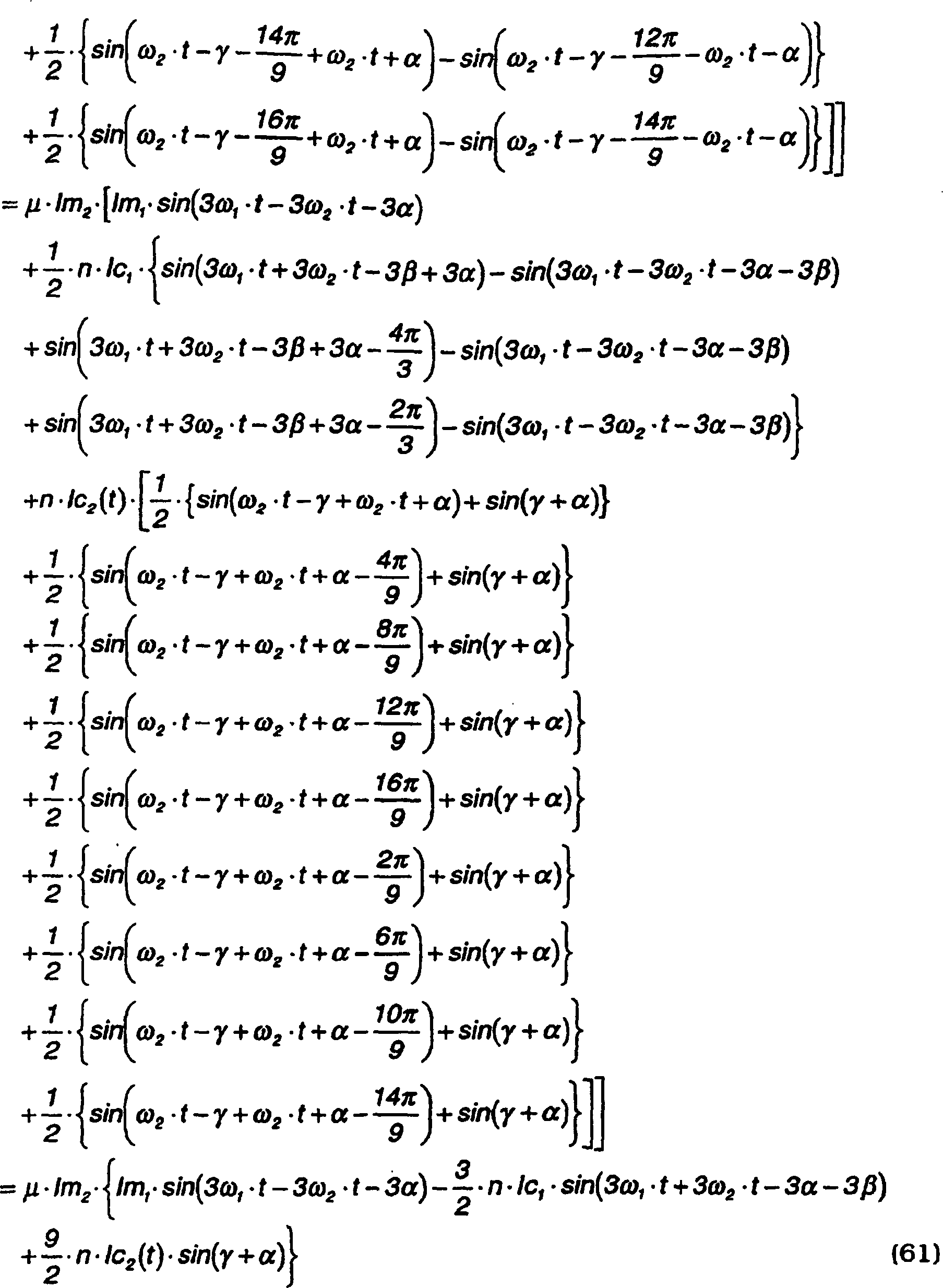
(3-5-3) Zusammenfassung(3-5-3) Summary
Wie in dem Falle von Gleichung (48) beschrieben, heben sich, wie in dem Falle des Drei-Phasen-Wechselstroms die ersten und zweiten Terme auf der rechten Seite der Gleichung (61) auf, wenn diese Terme in anderen Phasen berücksichtigt werden.As in the case of equation (48) described, as in the case of the three-phase alternating current the first and second terms on the right side of the equation (61) if these terms are taken into account in other phases.
Wenn diese Gleichung (61) für den Fall, in welchem die inneren rotierenden magnetischen Felder durch einen Neun-Phasen-Wechselstrom erzeugt werden, mit der vorstehend erwähnten Gleichung (52) verglichen wird, in welcher die inneren rotierenden magnetischen Felder durch einen Drei-Phasen-Wechselstrom erzeugt werden, ist der feste Term der Gleichung (61), d. h., der letzte Term das Dreifache von dem der Gleichung (52).If this equation (61) for the case in which the internal rotating magnetic fields by a Nine-phase alternating current can be generated using the equation mentioned above (52) is compared, in which the inner rotating magnetic Fields are generated by a three-phase alternating current the fixed term of equation (61), d. that is, the last term is threefold from that of equation (52).
Mit anderen Worten, wenn der Treiberstrom der inneren Magnete m2 ein Neun-Phasen-Wechselstrom (Ii–Iix) ist, wird eine Antriebkraft, d. h., ein Antriebsdrehmoment zu dem Dreifachen von dem, wenn der Treiberstrom der inneren Magnete ein Drei-Phasen-Wechselstrom ist.In other words, when the driving current of the inner magnets m 2 is a nine-phase alternating current (Ii-Iix), a driving force, that is, a driving torque becomes three times that when the driving current of the inner magnets is a three-phase AC is.
Mit anderen Worten, der zum Erzeugen desselben Antriebsdrehmomentes erforderliche Treiberstrom für die inneren Magnete m2 ist nur ein Drittel.In other words, the driving current required for generating the same drive torque for the inner magnets m 2 is only a third.
Dieses schließt die theoretische Analyse dieser Erfindung ab.This concludes the theoretical analysis this invention.
Anschliessend werden fünfte bis
elfte Ausführungsformen
dieser Erfindung unter Bezugnahme auf
In diesem Ausführungsformen ist der Aussenrotor
Wie es aus diesen Ausführungsformen ersichtlich ist, ist diese Erfindung nicht auf den Fall beschränkt, in welchem die Anzahl der magnetischen Pole der Aussenmagnete m1 grösser als die Anzahl der magnetischen Pole der Innenmagnete m2 und kann auch auf den Fall angewendet werden, in welchem die Anzahl der magnetischen Pole der Aussenmagnete m1 kleiner als die Anzahl der magnetischen Pole der Innenmagnet m2 ist.As can be seen from these embodiments, this invention is not limited to the case in which the number of magnetic poles of the outer magnets m 1 is greater than the number of magnetic poles of the inner magnets m 2 and can also be applied to the case in which the number of magnetic poles of the outer magnets m 1 is smaller than the number of magnetic poles of the inner magnets m 2 .
Es ist jedoch einfach, eine Drehmomentfluktuation zu vermeiden, indem das Magnetpol-Anzahlverhältnis der zwei Rotoren auf eine gerade Anzahl anstelle einer ungeraden Anzahl eingestellt wird.However, torque fluctuation is easy to avoid by changing the magnetic pole number ratio of the two rotors an even number is set instead of an odd number.
Anschliessend wird eine zwölfte Ausführungsform
dieser Erfindung unter Bezugnahme auf
In dieser Ausführungsform sind ein Zwischenrotor
Auf diese Weise können die zwei Rotoren
Jedoch ist in diesem Falle kein Eisenrahmen
zwischen dem Rotor
Ferner können die zwei Rotoren auch ausserhalb des Stators angeordnet sein. Wenn der Stator in der äussersten oder innersten Position angeordnet ist, wird die Kühlung der Statorspulen erleichtert.Furthermore, the two rotors can also be arranged outside the stator. If the stator is in the extreme or innermost position, the cooling of the Stator coils relieved.
In den vorstehend erwähnten Ausführungsformen werden die magnetischen Pole des Rotors durch Magnete erzeugt, wobei jedoch auch anstelle der Permanentmagnete Solenoide (Elektromagnete) verwendet werden könnten.In the above-mentioned embodiments the magnetic poles of the rotor are generated by magnets, whereby but instead of permanent magnets, solenoids (electromagnets) could be used.
Auch das von der Regelschaltung
Diese Erfindung ist nicht auf einen Radialspalt-Motor/Generator beschränkt, in welchem der Spalt zwischen dem Rotor und dem Stator in radialer Richtung festgelegt ist, und kann auch auf einem Motor/Generator angewendet werden, im welchem der Spalt zwischen dem Rotor und dem Stator sich in einer axialen Richtung befindet.This invention is not in one Radial gap motor / generator limited in which the gap between the rotor and the stator is fixed in the radial direction, and can also be used on a motor / generator in which the gap between the rotor and the stator is in an axial Direction.
In der Beschreibung der vorstehenden Ausführungsformen wurde der Fall beschrieben, in welchem die Rotoren als ein Motor betrieben wurden, wobei diese jedoch natürlich auch als Generatoren eingesetzt werden können, oder ein Rotor als ein Motor und der andere als ein Generator zum Erzeugen von Energie eingesetzt werden kann.In the description of the above embodiments the case was described in which the rotors as a motor were operated, but of course also as generators can be used or one rotor as a motor and the other as a generator for Generation of energy can be used.
Schliesslich wird eine dreizehnte
Ausführungsform
der Erfindung unter Bezugnahme auf die
In dieser Ausführungsform sind gemäss Darstellung
in
Die Induktionsspulen
Der Stator
Der Aufbau des Inverters
In dieser Ausführungsform erzeugt die Regelschaltung
Anschliessend wird ein Verfahren
für die
Festlegung der Ströme
beschrieben, welche durch die Spulen
Es wird angenommen, dass vier Sätze von
Spulen A, B, C die rotierende magnetische Felder im Bezug auf den
Aussenrotor
Zur Vereinfachen der Relationen zwischen
dem Stator und den Spulen unterschiedlicher Phase in den Rotoren
werden die Spulen
In
Auf diese Weise erzeugt ein durch
die Aussenspulen A, C, B fliessender Drei-Phasen-Wechselstrom rotierende magnetische
Felder bezüglich
der Induktionsspulen a, b, c des Aussenrotors
In diesem Falle ist die Anzahl der
magnetischen Pole des Aussenrotors zwölf, die Anzahl der magnetischen
Pole des Innenrotors
Anschliessend wird der Fall betrachtet,
in welchem die benachbarten Spulen A und U, B und W, C und V, A
und U, D und W, C und V in
Die Ströme, welche durch die Spulen
#1 bis #12 durchgeleitet werden sollen, sind wie folgt.
I1 = IA + IU
I2 = IC
I3 =
IB + IW
I4 = IA
I5 =
IC + IV
I6 = IB
I7 = IA
+ IU
I8 = IC
I9 =
IB + IW
I10 = IA
I11 = IC
+ IV
I12 = IB The currents to be passed through the coils # 1 to # 12 are as follows.
I 1 = IA + IU
I 2 = IC
I 3 = IB + IW
I 4 = IA
I 5 = IC + IV
I 6 = IB
I 7 = IA + IU
I 8 = IC
I 9 = IB + IW
I 10 = IA
I 11 = IC + IV
I 12 = IB
In diesem Falle ist die Belastung der Spulen, durch welche die Ströme I1, I3, I5, I7, I9, I11 geleitet werden, grösser als die der restlichen Spulen, durch welche die Ströme I2, I4, I6, I8, I10, I12 geleitet werden. Daher wird eine getrennte Stromfestlegung, in welcher die Belastung über den Rest der Spulenverteilung in Betracht gezogen.In this case, the load on the coils through which the currents I 1 , I 3 , I 5 , I 7 , I 9 , I 11 are conducted is greater than that of the remaining coils through which the currents I 2 , I 4 , I 6 , I 8 , I 10 , I 12 are passed. Therefore a separate current setting is considered, in which the load over the rest of the coil distribution is considered.
Beispielsweise sind beim Vergleich
von
In diesem Falle ist die Spule U etwas in der Richtung im Uhrzeigersinn der Figur verschoben. Die verschobene Spule wird als eine Spule U' bezeichnet.In this case the coil U is something shifted in the clockwise direction of the figure. The postponed Coil is referred to as a coil U '.
Die Hälfte eines durch die Spule U' fliessenden Stroms IU' ist jeder von den Spulen A und C zugeordnet. Ein ähnliches Vorgehen wird für die anderen Spulen durchgeführt.Half one through the spool U 'flowing current IU 'is everyone of assigned to coils A and C. A similar approach is used for the others Coils performed.
Somit sind die nachstehenden Festlegungen des zusammengesetzten Stroms möglich.So the following are determinations of the composite stream possible.

Die nachstehenden Festlegungen des
zusammengesetzten Stroms sind ebenfalls möglich.
I1 =
IA + Ii
I2 = IC + Iii
I3 =
IB+Iiii
I4 = IA + Iiv
I5 =
IC + Iv
I6 = IB + Ivi
I7 =
IA + Ivii
I8 = IC + Iviii
I9 =
IB + Iix
I10 = IA + Ix
I11 =
IC + Ixi
I12 = IB + IxiiThe following stipulations of the composite current are also possible.
I 1 = IA + Ii
I 2 = IC + Iii
I 3 = IB + Iiii
I 4 = IA + Iiv
I 5 = IC + Iv
I 6 = IB + Ivi
I 7 = IA + Ivii
I 8 = IC + Iviii
I 9 = IB + Iix
I 10 = IA + Ix
I 11 = IC + Ixi
I 12 = IB + Ixii
Hier ist Ii–Ixii des zweiten Terms auf
der rechten Seite der Gleichungen ein Zwölf-Phasen-Wechselstrom gemäss Darstellung
in
Wenn der zusammengesetzte Strom auf
diese Weise festgelegt ist, werden zwei rotierende magnetische Felder,
d. h., innere rotierende magnetische Felder und ein äusseres
rotierende magnetisches Feld gleichzeitig erzeugt, aber ein Rotationsdrehmoment
aufgrund des äusseren
rotierenden magnetischen Feldes wirkt nicht auf die Induktionsspulen
Zuerst wird unter Bezugnahme auf
Dies entspricht dem Fall, in welchem
die Permanentmagnete des Rotors
Hier ist, wenn die Frequenz des Drei-Phasen-Wechselstrom
für den
Antrieb des Aussenrotors als fr1, und die
Frequenz des Drei-Phasen-Wechselstroms für den Antrieb des Innenrotors
Jedoch tritt, wenn ein Generator/Motor, der Induktionsspulen in den Rotoren verwendet, als ein Motor betrieben wird, eine Abweichung zwischen der Rotationsgeschwindigkeit der rotierenden magnetischen Felder und der Rotationsgeschwindigkeit der Induktionsspule, d. h., der Rotationsgeschwindigkeit des Rotors auf. Das Verhältnis dieser zwei wird direkt hierin nachstehend als ein Schlupffaktor bezeichnet.However, when a generator / motor using induction coils in the rotors occurs as a motor is operated, a deviation between the rotational speed of the rotating magnetic fields and the rotational speed of the induction coil, that is, the rotational speed of the rotor. The ratio of these two is referred to hereinafter as a slip factor.
Daher wird, wenn der Schlupffaktor
des Aussenrotors
Ferner wird, wenn der Schlupffaktor
des Innenrotors
(4) Auswirkung von rotierenden magnetischen Feldern auf einen Rotor bei einer Rotation des anderen Rotors(4) Impact of rotating magnetic fields on one rotor as the other rotates rotor
(4-1) Rotierendes magnetisches Feld(4-1) Rotating magnetic field
Wenn ein Drei-Phasen-Wechselstrom
in die Innenspulen U, V, W des Stators
In ähnlicher Weise werden, wenn
ein Drei-Phasen-Wechselstrom in die Innenspulen A, C, B des Stators
Die Zeit t in den vorstehenden Gleichungen
ist so definiert, dass t = 0 den Moment bezeichnet, in welchem die
Induktionsspule a in dem Aussenrotor
(4-2) Auswirkung von inneren rotierenden magnetischen Feldern auf die Rotation des Aussenrotors(4-2) Impact of internal rotating magnetic fields on the rotation of the outer rotor
Wenn die vier Induktionsspulen a,
vier Induktionsspulen b und vier Induktionsspulen c des Aussenrotors

Durch Einsetzen der Gleichung (62) in die Gleichungen (64), (65), (66) werden die nachstehenden Gleichungen (67), (68), (69) erhalten.By inserting equation (62) into equations (64), (65), (66) the following equations (67), (68), (69) obtained.

Die vorstehenden Gleichungen können umgeschrieben werden wie folgt.The above equations can be rewritten are as follows.

Daher wirkt der Strom, welcher die
inneren rotierenden magnetischen Felder erzeugt, nicht auf die Induktionsspule
(4-3) Auswirkung von äusseren rotierenden magnetischen Feldern auf die Rotation des Innenrotors.(4-3) Impact of exterior rotating magnetic fields on the rotation of the inner rotor.
Wenn die zwei Induktionsspulen u
zwei Induktionsspulen w und zwei Induktionsspulen v des Innenrotors 
Durch Einsetzen der Gleichung (63) in die Gleichungen (70), (71), (72) werden die nachstehenden Gleichungen (74), (75), (76) erhalten.By inserting equation (63) into equations (70), (71), (72) are the following equations (74), (75), (76) obtained.

Die Gleichungen (74), (75), (76) können wie folgt umgeschrieben werden.Equations (74), (75), (76) can can be rewritten as follows.

Daher wirken die Ströme, welche
die rotierenden magnetischen Felder erzeugen, nicht auf die Induktionsspule
(4-4) Zusammenfassung(4-4) Summary
Die Ströme, welche den Innenrotor antreiben,
haben keine Auswirkung auf die Rotation des Aussenrotors
(5) Berechnung der Antriebskraft des Aussenrotors(5) Calculation of the driving force of the outer rotor
Die Antriebskraft des Aussenrotors
(5-1) In die Induktionsspule des Aussenrotors induzierte Spannung(5-1) In the induction coil of the external rotor induced voltage
Wenn die vier Induktionsspulen a,
vier Induktionsspulen b und vier Induktionsspulen c des Aussenrotors

Durch Einsetzen der Gleichung (63) in die Gleichungen (77), (78), (79) werden die nachstehenden Gleichungen (80), (81), (82) erhalten.By inserting equation (63) into equations (77), (78), (79) are the following equations (80), (81), (82) obtained.


(5-2) In die Induktionsspulen des Aussenrotors fliessender Strom(5-2) In the induction coils current flowing in the outer rotor
Wenn eine Last der Impedanz Z1 auf die Induktionsspulen a, b, c wirkt,
besitzen die Ströme
Ia, Ib, Ic, die in die Induktionsspulen a, b, c des Aussenrotors 
Ein Wert der Impedanz Z1 ist
so festgelegt, dass er eine ausreichende Grösse dergestalt besitzt, dass die
Amplitude Bm1 des durch die Aussenspulen
A, B, C des Stators
(5-3) Durch Induktionsspulen des Aussenrotoren erfahrenes magnetisches Feld(5-3) By induction coils of the external rotor experienced magnetic field
Die magnetischen Felder Ba(t), Bb(t),
Bc(t), die durch die Induktionsspulen a, b, c des Aussenrotors

Aus den Gleichungen (83), (84), (85)
und den Gleichungen (86), (87), (88) werden Kräfte fa, fb, fc, welchen die
Induktionsspulen a, b, c des Aussenrotors

Wenn die vorstehenden Gleichungen
unter Verwendung der Formel ![]()
![]()


(5-4) Antriebskraft des Aussenrotors(5-4) Driving force of the outer rotor
Die Antriebskraft des Aussenrotors

(5-5) Zusammenfassung(5-5) Summary
Gemäss Gleichung (92) kann die
Antriebskraft des Aussenrotors
(6) Berechnung der Antriebskraft des Innenrotors(6) Calculation of the driving force of the inner rotor
Diese Analyse ist ähnlich der
Berechnung der Antriebskraft des Innenrotors im vorstehenden Absatz (
(6-1) In Induktionsspulen des Innenrotors induzierte Spannung.(6-1) In induction coils of the inner rotor induced voltage.
Wenn die zwei Induktionsspulen u, zwei Induktionsspulen w und zwei Induktionsspulen v des Innenrotors jeweils in Reihe geschaltet werden, sind die Spannungen Eu, Ev, Ew, die in die Induktionsspulen u, v, w induziert werden durch die nachstehenden Gleichungen (93), (94), (95) gegeben.If the two induction coils u, two induction coils w and two induction coils v of the inner rotor are connected in series, the voltages Eu, Ev, Ew, which are induced in the induction coils u, v, w by the Equations (93), (94), (95) below.

Durch Einsetzen der Gleichung (62) in die Gleichungen (93, (94), (95) werden die nachstehenden Gleichungen (96), (97), (98) erhalten.By inserting equation (62) into equations (93, (94), (95) the following equations (96), (97), (98) obtained.

(6-2) In Induktionsspulen des Innenrotors fliessender Strom.(6-2) In induction coils current flowing in the inner rotor.
Wenn eine Lasterimpedanz Z2 auf die Induktionsspulen u, v, w wirkt,
besitzen die in den Induktionsspulen u, v, w des Innenrotors 
Ein Wert der Impedanz Z2 wird
so bestimmt, dass eine ausreichende Grösse dergestalt besitzt, dass die
Amplitude Bm2 des durch die Innenspulen
U, V, W des Stators
(6-3) Durch Induktionsspulen des Innenrotors erfahrenes magnetisches Feld(6-3) By induction coils experienced magnetic field of the inner rotor
Die durch die Induktionsspulen u,
v, w des Innenrotors

Aus den Gleichungen (99), (100), (101) und Gleichungen (102), (103), (104) können Kräfte fu, fv, fw, welche das magnetische Feld auf den durch die Induktionsspulen des Innenrotors fliessenden Strom ausübt, wie folgt ausgedrückt werden.From equations (99), (100), (101) and equations (102), (103), (104) can force fu, fv, fw, which the magnetic field on the through the induction coils of the inner rotor flowing current, like follows expressed become.

Durch Umschreibung der vorstehenden
Gleichung unter Verwendung der Formel ... ![]()
![]()

(6-4) Antriebskraft des Innenrotors(6-4) Driving force of the inner rotor
Die Antriebskraft des Innenrotors

(6-5) Zusammenfassung(6-5) Summary
Der durch die Aussenspulen A, C,
B des Stators
Daher tritt eine Phasendifferenz
n zwischen A-a, B-b, C-c gemäss
der Impedanz Z2 wie in einem gewöhnlichen
Induktionsmotor auf, und demzufolge wirkt eine Antriebskraft auf
den Aussenrotor
In ähnlicher Weise wirkt ein durch
die Innenspulen U, V, W des Stators
Daher tritt eine Phasendifferenz γ zwischen
U-u, V-v, W-v gemäss
der Impedanz Z2, und demzufolge wirkt eine
Antriebskraft auf den Innenrotor
Diese Tatsache zeigt, dass auch in
dem Falle, in welchem das Magnetpol-Anzahlverhältnis 2 : 1 ist, die zwei Rotoren
Wie es in den Ausführungsformen eines Permanentmagnete verwendenden Motors/Generators beschrieben ist, ist die Situation, in welcher die Ströme für den Betrieb eines Rotors die Rotation des anderen Rotors nicht beeinträchtigen, nicht auf den Fall beschränkt, in welchem das Magnetpol-Anzahlverhältnis der zwei Rotoren 2 : 1 ist, sondern ist ebenfalls ein gemeinsames Merkmal, wenn das Magnetpol-Anzahlverhältnis eine geradzahlige Zahl statt einer ungeradzahligen Zahl ist.As is the case with the embodiments of a motor / generator using permanent magnets is the situation in which the currents for the operation of a rotor do not interfere with the rotation of the other rotor, not on the case limited, in which the magnetic pole number ratio of the two rotors 2: 1, but is also a common feature when the magnetic pole number ratio is one is an even number instead of an odd number.
Ausserdem kann, wenn das Magnetpol-Anzahlverhältnis eine
gerade Zahl statt einer ungeraden Zahl ist, und insbesondere wenn
die gerade Zahl
Beispielsweise ist, da zwei Spulen
für eine
Polanzahl von 2 erforderlich sind, und das Dreifache dieser Anzahl
von Spulen für
die Durchführung
eines Drei-Phasen-Wechselstroms
erforderlich ist, die Gesamtanzahl der Innenrotorspulen 2 × 3 = 6.
Ebenso ist die Gesamtanzahl der Aussenrotorspulen
Ausser Fällen, in welchem das Polanzahlverhältnis 2
: 1 ist, überschreitet
jedoch die minimale Anzahl der gesamten Spulen für beide Rotoren
Wie es in den Ausführungsformen eines Permanentmagnete verwendenden Motors/Generators beschrieben wurde, kann das Magnetpol/Anzahlverhältnis eine gerade Anzahl statt einer ungeraden Anzahl oder eine ungerade Anzahl statt einer geraden Anzahl sein.As is the case with the embodiments of a motor / generator using permanent magnets the magnetic pole / number ratio can take an even number an odd number or an odd number instead of an even number Number.
In diesem Falle bewirken die Treiberströme für den einen Rotor eine Fluktuation in dem Rotationsdrehmoment des anderen Rotors, wobei diese Fluktuation durch ein Verfahren, wie z. B. die vorgenannte Amplitudenmodulation, eliminiert werden kann.In this case, the driver currents cause one Rotor a fluctuation in the rotational torque of the other rotor, this fluctuation by a method such. B. the aforementioned Amplitude modulation can be eliminated.
Obwohl die Erfindung vorstehend unter Bezugnahme auf bestimmte Ausführungsformen der Erfindung beschrieben wurde, ist die Erfindung nicht auf die vorstehend beschriebenen Ausführungsformen beschränkt. Modifikationen und Variationen der vorstehend beschriebenen Ausführungsformen werden für den Fachmann auf diesem Gebiet im Licht der vorstehenden Lehren offensichtlich sein.Although the invention is described above under Reference to certain embodiments the invention has been described, the invention is not limited to Embodiments described above limited. Modifications and variations of the above-described embodiments be for those skilled in the art in light of the above teachings be obvious.
Beispielsweise waren in dieser Ausführungsform beide Rotoren mit Induktionsspulen versehen, und in den ersten bis 13. Ausführungsformen waren beide Rotoren mit Permanentmagneten versehen, wobei jedoch die magnetischen Pole des einen Rotors Induktionsspulen umfassen können und die magnetischen Pole des anderen Rotors Permanentmagnete umfassen können.For example, in this embodiment both rotors with induction coils, and in the first to 13. Embodiments Both rotors were provided with permanent magnets, but the magnetic poles of a rotor can include induction coils and the magnetic poles of the other rotor comprise permanent magnets can.
Die Ausführungsformen dieser Erfindung, in welchen ein exklusives Eigentum oder Privileg beansprucht wird, sind wie folgt definiert:The embodiments of this invention in which an exclusive property or privilege is claimed, are defined as follows:
Claims (12)
Applications Claiming Priority (8)
| Application Number | Priority Date | Filing Date | Title |
|---|---|---|---|
| JP07747898A JP3480302B2 (en) | 1998-03-25 | 1998-03-25 | Rotating electric machine |
| JP07744998A JP3480300B2 (en) | 1998-03-25 | 1998-03-25 | Rotating electric machine |
| JP7750898 | 1998-03-25 | ||
| JP7744998 | 1998-03-25 | ||
| JP7750898 | 1998-03-25 | ||
| JP7747898 | 1998-03-25 | ||
| JP16238098A JP3480315B2 (en) | 1998-06-10 | 1998-06-10 | Rotating electric machine |
| JP16238098 | 1998-06-10 |
Publications (2)
| Publication Number | Publication Date |
|---|---|
| DE69912504D1 DE69912504D1 (en) | 2003-12-11 |
| DE69912504T2 true DE69912504T2 (en) | 2004-05-06 |
Family
ID=27466070
Family Applications (1)
| Application Number | Title | Priority Date | Filing Date |
|---|---|---|---|
| DE69912504T Expired - Lifetime DE69912504T2 (en) | 1998-03-25 | 1999-03-24 | Motor / generator |
Country Status (3)
| Country | Link |
|---|---|
| US (1) | US6049152A (en) |
| EP (1) | EP0945963B1 (en) |
| DE (1) | DE69912504T2 (en) |
Cited By (1)
| Publication number | Priority date | Publication date | Assignee | Title |
|---|---|---|---|---|
| US10164494B2 (en) | 2014-03-26 | 2018-12-25 | Feaam Gmbh | Electric machine |
Families Citing this family (69)
| Publication number | Priority date | Publication date | Assignee | Title |
|---|---|---|---|---|
| US6570361B1 (en) * | 1999-02-22 | 2003-05-27 | Borealis Technical Limited | Rotating induction apparatus |
| US6864661B2 (en) * | 1999-02-22 | 2005-03-08 | Borealis Technical Limited | Rotating induction apparatus |
| US6922037B2 (en) * | 1999-02-22 | 2005-07-26 | Borealis Technical Limited | Rotating induction apparatus |
| US6252324B1 (en) * | 1999-04-22 | 2001-06-26 | Borealis Technical Limited | Method of winding a rotating induction apparatus |
| US6348775B1 (en) * | 1999-05-11 | 2002-02-19 | Borealis Technical Limited | Drive wave form synchronization for induction motors |
| JP3480439B2 (en) | 1999-09-27 | 2003-12-22 | 日産自動車株式会社 | Control device for rotating electric machine |
| JP3454234B2 (en) | 1999-09-27 | 2003-10-06 | 日産自動車株式会社 | Split core motor |
| US6639337B1 (en) | 1999-09-27 | 2003-10-28 | Nissan Motor Co., Ltd. | Motor/generator with multiple rotors |
| EP1089425B1 (en) * | 1999-09-28 | 2008-07-30 | Nissan Motor Co., Ltd. | Motor/generator with multiple rotors |
| JP3496595B2 (en) | 1999-10-27 | 2004-02-16 | 日産自動車株式会社 | Rotating electric machine |
| JP2001157487A (en) * | 1999-11-26 | 2001-06-08 | Nissan Motor Co Ltd | Controller for electric rotating machine |
| JP3671836B2 (en) | 1999-12-10 | 2005-07-13 | 日産自動車株式会社 | Compound motor |
| US6291963B2 (en) | 1999-12-15 | 2001-09-18 | Nissan Motor Co., Ltd. | Drive circuit for motor/generator |
| JP3719136B2 (en) * | 2000-01-17 | 2005-11-24 | 日産自動車株式会社 | Rotating electric machine and drive system |
| US6304017B1 (en) * | 2000-02-18 | 2001-10-16 | The United States Of America As Represented By The Secretary Of The Army | Counter rotating nested cylinders in electrical machinery |
| JP2001298920A (en) * | 2000-04-18 | 2001-10-26 | Tamagawa Seiki Co Ltd | Two-shaft concentric motor |
| US6472845B2 (en) | 2000-08-07 | 2002-10-29 | Nissan Motor Co., Ltd. | Motor/generator device |
| JP4269544B2 (en) * | 2000-09-14 | 2009-05-27 | 株式会社デンソー | Multi-rotor synchronous machine |
| JP3551164B2 (en) * | 2001-07-09 | 2004-08-04 | 日産自動車株式会社 | Current detection device for rotating electrical machines |
| JP3578451B2 (en) | 2001-07-23 | 2004-10-20 | 日産自動車株式会社 | Drive |
| JP3671884B2 (en) | 2001-08-30 | 2005-07-13 | 日産自動車株式会社 | Rotating electric machine |
| JP3671910B2 (en) * | 2002-01-16 | 2005-07-13 | 日産自動車株式会社 | Connection method of rotating electric machine |
| JP3690355B2 (en) | 2002-02-12 | 2005-08-31 | 日産自動車株式会社 | Stator support structure for rotating electrical machines |
| JP2003244992A (en) | 2002-02-21 | 2003-08-29 | Nissan Motor Co Ltd | Current control method for rotating electric machine |
| JP3711956B2 (en) * | 2002-04-01 | 2005-11-02 | 日産自動車株式会社 | Driving method of rotating electric machine |
| JP3716809B2 (en) * | 2002-04-01 | 2005-11-16 | 日産自動車株式会社 | Rotating electric machine |
| CN1515061B (en) * | 2002-04-01 | 2010-04-28 | 日产自动车株式会社 | Cooling structure of multi-shaft multi-layer rotary electric machine |
| JP3757890B2 (en) * | 2002-04-01 | 2006-03-22 | 日産自動車株式会社 | Driving method of rotating electric machine |
| JP3711955B2 (en) * | 2002-04-01 | 2005-11-02 | 日産自動車株式会社 | Control device for rotating electrical machine |
| JP3719244B2 (en) * | 2002-12-18 | 2005-11-24 | 日産自動車株式会社 | Coaxial multiple position detector and rotating electric machine using the same |
| FR2861227B1 (en) * | 2003-10-21 | 2007-07-13 | Renault Sa | ELECTRIC MECHANICAL POWER TRANSMISSION, IN PARTICULAR FOR A MOTOR VEHICLE TRANSMISSION |
| US20060236715A1 (en) * | 2003-12-09 | 2006-10-26 | Isao Nikai | Air conditioning system |
| DE102004019465B4 (en) * | 2004-04-15 | 2014-01-23 | Keiper Gmbh & Co. Kg | Drive unit for a vehicle seat |
| DE102004019469A1 (en) * | 2004-04-15 | 2005-11-10 | Keiper Gmbh & Co.Kg | Drive unit in a vehicle |
| DE102004019471B4 (en) * | 2004-04-15 | 2014-01-02 | Keiper Gmbh & Co. Kg | Drive unit for a vehicle seat |
| DE102004019466B4 (en) * | 2004-04-15 | 2006-07-13 | Keiper Gmbh & Co.Kg | Adjustment device for a vehicle seat |
| DE102004019463A1 (en) * | 2004-04-15 | 2005-11-10 | Keiper Gmbh & Co.Kg | Drive unit for a vehicle seat |
| JP5141030B2 (en) | 2006-02-14 | 2013-02-13 | 日産自動車株式会社 | Rotating electric machine |
| JP4620024B2 (en) * | 2006-03-06 | 2011-01-26 | 本田技研工業株式会社 | Electric motor |
| US7683520B2 (en) * | 2006-03-06 | 2010-03-23 | Honda Motor Co., Ltd. | Electric motor and rotating device that changes relative phase of rotors |
| JP5205594B2 (en) * | 2006-03-16 | 2013-06-05 | 日産自動車株式会社 | Rotating electric machine |
| JP4754378B2 (en) * | 2006-03-22 | 2011-08-24 | 本田技研工業株式会社 | Electric motor control device |
| GB2437568B (en) | 2006-04-24 | 2009-02-11 | Univ Sheffield | Electrical machines |
| EP1860754A1 (en) * | 2006-05-24 | 2007-11-28 | HONDA MOTOR CO., Ltd. | Electric motor |
| JP4184392B2 (en) * | 2006-06-27 | 2008-11-19 | 本田技研工業株式会社 | Electric motor |
| DE102006062613A1 (en) * | 2006-12-29 | 2008-07-03 | Thoms, Michael, Dr. | Permanent magnet machine e.g. synchronous motor, for e.g. separating air/liquid/solid mixtures, has rotor sided permanent magnets with number of poles for each number of revolution, and stator-sided armature windings extending over rotors |
| FR2915523A1 (en) * | 2007-04-27 | 2008-10-31 | Snecma Sa | DEVICE FOR GENERATING ELECTRIC ENERGY IN A DOUBLE-BODY GAS TURBINE ENGINE |
| US7999432B2 (en) * | 2007-08-17 | 2011-08-16 | Kura Laboratory Corporation | Field controllable rotating electric machine system with magnetic excitation part |
| RU2351793C1 (en) * | 2007-10-04 | 2009-04-10 | Виктор Михайлович Лятхер | Wave-flow power installation |
| JP2009090882A (en) * | 2007-10-10 | 2009-04-30 | Honda Motor Co Ltd | Hybrid vehicle |
| NO329244B1 (en) * | 2008-12-19 | 2010-09-20 | Smart Motor As | Method for operating a permanently magnetized synchronous machine as well as a device at an electrical plant comprising such a machine |
| ITBO20090075A1 (en) * | 2009-02-13 | 2010-08-14 | Magneti Marelli Spa | ELECTRIC MACHINE WITH SINGLE STATOR AND TWO ROTORS BETWEEN THEM INDEPENDENT AND ROAD VEHICLE PROVIDED WITH THIS ELECTRIC MACHINE |
| TR200904571A1 (en) * | 2009-06-11 | 2011-01-21 | Karaoğlan Kemal | Vehicle wheel with generator and electric motor. |
| US8258737B2 (en) * | 2009-06-24 | 2012-09-04 | Casey John R | Electric machine with non-coaxial rotors |
| WO2014046348A1 (en) * | 2012-09-20 | 2014-03-27 | Sun Sang-Kyu | Power generator |
| JP6093592B2 (en) * | 2013-02-22 | 2017-03-08 | 株式会社Ihi | Magnetic wave gear device |
| US9973066B2 (en) | 2013-05-17 | 2018-05-15 | Tidnab Innovations Inc. | Multi-layer sandwich-shaped electric wheel |
| WO2015040592A2 (en) * | 2013-09-20 | 2015-03-26 | Makgeru Kabu Walter | Electric motor and electric generator |
| US10523074B2 (en) | 2014-01-16 | 2019-12-31 | Maestra Energy, Llc | Electrical energy conversion system in the form of an induction motor or generator with variable coil winding patterns exhibiting multiple and differently gauged wires according to varying braid patterns |
| US9906105B1 (en) | 2014-01-28 | 2018-02-27 | Maestra Energy, Llc | Electrical induction motor with reconfigured rotor mounted commutators for receiving an armature current from a stator mounted brush component along with a reversing gear arrangement for driving a pair of opposite gear rings |
| US9906106B1 (en) | 2014-01-31 | 2018-02-27 | Maestra Energy, Llc | Electrical generator or motor with variable coil winding patterns exhibiting multiple wires incorporated into a plurality coil configurations defined around a rotor and incorporating a gearbox arrangement exhibiting oppositely driven rotor and stator gears configured with multi-tiered reversing gears exhibiting both straight and helical patterns and for varying turning ratios for establishing either of acceleration or deceleration aspects for increased power output |
| US9825514B1 (en) | 2014-02-05 | 2017-11-21 | Maestra Energy, Llc | Electrical generator or motor with variable coil winding patterns exhibiting multiple wires incorporated into a plurality of independent three stage coil configurations and incorporating a belt drive arrangement exhibiting first and second rotating pully wheels in combination with opposite belt rotating magnet and coil supporting components for providing increased power output |
| EP3007336B1 (en) | 2014-10-07 | 2016-11-30 | C.R.F. Società Consortile per Azioni | Synchronous electric machine with two rotors |
| CN104600898B (en) * | 2015-01-19 | 2018-03-23 | 安徽美芝制冷设备有限公司 | Plug-assembly and there is its motor and compressor |
| JP6820090B2 (en) | 2015-07-21 | 2021-01-27 | 三星電子株式会社Samsung Electronics Co.,Ltd. | Washing machine and its motor |
| US10295376B2 (en) * | 2015-09-18 | 2019-05-21 | Honeywell International Inc. | Multi-turn angle position sensor (extendible for more than 10 turns) |
| US10574123B2 (en) * | 2015-12-17 | 2020-02-25 | Hamilton Sundstrand Corporation | Concentric dual rotor electric machine |
| DE102016117911A1 (en) | 2016-09-22 | 2018-03-22 | Volabo Gmbh | Electric machine |
| CN109617349B (en) * | 2018-11-28 | 2020-02-21 | 华中科技大学 | Single-winding double-mechanical-port permanent magnet motor |
Family Cites Families (17)
| Publication number | Priority date | Publication date | Assignee | Title |
|---|---|---|---|---|
| US396355A (en) * | 1889-01-15 | Dynamo-electri | ||
| US2666174A (en) * | 1951-02-08 | 1954-01-12 | Joseph M Pestarini | Synchronous motor |
| US4087698A (en) * | 1977-04-22 | 1978-05-02 | Franklin W. Baumgartner | Alternating current power generating system |
| US4407132A (en) * | 1980-02-20 | 1983-10-04 | Daihatsu Motor Co., Ltd. | Control apparatus and method for engine/electric hybrid vehicle |
| US4453447A (en) * | 1982-09-30 | 1984-06-12 | Shinneman Leonice L | Percussion instruments bow |
| DE3444420A1 (en) * | 1984-12-04 | 1986-06-05 | Arnold 7312 Kirchheim Müller | Device for producing pivoting movements |
| US4866321A (en) * | 1985-03-26 | 1989-09-12 | William C. Lamb | Brushless electrical machine for use as motor or generator |
| US4644207A (en) * | 1985-04-15 | 1987-02-17 | Rockwell International Corporation | Integrated dual pump system |
| MX161230A (en) * | 1985-12-23 | 1990-08-24 | Unique Mobility Inc | IMPROVEMENTS IN LIGHTWEIGHT ELECTROMAGNETIC TRANSDUCER |
| US5184040A (en) * | 1989-09-04 | 1993-02-02 | Lim Jong H | Electric power generators having like numbers of magnets and coils |
| US5594322A (en) * | 1993-05-12 | 1997-01-14 | Sundstrand Corporation | Starter/generator system with variable-frequency exciter control |
| US5396140A (en) * | 1993-05-28 | 1995-03-07 | Satcon Technology, Corp. | Parallel air gap serial flux A.C. electrical machine |
| US5744895A (en) * | 1995-01-31 | 1998-04-28 | Nippondenso Co., Ltd. | System for driving electric vehicles |
| EP0725474B1 (en) * | 1995-01-31 | 2001-11-14 | Denso Corporation | System and method for driving electric vehicle |
| JP3052786B2 (en) * | 1995-06-09 | 2000-06-19 | 株式会社デンソー | Vehicle drive device and drive control method thereof |
| US5783894A (en) * | 1995-10-31 | 1998-07-21 | Wither; Thomas A. | Method and apparatus for generating electrical energy |
| US5793136A (en) * | 1996-06-05 | 1998-08-11 | Redzic; Sabid | Differential motor/generator apparatus |
-
1999
- 1999-03-24 EP EP99105953A patent/EP0945963B1/en not_active Expired - Lifetime
- 1999-03-24 DE DE69912504T patent/DE69912504T2/en not_active Expired - Lifetime
- 1999-03-25 US US09/275,785 patent/US6049152A/en not_active Expired - Lifetime
Cited By (1)
| Publication number | Priority date | Publication date | Assignee | Title |
|---|---|---|---|---|
| US10164494B2 (en) | 2014-03-26 | 2018-12-25 | Feaam Gmbh | Electric machine |
Also Published As
| Publication number | Publication date |
|---|---|
| DE69912504D1 (en) | 2003-12-11 |
| US6049152A (en) | 2000-04-11 |
| EP0945963A3 (en) | 2002-11-27 |
| EP0945963B1 (en) | 2003-11-05 |
| EP0945963A2 (en) | 1999-09-29 |
Similar Documents
| Publication | Publication Date | Title |
|---|---|---|
| DE69912504T2 (en) | Motor / generator | |
| DE69912505T2 (en) | Motor / generator | |
| DE69912666T2 (en) | Motor / generator | |
| DE112013000618B4 (en) | Rotating electric machine and vehicle equipped with the rotating electric machine | |
| DE60131038T2 (en) | Motor-generator | |
| DE69833081T2 (en) | Motor with inner permanent magnet rotor | |
| DE102009038268B4 (en) | Three-phase motor of permanent magnet type | |
| DE3838579C2 (en) | ||
| DE60030058T2 (en) | A control device and method for a motor generator having a plurality of independently rotating rotors and a stator | |
| EP2156535A1 (en) | Electric machine comprising a rotor with hybrid excitation | |
| DE10253950A1 (en) | Synchronous machine of the permanent magnet type | |
| DD294138A5 (en) | COMPENSATION CIRCUIT FOR ELECTRICAL GENERATORS | |
| DE112010003976T5 (en) | engine system | |
| DE2639055B2 (en) | Circuit arrangement for a brushless direct current motor | |
| EP2761732B1 (en) | System comprising a pole-changing electric motor, an inverter and a switching unit | |
| DE2756575C2 (en) | ||
| DE10051621C2 (en) | Pole-changing induction motor | |
| DE102011078994A1 (en) | Electric machine for a steering drive | |
| DE112018007146T5 (en) | CONTROL PROCESS FOR DYNAMOELECTRIC MACHINE, CONTROL DEVICE FOR DYNAMOELECTRIC MACHINE, AND DRIVE SYSTEM | |
| DE102010050344A1 (en) | Method for designing controller structure for field-oriented controlling induction machine i.e. synchronous machine, in power train i.e. hybrid drive train, of motor vehicle i.e. motor car, involves deriving dice to control machine | |
| DE2358527A1 (en) | RADIAL ACTIVE MAGNETIC BEARING | |
| DE2065086A1 (en) | Multi-phase alternator with variable frequency. Eliminated from: 2028228 | |
| DE2211953A1 (en) | Inductor machine | |
| DE102020107636A1 (en) | POWER ELECTRONIC DRIVE FOR A CYCLOIDAL ELECTRIC MACHINE | |
| DE2922532A1 (en) | CONTROL CIRCUIT FOR SYNCHRONOUS MOTORS WITH THYRISTOR CONVERTER |
Legal Events
| Date | Code | Title | Description |
|---|---|---|---|
| 8364 | No opposition during term of opposition |