EP1087129A2 - Kraftstoffeinspritzventil - Google Patents
Kraftstoffeinspritzventil Download PDFInfo
- Publication number
- EP1087129A2 EP1087129A2 EP00307995A EP00307995A EP1087129A2 EP 1087129 A2 EP1087129 A2 EP 1087129A2 EP 00307995 A EP00307995 A EP 00307995A EP 00307995 A EP00307995 A EP 00307995A EP 1087129 A2 EP1087129 A2 EP 1087129A2
- Authority
- EP
- European Patent Office
- Prior art keywords
- fuel
- valve needle
- valve
- valve member
- delivery
- Prior art date
- Legal status (The legal status is an assumption and is not a legal conclusion. Google has not performed a legal analysis and makes no representation as to the accuracy of the status listed.)
- Withdrawn
Links
- 239000000446 fuel Substances 0.000 title claims abstract description 175
- 238000005553 drilling Methods 0.000 claims description 22
- 230000001419 dependent effect Effects 0.000 claims 1
- 239000012530 fluid Substances 0.000 claims 1
- 238000002347 injection Methods 0.000 description 16
- 239000007924 injection Substances 0.000 description 16
- 230000006835 compression Effects 0.000 description 6
- 238000007906 compression Methods 0.000 description 6
- 238000002485 combustion reaction Methods 0.000 description 3
- 239000007921 spray Substances 0.000 description 2
- 230000000717 retained effect Effects 0.000 description 1
- 238000011144 upstream manufacturing Methods 0.000 description 1
Images


Classifications
-
- F—MECHANICAL ENGINEERING; LIGHTING; HEATING; WEAPONS; BLASTING
- F02—COMBUSTION ENGINES; HOT-GAS OR COMBUSTION-PRODUCT ENGINE PLANTS
- F02M—SUPPLYING COMBUSTION ENGINES IN GENERAL WITH COMBUSTIBLE MIXTURES OR CONSTITUENTS THEREOF
- F02M63/00—Other fuel-injection apparatus having pertinent characteristics not provided for in groups F02M39/00 - F02M57/00 or F02M67/00; Details, component parts, or accessories of fuel-injection apparatus, not provided for in, or of interest apart from, the apparatus of groups F02M39/00 - F02M61/00 or F02M67/00; Combination of fuel pump with other devices, e.g. lubricating oil pump
- F02M63/0012—Valves
- F02M63/0059—Arrangements of valve actuators
- F02M63/0064—Two or more actuators acting on two or more valve bodies
-
- F—MECHANICAL ENGINEERING; LIGHTING; HEATING; WEAPONS; BLASTING
- F02—COMBUSTION ENGINES; HOT-GAS OR COMBUSTION-PRODUCT ENGINE PLANTS
- F02M—SUPPLYING COMBUSTION ENGINES IN GENERAL WITH COMBUSTIBLE MIXTURES OR CONSTITUENTS THEREOF
- F02M45/00—Fuel-injection apparatus characterised by having a cyclic delivery of specific time/pressure or time/quantity relationship
-
- F—MECHANICAL ENGINEERING; LIGHTING; HEATING; WEAPONS; BLASTING
- F02—COMBUSTION ENGINES; HOT-GAS OR COMBUSTION-PRODUCT ENGINE PLANTS
- F02M—SUPPLYING COMBUSTION ENGINES IN GENERAL WITH COMBUSTIBLE MIXTURES OR CONSTITUENTS THEREOF
- F02M45/00—Fuel-injection apparatus characterised by having a cyclic delivery of specific time/pressure or time/quantity relationship
- F02M45/02—Fuel-injection apparatus characterised by having a cyclic delivery of specific time/pressure or time/quantity relationship with each cyclic delivery being separated into two or more parts
- F02M45/04—Fuel-injection apparatus characterised by having a cyclic delivery of specific time/pressure or time/quantity relationship with each cyclic delivery being separated into two or more parts with a small initial part, e.g. initial part for partial load and initial and main part for full load
- F02M45/08—Injectors peculiar thereto
- F02M45/086—Having more than one injection-valve controlling discharge orifices
-
- F—MECHANICAL ENGINEERING; LIGHTING; HEATING; WEAPONS; BLASTING
- F02—COMBUSTION ENGINES; HOT-GAS OR COMBUSTION-PRODUCT ENGINE PLANTS
- F02M—SUPPLYING COMBUSTION ENGINES IN GENERAL WITH COMBUSTIBLE MIXTURES OR CONSTITUENTS THEREOF
- F02M45/00—Fuel-injection apparatus characterised by having a cyclic delivery of specific time/pressure or time/quantity relationship
- F02M45/02—Fuel-injection apparatus characterised by having a cyclic delivery of specific time/pressure or time/quantity relationship with each cyclic delivery being separated into two or more parts
- F02M45/10—Other injectors with multiple-part delivery, e.g. with vibrating valves
-
- F—MECHANICAL ENGINEERING; LIGHTING; HEATING; WEAPONS; BLASTING
- F02—COMBUSTION ENGINES; HOT-GAS OR COMBUSTION-PRODUCT ENGINE PLANTS
- F02M—SUPPLYING COMBUSTION ENGINES IN GENERAL WITH COMBUSTIBLE MIXTURES OR CONSTITUENTS THEREOF
- F02M47/00—Fuel-injection apparatus operated cyclically with fuel-injection valves actuated by fluid pressure
- F02M47/02—Fuel-injection apparatus operated cyclically with fuel-injection valves actuated by fluid pressure of accumulator-injector type, i.e. having fuel pressure of accumulator tending to open, and fuel pressure in other chamber tending to close, injection valves and having means for periodically releasing that closing pressure
- F02M47/027—Electrically actuated valves draining the chamber to release the closing pressure
-
- F—MECHANICAL ENGINEERING; LIGHTING; HEATING; WEAPONS; BLASTING
- F02—COMBUSTION ENGINES; HOT-GAS OR COMBUSTION-PRODUCT ENGINE PLANTS
- F02M—SUPPLYING COMBUSTION ENGINES IN GENERAL WITH COMBUSTIBLE MIXTURES OR CONSTITUENTS THEREOF
- F02M61/00—Fuel-injectors not provided for in groups F02M39/00 - F02M57/00 or F02M67/00
- F02M61/04—Fuel-injectors not provided for in groups F02M39/00 - F02M57/00 or F02M67/00 having valves, e.g. having a plurality of valves in series
- F02M61/042—The valves being provided with fuel passages
- F02M61/045—The valves being provided with fuel discharge orifices
-
- F—MECHANICAL ENGINEERING; LIGHTING; HEATING; WEAPONS; BLASTING
- F02—COMBUSTION ENGINES; HOT-GAS OR COMBUSTION-PRODUCT ENGINE PLANTS
- F02M—SUPPLYING COMBUSTION ENGINES IN GENERAL WITH COMBUSTIBLE MIXTURES OR CONSTITUENTS THEREOF
- F02M61/00—Fuel-injectors not provided for in groups F02M39/00 - F02M57/00 or F02M67/00
- F02M61/04—Fuel-injectors not provided for in groups F02M39/00 - F02M57/00 or F02M67/00 having valves, e.g. having a plurality of valves in series
- F02M61/08—Fuel-injectors not provided for in groups F02M39/00 - F02M57/00 or F02M67/00 having valves, e.g. having a plurality of valves in series the valves opening in direction of fuel flow
-
- F—MECHANICAL ENGINEERING; LIGHTING; HEATING; WEAPONS; BLASTING
- F02—COMBUSTION ENGINES; HOT-GAS OR COMBUSTION-PRODUCT ENGINE PLANTS
- F02M—SUPPLYING COMBUSTION ENGINES IN GENERAL WITH COMBUSTIBLE MIXTURES OR CONSTITUENTS THEREOF
- F02M61/00—Fuel-injectors not provided for in groups F02M39/00 - F02M57/00 or F02M67/00
- F02M61/04—Fuel-injectors not provided for in groups F02M39/00 - F02M57/00 or F02M67/00 having valves, e.g. having a plurality of valves in series
- F02M61/10—Other injectors with elongated valve bodies, i.e. of needle-valve type
-
- F—MECHANICAL ENGINEERING; LIGHTING; HEATING; WEAPONS; BLASTING
- F02—COMBUSTION ENGINES; HOT-GAS OR COMBUSTION-PRODUCT ENGINE PLANTS
- F02M—SUPPLYING COMBUSTION ENGINES IN GENERAL WITH COMBUSTIBLE MIXTURES OR CONSTITUENTS THEREOF
- F02M61/00—Fuel-injectors not provided for in groups F02M39/00 - F02M57/00 or F02M67/00
- F02M61/16—Details not provided for in, or of interest apart from, the apparatus of groups F02M61/02 - F02M61/14
- F02M61/18—Injection nozzles, e.g. having valve seats; Details of valve member seated ends, not otherwise provided for
- F02M61/1806—Injection nozzles, e.g. having valve seats; Details of valve member seated ends, not otherwise provided for characterised by the arrangement of discharge orifices, e.g. orientation or size
- F02M61/182—Discharge orifices being situated in different transversal planes with respect to valve member direction of movement
-
- F—MECHANICAL ENGINEERING; LIGHTING; HEATING; WEAPONS; BLASTING
- F02—COMBUSTION ENGINES; HOT-GAS OR COMBUSTION-PRODUCT ENGINE PLANTS
- F02M—SUPPLYING COMBUSTION ENGINES IN GENERAL WITH COMBUSTIBLE MIXTURES OR CONSTITUENTS THEREOF
- F02M2200/00—Details of fuel-injection apparatus, not otherwise provided for
- F02M2200/21—Fuel-injection apparatus with piezoelectric or magnetostrictive elements
-
- F—MECHANICAL ENGINEERING; LIGHTING; HEATING; WEAPONS; BLASTING
- F02—COMBUSTION ENGINES; HOT-GAS OR COMBUSTION-PRODUCT ENGINE PLANTS
- F02M—SUPPLYING COMBUSTION ENGINES IN GENERAL WITH COMBUSTIBLE MIXTURES OR CONSTITUENTS THEREOF
- F02M2200/00—Details of fuel-injection apparatus, not otherwise provided for
- F02M2200/46—Valves, e.g. injectors, with concentric valve bodies
-
- F—MECHANICAL ENGINEERING; LIGHTING; HEATING; WEAPONS; BLASTING
- F02—COMBUSTION ENGINES; HOT-GAS OR COMBUSTION-PRODUCT ENGINE PLANTS
- F02M—SUPPLYING COMBUSTION ENGINES IN GENERAL WITH COMBUSTIBLE MIXTURES OR CONSTITUENTS THEREOF
- F02M2547/00—Special features for fuel-injection valves actuated by fluid pressure
- F02M2547/003—Valve inserts containing control chamber and valve piston
Definitions
- This invention relates to a fuel injector for use in supplying fuel under pressure to a combustion space of an internal combustion engine.
- the invention relates, in particular, to an injector suitable for use in supplying fuel to an engine of the compression ignition type, the injector forming part of a common rail fuel system. It will be appreciated, however, that the injector may be used in other applications.
- a known fuel injector which permits this to be achieved comprises an outwardly opening valve member which is slidable within a first bore provided in a nozzle body.
- the valve member is provided with a second bore within which an inwardly opening valve needle is slidable, the valve needle being engageable with a seating to control fuel flow delivery through a first set of outlet openings provided in the valve member.
- the valve member is also provided with a second set of outlet openings in constant communication with a part of the second bore upstream of the seating, the second set of outlet openings being located such that, when the valve member adopts an inner, closed position within the first bore, the second set of outlet openings are closed by the nozzle body.
- Movement of the valve needle and the valve member is controlled by means of an actuator arrangement to permit fuel delivery through a selected one or both of the first and second sets of outlet openings, thereby enabling the fuel injection characteristic to be varied, in use.
- a disadvantage of this arrangement is that a relatively high leakage of fuel can occur to the engine cylinder between the nozzle body and the valve member.
- the components of the fuel injector are subject to relatively high stresses.
- a fuel injector comprising a nozzle body defining a first bore and an inwardly opening valve member slidable within the first bore, the valve member being engageable with a first seating to control fuel delivery through a first outlet opening provided in the nozzle body, the valve member being provided with a second bore within which an outwardly opening valve needle is slidable, the valve needle being engageable with a second seating to control fuel delivery through a second outlet opening provided in the valve needle, the fuel injector comprising first and second control chambers for fuel, whereby fuel pressure within the first and second control chambers controls movement of the valve member and the valve needle away from their respective seatings so as to permit fuel delivery through a selected outlet opening.
- the valve needle in an outwards direction away from the second seating permits fuel delivery through the second outlet opening and movement of the valve member away from the first seating in an inwards directions permits fuel delivery through the first outlet opening.
- the fuel injection characteristic for example the rate of injection of fuel, can be varied, in use.
- valve needle and valve member movement As movement of the valve member and the valve needle is controlled by controlling fuel pressure within the first and second control chambers, rather than being controlled directly by means of an actuator arrangement, valve needle and valve member movement, and hence the fuel injection characteristic, can be controlled with improved accuracy.
- the valve needle may define a flow passage for fuel which communicates with a delivery chamber such that, when the valve needle is moved away from the second seating, fuel within the delivery chamber is able to flow through the flow passage for delivery through the second outlet opening.
- the force due to fuel pressure within the flow passage serves to improve the seal between the valve member and the nozzle body, and between the valve needle and the valve member, thereby reducing fuel leakage from the injector.
- the delivery chamber is conveniently defined by a part of the second bore provided in the valve needle and the valve member.
- the valve member may include a guide region which serves to guide sliding movement of the valve needle within the second bore.
- the valve member may have a first surface associated therewith, the first surface being exposed to fuel pressure within the first control chamber.
- the first surface may be carried by a first piston member which is movable with the valve member.
- the valve needle may have a second surface associated therewith, the second surface being exposed to fuel pressure within the second control chamber.
- the second surface may be carried by a second piston member which is movable with the valve needle.
- the valve needle may be provided with a plurality of appropriately positioned second outlet openings.
- the nozzle body may be provided with a plurality of appropriately positioned first outlet openings.
- the fuel injector may include a third control chamber for fuel, the third control chamber communicating with the second control chamber by means of a restricted flow passage, fuel pressure within the third control chamber acting on a third surface associated with the valve needle to urge the valve needle outwardly from the second bore.
- fuel pressure within the second control chamber is reduced, fuel pressure within the third control chamber acting on the third surface serves to bias the valve needle away from its seating to permit fuel delivery through the second outlet opening.
- a fuel injector comprising a nozzle body defining a first bore and an inwardly opening valve member slidable within the first bore, the valve member being engageable with a first seating to control fuel delivery through a first outlet opening provided in the nozzle body, the inwardly opening valve member being provided with a second bore within which an outwardly opening valve needle is slidable, the valve needle being engageable with a second seating to control fuel delivery through a second outlet opening provided in the valve needle, the valve needle defining a flow passage for fuel which communicates with a delivery chamber such that, when the valve needle is moved away from the second seating, fuel within the delivery chamber is able to flow through the flow passage for delivery through the second outlet opening.
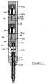
- the fuel injector comprises a nozzle body 10 provided with a blind bore 11 within which a valve member 12 is slidable.
- the bore 11 includes a region 11 a of reduced diameter and a region 11 b of larger diameter at its end remote from the region 11 a .
- the diameter of the valve member 12 adjacent the region 11 a is substantially the same as the diameter of the region 11 a such that the region 11 a serves to guide sliding movement of the valve member 12 within the bore 11.
- the region 11 b has substantially the same diameter as the adjacent part of the valve member 12 such that movement of the valve member 12 is also guided by the bore region 11 b .
- the bore 11 is also shaped to define a seating surface 11 c with which a surface of the valve needle 12 is engageable to control fuel delivery through a first set of outlet openings 14 provided in the nozzle body 10.
- the bore 11 defines an annular chamber 16, the annular chamber 16 being supplied with fuel under high pressure through a supply passage 18 formed in the nozzle body 10 and other parts of the fuel injector housing, from a source of high pressure fuel (not shown), for example the common rail of a common rail fuel system.
- the valve member 12 includes a region 12 a which defines, together with a part of the bore 11, a first delivery chamber 20 for fuel, the delivery chamber 20 communicating with the annular chamber 16 by means of a narrow clearance defined between the valve member 12 and the nozzle body 10 such that, in use, fuel delivered to the annular chamber 16 is able to flow into the chamber 20.
- the narrow clearance may be defined, in part, by grooves, flats or slots provided on the surface of the valve member 12.
- the valve member 12 is provided with a blind bore 22 within which a second valve member 24, or valve needle, is slidable, the bore 22 including a region 22 a of reduced diameter, having substantially the same diameter as the adjacent part of the valve needle 24, such that movement of the valve needle 24 within the bore 22 is guided by the bore region 22 a .
- the valve needle 24 includes, at its lowermost end, a region 24 a of enlarged diameter which is engageable with a seating 26 defined by a lower surface of the valve member 12 to control fuel delivery through a second set of outlet openings 28 provided in the valve needle 24.
- the bore 22 defines a step 22 b which abuts one end of a compression spring 38, the other end of the compression spring 38 being in abutment with a sleeve member 40 located within the bore 22 and through which the valve needle 24 extends.
- the spring 38 is arranged such that the valve needle region 24 a is biased against the seating 26.
- the valve needle 24 is also provided with a blind bore 30 which defines a flow passage 32 for fuel, the flow passage 32 communicating, via cross drillings 34 provided in the valve needle 24, with a second delivery chamber 36 defined by the bore 22 and the outer surface of the valve needle 24.
- the delivery chamber 36 communicates with the annular chamber 16 via cross drillings 35 provided in the valve member 12 such that, in use, when fuel under high pressure is supplied to the annular chamber 16, fuel is able to flow from the chamber 16 into the delivery chamber 36 through the drillings 35, and from the delivery chamber 36 into the flow passage 32 through the drillings 34.
- the valve needle 24 is moved outwardly away from the seating 26, fuel in the flow passage 32 is able to flow out through the second set of outlet openings 28.
- the nozzle body 10 abuts a distance piece 42 which is provided with a bore 44, a piston member 46 being slidable within the blind bore 44.
- the piston member 46 includes a stop member 46 a which serves to limit the extent of upward movement of the piston member 46 within the bore 44, in use.
- the piston member 46 defines a spring chamber 47 which houses a second compression spring 48.
- a nut 50 is also housed within the spring chamber 47, the nut 50 being in screw-threaded engagement with a projection 24 b at the uppermost end of the valve needle 24, the nut 50 being in abutment with the uppermost end surface of the sleeve member 40 and being retained in position by means of a locking pin member 52.
- One end of the compression spring 48 abuts a shim 54 connected with the upper end of the valve member 12 and the lower end surface of the piston member 46, the spring 48 acting on the shim 54 and, hence, the valve member 12 and serving to bias the valve member 12 in a downwards direction against the seating surface 11 c .
- the piston member 46 is further provided with a bore 56, which communicates with the spring chamber 47, a load transmitting member 58 being slidable within the bore 56.
- the lowermost end of the member 58 is in connection with the projection 24 a forming part of the valve needle 24 such that the member 58 is movable with the valve needle 24.
- the blind end of the bore 44 and the upper end face of the piston member 46 together define a first control chamber 60 for fuel, fuel under high pressure being supplied to the control chamber 60, in use, through a restricted drilling 62 provided in the distance piece 42 which communicates with a further drilling provided in the distance piece 42 forming part of the supply passage 18 for fuel.
- the distance piece 42 abuts, at its end remote from the nozzle body 10, a housing 64 which is provided with a blind bore 66 within which a second piston member 68 is slidable.
- the piston member 68 is provided with a blind bore which defines, in part, a spring chamber 71 for a compression spring 70, the load transmitting member 58 extending into the chamber 71.
- the lower end 78 of the piston member 68 is provided with a slot, the slotted lower end 78 of the piston member 68 and the upper end face of the distance piece 42 together defining a clearance gap 79 which serves to limit the extent of movement of the piston member 68 within the bore 66, in use.
- the upper end of the load transmitting member 58 and the blind end of the bore provided in the piston member 68 together define a clearance gap 85, the clearance gap 85 being smaller than the clearance gap 79 defined between the slotted end 78 of the piston member 68 and the distance piece 42 such that, in use, when the piston member 68 is moved in a downwards direction against the action of the spring 70 beyond an amount which exceeds the clearance gap 85, the blind end of the bore in the piston member 68 moves into engagement with the upper end surface of the load transmitting member 58, downward movement of the piston member 68 thereby being transmitted to the load transmitting member 58 and, thus, to the valve needle 24.
- the bore 66 provided in the housing 64 defines, together with the upper end face of the distance piece 42, a second control chamber 72 for fuel and the blind end of the bore 66 defines, together with the upper surface of the piston member 68, a third control chamber 80 for fuel, the third control chamber communicating with the spring chamber 71 by means of a restricted drilling 82 provided in the piston member 68.
- the control chamber 80 communicates with the supply passage 18 by means of a further drilling 84 provided in the housing 64 such that, in use, fuel under high pressure is supplied to the third control chamber 80 through the supply passage 18. Fuel supplied to the control chamber 80 is able to flow into the control chamber 72 at a relatively low rate by means of the restricted drilling 82.
- control chamber 60 and the control chamber 72 communicate with a low pressure fuel reservoir under the control of respective control valve arrangements, as will be described hereinafter, by means of drillings 61, 77 and drillings 74, 76 respectively provided in the distance piece 42 and the housing 64.
- the housing 64 abuts a further housing 88 within which a first control valve arrangement, referred to generally as 90, is arranged, the control valve arrangement 90 including a first valve member 92 which is moveable within a bore provided in the housing 88 under the action of an actuator arrangement 94 arranged within a housing 96.
- the actuator arrangement 94 shown in Figure 1 is an electromagnetic actuator arrangement which includes an armature 92 a in connection with the valve member 92.
- the injector includes a second control valve arrangement, referred to generally as 98, which is arranged within a further housing 103.
- the second control valve arrangement 98 comprises a second valve member 100 in connection with an armature 100 a of an associated electromagnetic actuator arrangement 102, the actuator arrangement 102 being arranged within a further housing 104. It will be appreciated, however, that the actuator arrangements 94, 102 need not be of the electromagnetic type and may, for example, be piezoelectric actuator arrangements.
- actuation and de-actuation of the actuator arrangements 94, 102 causes the armatures 100 a , 92 a respectively, and hence the valve members 100, 92 to move within their respective bores between open and closed positions.
- the valve member 100 is moved to an open position in which fuel within the second control chamber 72 is able to flow, via the drillings 74, 76, to the low pressure fuel reservoir or drain.
- the actuator arrangement 102 is de-actuated, the valve member 100 is moved to a closed position in which communication between the control chamber 72 and the low pressure fuel reservoir is broken.
- valve member 92 when the actuator arrangement 94 is actuated, the valve member 92 is moved to an open position in which fuel within the first control chamber 60 is able to flow, via the drillings 61, 77, to the low pressure fuel reservoir.
- the valve member 92 When the actuator arrangement 94 is de-actuated, the valve member 92 is moved to a closed position in which communication between the control chamber 60 and the low pressure fuel reservoir is broken.
- fuel under high pressure is supplied to the annular chamber 16 from the source of fuel at high pressure through the supply passage 18 defined by drillings provided in the housings 64, 88, 96, 104, the distance piece 42 and the nozzle body 10.
- Fuel in the annular chamber 16 is able to flow, via the drillings 35, into the second delivery chamber 36 and into the first delivery chamber 20 via the narrow clearance defined between the valve member 12 and the nozzle body 10.
- Fuel under high pressure is also supplied to the control chamber 60 via the drilling 62. As the valve member 92 is in its closed position, fuel supplied to the control chamber 60 is unable to flow to the low pressure reservoir.
- the surface of the piston member 46 is therefore exposed to fuel under high pressure within the control chamber 60, the force due to fuel pressure within the control chamber 60 thereby urging the piston member 46 in a downwards direction.
- the force applied to the piston member 46 is transmitted, via the spring 48 and the shim 54, to the valve member 12, the valve member 12 being urged against the seating surface 11 c due to the force applied to the piston member 46 and due to the spring force of the spring 48.
- With the valve member 12 seated against the seating 11 c fuel within the chamber 20 is unable to flow out through the first set of outlet openings 14 into the engine cylinder or other combustion space.
- fuel under high pressure is also supplied, via the drilling 84, to the control chamber 80, a force being applied to the surface of the piston member exposed to fuel within a control chamber 80 to urge the piston member 68 in a downwards direction.
- Fuel within the control chamber 80 is able to flow, at a restricted rate, through the drilling 82, into the spring chamber 71 and, thus, into the control chamber 72. With the valve member 100 in its closed position, high pressure fuel within the control chamber 72 is unable to flow to the low pressure fuel reservoir.
- the effective areas of the piston member 68 exposed to fuel pressure within the control chambers 80, 72 and the effective area of the sleeve 40 exposed to fuel pressure within the chamber 16, are chosen to ensure that, during this stage of operation, the valve needle 24 is urged is an upwards direction such that the enlarged valve needle region 24 a remains seated against the seating 26 and fuel delivery does not take place through the second set of outlet openings 28. Thus, during this stage of operation, fuel injection does not take place through either the first or second sets of outlet openings 14, 28.
- the actuator arrangement 94 When it is desired to commence fuel injection through the first set of outlet openings 14, the actuator arrangement 94 is actuated to move the valve member 92 to its open position, high pressure fuel within the control chamber 60 thereby being able to flow, via the drillings 61, 77, to the low pressure reservoir. As fuel pressure within the first control chamber 60 is reduced, the force applied to the surface of the piston member 46 is also reduced.
- the actuator arrangement 94 is de-actuated, thereby moving the valve member 92 to its closed position such that fuel pressure within the first control chamber 60 is increased.
- the force due to increased fuel pressure within the first control chamber 60, combined with the spring force 48, is sufficient to urge the piston member 46 and, hence, the valve member 12, in a downwards direction, thereby urging the valve member 12 against the seating surface 11 c to close communication between the first delivery chamber 20 and the first set of outlet openings 14.
- the force due to fuel under high pressure within the third control chamber 80 moves the piston member 68 downwardly into the position shown in Figure 5, the blind end of the bore provided in the piston member 68 abutting the load transmitting member 58 to move the member 58, and hence the valve needle 24, in a downwards direction against the force applied to the surface of the sleeve member 40 due to fuel pressure within the annular chamber 16.
- the enlarged region 24 a of the valve needle 24 is therefore moved away from the seating 26, fuel thereby being able to flow out through the second set of outlet openings 28.
- the actuator arrangement 102 is de-actuated, thereby moving the valve member 100 into its closed position such that high fuel pressure is re-established in the second control chamber 72, the piston member 68 and the valve needle 24 thereby being urged upwardly.
- the enlarged region 24 a of the valve needle 24 is urged against the seating 26 to close the second set of outlet openings 28, thereby terminating fuel injection.
- both the valve members 92, 100 are moved to their open positions, by actuating both actuator arrangements 90, 102 respectively, to reduce fuel pressure in both the first and second control chambers 60, 72.
- the valve member 12 is biased in an upwards direction, as the force applied to the surface of the piston member 46 exposed to fuel pressure in the first control chamber 60 is reduced, the valve member 12 thereby moving away from the seating surface 11 c to expose the first set of outlet openings 14.
- the piston member 68 is urged in a downwards direction.
- the valve needle 24 is also moved away from its seating 26 to expose the second set of outlet openings 28. Fuel injection therefore takes place through both the first and second sets of outlet openings 14, 28.
- first and second sets of outlet openings 14, 28 of different size, or having a different number of openings in each set, or having openings with a different spray cone angle selectively opening the first or second set of outlet openings 14, 28, or both sets of outlet openings, by controlling fuel pressure within the second and third control chambers 72, 80 permits the fuel injection characteristic to be varied, in use. Furthermore, fuel pressure within the flow passage 32 acts in a radially outwards direction, thereby serving to improve the seal between the valve member 12 and the nozzle body 10 and, in addition, the seal between the valve needle 24 and the valve member 12. Thus, leakage from the fuel injection is reduced.
- the arrangement is also advantageous as movement of the fuel member 12 and the valve needle 24 can be controlled with greater accuracy by controlling fuel pressure within the first and second control chambers 60 and 72.
Landscapes
- Engineering & Computer Science (AREA)
- Chemical & Material Sciences (AREA)
- Combustion & Propulsion (AREA)
- Mechanical Engineering (AREA)
- General Engineering & Computer Science (AREA)
- Physics & Mathematics (AREA)
- Fluid Mechanics (AREA)
- Fuel-Injection Apparatus (AREA)
Applications Claiming Priority (2)
| Application Number | Priority Date | Filing Date | Title |
|---|---|---|---|
| GB9922408 | 1999-09-23 | ||
| GBGB9922408.1A GB9922408D0 (en) | 1999-09-23 | 1999-09-23 | Fuel injector |
Publications (2)
| Publication Number | Publication Date |
|---|---|
| EP1087129A2 true EP1087129A2 (de) | 2001-03-28 |
| EP1087129A3 EP1087129A3 (de) | 2003-04-16 |
Family
ID=10861382
Family Applications (1)
| Application Number | Title | Priority Date | Filing Date |
|---|---|---|---|
| EP00307995A Withdrawn EP1087129A3 (de) | 1999-09-23 | 2000-09-14 | Kraftstoffeinspritzventil |
Country Status (3)
| Country | Link |
|---|---|
| US (1) | US6340121B1 (de) |
| EP (1) | EP1087129A3 (de) |
| GB (1) | GB9922408D0 (de) |
Cited By (6)
| Publication number | Priority date | Publication date | Assignee | Title |
|---|---|---|---|---|
| WO2003044358A1 (en) * | 2001-11-20 | 2003-05-30 | Westport Research, Inc. | Dual fuel injection valve and method of operating a dual fuel injection valve |
| WO2003054374A1 (de) * | 2001-12-20 | 2003-07-03 | Robert Bosch Gmbh | Kraftstoffeinspritzeinrichtung fuer eine brennkraftmaschine |
| EP1482167A1 (de) * | 2003-05-30 | 2004-12-01 | Siemens VDO Automotive S.p.A. | Ventilnadel, Dosiervorrichtung und Kalibrierungsverfahren einer Dosiervorrichtung |
| WO2005017342A1 (de) * | 2003-08-16 | 2005-02-24 | Robert Bosch Gmbh | Kraftstoff-einspritzvorrichtung, insbesondere für eine brennkraftmaschine mit direkteinspritzung |
| EP1584813A3 (de) * | 2004-04-08 | 2006-03-29 | Robert Bosch Gmbh | Kraftstoffeinspritzeinrichtung für Brennkraftmaschinen mit direkt ansteuerbaren Düsennadeln |
| EP2185804A4 (de) * | 2007-06-21 | 2015-08-12 | Corporation Quantlogic | Vormischverbrennungsverfahren, -vorrichtungen und diese verwendende motoren |
Families Citing this family (27)
| Publication number | Priority date | Publication date | Assignee | Title |
|---|---|---|---|---|
| GB9923823D0 (en) | 1999-10-09 | 1999-12-08 | Lucas Industries Ltd | Fuel injector |
| DE10010863A1 (de) * | 2000-03-06 | 2001-09-27 | Bosch Gmbh Robert | Einspritzdüse |
| ATE353118T1 (de) | 2000-07-18 | 2007-02-15 | Delphi Tech Inc | Kraftstoffeinspritzventil |
| US6557779B2 (en) * | 2001-03-02 | 2003-05-06 | Cummins Engine Company, Inc. | Variable spray hole fuel injector with dual actuators |
| GB0107575D0 (en) * | 2001-03-27 | 2001-05-16 | Delphi Tech Inc | Control valve arrangement |
| US6637675B2 (en) * | 2001-07-13 | 2003-10-28 | Cummins Inc. | Rate shaping fuel injector with limited throttling |
| US6557776B2 (en) * | 2001-07-19 | 2003-05-06 | Cummins Inc. | Fuel injector with injection rate control |
| US6725838B2 (en) | 2001-10-09 | 2004-04-27 | Caterpillar Inc | Fuel injector having dual mode capabilities and engine using same |
| DE10158789A1 (de) * | 2001-11-30 | 2003-07-10 | Bosch Gmbh Robert | Brennstoffeinspritzventil |
| US7252249B2 (en) * | 2002-02-22 | 2007-08-07 | Delphi Technologies, Inc. | Solenoid-type fuel injector assembly having stabilized ferritic stainless steel components |
| DE10222196A1 (de) * | 2002-05-18 | 2003-11-27 | Bosch Gmbh Robert | Kraftstoffeinspritzventil für Brennkraftmaschinen |
| US6824081B2 (en) * | 2002-06-28 | 2004-11-30 | Cummins Inc. | Needle controlled fuel injector with two control valves |
| US6978760B2 (en) * | 2002-09-25 | 2005-12-27 | Caterpillar Inc | Mixed mode fuel injector and injection system |
| US6945475B2 (en) | 2002-12-05 | 2005-09-20 | Caterpillar Inc | Dual mode fuel injection system and fuel injector for same |
| DE10304605A1 (de) * | 2003-02-05 | 2004-08-19 | Robert Bosch Gmbh | Kraftstoffeinspritzventil mit zwei koaxialen Ventilnadeln |
| US6843434B2 (en) * | 2003-02-28 | 2005-01-18 | Caterpillar Inc | Dual mode fuel injector with one piece needle valve member |
| WO2007122841A1 (ja) * | 2006-03-29 | 2007-11-01 | Keihin Corporation | 燃料噴射弁 |
| DE102006019308A1 (de) * | 2006-04-26 | 2007-10-31 | Robert Bosch Gmbh | Injektor |
| US7685990B2 (en) * | 2007-11-29 | 2010-03-30 | Delphi Technologies, Inc. | Dual mode combustion apparatus and method |
| WO2009091685A1 (en) * | 2008-01-14 | 2009-07-23 | North Carolina State University | Fuel injection device for an internal combustion engine, and associated method |
| KR101144482B1 (ko) * | 2010-10-06 | 2012-05-11 | (주)제너진 | 엔진의 직분사 인젝터 |
| US20130199501A1 (en) * | 2010-10-11 | 2013-08-08 | A Fuel Injector With A Variable Orifice | Fuel injector with a variable orifice |
| US20130213358A1 (en) * | 2010-10-15 | 2013-08-22 | Deyang Hou | Fuel injector capable of dual fuel injection |
| EP2602476A1 (de) * | 2011-12-07 | 2013-06-12 | Continental Automotive GmbH | Ventilanordnung für ein Einspritzventil und Einspritzventil |
| EP2672101A1 (de) * | 2012-06-05 | 2013-12-11 | Caterpillar Motoren GmbH & Co. KG | Einspritzdüse |
| GB201309118D0 (en) | 2013-05-21 | 2013-07-03 | Delphi Tech Holding Sarl | Fuel Injector |
| CN114458498B (zh) * | 2022-02-24 | 2022-10-28 | 哈尔滨工程大学 | 一种基于节流阻容效应实现高稳定喷射的高压共轨喷油器 |
Family Cites Families (12)
| Publication number | Priority date | Publication date | Assignee | Title |
|---|---|---|---|---|
| US3339848A (en) * | 1965-10-20 | 1967-09-05 | Int Harvester Co | Fuel injection nozzle |
| DE1808650A1 (de) * | 1968-11-13 | 1970-06-18 | Bosch Gmbh Robert | Kraftstoffeinspritzvorrichtung |
| DE2726296A1 (de) * | 1977-06-10 | 1978-12-21 | Bosch Gmbh Robert | Kraftstoffeinspritzduese |
| DE3266767D1 (en) * | 1981-05-20 | 1985-11-14 | Bosch Gmbh Robert | Fuel injection nozzle for internal-combustion engines |
| DE3236046C2 (de) * | 1982-09-29 | 1986-03-20 | Daimler-Benz Ag, 7000 Stuttgart | Kraftstoffeinspritzdüse für Brennkraftmaschinen |
| JPS6036772A (ja) * | 1983-08-10 | 1985-02-25 | Diesel Kiki Co Ltd | 燃料噴射弁 |
| DE4115477C2 (de) * | 1990-05-17 | 2003-02-06 | Avl Verbrennungskraft Messtech | Einspritzdüse für eine Brennkraftmaschine |
| DE4340305C2 (de) * | 1993-11-26 | 1998-02-19 | Daimler Benz Ag | Kraftstoffeinspritzdüse für eine Brennkraftmaschine |
| US5458292A (en) * | 1994-05-16 | 1995-10-17 | General Electric Company | Two-stage fuel injection nozzle |
| JPH08226363A (ja) * | 1995-02-20 | 1996-09-03 | Zexel Corp | 燃料噴射ノズル |
| US5899389A (en) * | 1997-06-02 | 1999-05-04 | Cummins Engine Company, Inc. | Two stage fuel injector nozzle assembly |
| GB9905231D0 (en) * | 1999-03-09 | 1999-04-28 | Lucas Ind Plc | Fuel injector |
-
1999
- 1999-09-23 GB GBGB9922408.1A patent/GB9922408D0/en not_active Ceased
-
2000
- 2000-09-14 EP EP00307995A patent/EP1087129A3/de not_active Withdrawn
- 2000-09-15 US US09/662,616 patent/US6340121B1/en not_active Expired - Fee Related
Non-Patent Citations (1)
| Title |
|---|
| None |
Cited By (10)
| Publication number | Priority date | Publication date | Assignee | Title |
|---|---|---|---|---|
| WO2003044358A1 (en) * | 2001-11-20 | 2003-05-30 | Westport Research, Inc. | Dual fuel injection valve and method of operating a dual fuel injection valve |
| CN100359155C (zh) * | 2001-11-20 | 2008-01-02 | 韦斯特波特动力股份有限公司 | 双燃料喷射阀以及操作双燃料喷射阀的方法 |
| WO2003054374A1 (de) * | 2001-12-20 | 2003-07-03 | Robert Bosch Gmbh | Kraftstoffeinspritzeinrichtung fuer eine brennkraftmaschine |
| US6896208B2 (en) | 2001-12-20 | 2005-05-24 | Robert Bosch Gmbh | Fuel injection system for an internal combustion engine |
| CN100379975C (zh) * | 2001-12-20 | 2008-04-09 | 罗伯特·博施有限公司 | 用于内燃机的燃料喷射装置 |
| EP1482167A1 (de) * | 2003-05-30 | 2004-12-01 | Siemens VDO Automotive S.p.A. | Ventilnadel, Dosiervorrichtung und Kalibrierungsverfahren einer Dosiervorrichtung |
| WO2004106726A1 (en) * | 2003-05-30 | 2004-12-09 | Siemens Vdo Automotive S.P.A. | Valve needle, metering device, and method of calibrating a metering device |
| WO2005017342A1 (de) * | 2003-08-16 | 2005-02-24 | Robert Bosch Gmbh | Kraftstoff-einspritzvorrichtung, insbesondere für eine brennkraftmaschine mit direkteinspritzung |
| EP1584813A3 (de) * | 2004-04-08 | 2006-03-29 | Robert Bosch Gmbh | Kraftstoffeinspritzeinrichtung für Brennkraftmaschinen mit direkt ansteuerbaren Düsennadeln |
| EP2185804A4 (de) * | 2007-06-21 | 2015-08-12 | Corporation Quantlogic | Vormischverbrennungsverfahren, -vorrichtungen und diese verwendende motoren |
Also Published As
| Publication number | Publication date |
|---|---|
| EP1087129A3 (de) | 2003-04-16 |
| GB9922408D0 (en) | 1999-11-24 |
| US6340121B1 (en) | 2002-01-22 |
Similar Documents
| Publication | Publication Date | Title |
|---|---|---|
| US6340121B1 (en) | Fuel injector | |
| US6378503B1 (en) | Fuel injector | |
| EP1079094B1 (de) | Kraftstoffeinspritzventil | |
| US6220528B1 (en) | Fuel injector including an outer valve needle, and inner valve needle slidable within a bore formed in the outer valve needle | |
| US6776354B2 (en) | Fuel injector | |
| US6616070B1 (en) | Fuel injector | |
| US5505384A (en) | Rate shaping control valve for fuel injection nozzle | |
| EP1693562B1 (de) | Brennstoffeinspritzventil | |
| EP2273097B1 (de) | Kraftstoffeinspritzdüse | |
| EP0943797A1 (de) | Kraftstoffeinspritzventil | |
| EP1245822B1 (de) | Einspritzventil mit einem Durchflussbegrenzer in dem Steuerventil | |
| US6425368B1 (en) | Fuel injector | |
| US6340017B1 (en) | Fuel injector | |
| EP1837518B1 (de) | Dämpfungsanordnung für ein Einspritzventil | |
| US7568634B2 (en) | Injection nozzle | |
| EP1643117B1 (de) | Einspritzdüse | |
| EP1373705A1 (de) | Kraftstoffeinspritzdüse für brennkraftmaschine | |
| EP1744050A1 (de) | Einspritzdüse | |
| US6591812B2 (en) | Rail connection with rate shaping behavior for a hydraulically actuated fuel injector | |
| EP1079096B1 (de) | Kraftstoffeinspritzanordnung | |
| EP1063422B1 (de) | Kraftstoffeinspritzventil |
Legal Events
| Date | Code | Title | Description |
|---|---|---|---|
| PUAI | Public reference made under article 153(3) epc to a published international application that has entered the european phase |
Free format text: ORIGINAL CODE: 0009012 |
|
| AK | Designated contracting states |
Kind code of ref document: A2 Designated state(s): AT BE CH CY DE DK ES FI FR GB GR IE IT LI LU MC NL PT SE |
|
| AX | Request for extension of the european patent |
Free format text: AL;LT;LV;MK;RO;SI |
|
| PUAL | Search report despatched |
Free format text: ORIGINAL CODE: 0009013 |
|
| AK | Designated contracting states |
Designated state(s): AT BE CH CY DE DK ES FI FR GB GR IE IT LI LU MC NL PT SE |
|
| AX | Request for extension of the european patent |
Extension state: AL LT LV MK RO SI |
|
| RIC1 | Information provided on ipc code assigned before grant |
Ipc: 7F 02M 47/02 B Ipc: 7F 02M 61/16 B Ipc: 7F 02M 61/08 B Ipc: 7F 02M 45/08 A |
|
| 17P | Request for examination filed |
Effective date: 20030925 |
|
| AKX | Designation fees paid |
Designated state(s): AT BE CH CY DE DK ES FI FR GB GR IE IT LI LU MC NL PT SE |
|
| STAA | Information on the status of an ep patent application or granted ep patent |
Free format text: STATUS: THE APPLICATION IS DEEMED TO BE WITHDRAWN |
|
| 18D | Application deemed to be withdrawn |
Effective date: 20060523 |