EP1087100A2 - Kompressorrotor- Konfiguration - Google Patents
Kompressorrotor- Konfiguration Download PDFInfo
- Publication number
- EP1087100A2 EP1087100A2 EP00306179A EP00306179A EP1087100A2 EP 1087100 A2 EP1087100 A2 EP 1087100A2 EP 00306179 A EP00306179 A EP 00306179A EP 00306179 A EP00306179 A EP 00306179A EP 1087100 A2 EP1087100 A2 EP 1087100A2
- Authority
- EP
- European Patent Office
- Prior art keywords
- rim
- rotor
- blades
- gas turbine
- accordance
- Prior art date
- Legal status (The legal status is an assumption and is not a legal conclusion. Google has not performed a legal analysis and makes no representation as to the accuracy of the status listed.)
- Granted
Links
Images


Classifications
-
- F—MECHANICAL ENGINEERING; LIGHTING; HEATING; WEAPONS; BLASTING
- F01—MACHINES OR ENGINES IN GENERAL; ENGINE PLANTS IN GENERAL; STEAM ENGINES
- F01D—NON-POSITIVE DISPLACEMENT MACHINES OR ENGINES, e.g. STEAM TURBINES
- F01D5/00—Blades; Blade-carrying members; Heating, heat-insulating, cooling or antivibration means on the blades or the members
- F01D5/12—Blades
- F01D5/14—Form or construction
- F01D5/141—Shape, i.e. outer, aerodynamic form
- F01D5/142—Shape, i.e. outer, aerodynamic form of the blades of successive rotor or stator blade-rows
- F01D5/143—Contour of the outer or inner working fluid flow path wall, i.e. shroud or hub contour
-
- F—MECHANICAL ENGINEERING; LIGHTING; HEATING; WEAPONS; BLASTING
- F01—MACHINES OR ENGINES IN GENERAL; ENGINE PLANTS IN GENERAL; STEAM ENGINES
- F01D—NON-POSITIVE DISPLACEMENT MACHINES OR ENGINES, e.g. STEAM TURBINES
- F01D5/00—Blades; Blade-carrying members; Heating, heat-insulating, cooling or antivibration means on the blades or the members
- F01D5/02—Blade-carrying members, e.g. rotors
- F01D5/06—Rotors for more than one axial stage, e.g. of drum or multiple disc type; Details thereof, e.g. shafts, shaft connections
-
- F—MECHANICAL ENGINEERING; LIGHTING; HEATING; WEAPONS; BLASTING
- F04—POSITIVE - DISPLACEMENT MACHINES FOR LIQUIDS; PUMPS FOR LIQUIDS OR ELASTIC FLUIDS
- F04D—NON-POSITIVE-DISPLACEMENT PUMPS
- F04D29/00—Details, component parts, or accessories
- F04D29/26—Rotors specially for elastic fluids
- F04D29/32—Rotors specially for elastic fluids for axial flow pumps
- F04D29/321—Rotors specially for elastic fluids for axial flow pumps for axial flow compressors
-
- F—MECHANICAL ENGINEERING; LIGHTING; HEATING; WEAPONS; BLASTING
- F05—INDEXING SCHEMES RELATING TO ENGINES OR PUMPS IN VARIOUS SUBCLASSES OF CLASSES F01-F04
- F05D—INDEXING SCHEME FOR ASPECTS RELATING TO NON-POSITIVE-DISPLACEMENT MACHINES OR ENGINES, GAS-TURBINES OR JET-PROPULSION PLANTS
- F05D2250/00—Geometry
- F05D2250/70—Shape
Definitions
- This invention relates generally to gas turbine engines and, more specifically, to a flowpath through a compressor rotor.
- a gas turbine engine typically includes a multi-stage axial compressor with a number of compressor blade or airfoil rows extending radially outwardly from a common annular rim.
- the outer surface of the rotor rim typically defines the radially inner flowpath surface of the compressor as air is compressed from stage to stage.
- Centrifugal forces generated by the rotating blades are carried by portions of the rim directly below the blades. The centrifugal forces generate circumferential rim stress concentration between the rim and the blades.
- a thermal gradient between the annular rim and compressor bore during transient operations generates thermal stress which adversely impacts a low cycle fatigue (LCF) life of the rim.
- LCF low cycle fatigue
- the rim is exposed directly to the flowpath air, which increases the thermal gradient and the rim stress.
- blade roots generate local forces which further increase rim stress.
- the present invention in one aspect, is a gas turbine engine rotor assembly including a rotor having a radially outer rim with an outer surface shaped to reduce rim stress between the outer rim and a blade and to direct air flow away from an interface between a blade and the rim, thus reducing aerodynamic performance losses.
- the disk includes a radially inner hub, and a web extending between the hub and the rim, and a plurality of circumferentially spaced apart rotor blades extending radially outwardly from the rim.
- the outer surface of the rim has a concave shape between adjacent blades with apexes located at interfaces between the blades and the rim.
- the outer surface of the rotor rim defines the radially inner flowpath surface of the compressor as air is compressed from stage to stage.
- rim stress between the blade and the rim is reduced.
- the concave shape generally directs airflow away from immediately adjacent to the blade / rim interface and more towards a center of the flowpath between the adjacent blades. As a result, aerodynamic performance losses are reduced. Reducing such rim stress facilitates increasing the LCF life of the rim.
- FIG. 1 is a schematic illustration of a portion of a compressor rotor assembly 10.
- Rotor assembly 10 includes rotors 12 joined together by couplings 14 coaxially about an axial centerline axis (not shown).
- Each rotor 12 is formed by one or more blisks 16, and each blisk 16 includes a radially outer rim 18, a radially inner hub 20, and an integral web 22 extending radially therebetween.
- An interior area within rim 18 sometimes is referred to as a compressor bore.
- Each blisk 16 also includes a plurality of blades 24 extending radially outwardly from rim 16. Blades 24, in the embodiment illustrated in Figure 1, are integrally joined with respective rims 18.
- each rotor blade may be removably joined to the rims in a known manner using blade dovetails which mount in complementary slots in the respective rim.
- rotor assembly 10 is a compressor of a gas turbine engine, with rotor blades 24 configured for suitably compressing the motive fluid air in succeeding stages.
- Outer surfaces 26 of rotor rims 18 define the radially inner flowpath surface of the compressor as air is compressed from stage to stage.
- Blades 24 rotate about the axial centerline axis up to a specific maximum design rotational speed, and generate centrifugal loads in the rotating components. Centrifugal forces generated by rotating blades 24 are carried by portions of rims 18 directly below each blade 24.
- FIG 2 is a forward view of a portion of a known compressor stage rotor 100.
- Rotor 100 includes a plurality of blades 102 extending from a rim 104.
- a radially outer surface 106 of rim 104 defines the radially inner flowpath, and air flows between adjacent blades 102.
- a thermal gradient between annular rim 104 and compressor bore 108 particularly during transient operations generates thermal stress which adversely impacts the low cycle fatigue (LCF) life of rim 104.
- rim 104 is exposed directly to the flowpath air, which increases both the thermal gradient between rim 104 and bore 108. The increase in the thermal gradient increases the circumferential rim stress.
- roots 110 of blades 102 generate local forces and stress concentrations which further increase rim stress.
- the outer surface of the rim is configured to have a holly leaf shape.
- the respective blades are located at each apex of the holly leaf shaped rim, which provides the advantage that peak stresses in the rim are not located at the blade / rim intersection and stress concentrations are reduced which facilitates extending the LCF life of the rim.
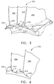
- Figure 3 is a forward view of a portion of a compressor stage rotor 200 in accordance with one embodiment of the present invention.
- Rotor 200 includes a rim 202 having an outer rim surface 204.
- a plurality of blades 206 extend from rim surface 204.
- Rim surface 204 is holly leaf shaped in that surface 204 includes a plurality of apexes 208 separated by a concave shaped curved surface 210 between adjacent apexes 208.
- the holly leaf shape is generated as a compound radius having a first radius A and a second radius B.
- First radius A is between approximately 0.04 inches and 0.5 inches and typically second radius B is approximately 2 to 10 times a distance between adjacent blades 206.
- first radius A is approximately 0.06 inches and a second radius B is approximately 2.0 inches.
- Figure 4 is an aft view of a portion of the compressor stage rotor 200.
- rim surface 204 is holly leaf shaped and includes a plurality of apexes 214 separated by a concave shaped curved surface 216 between adjacent apexes 214.
- the holly leaf shape is generated as a compound radius having a first radius C and a second radius D.
- First radius C is between approximately 0.04 inches and 0.5 inches and typically second radius D is approximately 2 to 10 times a distance between adjacent blades 206.
- first radius C is approximately 0.06 inches and second radius D is approximately 2.0 inches.
- Rim surface 204 can be cast or machined to include the above-described shape.
- rim surface 204 can be formed after fabrication of rim 202 by, for example, securing blades 206 to rim 202 by fillet welds.
- blades 206 are secured to rim 202 by friction welds or other methods. Specifically, the welds can be made so that the desired shape for the flowpath between adjacent blades 206 is provided.
- outer surface 204 of rotor rim 202 defines the radially inner flowpath surface of the compressor as air is compressed from stage to stage.
- outer surface 204 has a concave shape between adjacent blades 206, airflow is generally directed away from immediately adjacent the blade / rim interface and more towards a center of the flowpath between adjacent blades 206 which reduces aerodynamic performance losses.
- less circumferential rim stress concentration is generated between rim 202 and blades 206 at the location of the blade / rim interface. Reducing such at the interface facilitates extending the LCF life of rim 202.
Landscapes
- Engineering & Computer Science (AREA)
- Mechanical Engineering (AREA)
- General Engineering & Computer Science (AREA)
- Physics & Mathematics (AREA)
- Fluid Mechanics (AREA)
- Structures Of Non-Positive Displacement Pumps (AREA)
- Turbine Rotor Nozzle Sealing (AREA)
- Applications Or Details Of Rotary Compressors (AREA)
Applications Claiming Priority (2)
| Application Number | Priority Date | Filing Date | Title |
|---|---|---|---|
| US405308 | 1999-09-23 | ||
| US09/405,308 US6511294B1 (en) | 1999-09-23 | 1999-09-23 | Reduced-stress compressor blisk flowpath |
Publications (3)
| Publication Number | Publication Date |
|---|---|
| EP1087100A2 true EP1087100A2 (de) | 2001-03-28 |
| EP1087100A3 EP1087100A3 (de) | 2004-01-02 |
| EP1087100B1 EP1087100B1 (de) | 2010-04-21 |
Family
ID=23603138
Family Applications (1)
| Application Number | Title | Priority Date | Filing Date |
|---|---|---|---|
| EP00306179A Expired - Lifetime EP1087100B1 (de) | 1999-09-23 | 2000-07-20 | Kompressorrotor- Konfiguration |
Country Status (7)
| Country | Link |
|---|---|
| US (1) | US6511294B1 (de) |
| EP (1) | EP1087100B1 (de) |
| JP (1) | JP4856302B2 (de) |
| AT (1) | ATE465325T1 (de) |
| BR (1) | BR0003109A (de) |
| CA (1) | CA2313929C (de) |
| DE (1) | DE60044228D1 (de) |
Cited By (15)
| Publication number | Priority date | Publication date | Assignee | Title |
|---|---|---|---|---|
| EP1199439A2 (de) * | 2000-10-20 | 2002-04-24 | General Electric Company | Konfiguration zur Verminderung der Umfangsspannung am Rande einer Rotoranordnung |
| EP1182328A3 (de) * | 2000-08-21 | 2003-06-04 | General Electric Company | Methode zur Verringerung der Umfangsspanung in Rotoren |
| FR2836954A1 (fr) * | 2002-03-07 | 2003-09-12 | United Technologies Corp | Profil de paroi d'extremite pour une utilisation dans les turbomachines |
| EP1496266A1 (de) * | 2003-07-11 | 2005-01-12 | Snecma Moteurs | Verbindung zwischen Schaufelscheiben eines Verdichterrotors |
| GB2411441A (en) * | 2004-02-24 | 2005-08-31 | Rolls Royce Plc | Fan or compressor blisk |
| FR2926856A1 (fr) * | 2008-01-30 | 2009-07-31 | Snecma Sa | Compresseur de turboreacteur |
| EP2003292A3 (de) * | 2007-06-14 | 2012-04-04 | Rolls-Royce Deutschland Ltd & Co KG | Schaufeldeckband mit Überstand |
| EP2372088A3 (de) * | 2009-09-16 | 2014-12-03 | United Technologies Corporation | Turbolüfterfließwegkanal |
| EP2713013A4 (de) * | 2011-05-13 | 2015-03-04 | Ihi Corp | Gasturbinenmotor |
| EP3051067A1 (de) * | 2015-01-15 | 2016-08-03 | United Technologies Corporation | Gasturbinenmotorschaufel mit verkürztem einlass |
| US9512727B2 (en) | 2011-03-28 | 2016-12-06 | Rolls-Royce Deutschland Ltd & Co Kg | Rotor of an axial compressor stage of a turbomachine |
| US9816528B2 (en) | 2011-04-20 | 2017-11-14 | Rolls-Royce Deutschland Ltd & Co Kg | Fluid-flow machine |
| US9822795B2 (en) | 2011-03-28 | 2017-11-21 | Rolls-Royce Deutschland Ltd & Co Kg | Stator of an axial compressor stage of a turbomachine |
| EP3431713A1 (de) * | 2017-07-18 | 2019-01-23 | United Technologies Corporation | Integral beschaufelte rotoren und zugehöriges gasturbinentriebwerk |
| DE102022113750A1 (de) | 2022-05-31 | 2023-11-30 | MTU Aero Engines AG | Ringraumkonturierung |
Families Citing this family (47)
| Publication number | Priority date | Publication date | Assignee | Title |
|---|---|---|---|---|
| GB0411850D0 (en) * | 2004-05-27 | 2004-06-30 | Rolls Royce Plc | Spacing arrangement |
| DE102004026386A1 (de) * | 2004-05-29 | 2005-12-22 | Mtu Aero Engines Gmbh | Schaufelblatt einer Strömungsmaschine sowie Strömungsmaschine |
| US7269955B2 (en) * | 2004-08-25 | 2007-09-18 | General Electric Company | Methods and apparatus for maintaining rotor assembly tip clearances |
| US7690890B2 (en) * | 2004-09-24 | 2010-04-06 | Ishikawajima-Harima Heavy Industries Co. Ltd. | Wall configuration of axial-flow machine, and gas turbine engine |
| US7217096B2 (en) * | 2004-12-13 | 2007-05-15 | General Electric Company | Fillet energized turbine stage |
| US7134842B2 (en) * | 2004-12-24 | 2006-11-14 | General Electric Company | Scalloped surface turbine stage |
| US7249933B2 (en) * | 2005-01-10 | 2007-07-31 | General Electric Company | Funnel fillet turbine stage |
| US7220100B2 (en) * | 2005-04-14 | 2007-05-22 | General Electric Company | Crescentic ramp turbine stage |
| US7371046B2 (en) * | 2005-06-06 | 2008-05-13 | General Electric Company | Turbine airfoil with variable and compound fillet |
| US20070031260A1 (en) * | 2005-08-03 | 2007-02-08 | Dube Bryan P | Turbine airfoil platform platypus for low buttress stress |
| US7465155B2 (en) | 2006-02-27 | 2008-12-16 | Honeywell International Inc. | Non-axisymmetric end wall contouring for a turbomachine blade row |
| US20080135721A1 (en) * | 2006-12-06 | 2008-06-12 | General Electric Company | Casting compositions for manufacturing metal casting and methods of manufacturing thereof |
| US8413709B2 (en) * | 2006-12-06 | 2013-04-09 | General Electric Company | Composite core die, methods of manufacture thereof and articles manufactured therefrom |
| US7938168B2 (en) * | 2006-12-06 | 2011-05-10 | General Electric Company | Ceramic cores, methods of manufacture thereof and articles manufactured from the same |
| US7624787B2 (en) * | 2006-12-06 | 2009-12-01 | General Electric Company | Disposable insert, and use thereof in a method for manufacturing an airfoil |
| US7487819B2 (en) * | 2006-12-11 | 2009-02-10 | General Electric Company | Disposable thin wall core die, methods of manufacture thereof and articles manufactured therefrom |
| US8884182B2 (en) | 2006-12-11 | 2014-11-11 | General Electric Company | Method of modifying the end wall contour in a turbine using laser consolidation and the turbines derived therefrom |
| JP5283855B2 (ja) * | 2007-03-29 | 2013-09-04 | 株式会社Ihi | ターボ機械の壁、及びターボ機械 |
| US8313291B2 (en) * | 2007-12-19 | 2012-11-20 | Nuovo Pignone, S.P.A. | Turbine inlet guide vane with scalloped platform and related method |
| WO2009105208A2 (en) * | 2008-02-22 | 2009-08-27 | Horton, Inc. | Fan manufacturing and assembly |
| US8647067B2 (en) * | 2008-12-09 | 2014-02-11 | General Electric Company | Banked platform turbine blade |
| US8459956B2 (en) * | 2008-12-24 | 2013-06-11 | General Electric Company | Curved platform turbine blade |
| US8439643B2 (en) * | 2009-08-20 | 2013-05-14 | General Electric Company | Biformal platform turbine blade |
| US8480368B2 (en) * | 2010-02-05 | 2013-07-09 | General Electric Company | Welding process and component produced therefrom |
| US8636195B2 (en) * | 2010-02-19 | 2014-01-28 | General Electric Company | Welding process and component formed thereby |
| US8356975B2 (en) * | 2010-03-23 | 2013-01-22 | United Technologies Corporation | Gas turbine engine with non-axisymmetric surface contoured vane platform |
| US9976433B2 (en) * | 2010-04-02 | 2018-05-22 | United Technologies Corporation | Gas turbine engine with non-axisymmetric surface contoured rotor blade platform |
| US9045990B2 (en) * | 2011-05-26 | 2015-06-02 | United Technologies Corporation | Integrated ceramic matrix composite rotor disk geometry for a gas turbine engine |
| US8721291B2 (en) | 2011-07-12 | 2014-05-13 | Siemens Energy, Inc. | Flow directing member for gas turbine engine |
| US8864452B2 (en) | 2011-07-12 | 2014-10-21 | Siemens Energy, Inc. | Flow directing member for gas turbine engine |
| US10077663B2 (en) | 2011-09-29 | 2018-09-18 | United Technologies Corporation | Gas turbine engine rotor stack assembly |
| US9169730B2 (en) | 2011-11-16 | 2015-10-27 | Pratt & Whitney Canada Corp. | Fan hub design |
| BR112014026360A2 (pt) | 2012-04-23 | 2017-06-27 | Gen Electric | aerofólio de turbina e pá de turbina |
| US9267386B2 (en) | 2012-06-29 | 2016-02-23 | United Technologies Corporation | Fairing assembly |
| EP2885506B8 (de) | 2012-08-17 | 2021-03-31 | Raytheon Technologies Corporation | Profilierte durchflusswegfläche |
| US20140154068A1 (en) * | 2012-09-28 | 2014-06-05 | United Technologies Corporation | Endwall Controuring |
| EP2959108B1 (de) | 2013-02-21 | 2021-04-21 | Raytheon Technologies Corporation | Gasturbinenmotor mit verstimmter stufe |
| WO2014197062A2 (en) | 2013-03-15 | 2014-12-11 | United Technologies Corporation | Fan exit guide vane platform contouring |
| EP2806103B1 (de) * | 2013-05-24 | 2019-07-17 | MTU Aero Engines AG | Schaufelgitter und Strömungsmaschine |
| WO2015023331A2 (en) | 2013-06-10 | 2015-02-19 | United Technologies Corporation | Turbine vane with non-uniform wall thickness |
| US9938984B2 (en) * | 2014-12-29 | 2018-04-10 | General Electric Company | Axial compressor rotor incorporating non-axisymmetric hub flowpath and splittered blades |
| US9874221B2 (en) * | 2014-12-29 | 2018-01-23 | General Electric Company | Axial compressor rotor incorporating splitter blades |
| US20160208613A1 (en) * | 2015-01-15 | 2016-07-21 | United Technologies Corporation | Gas turbine engine integrally bladed rotor |
| CN110529428A (zh) * | 2019-08-13 | 2019-12-03 | 中国航发贵阳发动机设计研究所 | 一种中涵道比航空发动机悬臂式增压级三级转子 |
| CN113931872B (zh) * | 2021-12-15 | 2022-03-18 | 成都中科翼能科技有限公司 | 一种燃气轮机压气机的双层鼓筒加强型转子结构 |
| CN114033744B (zh) * | 2022-01-11 | 2022-03-25 | 成都中科翼能科技有限公司 | 一种新型燃气轮机低压压气机转子结构及装配方法 |
| US11898467B2 (en) | 2022-02-11 | 2024-02-13 | Pratt & Whitney Canada Corp. | Aircraft engine struts with stiffening protrusions |
Family Cites Families (51)
| Publication number | Priority date | Publication date | Assignee | Title |
|---|---|---|---|---|
| US2735612A (en) | 1956-02-21 | hausmann | ||
| US1793468A (en) | 1929-05-28 | 1931-02-24 | Westinghouse Electric & Mfg Co | Turbine blade |
| US2429324A (en) | 1943-12-30 | 1947-10-21 | Meisser Christian | Rotor for centrifugal compressors |
| US2415380A (en) | 1944-11-15 | 1947-02-04 | Weber Max | Propeller blade |
| US2790620A (en) | 1952-07-09 | 1957-04-30 | Gen Electric | Multiple finger dovetail attachment for turbine bucket |
| US2918254A (en) | 1954-05-10 | 1959-12-22 | Hausammann Werner | Turborunner |
| US3095180A (en) | 1959-03-05 | 1963-06-25 | Stalker Corp | Blades for compressors, turbines and the like |
| FR1442526A (fr) | 1965-05-07 | 1966-06-17 | Rateau Soc | Perfectionnements aux canaux courbes parcourus par un gaz ou une vapeur |
| GB1119392A (en) | 1966-06-03 | 1968-07-10 | Rover Co Ltd | Axial flow rotor for a turbine or the like |
| US3481531A (en) | 1968-03-07 | 1969-12-02 | United Aircraft Canada | Impeller boundary layer control device |
| US3584969A (en) | 1968-05-25 | 1971-06-15 | Aisin Seiki | Flexible blade fan |
| GB1302036A (de) | 1969-06-26 | 1973-01-04 | ||
| US3661475A (en) | 1970-04-30 | 1972-05-09 | Gen Electric | Turbomachinery rotors |
| US3890062A (en) | 1972-06-28 | 1975-06-17 | Us Energy | Blade transition for axial-flow compressors and the like |
| US3927952A (en) | 1972-11-20 | 1975-12-23 | Garrett Corp | Cooled turbine components and method of making the same |
| US3891351A (en) * | 1974-03-25 | 1975-06-24 | Theodore J Norbut | Turbine disc |
| US3888602A (en) * | 1974-06-05 | 1975-06-10 | United Aircraft Corp | Stress restraining ring for compressor rotors |
| US3897171A (en) * | 1974-06-25 | 1975-07-29 | Westinghouse Electric Corp | Ceramic turbine rotor disc and blade configuration |
| US3951611A (en) | 1974-11-14 | 1976-04-20 | Morrill Wayne J | Blank for fan blade |
| NO146029C (no) | 1976-08-11 | 1982-07-14 | Kongsberg Vapenfab As | Impellerelement i et radialgassturbinhjul |
| US4062638A (en) * | 1976-09-16 | 1977-12-13 | General Motors Corporation | Turbine wheel with shear configured stress discontinuity |
| US4135857A (en) | 1977-06-09 | 1979-01-23 | United Technologies Corporation | Reduced drag airfoil platforms |
| SU756083A1 (ru) * | 1978-07-18 | 1980-08-15 | Vladislav D Lubenets | Рабочее колесо вихревой машины 1 |
| US4335997A (en) | 1980-01-16 | 1982-06-22 | General Motors Corporation | Stress resistant hybrid radial turbine wheel |
| DE3023466C2 (de) | 1980-06-24 | 1982-11-25 | MTU Motoren- und Turbinen-Union München GmbH, 8000 München | Einrichtung zur Verminderung von Sekundärströmungsverlusten in einem beschaufelten Strömungskanal |
| US4671739A (en) | 1980-07-11 | 1987-06-09 | Robert W. Read | One piece molded fan |
| DE3202855C1 (de) | 1982-01-29 | 1983-03-31 | MTU Motoren- und Turbinen-Union München GmbH, 8000 München | Einrichtung zur Verminderung von Sekundaerstroemungsverlusten in einem beschaufelten Stroemungskanal |
| US4587700A (en) | 1984-06-08 | 1986-05-13 | The Garrett Corporation | Method for manufacturing a dual alloy cooled turbine wheel |
| US4659288A (en) | 1984-12-10 | 1987-04-21 | The Garrett Corporation | Dual alloy radial turbine rotor with hub material exposed in saddle regions of blade ring |
| DE3514122A1 (de) | 1985-04-19 | 1986-10-23 | MAN Gutehoffnungshütte GmbH, 4200 Oberhausen | Verfahren zur herstellung einer leitschaufel fuer ein turbinen- oder verdichter-leitrad und nach dem verfahren hergestellte leitschaufel |
| DE3710321C1 (de) | 1987-03-28 | 1988-06-01 | Mtu Muenchen Gmbh | Geblaeseschaufel,insbesondere fuer Prop-Fan-Triebwerke |
| DE3726522A1 (de) | 1987-08-10 | 1989-02-23 | Standard Elektrik Lorenz Ag | Aus einer metallblechscheibe hergestelltes luefterrad und verfahren zu seiner herstellung |
| US4866985A (en) | 1987-09-10 | 1989-09-19 | United States Of America As Represented By The Secretary Of Interior | Bucket wheel assembly for a flow measuring device |
| US5018271A (en) | 1988-09-09 | 1991-05-28 | Airfoil Textron Inc. | Method of making a composite blade with divergent root |
| GB2237846B (en) * | 1989-11-09 | 1993-12-15 | Rolls Royce Plc | Rim parasitic weight reduction |
| US5061154A (en) | 1989-12-11 | 1991-10-29 | Allied-Signal Inc. | Radial turbine rotor with improved saddle life |
| US5215439A (en) | 1991-01-15 | 1993-06-01 | Northern Research & Engineering Corp. | Arbitrary hub for centrifugal impellers |
| GB2251897B (en) | 1991-01-15 | 1994-11-30 | Rolls Royce Plc | A rotor |
| JPH0544691A (ja) * | 1991-08-07 | 1993-02-23 | Mitsubishi Heavy Ind Ltd | 軸流ターボ機械翼 |
| US5292385A (en) | 1991-12-18 | 1994-03-08 | Alliedsignal Inc. | Turbine rotor having improved rim durability |
| US5397215A (en) | 1993-06-14 | 1995-03-14 | United Technologies Corporation | Flow directing assembly for the compression section of a rotary machine |
| US5310318A (en) * | 1993-07-21 | 1994-05-10 | General Electric Company | Asymmetric axial dovetail and rotor disk |
| GB2281356B (en) | 1993-08-20 | 1997-01-29 | Rolls Royce Plc | Gas turbine engine turbine |
| US5660526A (en) * | 1995-06-05 | 1997-08-26 | Allison Engine Company, Inc. | Gas turbine rotor with remote support rings |
| US5554004A (en) | 1995-07-27 | 1996-09-10 | Ametek, Inc. | Fan impeller assembly |
| FR2738303B1 (fr) | 1995-08-30 | 1997-11-28 | Europ Propulsion | Turbine en materiau composite thermostructural, en particulier a petit diametre, et procede pour sa fabrication |
| JP3592824B2 (ja) * | 1996-03-01 | 2004-11-24 | 三菱重工業株式会社 | 軸流タービン翼列 |
| US5735673A (en) | 1996-12-04 | 1998-04-07 | United Technologies Corporation | Turbine engine rotor blade pair |
| DE19650656C1 (de) * | 1996-12-06 | 1998-06-10 | Mtu Muenchen Gmbh | Turbomaschine mit transsonischer Verdichterstufe |
| GB9713395D0 (en) * | 1997-06-25 | 1997-08-27 | Rolls Royce Plc | Improvements in or relating to the friction welding of components |
| US5988980A (en) * | 1997-09-08 | 1999-11-23 | General Electric Company | Blade assembly with splitter shroud |
-
1999
- 1999-09-23 US US09/405,308 patent/US6511294B1/en not_active Expired - Lifetime
-
2000
- 2000-07-14 CA CA002313929A patent/CA2313929C/en not_active Expired - Fee Related
- 2000-07-19 JP JP2000218146A patent/JP4856302B2/ja not_active Expired - Fee Related
- 2000-07-20 AT AT00306179T patent/ATE465325T1/de not_active IP Right Cessation
- 2000-07-20 EP EP00306179A patent/EP1087100B1/de not_active Expired - Lifetime
- 2000-07-20 DE DE60044228T patent/DE60044228D1/de not_active Expired - Lifetime
- 2000-07-24 BR BR0003109-7A patent/BR0003109A/pt not_active IP Right Cessation
Non-Patent Citations (1)
| Title |
|---|
| None |
Cited By (27)
| Publication number | Priority date | Publication date | Assignee | Title |
|---|---|---|---|---|
| EP1182328A3 (de) * | 2000-08-21 | 2003-06-04 | General Electric Company | Methode zur Verringerung der Umfangsspanung in Rotoren |
| EP1199439A2 (de) * | 2000-10-20 | 2002-04-24 | General Electric Company | Konfiguration zur Verminderung der Umfangsspannung am Rande einer Rotoranordnung |
| EP1199439A3 (de) * | 2000-10-20 | 2003-06-18 | General Electric Company | Konfiguration zur Verminderung der Umfangsspannung am Rande einer Rotoranordnung |
| FR2836954A1 (fr) * | 2002-03-07 | 2003-09-12 | United Technologies Corp | Profil de paroi d'extremite pour une utilisation dans les turbomachines |
| EP1496266A1 (de) * | 2003-07-11 | 2005-01-12 | Snecma Moteurs | Verbindung zwischen Schaufelscheiben eines Verdichterrotors |
| FR2857419A1 (fr) * | 2003-07-11 | 2005-01-14 | Snecma Moteurs | Liaison amelioree entre disques aubages sur la ligne rotor d'un compresseur |
| US7210909B2 (en) | 2003-07-11 | 2007-05-01 | Snecma Moteurs | Connection between bladed discs on the rotor line of a compressor |
| GB2411441A (en) * | 2004-02-24 | 2005-08-31 | Rolls Royce Plc | Fan or compressor blisk |
| GB2411441B (en) * | 2004-02-24 | 2006-04-19 | Rolls Royce Plc | Fan or compressor blisk |
| US7445433B2 (en) | 2004-02-24 | 2008-11-04 | Rolls-Royce Plc | Fan or compressor blisk |
| EP2003292A3 (de) * | 2007-06-14 | 2012-04-04 | Rolls-Royce Deutschland Ltd & Co KG | Schaufeldeckband mit Überstand |
| FR2926856A1 (fr) * | 2008-01-30 | 2009-07-31 | Snecma Sa | Compresseur de turboreacteur |
| US8152456B2 (en) | 2008-01-30 | 2012-04-10 | Snecma | Turbojet compressor |
| RU2476678C2 (ru) * | 2008-01-30 | 2013-02-27 | Снекма | Компрессор турбореактивного двигателя |
| EP2085620A1 (de) * | 2008-01-30 | 2009-08-05 | Snecma | Verdichter eines Turbotriebwerks |
| EP2372088B1 (de) | 2009-09-16 | 2016-01-27 | United Technologies Corporation | Turbolüfterfließwegkanal |
| EP2372088A3 (de) * | 2009-09-16 | 2014-12-03 | United Technologies Corporation | Turbolüfterfließwegkanal |
| US9512727B2 (en) | 2011-03-28 | 2016-12-06 | Rolls-Royce Deutschland Ltd & Co Kg | Rotor of an axial compressor stage of a turbomachine |
| US9822795B2 (en) | 2011-03-28 | 2017-11-21 | Rolls-Royce Deutschland Ltd & Co Kg | Stator of an axial compressor stage of a turbomachine |
| US9816528B2 (en) | 2011-04-20 | 2017-11-14 | Rolls-Royce Deutschland Ltd & Co Kg | Fluid-flow machine |
| EP2713013A4 (de) * | 2011-05-13 | 2015-03-04 | Ihi Corp | Gasturbinenmotor |
| US9657575B2 (en) | 2011-05-13 | 2017-05-23 | Ihi Corporation | Gas turbine engine |
| EP3051067A1 (de) * | 2015-01-15 | 2016-08-03 | United Technologies Corporation | Gasturbinenmotorschaufel mit verkürztem einlass |
| US9890641B2 (en) | 2015-01-15 | 2018-02-13 | United Technologies Corporation | Gas turbine engine truncated airfoil fillet |
| EP3431713A1 (de) * | 2017-07-18 | 2019-01-23 | United Technologies Corporation | Integral beschaufelte rotoren und zugehöriges gasturbinentriebwerk |
| US10502230B2 (en) | 2017-07-18 | 2019-12-10 | United Technologies Corporation | Integrally bladed rotor having double fillet |
| DE102022113750A1 (de) | 2022-05-31 | 2023-11-30 | MTU Aero Engines AG | Ringraumkonturierung |
Also Published As
| Publication number | Publication date |
|---|---|
| US6511294B1 (en) | 2003-01-28 |
| ATE465325T1 (de) | 2010-05-15 |
| JP4856302B2 (ja) | 2012-01-18 |
| CA2313929C (en) | 2007-04-10 |
| JP2001090691A (ja) | 2001-04-03 |
| BR0003109A (pt) | 2001-03-13 |
| EP1087100B1 (de) | 2010-04-21 |
| DE60044228D1 (de) | 2010-06-02 |
| EP1087100A3 (de) | 2004-01-02 |
| CA2313929A1 (en) | 2001-03-23 |
Similar Documents
| Publication | Publication Date | Title |
|---|---|---|
| CA2313929C (en) | Reduced-stress compressor blisk flowpath | |
| US6471474B1 (en) | Method and apparatus for reducing rotor assembly circumferential rim stress | |
| US6524070B1 (en) | Method and apparatus for reducing rotor assembly circumferential rim stress | |
| US8834129B2 (en) | Turbofan flow path trenches | |
| EP1890008B1 (de) | Rotorschaufel | |
| EP2803820B1 (de) | Prallgekühlter integral beschaufelter Turbinenrotor | |
| EP1120543B1 (de) | Methode und Einrichtung zur Zufuhr von Luft ins Innere eines Kompressorrotors | |
| EP1253290B1 (de) | Dämpfung von Rotorschwingungen | |
| US20060280610A1 (en) | Turbine blade and method of fabricating same | |
| JP2002161702A5 (de) | ||
| CA2634431A1 (en) | Rotary body for turbo machinery with mistuned blades | |
| EP0900920A3 (de) | Abdichtungsvorrichtung zwischen einer Schaufelplattform und zwei Statorringen | |
| EP2653652A2 (de) | Axial aufgeteilte Radialturbine | |
| CA3168255A1 (en) | Integrated bladed rotor | |
| US10371162B2 (en) | Integrally bladed fan rotor |
Legal Events
| Date | Code | Title | Description |
|---|---|---|---|
| PUAI | Public reference made under article 153(3) epc to a published international application that has entered the european phase |
Free format text: ORIGINAL CODE: 0009012 |
|
| AK | Designated contracting states |
Kind code of ref document: A2 Designated state(s): AT BE CH CY DE DK ES FI FR GB GR IE IT LI LU MC NL PT SE |
|
| AX | Request for extension of the european patent |
Free format text: AL;LT;LV;MK;RO;SI |
|
| PUAL | Search report despatched |
Free format text: ORIGINAL CODE: 0009013 |
|
| AK | Designated contracting states |
Kind code of ref document: A3 Designated state(s): AT BE CH CY DE DK ES FI FR GB GR IE IT LI LU MC NL PT SE |
|
| AX | Request for extension of the european patent |
Extension state: AL LT LV MK RO SI |
|
| 17P | Request for examination filed |
Effective date: 20040702 |
|
| AKX | Designation fees paid |
Designated state(s): AT BE CH CY DE DK ES FI FR GB GR IE IT LI LU MC NL PT SE |
|
| GRAP | Despatch of communication of intention to grant a patent |
Free format text: ORIGINAL CODE: EPIDOSNIGR1 |
|
| GRAS | Grant fee paid |
Free format text: ORIGINAL CODE: EPIDOSNIGR3 |
|
| GRAA | (expected) grant |
Free format text: ORIGINAL CODE: 0009210 |
|
| AK | Designated contracting states |
Kind code of ref document: B1 Designated state(s): AT BE CH CY DE DK ES FI FR GB GR IE IT LI LU MC NL PT SE |
|
| REG | Reference to a national code |
Ref country code: GB Ref legal event code: FG4D |
|
| REG | Reference to a national code |
Ref country code: CH Ref legal event code: EP |
|
| REG | Reference to a national code |
Ref country code: IE Ref legal event code: FG4D |
|
| REF | Corresponds to: |
Ref document number: 60044228 Country of ref document: DE Date of ref document: 20100602 Kind code of ref document: P |
|
| REG | Reference to a national code |
Ref country code: NL Ref legal event code: VDEP Effective date: 20100421 |
|
| PG25 | Lapsed in a contracting state [announced via postgrant information from national office to epo] |
Ref country code: NL Free format text: LAPSE BECAUSE OF FAILURE TO SUBMIT A TRANSLATION OF THE DESCRIPTION OR TO PAY THE FEE WITHIN THE PRESCRIBED TIME-LIMIT Effective date: 20100421 Ref country code: SE Free format text: LAPSE BECAUSE OF FAILURE TO SUBMIT A TRANSLATION OF THE DESCRIPTION OR TO PAY THE FEE WITHIN THE PRESCRIBED TIME-LIMIT Effective date: 20100421 Ref country code: ES Free format text: LAPSE BECAUSE OF FAILURE TO SUBMIT A TRANSLATION OF THE DESCRIPTION OR TO PAY THE FEE WITHIN THE PRESCRIBED TIME-LIMIT Effective date: 20100801 |
|
| PG25 | Lapsed in a contracting state [announced via postgrant information from national office to epo] |
Ref country code: AT Free format text: LAPSE BECAUSE OF FAILURE TO SUBMIT A TRANSLATION OF THE DESCRIPTION OR TO PAY THE FEE WITHIN THE PRESCRIBED TIME-LIMIT Effective date: 20100421 Ref country code: FI Free format text: LAPSE BECAUSE OF FAILURE TO SUBMIT A TRANSLATION OF THE DESCRIPTION OR TO PAY THE FEE WITHIN THE PRESCRIBED TIME-LIMIT Effective date: 20100421 |
|
| PG25 | Lapsed in a contracting state [announced via postgrant information from national office to epo] |
Ref country code: GR Free format text: LAPSE BECAUSE OF FAILURE TO SUBMIT A TRANSLATION OF THE DESCRIPTION OR TO PAY THE FEE WITHIN THE PRESCRIBED TIME-LIMIT Effective date: 20100722 Ref country code: CY Free format text: LAPSE BECAUSE OF NON-PAYMENT OF DUE FEES Effective date: 20100421 |
|
| PG25 | Lapsed in a contracting state [announced via postgrant information from national office to epo] |
Ref country code: PT Free format text: LAPSE BECAUSE OF FAILURE TO SUBMIT A TRANSLATION OF THE DESCRIPTION OR TO PAY THE FEE WITHIN THE PRESCRIBED TIME-LIMIT Effective date: 20100823 Ref country code: DK Free format text: LAPSE BECAUSE OF FAILURE TO SUBMIT A TRANSLATION OF THE DESCRIPTION OR TO PAY THE FEE WITHIN THE PRESCRIBED TIME-LIMIT Effective date: 20100421 |
|
| PLBE | No opposition filed within time limit |
Free format text: ORIGINAL CODE: 0009261 |
|
| STAA | Information on the status of an ep patent application or granted ep patent |
Free format text: STATUS: NO OPPOSITION FILED WITHIN TIME LIMIT |
|
| PG25 | Lapsed in a contracting state [announced via postgrant information from national office to epo] |
Ref country code: MC Free format text: LAPSE BECAUSE OF NON-PAYMENT OF DUE FEES Effective date: 20100731 Ref country code: BE Free format text: LAPSE BECAUSE OF FAILURE TO SUBMIT A TRANSLATION OF THE DESCRIPTION OR TO PAY THE FEE WITHIN THE PRESCRIBED TIME-LIMIT Effective date: 20100421 |
|
| REG | Reference to a national code |
Ref country code: CH Ref legal event code: PL |
|
| 26N | No opposition filed |
Effective date: 20110124 |
|
| PG25 | Lapsed in a contracting state [announced via postgrant information from national office to epo] |
Ref country code: LI Free format text: LAPSE BECAUSE OF NON-PAYMENT OF DUE FEES Effective date: 20100731 Ref country code: CH Free format text: LAPSE BECAUSE OF NON-PAYMENT OF DUE FEES Effective date: 20100731 |
|
| PG25 | Lapsed in a contracting state [announced via postgrant information from national office to epo] |
Ref country code: IE Free format text: LAPSE BECAUSE OF NON-PAYMENT OF DUE FEES Effective date: 20100720 |
|
| PG25 | Lapsed in a contracting state [announced via postgrant information from national office to epo] |
Ref country code: LU Free format text: LAPSE BECAUSE OF NON-PAYMENT OF DUE FEES Effective date: 20100720 |
|
| REG | Reference to a national code |
Ref country code: FR Ref legal event code: PLFP Year of fee payment: 17 |
|
| PGFP | Annual fee paid to national office [announced via postgrant information from national office to epo] |
Ref country code: GB Payment date: 20160727 Year of fee payment: 17 Ref country code: DE Payment date: 20160726 Year of fee payment: 17 Ref country code: IT Payment date: 20160722 Year of fee payment: 17 |
|
| PGFP | Annual fee paid to national office [announced via postgrant information from national office to epo] |
Ref country code: FR Payment date: 20160726 Year of fee payment: 17 |
|
| REG | Reference to a national code |
Ref country code: DE Ref legal event code: R119 Ref document number: 60044228 Country of ref document: DE |
|
| GBPC | Gb: european patent ceased through non-payment of renewal fee |
Effective date: 20170720 |
|
| REG | Reference to a national code |
Ref country code: FR Ref legal event code: ST Effective date: 20180330 |
|
| PG25 | Lapsed in a contracting state [announced via postgrant information from national office to epo] |
Ref country code: GB Free format text: LAPSE BECAUSE OF NON-PAYMENT OF DUE FEES Effective date: 20170720 Ref country code: DE Free format text: LAPSE BECAUSE OF NON-PAYMENT OF DUE FEES Effective date: 20180201 |
|
| PG25 | Lapsed in a contracting state [announced via postgrant information from national office to epo] |
Ref country code: FR Free format text: LAPSE BECAUSE OF NON-PAYMENT OF DUE FEES Effective date: 20170731 |
|
| PG25 | Lapsed in a contracting state [announced via postgrant information from national office to epo] |
Ref country code: IT Free format text: LAPSE BECAUSE OF NON-PAYMENT OF DUE FEES Effective date: 20170720 |