EP1086931A1 - Method of manufacturing a glass substrate for displays and a glass substrate for displays manufactured by same - Google Patents
Method of manufacturing a glass substrate for displays and a glass substrate for displays manufactured by same Download PDFInfo
- Publication number
- EP1086931A1 EP1086931A1 EP00402646A EP00402646A EP1086931A1 EP 1086931 A1 EP1086931 A1 EP 1086931A1 EP 00402646 A EP00402646 A EP 00402646A EP 00402646 A EP00402646 A EP 00402646A EP 1086931 A1 EP1086931 A1 EP 1086931A1
- Authority
- EP
- European Patent Office
- Prior art keywords
- glass substrate
- displays
- glass
- etchant
- reducing heterogeneous
- Prior art date
- Legal status (The legal status is an assumption and is not a legal conclusion. Google has not performed a legal analysis and makes no representation as to the accuracy of the status listed.)
- Withdrawn
Links
Images


Classifications
-
- C—CHEMISTRY; METALLURGY
- C03—GLASS; MINERAL OR SLAG WOOL
- C03C—CHEMICAL COMPOSITION OF GLASSES, GLAZES OR VITREOUS ENAMELS; SURFACE TREATMENT OF GLASS; SURFACE TREATMENT OF FIBRES OR FILAMENTS MADE FROM GLASS, MINERALS OR SLAGS; JOINING GLASS TO GLASS OR OTHER MATERIALS
- C03C15/00—Surface treatment of glass, not in the form of fibres or filaments, by etching
-
- C—CHEMISTRY; METALLURGY
- C03—GLASS; MINERAL OR SLAG WOOL
- C03C—CHEMICAL COMPOSITION OF GLASSES, GLAZES OR VITREOUS ENAMELS; SURFACE TREATMENT OF GLASS; SURFACE TREATMENT OF FIBRES OR FILAMENTS MADE FROM GLASS, MINERALS OR SLAGS; JOINING GLASS TO GLASS OR OTHER MATERIALS
- C03C15/00—Surface treatment of glass, not in the form of fibres or filaments, by etching
- C03C15/02—Surface treatment of glass, not in the form of fibres or filaments, by etching for making a smooth surface
-
- C—CHEMISTRY; METALLURGY
- C03—GLASS; MINERAL OR SLAG WOOL
- C03C—CHEMICAL COMPOSITION OF GLASSES, GLAZES OR VITREOUS ENAMELS; SURFACE TREATMENT OF GLASS; SURFACE TREATMENT OF FIBRES OR FILAMENTS MADE FROM GLASS, MINERALS OR SLAGS; JOINING GLASS TO GLASS OR OTHER MATERIALS
- C03C3/00—Glass compositions
- C03C3/04—Glass compositions containing silica
- C03C3/076—Glass compositions containing silica with 40% to 90% silica, by weight
- C03C3/083—Glass compositions containing silica with 40% to 90% silica, by weight containing aluminium oxide or an iron compound
- C03C3/085—Glass compositions containing silica with 40% to 90% silica, by weight containing aluminium oxide or an iron compound containing an oxide of a divalent metal
- C03C3/087—Glass compositions containing silica with 40% to 90% silica, by weight containing aluminium oxide or an iron compound containing an oxide of a divalent metal containing calcium oxide, e.g. common sheet or container glass
Definitions
- the present invention relates to a method of manufacturing a glass substrate for displays and a glass substrate for displays manufactured by the same method.
- Glass substrates for displays for use in plasma display panels (PDPs), electron beam-excited display (including field emission displays (FEDs) and surface-conduction electron-emitter devices (SEDs)) or the like are made from sheet glass which is prepared by the float method.
- sheet glass is prepared by floating molten glass on a molten bath of tin, for example, which allows reliable and inexpensive mass production of a large-area sheet glass. Therefore, the float method is suitable for manufacturing glass substrates for displays such as PDPs and FEDs, which require a large display area of 40 inches, for example, in the case of PDPs, and are mass produced.
- the bottom surface comes into contact with the molten tin in the float bath, and the top surface (the upper surface of the sheet glass) is exposed to steam of the molten tin. Consequently, metal components penetrate as ions into the surface layers of both the bottom surface and the top surface, to form reducing heterogeneous layers.
- PDPs plasma displays
- a glass substrate for a front panel and a glass substrate for a back panel are arranged in opposed relation to each other, and then a metal paste of silver (Ag) or the like, and an insulating paste are applied to the inner surfaces of these glass substrates, followed by burning the inner surfaces, to thereby form metal electrodes of silver or the like, dielectric layers, partition walls, and fluorescent elements etc.
- the glass substrate for the front panel and the glass substrate for the back panel are sealed together with a bonding glass having a low melting point, and then a mixed gas of xenon and a main discharge gas of neon are charged into the resulting display, followed by sealing the display in an airtight manner.
- the metal electrodes for example, silver electrodes
- the metal electrodes are formed as electrode films on the inner surfaces of the glass substrates by a film-forming method such as the screen printing method which is inexpensive.
- the silver component of the silver electrodes reacts with tin present in the reducing heterogeneous layers on the surfaces of the glass substrates, to form a colloidal metal.
- coloring occurs not just on the electrodes but also on their neighboring parts, which spoils the display performance of the plasma display in terms of transparency, color balance, etc.
- a SiO 2 barrier layer is formed on the reducing heterogeneous layer by sputtering, CVD or the like, in order to suppress the effects of silver, or a glass substrate having a special glass composition is used which does not form a reducing heterogeneous layer during the manufacture of the sheet glass by the float method.
- the formation of the barrier layer has several problems: First, it does not only require equipment such as a sputtering device and a CVD device, resulting in a high manufacturing cost as well as a high maintenance cost, but also the barrier layer is not so reliable as to fully prevent coloring. Besides, the degree of adhesion of the barrier layer to the silver electrode is sometimes not sufficient.
- Japanese Laid-Open Patent Publication (Kokai) No. 10-144208 discloses a chemical grinding method as an alternative to the above mechanical grinding method, which removes the reducing heterogeneous layer (tin containing layer) of the glass surface by etching using a mixed aqueous solution of hydrogen peroxide and 1-hydrogen-2-ammonium fluoride.
- the above chemical grinding method has the disadvantage that the rate at which the glass is ground by etching is so low, i.e., approximately 0.5 ⁇ m/min, that a considerable period of time is required to remove the reducing heterogeneous layer, thus being uneconomical. Further, hydrogen peroxide, which becomes active upon reaction, is used as the etchant, and therefore the etchant is not stable. In addition, a mixed aqueous solution of 1-hydrogen-2-ammonium fluoride is used as an alternative etchant, and hence a fluoride compound can be easily formed on the glass surface.
- the present invention provides a method of manufacturing a glass substrate for displays, comprising the steps of preparing a glass substrate having surfaces including an upper surface and a lower surface by a float method, and removing at least a reducing heterogeneous layer formed on the upper surface of the glass substrate, out of reducing heterogeneous layers formed on the surfaces of the glass substrate, by etching using an etchant which is mainly composed of hydrofluoric acid.
- a reducing heterogeneous layer having a thickness of at least 100 ⁇ m is formed on the bottom surface (lower surface of the glass substrate), and a reducing heterogeneous layer having a thickness of at least 5 ⁇ m is formed on the top surface (upper surface of the glass substrate).
- the glass substrates are then cut into a predetermined size to thereby produce glass substrates for displays. Since the bottom surface of the substrate for displays has a larger reducing heterogeneous layer thickness, and further, can have more scratches and adherence of foreign matter, the top surface which has a smaller reducing heterogeneous layer thickness is used as the surface for forming metal electrodes for displays.
- the method of the present invention it is possible to remove the reducing heterogeneous layer from at least the top surface of the glass substrate in an efficient manner without using a grinding machine, and the removal of the reducing heterogeneous layer requires simpler equipment than a grinding machine. Moreover, it is possible to easily change the depth of removal of the reducing heterogeneous layer.
- the reducing heterogeneous layer is removed by a depth of 5 to 14 ⁇ m.
- the reducing heterogeneous layer is removed by a depth of 6 to 11 ⁇ m.
- the etching comprises dipping the glass substrate in the etchant.
- the reducing heterogeneous layer can be efficiently removed from the whole glass substrate by using simple etching equipment.
- the etchant has a temperature between 10 to 30°C.
- the etching comprises spraying the etchant at least on the upper surface of the glass substrate.
- the reducing heterogeneous layer from at least the upper surface of the glass substrate can be removed in an efficient manner using simple equipment.
- the method of manufacturing a glass substrate for displays further includes a step of coating the lower surface of the glass substrate with an adhesive film prior to the removing step, to thereby remove only the reducing heterogeneous layer formed on the upper surface of the glass substrate.
- the etchant comprises a hydrofluoric acid solution having a hydrofluoric acid concentration of 1 to 25%.
- the glass substrate has a composition, by weight %, of 50 to 75% of SiO 2 , 10 to 27% of RO, 1 to 15% of Al 2 O 3 , and 2 to 15% of Na 2 O.
- the glass substrate when the glass substrate is etched in a float bath, it can have flat planar surfaces, and the reducing heterogeneous layer can be removed while maintaining smooth surfaces of the glass substrate.
- the present invention provides a glass substrate for displays manufactured by preparing a glass substrate having surfaces including an upper surface by a float method, and removing at least a reducing heterogeneous layer formed on the upper surface of the glass substrate, out of reducing heterogeneous layers formed on the surfaces of the glass substrate, by etching using an etchant which is mainly composed of hydrofluoric acid.
- the reducing heterogeneous layer formed on the upper surface of the glass substrate is removed.
- the glass substrate has a composition, by weight %, of 50 to 75% of SiO 2 , 10 to 27% of RO, 1 to 15% of Al 2 O 3 , and 2 to 15% of Na 2 O.
- the glass substrate when the glass substrate is etched in a float bath, it can have flat planar surfaces, and the reducing heterogeneous layer can be removed while maintaining smooth surfaces of the glass substrate.
- a glass substrate for displays according to the present invention manufactured by the above method is used for plasma display panels.
- the present inventors conducted extensive studies and reached a finding that if, out of reducing heterogeneous layers formed on the surfaces of a glass substrate prepared by the float method, at least a reducing heterogeneous layer formed on the top surface of the glass substrate is removed by etching using an etchant which is mainly composed of hydrofluoric acid, it is possible to remove at least the reducing heterogeneous layer from the top surface of the glass substrate in an efficient manner without using a grinding machine, and the removal of the reducing heterogeneous layer requires simpler equipment than a grinding machine. Moreover, it was found that it is possible to easily change the depth of removal of the reducing heterogeneous layer.
- the present invention is based upon the above findings.
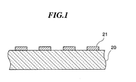
- FIG. 1 is a cross-sectional view of a glass substrate for displays according to an embodiment of the present invention.
- numeral 20 designates a glass substrate which has a top surface on which metal electrodes 21 are formed.
- Glass substrates which are employed for manufacturing glass substrates for displays by the manufacturing method according to an embodiment of the present invention are prepared by the float method.
- sheet glass is prepared by floating molten glass in a molten tin bath.
- a lower surface (bottom surface) of the glass substrate comes into contact with the molten tin bath, while an upper surface (top surface) of the glass substrate is exposed to a reducing atmosphere containing tin steam.
- a reducing heterogeneous layer (containing tin) having a thickness of at least 100 ⁇ m is formed on the bottom surface, and a reducing heterogeneous layer (containing tin) having a thickness of at least 5 ⁇ m is formed on the top surface.
- the sheet glass prepared as above is cut into a predetermined size to thereby produce glass substrates for displays.
- the top surface which has a smaller reducing heterogeneous layer thickness is a suitable surface for forming metal electrodes for displays.
- PDPs plasma displays
- a glass substrate for a front panel and a glass substrate for a back panel are arranged in opposed relation to each other, and then a metal paste of silver (Ag) or the like, and an insulating paste are applied to the inner surfaces of these glass substrates, followed by burning the inner surfaces, to thereby form metal electrodes of silver or the like, dielectric layers, partition walls, and fluorescent elements etc.
- a metal paste of silver (Ag) or the like, and an insulating paste are applied to the inner surfaces of these glass substrates, followed by burning the inner surfaces, to thereby form metal electrodes of silver or the like, dielectric layers, partition walls, and fluorescent elements etc.
- the glass substrate for the front panel and the glass substrate for the back panel are sealed together with a bonding glass having a low melting point, and then a mixed gas of xenon and a main discharge gas of neon is charged into the resulting display, followed by sealing the display in an airtight manner.
- the metal electrodes for example, silver electrodes
- the metal electrodes are formed as electrode films on the inner surfaces of the glass substrates by a film-forming method such as the screen printing method which is inexpensive.
- the silver component of the silver electrodes is reduced by the reducing heterogeneous layer (containing tin) of the surface of the glass substrate, as expressed by the following chemical formula, to form a colloidal metal.
- coloring occurs not just on the electrodes but also on their neighboring parts: 2Ag + + Sn 2+ ⁇ Ag(colloid) + Sn 4+
- the reducing heterogeneous layer formed on a surface of a glass substrate prepared by the the float process, on which silver electrodes are to be formed is removed by etching under conditions described below.
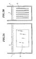
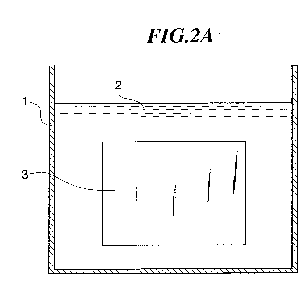
- FIGS. 2A and 2B are schematic views useful in explaining how glass substrates prepared by the float method are dipped in an etchant to remove reducing heterogeneous layers, according to an embodiment of the method of the present invention.
- reference numeral 1 designates a bath which is filled with an etchant 2 composed of a hydrofluoric acid solution.
- etchant 2 composed of a hydrofluoric acid solution.
- a plurality of glass substrates 3 which have been prepared by the float method are dipped in the etchant 2 in an erected fashion.
- the reducing heterogeneous layer of the glass substrate 3 it is preferable to remove the reducing heterogeneous layer of the glass substrate 3 by a depth of 5 to 14 ⁇ m, and more preferably by 6 to 11 ⁇ m, by the etching. If the depth is 5 ⁇ m or less, the entire reducing heterogeneous layer is not almost completely removed. On the other hand, even if the reducing heterogeneous layer is etched by more than 14 ⁇ m, the coloring suppressing effect is not further enhanced, and rather, the surface of the glass substrate 3 becomes rough, which is not desirable.
- a preferable temperature of the etchant 2 is between 10 to 30°C. It is preferable that the temperature of the etchant is high, since the etching rate increases so that the heterogeneous layer can be quickly removed by a desired amount. However, if the temperature exceeds 30°C, uneven etching is likely to occur on the the surface of the glass substrate 3 due to the surface of the glass substrate 3 being dried after the glass substrate 3 is taken out of the etchant 2.
- the etchant 2 is composed of a hydrofluoric acid solution having a hydrofluoric acid concentration of 1 to 25%.
- a preferable hydrofluoric acid etchant should contain at least one of a sulfuric acid solution, a nitric acid solution, or an acetic acid solution.
- the glass substrate 3 has a composition, by weight %, of 50 to 75% of SiO 2 , 10 to 27% of RO, 1 to 15% of A1203, and 2 to 15% of Na 2 O.
- SiO 2 acts as a network former for glass, and its preferable content is 50 to 75%. If the SiO 2 content is less than 50%, the glass has a lowered strain point, which leads to an increased heat contraction of the glass substrate during heat treatment of the manufacturing process of a plasma display, thereby unfavorably causing misregistration of patterns formed on the surface of the glass substrate 3. On the other hand, if the Si02 content is more than 75%, the glass substrate has a decreased thermal expansion coefficient so that warpage is prone to occur, since the substrate has a different thermal expansion coefficient with those of the insulating paste and a sealing frit etc. used in the display.
- RO MgO, CaO, SrO, BaO
- Its preferable content is 10 to 27%. If the RO (MgO, CaO, SrO, BaO) content is less than 10%, the glass has a lowered strain point so that the glass substrate becomes easy to be deformed during the plasma display manufacturing process. On the other hand, if the RO content is more than 27%, the glass becomes prone to devitrification and becomes difficult to be formed by the float method.
- A1203 acts to increase the strain point of the glass, and its preferable content is 1 to 15%. If the Al 2 O 3 content is less than 1%, the strain point becomes too low, whereas, if the Al 2 O 3 content is more than 15%, then the thermal expansion coefficient becomes too small.
- Na 2 O acts to adjust the thermal expansion coefficient. If its content is less than 2%, then the thermal expansion coefficient becomes too small, whereas, if the Na 2 O content is more than 15%, the strain point becomes too low.
- the glass may further contain other components in amounts which do not spoil the properties of the glass: specifically, ZrO 2 to improve the chemical durability of the glass, LiO 2 and K 2 O to adjust the thermal expansion coefficient, and Cl, SO 3 , SnO 2 , or the like as a defoaming agent.
- the reducing heterogeneous layer on the surface of the glass substrate 3 is removed by dipping the glass substrate in the etchant 2.
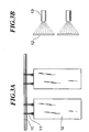
- an etchant may be sprayed by spraying nozzles 13 onto one surface of a glass substrate 12 suspended from a stationary support rod 10 by hangers 11.
- an etchant may be sprayed onto a top surface of a glass substrate 31 conveyed on rollers 30, by an etchant spraying header 32 provided above the rollers 30.
- This alternative embodiment can also obtain the same effects as those of the above described embodiment.
- Table 1 shows the compositions and properties of glass substrates A and B according to examples of the present invention.
- the glass substrates A and B in Table 1 were prepared from raw materials shown in Table 1 by mixing the raw materials so that compositions shown in Table 1 were obtained, then preparing from the mixed raw materials sheets of glass (sheet glass) having a thickness of 3mm by the float method, and then cutting the obtained sheets of glass into a size of 10mm in length and 10mm in width.
- the glass substrate A has a high strain point of 575°C, and when compared to the glass substrate B which has a strain point of 500°C, the glass substrate A shows a smaller heat contraction when subjected to a heat treatment.
- the glass substrates A and B are not prone to devitrification because the glasses both have a liquid-phase temperature of less than 1050°C.
- the glass substrates A and B show thermal expansion coefficient values falling within a range of 85 to 86 x 10 -7 /°C, which are commensurate with those of the insulating paste and sealing frit, which makes the substrates suitable for use in plasma display panels.
- strain point in Table 1 were obtained by measuring the strain point of the glass substrates A and B according to ASTM C336-71.
- the values of glass liquid-phase temperature were obtained by observation of the presence of devitrification after powders of the glasses having grain sizes of 297 to 500 ⁇ m were placed in a platinum boat and held in a temperature gradient furnace for 48 hours.
- the values of thermal expansion coefficient were obtained by measuring average values of thermal expansion coefficient of the glasses at temperatures between 30 to 380°C, using a dilatometer.
- the glass substrates A and B in Table 1 were each dipped in the etchant 2 within the etchant dipping apparatus shown in FIG. 2, to thereby remove the reducing heterogeneous layers on the bottom surface and the top surface of the glass substrates A and B.
- the concentration of hydrofluoric acid (HF concentration) of the etchant 2 was set to 50%, 25%, 10%, 2%, and 0.5% at a treatment temperature of 15°C, and to 25%, 10% and 2% at a treatment temperature 30°C.
- CONCENTRATION OF HF (%) TREATMENT TEMPERATURE (°C) ETCHING RATE ( ⁇ m/mm) RESULT OF ETCHING TREATMENT 50 15 72 STRONG REACTION 25 15 13 GOOD 10 15 2.2 GOOD 2 15 0.6 GOOD 0.5 15 0.05 LONG TREATMENT TIME 25 30 200 GOOD 10 30 30 GOOD 2 30 1.0 GOOD
- the results of the etching treatment were evaluated in terms of the etching rate ( ⁇ m/min) to obtain evaluation results as shown in Table 2. It can be seen from Table 2 that when the concentration of hydrofluoric acid is 50% (treatment temperature: 15°C) there occurs a strong reaction, and when the concentration is 0.5% (treatment temperature: 15°C) the treatment takes too much time. Therefore, the concentration of hydrofluoric acid is preferably within the range of 1 to 25%, and more preferably within 2 to 25%.
- a sulfuric acid solution may be added to a hydrofluoric acid solution.
- Table 3 shows results of etching treatments where sulfuric acid solutions of sulfuric acid concentrations of 50%, 20%, and 10% were added to hydrofluoric acid solutions of hydrofluoric acid concentrations of 0.5 to 25%.
- a nitric acid solution may be added to a hydrofluoric acid solution.
- Table 4 shows results of etching treatments where nitric acid solutions of nitric acid concentrations of 20% and 10% were added to hydrofluoric acid solutions of hydrofluoric acid concentrations of 0.5 to 25%.
- FIG. 5 shows results of a measurement of the concentration of tin (Sn) present in the vicinity of the top surface of the glass substrate B, using the secondary ion mass spectrometer (SIMS) method.
- SIMS secondary ion mass spectrometer
- tin is contained in an amount of 0.04 to 0.05 weight % in the surface of the glass substrate B, while at a depth of 6 ⁇ m from the surface, the tin content is 0.005 weight % (a value regarded as a "background level", which refers to the limit of detection of the analysis device), and can be considered that there is substantially no tin present.
- the degree of penetration and diffusion of tin into the glass substrate B is determined by factors such as the viscosity of the glass substrate B when placed in the molten tin bath of the sheet manufacturing device using the float method, the composition of the glass, and the amount of tin.
- each of the glass substrates Prior to etching the top surface, each of the glass substrates had its bottom surface coated with an adhesive film made of polyethylene, polypropylene or the like. Then, the glass substrates were subjected to etching.
- the bottom surface usually has numerous microscopic scratches which are invisible to the eyes, because the bottom surface is conveyed by rollers when passing through a cooling step or a cutting step after it is taken out of the molten tin bath of the sheet manufacturing device of the float method.
- the bottom surface by coating the bottom surface with the adhesive film, it is possible to prevent the microscopic scratches from increasing in both width and length when the scratches are etched with the hydrofluoric acid.
- the glass substrates are washed to peel away the adhesive film.
- the surfaces of the glass substrates A and B were etched to various depths using a hydrofluoric acid etchant of a hydrofluoric acid concentration of 5%. Then, on the surfaces which were etched, a silver paste having a width of approximately lmm was printed at intervals of approximately 1mm by the screen printing method, followed by a heat treatment at 550°C for 1 hour, to thereby form silver electrode films. The coloring conditions of the obtained glass substrates were observed.
- the degree of coloring was evaluated by looking through the glass substrate from the side on which the silver electrodes were not formed, to observe the coloring conditions of the silver electrodes.
- the results of the observation are represented by three levels, O (no coloring), ⁇ (slight coloring) and X (coloring), in which levels O and ⁇ refer to such levels that the glass substrates can be practically used for PDPs.
- the reducing heterogeneous layers formed on the glass substrates have an average thickness between 5 ⁇ m and 6 ⁇ m.
- a silver paste and an insulating paste were applied to the inner surfaces of these glass substrates, followed by burning the inner surfaces, to thereby form silver electrodes, dielectric layers, partition walls, and fluorescent elements etc.
- the glass substrates were sealed together with a bonding glass having a low melting point, and a mixed gas of xenon and a main discharge gas of neon were charged into the resulting display to thereby prepare a plasma display as a discharge testing device.
- the thus prepared testing device was operated, to obtain a picture image with excellent transparency and color balance.
Landscapes
- Chemical & Material Sciences (AREA)
- Life Sciences & Earth Sciences (AREA)
- Engineering & Computer Science (AREA)
- Chemical Kinetics & Catalysis (AREA)
- General Chemical & Material Sciences (AREA)
- Geochemistry & Mineralogy (AREA)
- Materials Engineering (AREA)
- Organic Chemistry (AREA)
- Surface Treatment Of Glass (AREA)
- Gas-Filled Discharge Tubes (AREA)
- Manufacture Of Electron Tubes, Discharge Lamp Vessels, Lead-In Wires, And The Like (AREA)
- Transforming Electric Information Into Light Information (AREA)
Abstract
Description
- The present invention relates to a method of manufacturing a glass substrate for displays and a glass substrate for displays manufactured by the same method.
- Glass substrates for displays for use in plasma display panels (PDPs), electron beam-excited display (including field emission displays (FEDs) and surface-conduction electron-emitter devices (SEDs)) or the like are made from sheet glass which is prepared by the float method. According to the float method, sheet glass is prepared by floating molten glass on a molten bath of tin, for example, which allows reliable and inexpensive mass production of a large-area sheet glass. Therefore, the float method is suitable for manufacturing glass substrates for displays such as PDPs and FEDs, which require a large display area of 40 inches, for example, in the case of PDPs, and are mass produced.
- During manufacture of sheet glass using the float method, the bottom surface (the lower surface of the sheet glass) comes into contact with the molten tin in the float bath, and the top surface (the upper surface of the sheet glass) is exposed to steam of the molten tin. Consequently, metal components penetrate as ions into the surface layers of both the bottom surface and the top surface, to form reducing heterogeneous layers.
- On the other hand, plasma displays (PDPs) are conventionally manufactured by the following method: First, a glass substrate for a front panel and a glass substrate for a back panel are arranged in opposed relation to each other, and then a metal paste of silver (Ag) or the like, and an insulating paste are applied to the inner surfaces of these glass substrates, followed by burning the inner surfaces, to thereby form metal electrodes of silver or the like, dielectric layers, partition walls, and fluorescent elements etc. Next, the glass substrate for the front panel and the glass substrate for the back panel are sealed together with a bonding glass having a low melting point, and then a mixed gas of xenon and a main discharge gas of neon are charged into the resulting display, followed by sealing the display in an airtight manner.
- In general, the metal electrodes, for example, silver electrodes, are formed as electrode films on the inner surfaces of the glass substrates by a film-forming method such as the screen printing method which is inexpensive. However, during the formation of the electrodes by this method, the silver component of the silver electrodes reacts with tin present in the reducing heterogeneous layers on the surfaces of the glass substrates, to form a colloidal metal. As a result, coloring occurs not just on the electrodes but also on their neighboring parts, which spoils the display performance of the plasma display in terms of transparency, color balance, etc.
- Therefore, conventionally, to prevent coloring from occurring during the formation of the silver electrode film, a SiO2 barrier layer is formed on the reducing heterogeneous layer by sputtering, CVD or the like, in order to suppress the effects of silver, or a glass substrate having a special glass composition is used which does not form a reducing heterogeneous layer during the manufacture of the sheet glass by the float method. However, the formation of the barrier layer has several problems: First, it does not only require equipment such as a sputtering device and a CVD device, resulting in a high manufacturing cost as well as a high maintenance cost, but also the barrier layer is not so reliable as to fully prevent coloring. Besides, the degree of adhesion of the barrier layer to the silver electrode is sometimes not sufficient. Further, when a glass substrate having a low alkali content, for example, is used as the above glass substrate having a special composition, further studies are required to obtain a suitable low-alkali composition and the glass matrix of the float furnace has to be changed accordingly, which results in a high manufacturing cost.
- Therefore, to prevent coloring, there has been usually employed a method of removing the reducing heterogeneous layer formed on the surface of the glass substrate prepared by the the float method, on which silver electrodes are to be formed, by grinding by approximately 10 to 100 µm using a grinding machine (e.g. Japanese Laid-Open Patent Publication (Kokai) No. 10-255669).
- Further, Japanese Laid-Open Patent Publication (Kokai) No. 10-144208 discloses a chemical grinding method as an alternative to the above mechanical grinding method, which removes the reducing heterogeneous layer (tin containing layer) of the glass surface by etching using a mixed aqueous solution of hydrogen peroxide and 1-hydrogen-2-ammonium fluoride.
- However, if the surface of the glass substrate is abraded by the above grinding machine, using cerium oxide as an abrasive, it takes at least 30 minutes to grind by 10µm, which is time consuming. Further, when an Oscar grinding machine is used, a grinding surface plate which is twice or more the size of the glass substrate to be abraded, is required. It is difficult to maintain the flatness of such large surface plate, and further, a central portion of the glass substrate is difficult to grind, while peripheral portions of the same is easy to grind, which makes it difficult to evenly grind the whole glass substrate.
- Also, the above chemical grinding method has the disadvantage that the rate at which the glass is ground by etching is so low, i.e., approximately 0.5 µm/min, that a considerable period of time is required to remove the reducing heterogeneous layer, thus being uneconomical. Further, hydrogen peroxide, which becomes active upon reaction, is used as the etchant, and therefore the etchant is not stable. In addition, a mixed aqueous solution of 1-hydrogen-2-ammonium fluoride is used as an alternative etchant, and hence a fluoride compound can be easily formed on the glass surface.
- It is therefore an object of the present invention to provide a method of manufacturing a glass substrate for displays, which is capable of allowing efficient and inexpensive removal of at least a reducing heterogeneous layer formed on the top surface of the glass substrate, and a glass substrate for displays manufactured by the same method.
- To attain the above object, the present invention provides a method of manufacturing a glass substrate for displays, comprising the steps of preparing a glass substrate having surfaces including an upper surface and a lower surface by a float method, and removing at least a reducing heterogeneous layer formed on the upper surface of the glass substrate, out of reducing heterogeneous layers formed on the surfaces of the glass substrate, by etching using an etchant which is mainly composed of hydrofluoric acid.
- Generally, during the formation of glass substrates by the float method, a reducing heterogeneous layer having a thickness of at least 100µm is formed on the bottom surface (lower surface of the glass substrate), and a reducing heterogeneous layer having a thickness of at least 5µm is formed on the top surface (upper surface of the glass substrate). The glass substrates are then cut into a predetermined size to thereby produce glass substrates for displays. Since the bottom surface of the substrate for displays has a larger reducing heterogeneous layer thickness, and further, can have more scratches and adherence of foreign matter, the top surface which has a smaller reducing heterogeneous layer thickness is used as the surface for forming metal electrodes for displays.
- According to the method of the present invention, it is possible to remove the reducing heterogeneous layer from at least the top surface of the glass substrate in an efficient manner without using a grinding machine, and the removal of the reducing heterogeneous layer requires simpler equipment than a grinding machine. Moreover, it is possible to easily change the depth of removal of the reducing heterogeneous layer.
- Preferably, the reducing heterogeneous layer is removed by a depth of 5 to 14µm.
- More preferably, the reducing heterogeneous layer is removed by a depth of 6 to 11µm.
- As a result, it is possible to completely remove the reducing heterogeneous layer in a reliable manner, and further, to positively prevent the surface of the glass substrate from becoming rough.
- In a preferred form of the present invention, the etching comprises dipping the glass substrate in the etchant.
- As a result, the reducing heterogeneous layer can be efficiently removed from the whole glass substrate by using simple etching equipment.
- Preferably, the etchant has a temperature between 10 to 30°C.
- As a result, uneven etching can be prevented while maintaining the etching rate at a suitable value.
- In a preferred form of the present invention, the etching comprises spraying the etchant at least on the upper surface of the glass substrate.
- As a result, the reducing heterogeneous layer from at least the upper surface of the glass substrate can be removed in an efficient manner using simple equipment.
- In a preferred form of the present invention, the method of manufacturing a glass substrate for displays further includes a step of coating the lower surface of the glass substrate with an adhesive film prior to the removing step, to thereby remove only the reducing heterogeneous layer formed on the upper surface of the glass substrate.
- As a result, microscopic scratches due to etching can be prevented from developing on the bottom surface, and further, the mechanical strength of the glass substrate can be prevented from lowering.
- Preferably, the etchant comprises a hydrofluoric acid solution having a hydrofluoric acid concentration of 1 to 25%.
- As a result, a drastic reaction can be prevented while maintaining the etching rate at a suitable value. In addition, it is possible to prevent the deterioration of the environment in which the equipment operates.
- In another preferred form of the present invention, the glass substrate has a composition, by weight %, of 50 to 75% of SiO2, 10 to 27% of RO, 1 to 15% of Al2O3, and 2 to 15% of Na2O.
- As a result, when the glass substrate is etched in a float bath, it can have flat planar surfaces, and the reducing heterogeneous layer can be removed while maintaining smooth surfaces of the glass substrate.
- Further, the present invention provides a glass substrate for displays manufactured by preparing a glass substrate having surfaces including an upper surface by a float method, and removing at least a reducing heterogeneous layer formed on the upper surface of the glass substrate, out of reducing heterogeneous layers formed on the surfaces of the glass substrate, by etching using an etchant which is mainly composed of hydrofluoric acid.
- As a result, it is possible to provide a glass substrate for displays which has a smooth and flat surface at a low cost.
- Preferably, only the reducing heterogeneous layer formed on the upper surface of the glass substrate is removed.
- As a result, it is possible to provide a glass substrate for displays which has only the reducing heterogeneous layer formed on the top surface removed.
- Preferably, the glass substrate has a composition, by weight %, of 50 to 75% of SiO2, 10 to 27% of RO, 1 to 15% of Al2O3, and 2 to 15% of Na2O.
- As a result, when the glass substrate is etched in a float bath, it can have flat planar surfaces, and the reducing heterogeneous layer can be removed while maintaining smooth surfaces of the glass substrate.
- Further, a glass substrate for displays according to the present invention manufactured by the above method is used for plasma display panels.
- As a result, it is possible to provide a glass substrate suitable for use in plasma display panels.
- The above and other objects, features and advantages of the invention will become more apparent from the following detailed description taken in conjunction with the accompanying drawings.
-
- FIG. 1 is a cross-sectional view of a glass substrate for displays according to an embodiment of the present invention;
- FIGS. 2A and 2B are schematic views useful in explaining how glass substrates prepared by the float method are dipped in an etchant to remove reducing heterogeneous layers, according to an embodiment of the method of the present invention, in which:
- FIG. 2A is an axial sectional view showing the configuration of an etchant dipping apparatus; and;
- FIG. 2B is a transverse sectional view showing the configuration of the same apparatus;
- FIGS. 3A and 3B are schematic views useful in explaining how glass substrates prepared by the float method are sprayed with an etchant to remove reducing heterogeneous layers, according to another embodiment of the method of the present invention, in which:
- FIG. 3A is a view showing the glass substrates suspended from a support rod of an etchant spraying apparatus; and
- FIG. 3B is a view showing the glass substrates and spray nozzles;
- FIG. 4 is a schematic view useful in explaining how glass substrates prepared by the float method are sprayed with an etchant to remove reducing heterogeneous layers, according to still another embodiment of the method of the present invention; and
- FIG. 5 is a graph showing results of a measurement of the concentration of tin (Sn) present in the vicinity of a top surface of a glass substrate B, using the secondary ion mass spectrometer (SIMS) method.
-
- The present invention will now be described in detail with reference to the drawings showing preferred embodiments thereof.
- To attain the above object, the present inventors conducted extensive studies and reached a finding that if, out of reducing heterogeneous layers formed on the surfaces of a glass substrate prepared by the float method, at least a reducing heterogeneous layer formed on the top surface of the glass substrate is removed by etching using an etchant which is mainly composed of hydrofluoric acid, it is possible to remove at least the reducing heterogeneous layer from the top surface of the glass substrate in an efficient manner without using a grinding machine, and the removal of the reducing heterogeneous layer requires simpler equipment than a grinding machine. Moreover, it was found that it is possible to easily change the depth of removal of the reducing heterogeneous layer.
- The present invention is based upon the above findings.
- The method of manufacturing a glass substrate for displays according to an embodiment of the present invention will now be described in detail with reference to the drawings.
- FIG. 1 is a cross-sectional view of a glass substrate for displays according to an embodiment of the present invention.
- In FIG. 1, numeral 20 designates a glass substrate which has a top surface on which
metal electrodes 21 are formed. - Glass substrates which are employed for manufacturing glass substrates for displays by the manufacturing method according to an embodiment of the present invention are prepared by the float method. According to the float method, sheet glass is prepared by floating molten glass in a molten tin bath. During the formation of the sheet glass by this float method, a lower surface (bottom surface) of the glass substrate comes into contact with the molten tin bath, while an upper surface (top surface) of the glass substrate is exposed to a reducing atmosphere containing tin steam. As a result, a reducing heterogeneous layer (containing tin) having a thickness of at least 100µm is formed on the bottom surface, and a reducing heterogeneous layer (containing tin) having a thickness of at least 5µm is formed on the top surface. The sheet glass prepared as above is cut into a predetermined size to thereby produce glass substrates for displays.
- Since the bottom surface of the above substrate for displays thus has a larger reducing heterogeneous layer thickness, and further, can have more scratches and adherence of foreign matter, it was found that the top surface which has a smaller reducing heterogeneous layer thickness is a suitable surface for forming metal electrodes for displays.
- On the other hand, as noted before, plasma displays (PDPs) are conventionally manufactured by the following method: First, a glass substrate for a front panel and a glass substrate for a back panel are arranged in opposed relation to each other, and then a metal paste of silver (Ag) or the like, and an insulating paste are applied to the inner surfaces of these glass substrates, followed by burning the inner surfaces, to thereby form metal electrodes of silver or the like, dielectric layers, partition walls, and fluorescent elements etc. Next, the glass substrate for the front panel and the glass substrate for the back panel are sealed together with a bonding glass having a low melting point, and then a mixed gas of xenon and a main discharge gas of neon is charged into the resulting display, followed by sealing the display in an airtight manner.
- As also noted before, in general, the metal electrodes, for example, silver electrodes, are formed as electrode films on the inner surfaces of the glass substrates by a film-forming method such as the screen printing method which is inexpensive. However, during the formation of the electrodes by this method, the silver component of the silver electrodes is reduced by the reducing heterogeneous layer (containing tin) of the surface of the glass substrate, as expressed by the following chemical formula, to form a colloidal metal. As a result, coloring occurs not just on the electrodes but also on their neighboring parts:
- This spoils the display performance of the plasma display in terms of transparency, color balance, etc.
- Therefore, according to the present embodiment, in order to prevent coloring during formation of the silver electrode film, the reducing heterogeneous layer formed on a surface of a glass substrate prepared by the the float process, on which silver electrodes are to be formed, is removed by etching under conditions described below.
- FIGS. 2A and 2B are schematic views useful in explaining how glass substrates prepared by the float method are dipped in an etchant to remove reducing heterogeneous layers, according to an embodiment of the method of the present invention.
- In FIGS. 2A and 2B, reference numeral 1 designates a bath which is filled with an
etchant 2 composed of a hydrofluoric acid solution. A plurality ofglass substrates 3 which have been prepared by the float method are dipped in theetchant 2 in an erected fashion. - It is preferable to remove the reducing heterogeneous layer of the
glass substrate 3 by a depth of 5 to 14µm, and more preferably by 6 to 11 µm, by the etching. If the depth is 5µm or less, the entire reducing heterogeneous layer is not almost completely removed. On the other hand, even if the reducing heterogeneous layer is etched by more than 14µm, the coloring suppressing effect is not further enhanced, and rather, the surface of theglass substrate 3 becomes rough, which is not desirable. - A preferable temperature of the
etchant 2 is between 10 to 30°C. It is preferable that the temperature of the etchant is high, since the etching rate increases so that the heterogeneous layer can be quickly removed by a desired amount. However, if the temperature exceeds 30°C, uneven etching is likely to occur on the the surface of theglass substrate 3 due to the surface of theglass substrate 3 being dried after theglass substrate 3 is taken out of theetchant 2. - It is preferable that the
etchant 2 is composed of a hydrofluoric acid solution having a hydrofluoric acid concentration of 1 to 25%. Also, a preferable hydrofluoric acid etchant should contain at least one of a sulfuric acid solution, a nitric acid solution, or an acetic acid solution. - Further, it is preferable that the
glass substrate 3 has a composition, by weight %, of 50 to 75% of SiO2, 10 to 27% of RO, 1 to 15% of A1203, and 2 to 15% of Na2O. - The reasons for limiting the composition of the
glass substrate 3 as above is as follows (hereinafter, % refers to weight %): - SiO2 acts as a network former for glass, and its preferable content is 50 to 75%. If the SiO2 content is less than 50%, the glass has a lowered strain point, which leads to an increased heat contraction of the glass substrate during heat treatment of the manufacturing process of a plasma display, thereby unfavorably causing misregistration of patterns formed on the surface of the
glass substrate 3. On the other hand, if the Si02 content is more than 75%, the glass substrate has a decreased thermal expansion coefficient so that warpage is prone to occur, since the substrate has a different thermal expansion coefficient with those of the insulating paste and a sealing frit etc. used in the display. - RO (MgO, CaO, SrO, BaO) facilitates the melting of the glass and also has the action of adjusting the thermal expansion coefficient of the same. Its preferable content is 10 to 27%. If the RO (MgO, CaO, SrO, BaO) content is less than 10%, the glass has a lowered strain point so that the glass substrate becomes easy to be deformed during the plasma display manufacturing process. On the other hand, if the RO content is more than 27%, the glass becomes prone to devitrification and becomes difficult to be formed by the float method.
- A1203 acts to increase the strain point of the glass, and its preferable content is 1 to 15%. If the Al2O3 content is less than 1%, the strain point becomes too low, whereas, if the Al2O3 content is more than 15%, then the thermal expansion coefficient becomes too small.
- Na2O acts to adjust the thermal expansion coefficient. If its content is less than 2%, then the thermal expansion coefficient becomes too small, whereas, if the Na2O content is more than 15%, the strain point becomes too low.
- In addition to the above components, the glass may further contain other components in amounts which do not spoil the properties of the glass: specifically, ZrO2 to improve the chemical durability of the glass, LiO2 and K2O to adjust the thermal expansion coefficient, and Cl, SO3, SnO2, or the like as a defoaming agent.
- In the above described embodiment, the reducing heterogeneous layer on the surface of the
glass substrate 3 is removed by dipping the glass substrate in theetchant 2. However, as shown in FIG. 3, an etchant may be sprayed by sprayingnozzles 13 onto one surface of aglass substrate 12 suspended from astationary support rod 10 byhangers 11. Even this alternative embodiment can obtain the same effects as those of the above described embodiment. - Further, as shown in FIG. 4, an etchant may be sprayed onto a top surface of a
glass substrate 31 conveyed onrollers 30, by anetchant spraying header 32 provided above therollers 30. This alternative embodiment can also obtain the same effects as those of the above described embodiment. - Next, examples of the present invention will be explained.
- Table 1 shows the compositions and properties of glass substrates A and B according to examples of the present invention.
COMPOSITION GLASS SUBSTRATE A GLASS SUBSTRATE B SiO2 59.0 73.0 Al2O3 6.0 1.5 MgO 2.5 4.1 CaO 6.5 7.4 SrO 7.5 - BaO 5.5 - Na2O 4.5 13.2 K2O 8.5 0.8 STRAIN POINT (°C) 575 500 THERMAL EXPANSION COEFFICIENT (× 10-7/°C) 85 86 LIQUID-PHASE TEMPERATURE (°C) 920 940 - The glass substrates A and B in Table 1 were prepared from raw materials shown in Table 1 by mixing the raw materials so that compositions shown in Table 1 were obtained, then preparing from the mixed raw materials sheets of glass (sheet glass) having a thickness of 3mm by the float method, and then cutting the obtained sheets of glass into a size of 10mm in length and 10mm in width.
- The glass substrate A has a high strain point of 575°C, and when compared to the glass substrate B which has a strain point of 500°C, the glass substrate A shows a smaller heat contraction when subjected to a heat treatment. The glass substrates A and B are not prone to devitrification because the glasses both have a liquid-phase temperature of less than 1050°C. The glass substrates A and B show thermal expansion coefficient values falling within a range of 85 to 86 x 10-7/°C, which are commensurate with those of the insulating paste and sealing frit, which makes the substrates suitable for use in plasma display panels.
- The values of strain point in Table 1 were obtained by measuring the strain point of the glass substrates A and B according to ASTM C336-71. The values of glass liquid-phase temperature were obtained by observation of the presence of devitrification after powders of the glasses having grain sizes of 297 to 500 µm were placed in a platinum boat and held in a temperature gradient furnace for 48 hours. Further, the values of thermal expansion coefficient were obtained by measuring average values of thermal expansion coefficient of the glasses at temperatures between 30 to 380°C, using a dilatometer.
- Next, the glass substrates A and B in Table 1 were each dipped in the
etchant 2 within the etchant dipping apparatus shown in FIG. 2, to thereby remove the reducing heterogeneous layers on the bottom surface and the top surface of the glass substrates A and B. - In the examples of the present invention, as shown in Table 2, the concentration of hydrofluoric acid (HF concentration) of the
etchant 2 was set to 50%, 25%, 10%, 2%, and 0.5% at a treatment temperature of 15°C, and to 25%, 10% and 2% at atreatment temperature 30°C.CONCENTRATION OF HF (%) TREATMENT TEMPERATURE (°C) ETCHING RATE (µm/mm) RESULT OF ETCHING TREATMENT 50 15 72 STRONG REACTION 25 15 13 GOOD 10 15 2.2 GOOD 2 15 0.6 GOOD 0.5 15 0.05 LONG TREATMENT TIME 25 30 200 GOOD 10 30 30 GOOD 2 30 1.0 GOOD - The results of the etching treatment were evaluated in terms of the etching rate (µm/min) to obtain evaluation results as shown in Table 2. It can be seen from Table 2 that when the concentration of hydrofluoric acid is 50% (treatment temperature: 15°C) there occurs a strong reaction, and when the concentration is 0.5% (treatment temperature: 15°C) the treatment takes too much time. Therefore, the concentration of hydrofluoric acid is preferably within the range of 1 to 25%, and more preferably within 2 to 25%.
- For the
etchant 2, a sulfuric acid solution may be added to a hydrofluoric acid solution. Table 3 shows results of etching treatments where sulfuric acid solutions of sulfuric acid concentrations of 50%, 20%, and 10% were added to hydrofluoric acid solutions of hydrofluoric acid concentrations of 0.5 to 25%.CONCENTRATION (%) TREATMENT TEMPERATURE (°C) ETCHING RATE (µm/min) RESULT OF ETCHING TREATMENT HF H2SO4 25 50 15 11 GOOD 10 50 15 2 GOOD 2 50 15 0.8 GOOD 0.5 50 15 0.1 GOOD 25 20 15 10 GOOD 10 20 15 2 GOOD 2 20 15 0.9 GOOD 0.5 20 15 0.1 GOOD 25 10 15 10 GOOD 10 10 15 2 GOOD 2 10 15 0.3 GOOD 0.5 10 15 0.1 GOOD - In each case, it was possible to substantially remove the tin while maintaining a smooth surface.
- Further, for the
etchant 2, a nitric acid solution may be added to a hydrofluoric acid solution. Table 4 shows results of etching treatments where nitric acid solutions of nitric acid concentrations of 20% and 10% were added to hydrofluoric acid solutions of hydrofluoric acid concentrations of 0.5 to 25%.CONCENTRATION (%) TREATMENT TEMPERATURE (°C) ETCHING RATE (µm/min) RESULT OF ETCHING TREATMENT HF H2SO4 25 20 15 9 GOOD 10 20 15 2 GOOD 2 20 15 0.9 GOOD 0.5 20 15 0.1 GOOD 25 10 15 9 GOOD 10 10 15 3 GOOD 2 10 15 1 GOOD 0.5 10 15 0.1 GOOD - In each case, it was possible to substantially remove the tin while maintaining a smooth surface.
- FIG. 5 shows results of a measurement of the concentration of tin (Sn) present in the vicinity of the top surface of the glass substrate B, using the secondary ion mass spectrometer (SIMS) method.
According to the SIMS method, an analysis of the composition is performed by counting the number of Na ions while the surface of the glass substrate is cut by sputtering with argon. - It can be seen from FIG. 5 that tin is contained in an amount of 0.04 to 0.05 weight % in the surface of the glass substrate B, while at a depth of 6µm from the surface, the tin content is 0.005 weight % (a value regarded as a "background level", which refers to the limit of detection of the analysis device), and can be considered that there is substantially no tin present. The degree of penetration and diffusion of tin into the glass substrate B is determined by factors such as the viscosity of the glass substrate B when placed in the molten tin bath of the sheet manufacturing device using the float method, the composition of the glass, and the amount of tin.
- Prior to etching the top surface, each of the glass substrates had its bottom surface coated with an adhesive film made of polyethylene, polypropylene or the like. Then, the glass substrates were subjected to etching. The bottom surface usually has numerous microscopic scratches which are invisible to the eyes, because the bottom surface is conveyed by rollers when passing through a cooling step or a cutting step after it is taken out of the molten tin bath of the sheet manufacturing device of the float method. However, by coating the bottom surface with the adhesive film, it is possible to prevent the microscopic scratches from increasing in both width and length when the scratches are etched with the hydrofluoric acid.
- After etching, the glass substrates are washed to peel away the adhesive film.
- Next, the surfaces of the glass substrates A and B were etched to various depths using a hydrofluoric acid etchant of a hydrofluoric acid concentration of 5%. Then, on the surfaces which were etched, a silver paste having a width of approximately lmm was printed at intervals of approximately 1mm by the screen printing method, followed by a heat treatment at 550°C for 1 hour, to thereby form silver electrode films. The coloring conditions of the obtained glass substrates were observed.
- The relationship between the depth of removal of the surface by etching and the coloring of the silver electrodes of each glass substrate is shown in Table 5.
DEPTH FROM SURFACE
(µm)GLASS SUBSTRATE A GLASS SUBSTRATE B 2 COLORING IN RUSSET × COLORING IN RUSSET × 5 NO COLORING O LIGHT BROWN COLORING Δ 6 NO COLORING O NO COLORING O 11 NO COLORING O NO COLORING O 14 NO COLORING O NO COLORING O 17 NO COLORING O NO COLORING O - The degree of coloring was evaluated by looking through the glass substrate from the side on which the silver electrodes were not formed, to observe the coloring conditions of the silver electrodes. The results of the observation are represented by three levels, O (no coloring), Δ (slight coloring) and X (coloring), in which levels O and Δ refer to such levels that the glass substrates can be practically used for PDPs.
- According to Table 5, it is learned that when the glass substrates A and B were etched so that a depth of 6µm or more was removed, neither of the substrates showed coloring ; the glass substrate A did not show coloring when removed by a depth of 5 µm, however, the glass substrate B showed slight coloring when removed by the same depth, and when the surfaces were removed by a depth of 2µm, both the glass substrates A and B showed distinct coloring.
- It can be gathered from these data that the reducing heterogeneous layers formed on the glass substrates have an average thickness between 5µm and 6µm.
- Further, the glass substrates A and B in Table 1, which were etched on the top surfaces to remove a depth of 6µm, were then arranged in opposed relation to each other with the top surfaces facing inward. Next, a silver paste and an insulating paste were applied to the inner surfaces of these glass substrates, followed by burning the inner surfaces, to thereby form silver electrodes, dielectric layers, partition walls, and fluorescent elements etc. Then, the glass substrates were sealed together with a bonding glass having a low melting point, and a mixed gas of xenon and a main discharge gas of neon were charged into the resulting display to thereby prepare a plasma display as a discharge testing device.
- Then, the thus prepared testing device was operated, to obtain a picture image with excellent transparency and color balance.
Claims (13)
- A method of manufacturing a glass substrate for displays, comprising the steps of:preparing a glass substrate having surfaces including an upper surface and a lower surface by a float method; andremoving at least a reducing heterogeneous layer formed on the upper surface of said glass substrate, out of reducing heterogeneous layers formed on the surfaces of said glass substrate, by etching using an etchant which is mainly composed of hydrofluoric acid.
- A method as claimed in claim 1, wherein said reducing heterogeneous layer is removed by a depth of 5 to 14µm.
- A method as claimed in claim 2, wherein said reducing heterogeneous layer is removed by a depth of 6 to 11µm.
- A method as claimed in any of claims 1 to 3, wherein said etching comprises dipping said glass substrate in said etchant.
- A method as claimed in claim 4, wherein said etchant has a temperature between 10 to 30°C.
- A method as claimed in any of claims 1 to 3, wherein said etching comprises spraying said etchant at least on the upper surface of said glass substrate.
- A method as claimed in any of claims 1 to 6, further including a step of coating the lower surface of said glass substrate with an adhesive film prior to said removing step, to thereby remove only the reducing heterogeneous layer formed on the upper surface of said glass substrate.
- A method as claimed in any of claims 1 to 7, wherein said etchant comprises a hydrofluoric acid solution having a hydrofluoric acid concentration of 1 to 25%.
- A method as claimed in any of claims 1 to 8, wherein said glass substrate has a composition, by weight %, of 50 to 75% of SiO2, 10 to 27% of RO, 1 to 15% of Al2O3, and 2 to 15% of Na2O.
- A glass substrate for displays manufactured by preparing a glass substrate having surfaces including an upper surface by a float method, and removing at least a reducing heterogeneous layer formed on the upper surface of said glass substrate, out of reducing heterogeneous layers formed on the surfaces of said glass substrate, by etching using an etchant which is mainly composed of hydrofluoric acid.
- A glass substrate for displays as claimed in claim 10, wherein only the reducing heterogeneous layer formed on the upper surface of said glass substrate is removed.
- A glass substrate for displays as claimed in claim 10 or 11, wherein said glass substrate has a composition, by weight %, of 50 to 75% of Si02, 10 to 27% of RO, 1 to 15% of Al2O3, and 2 to 15% of Na2O.
- A glass substrate for displays as claimed in any of claims 10 to 12, which is used for plasma display panels.
Applications Claiming Priority (2)
| Application Number | Priority Date | Filing Date | Title |
|---|---|---|---|
| JP27199799 | 1999-09-27 | ||
| JP27199799A JP2001089191A (en) | 1999-09-27 | 1999-09-27 | Method of manufacturing glass substrate for display and glass substrate for display manufactured by the manufacturing method |
Publications (1)
| Publication Number | Publication Date |
|---|---|
| EP1086931A1 true EP1086931A1 (en) | 2001-03-28 |
Family
ID=17507720
Family Applications (1)
| Application Number | Title | Priority Date | Filing Date |
|---|---|---|---|
| EP00402646A Withdrawn EP1086931A1 (en) | 1999-09-27 | 2000-09-25 | Method of manufacturing a glass substrate for displays and a glass substrate for displays manufactured by same |
Country Status (6)
| Country | Link |
|---|---|
| US (1) | US20030205558A1 (en) |
| EP (1) | EP1086931A1 (en) |
| JP (1) | JP2001089191A (en) |
| KR (1) | KR20010070107A (en) |
| CN (1) | CN1297219A (en) |
| TW (1) | TW480514B (en) |
Cited By (4)
| Publication number | Priority date | Publication date | Assignee | Title |
|---|---|---|---|---|
| WO2003018501A1 (en) * | 2001-08-31 | 2003-03-06 | Stella Chemifa Kabushiki Kaisha | Surface treating fluid for fine processing of multi-component glass substrate |
| WO2003105181A1 (en) * | 2002-06-11 | 2003-12-18 | 株式会社 東芝 | Image display device and method of producing the device |
| SG121817A1 (en) * | 2002-11-22 | 2006-05-26 | Nishiyama Stainless Chemical Co Ltd | Glass substrate for flat planel display, and process for producing the same |
| EP2463244A4 (en) * | 2009-08-07 | 2013-03-06 | Lg Chemical Ltd | Electrically conductive base plate and a production method for the same |
Families Citing this family (19)
| Publication number | Priority date | Publication date | Assignee | Title |
|---|---|---|---|---|
| JP4264927B2 (en) * | 2002-08-26 | 2009-05-20 | 株式会社日立プラズマパテントライセンシング | Manufacturing method of substrate for thin display device |
| JP2006113142A (en) * | 2004-10-12 | 2006-04-27 | Nippon Sheet Glass Co Ltd | Glass optical elemental and its manufacturing method |
| MXGT04000020A (en) * | 2004-12-10 | 2005-06-07 | Luis Rendon Granados Juan | Chemical process for a satin-partial or complete unpolished glass by immersion in an acid solution for simultaneously and continuously producing one or several pieces and/or sheets of glass, the same having standard and variable dimensions. |
| JP2006306656A (en) * | 2005-04-28 | 2006-11-09 | Nitta Ind Corp | Protective tape for etching and method for etching glass substrate |
| JP4794982B2 (en) * | 2005-10-27 | 2011-10-19 | 古河電気工業株式会社 | Manufacturing method of glass strip |
| JP4417926B2 (en) | 2006-03-06 | 2010-02-17 | カシオ計算機株式会社 | Method for flattening glass substrate |
| JP4324742B2 (en) * | 2006-04-28 | 2009-09-02 | シャープ株式会社 | Manufacturing method of polished glass substrate |
| CN101484838B (en) * | 2006-06-30 | 2011-11-02 | 旭硝子株式会社 | Liquid crystal display panel |
| CN101190038B (en) * | 2006-12-01 | 2010-12-08 | 邝少丹 | Method for producing passiflora edulis vinegar beverage |
| KR20090110863A (en) * | 2007-02-01 | 2009-10-22 | 윌라드 앤드 켈시 솔라 그룹, 엘엘씨 | Systems and Methods for Glass Sheet Semiconductor Coatings |
| TWI418523B (en) * | 2007-11-05 | 2013-12-11 | Photo Jet Internat Co Ltd | Surface treatment systems for glass |
| US9434644B2 (en) * | 2010-09-30 | 2016-09-06 | Avanstrate Inc. | Cover glass and method for producing cover glass |
| JP5835654B2 (en) * | 2011-08-31 | 2015-12-24 | 日本電気硝子株式会社 | Method for producing tempered glass substrate |
| WO2013101444A1 (en) * | 2011-12-30 | 2013-07-04 | Corning Incorporated | Media and methods for etching glass |
| JP5518133B2 (en) * | 2012-06-14 | 2014-06-11 | 株式会社Nsc | Chemical polishing equipment |
| CN103241958B (en) * | 2013-05-28 | 2016-05-04 | 湖北优尼科光电技术股份有限公司 | A kind of engraving method of LCD glass substrate |
| CN103241957B (en) * | 2013-05-28 | 2016-04-20 | 湖北优尼科光电技术股份有限公司 | A kind of thinning glass substrate engraving method |
| CN103922602A (en) * | 2014-04-04 | 2014-07-16 | 惠州市清洋实业有限公司 | TFT (thin film transistor) glass substrate reducer, preparation method thereof and TFT glass substrate reducing process |
| JP7520293B2 (en) * | 2021-03-17 | 2024-07-23 | 日本電気硝子株式会社 | Tempered glass sheet and method for producing the same |
Citations (5)
| Publication number | Priority date | Publication date | Assignee | Title |
|---|---|---|---|---|
| GB1019415A (en) * | 1963-01-23 | 1966-02-09 | Pittsburgh Plate Glass Co | Process for finishing float glass |
| JPH06227842A (en) * | 1993-02-01 | 1994-08-16 | Nippon Sheet Glass Co Ltd | Surface tin removal method for float glass products |
| JPH10144208A (en) | 1996-09-10 | 1998-05-29 | Dainippon Printing Co Ltd | Electrode formation method |
| JPH10255669A (en) | 1997-03-14 | 1998-09-25 | Nippon Electric Glass Co Ltd | Glass substrate for flat panel display and plasma display device using it |
| JPH11246238A (en) * | 1998-03-03 | 1999-09-14 | Mitsubishi Electric Corp | Plasma display panel and glass substrate for plasma display panel as well as their production |
Family Cites Families (5)
| Publication number | Priority date | Publication date | Assignee | Title |
|---|---|---|---|---|
| US3284181A (en) * | 1964-07-29 | 1966-11-08 | Pittsburgh Plate Glass Co | Process for finishing float glass |
| US3769113A (en) * | 1971-04-01 | 1973-10-30 | Conrad Schmitt Studios Inc | Method of etching glass |
| JPS5122490B2 (en) * | 1972-04-21 | 1976-07-10 | ||
| JP3144823B2 (en) * | 1991-04-26 | 2001-03-12 | 旭硝子株式会社 | Alkali-free glass |
| US5631195A (en) * | 1994-09-14 | 1997-05-20 | Asahi Glass Company Ltd. | Glass composition and substrate for plasma display |
-
1999
- 1999-09-27 JP JP27199799A patent/JP2001089191A/en active Pending
-
2000
- 2000-09-25 EP EP00402646A patent/EP1086931A1/en not_active Withdrawn
- 2000-09-26 TW TW089119841A patent/TW480514B/en not_active IP Right Cessation
- 2000-09-27 CN CN00129572A patent/CN1297219A/en active Pending
- 2000-09-27 KR KR1020000056708A patent/KR20010070107A/en not_active Withdrawn
-
2003
- 2003-04-30 US US10/426,357 patent/US20030205558A1/en not_active Abandoned
Patent Citations (5)
| Publication number | Priority date | Publication date | Assignee | Title |
|---|---|---|---|---|
| GB1019415A (en) * | 1963-01-23 | 1966-02-09 | Pittsburgh Plate Glass Co | Process for finishing float glass |
| JPH06227842A (en) * | 1993-02-01 | 1994-08-16 | Nippon Sheet Glass Co Ltd | Surface tin removal method for float glass products |
| JPH10144208A (en) | 1996-09-10 | 1998-05-29 | Dainippon Printing Co Ltd | Electrode formation method |
| JPH10255669A (en) | 1997-03-14 | 1998-09-25 | Nippon Electric Glass Co Ltd | Glass substrate for flat panel display and plasma display device using it |
| JPH11246238A (en) * | 1998-03-03 | 1999-09-14 | Mitsubishi Electric Corp | Plasma display panel and glass substrate for plasma display panel as well as their production |
Non-Patent Citations (2)
| Title |
|---|
| DATABASE WPI Section Ch Week 199437, Derwent World Patents Index; Class L01, AN 1994-299572, XP002155758 * |
| DATABASE WPI Section Ch Week 199948, Derwent World Patents Index; Class L03, AN 1999-566334, XP002155757 * |
Cited By (4)
| Publication number | Priority date | Publication date | Assignee | Title |
|---|---|---|---|---|
| WO2003018501A1 (en) * | 2001-08-31 | 2003-03-06 | Stella Chemifa Kabushiki Kaisha | Surface treating fluid for fine processing of multi-component glass substrate |
| WO2003105181A1 (en) * | 2002-06-11 | 2003-12-18 | 株式会社 東芝 | Image display device and method of producing the device |
| SG121817A1 (en) * | 2002-11-22 | 2006-05-26 | Nishiyama Stainless Chemical Co Ltd | Glass substrate for flat planel display, and process for producing the same |
| EP2463244A4 (en) * | 2009-08-07 | 2013-03-06 | Lg Chemical Ltd | Electrically conductive base plate and a production method for the same |
Also Published As
| Publication number | Publication date |
|---|---|
| JP2001089191A (en) | 2001-04-03 |
| US20030205558A1 (en) | 2003-11-06 |
| TW480514B (en) | 2002-03-21 |
| CN1297219A (en) | 2001-05-30 |
| KR20010070107A (en) | 2001-07-25 |
Similar Documents
| Publication | Publication Date | Title |
|---|---|---|
| US20030205558A1 (en) | Method of manufacturing a glass substrate for displays and a glass substrate for displays manufactured by same | |
| KR100807928B1 (en) | Plasma Display Panel And Method Of Manufacturing The Same | |
| US7884547B2 (en) | Lead-free acid-resistant glass composition and glass paste comprised of the same | |
| US7326666B2 (en) | Glass for forming barrier ribs, and plasma display panel | |
| US20110015053A1 (en) | Lead-Free Low-Melting-Point Glass Composition Having Acid Resistance | |
| US6500778B1 (en) | Glass substrate for a display | |
| KR20150067091A (en) | Glass Etching Media and Methods | |
| US20070236147A1 (en) | Glass for covering electrodes, electric wiring-formed glass plate and plasma display device | |
| KR20010078017A (en) | Glass article and glass substrate for display panel | |
| US20170144923A1 (en) | Removal of inorganic coatings from glass substrates | |
| JPH10255669A (en) | Glass substrate for flat panel display and plasma display device using it | |
| JP4158249B2 (en) | Method for producing glass for display substrate by float method | |
| KR20020034925A (en) | Glass for covering electrodes and plasma display panel | |
| KR20170121081A (en) | Glass sheet, glass substrate for display, and glass substrate for solar cell | |
| JP2000226233A (en) | Float glass for flat panel display substrates | |
| JP4273566B2 (en) | Float glass for display substrates | |
| US7744439B2 (en) | Image display device and manufacturing method of the same | |
| KR20090083328A (en) | Bulkhead forming material for plasma display panel and glass composition for bulkhead forming material | |
| US20060068209A1 (en) | Glass plate for display substrate | |
| JPH11246238A (en) | Plasma display panel and glass substrate for plasma display panel as well as their production | |
| JP2007204295A (en) | Glass plate for display substrate and manufacturing method thereof | |
| JP2000169180A (en) | Float glass for display substrate | |
| KR100643043B1 (en) | Evaluation method of an image display apparatus and the glass substrate used for it | |
| KR100620420B1 (en) | Manufacturing method of glass substrate for image display device | |
| JP2004182577A (en) | Glass for flat panel display substrate and flat panel display substrate |
Legal Events
| Date | Code | Title | Description |
|---|---|---|---|
| PUAI | Public reference made under article 153(3) epc to a published international application that has entered the european phase |
Free format text: ORIGINAL CODE: 0009012 |
|
| AK | Designated contracting states |
Kind code of ref document: A1 Designated state(s): DE FR GB |
|
| AX | Request for extension of the european patent |
Free format text: AL;LT;LV;MK;RO;SI |
|
| 17P | Request for examination filed |
Effective date: 20010615 |
|
| AKX | Designation fees paid |
Free format text: DE FR GB |
|
| 17Q | First examination report despatched |
Effective date: 20020503 |
|
| APBN | Date of receipt of notice of appeal recorded |
Free format text: ORIGINAL CODE: EPIDOSNNOA2E |
|
| APBR | Date of receipt of statement of grounds of appeal recorded |
Free format text: ORIGINAL CODE: EPIDOSNNOA3E |
|
| APAA | Appeal reference recorded |
Free format text: ORIGINAL CODE: EPIDOS REFN |
|
| APBT | Appeal procedure closed |
Free format text: ORIGINAL CODE: EPIDOSNNOA9E |
|
| APAF | Appeal reference modified |
Free format text: ORIGINAL CODE: EPIDOSCREFNE |
|
| STAA | Information on the status of an ep patent application or granted ep patent |
Free format text: STATUS: THE APPLICATION HAS BEEN WITHDRAWN |
|
| 18W | Application withdrawn |
Effective date: 20050818 |