EP1086917A1 - A sheet deposition device for selective deposition of sheets on superposed supports - Google Patents
A sheet deposition device for selective deposition of sheets on superposed supports Download PDFInfo
- Publication number
- EP1086917A1 EP1086917A1 EP00202859A EP00202859A EP1086917A1 EP 1086917 A1 EP1086917 A1 EP 1086917A1 EP 00202859 A EP00202859 A EP 00202859A EP 00202859 A EP00202859 A EP 00202859A EP 1086917 A1 EP1086917 A1 EP 1086917A1
- Authority
- EP
- European Patent Office
- Prior art keywords
- support
- deposition
- sheet
- detection signal
- sheets
- Prior art date
- Legal status (The legal status is an assumption and is not a legal conclusion. Google has not performed a legal analysis and makes no representation as to the accuracy of the status listed.)
- Granted
Links
- 230000008021 deposition Effects 0.000 title claims abstract description 180
- 238000001514 detection method Methods 0.000 claims abstract description 62
- 230000004044 response Effects 0.000 claims abstract description 16
- 230000004913 activation Effects 0.000 claims abstract description 12
- 238000006073 displacement reaction Methods 0.000 claims description 9
- 230000000694 effects Effects 0.000 description 5
- 230000001681 protective effect Effects 0.000 description 3
- 238000011144 upstream manufacturing Methods 0.000 description 3
- 230000008901 benefit Effects 0.000 description 2
- 230000008859 change Effects 0.000 description 2
- 238000010276 construction Methods 0.000 description 2
- 238000007373 indentation Methods 0.000 description 2
- XAGFODPZIPBFFR-UHFFFAOYSA-N aluminium Chemical compound [Al] XAGFODPZIPBFFR-UHFFFAOYSA-N 0.000 description 1
- 229910052782 aluminium Inorganic materials 0.000 description 1
- 239000004411 aluminium Substances 0.000 description 1
- 238000010586 diagram Methods 0.000 description 1
- 230000007246 mechanism Effects 0.000 description 1
- 238000000926 separation method Methods 0.000 description 1
- 239000000725 suspension Substances 0.000 description 1
Images


Classifications
-
- B—PERFORMING OPERATIONS; TRANSPORTING
- B65—CONVEYING; PACKING; STORING; HANDLING THIN OR FILAMENTARY MATERIAL
- B65H—HANDLING THIN OR FILAMENTARY MATERIAL, e.g. SHEETS, WEBS, CABLES
- B65H31/00—Pile receivers
- B65H31/24—Pile receivers multiple or compartmented, e.d. for alternate, programmed, or selective filling
-
- B—PERFORMING OPERATIONS; TRANSPORTING
- B65—CONVEYING; PACKING; STORING; HANDLING THIN OR FILAMENTARY MATERIAL
- B65H—HANDLING THIN OR FILAMENTARY MATERIAL, e.g. SHEETS, WEBS, CABLES
- B65H2408/00—Specific machines
- B65H2408/10—Specific machines for handling sheet(s)
- B65H2408/11—Sorters or machines for sorting articles
- B65H2408/113—Sorters or machines for sorting articles with variable location in space of the bins relative to a stationary in-feed path
- B65H2408/1131—Sorters or machines for sorting articles with variable location in space of the bins relative to a stationary in-feed path and variable bin capacity
-
- B—PERFORMING OPERATIONS; TRANSPORTING
- B65—CONVEYING; PACKING; STORING; HANDLING THIN OR FILAMENTARY MATERIAL
- B65H—HANDLING THIN OR FILAMENTARY MATERIAL, e.g. SHEETS, WEBS, CABLES
- B65H2801/00—Application field
- B65H2801/03—Image reproduction devices
- B65H2801/06—Office-type machines, e.g. photocopiers
Definitions
- the invention relates to a sheet deposition device for the selective deposition of printed sheets on a number of superposed supports wherein each support is provided with its own drive means for moving said support up and down between a deposition position in which sheets can be deposited on that support and a parking position in which sheet deposition is not possible.
- a sheet deposition device of this kind is known from European Patent 0 532 069.
- a change-over can be made to further deposition of sheets on one of the other supports, provided there are no sheets present on said other support, and this can be detected by a detector at the support surface of a support.
- the object of the invention is to provide a sheet deposition device wherein a support is movable between the deposition position and the parking position provided that there is still free space for movement between the superposed supports and without the supports, possibly with sheets therebetween, jamming against one another.
- a support is provided with detection means for detecting an obstacle in the space directly therebeneath, for example sheets on a support directly therebeneath, which detection means deliver a first detection signal when the distance between the support provided with said detection means and an obstacle therebeneath is greater than a predetermined amount and deliver a second detection signal when said distance is equal to said predetermined amount and the sheet deposition device comprises a control device which in response to reception of a first detection signal makes the drive means capable of activation for moving towards one another the supports between which are situated the detection means delivering the first detection signal and which deactivate the said drive means in response to the reception of a second detection signal.
- the detection means comprises a flat plate suspended beneath a support and movable between a first position in which the plate is situated at some distance from and parallel to said support and a second position in which the plate is situated at an even shorter distance from said support and the detection means further comprise switching means between the plate and the support with actuating means which are rigidly connected to the movable plate and in the first position of the plate actuate the switching means to deliver the first detection signal and in the second position of the plate actuate the switching means to deliver the second detection signal.
- the effect of the flat plate is that an obstacle beneath a support can be detected over a relatively large range, this being important particularly if the object is a stack of sheets on a support situated directly beneath the relevant support, which stack does not have a flat top, for example because the stack consists of stapled sets which have a relatively considerable thickness at the staple location.
- the plate is provided with fixing means near opposite edges, which fixing means connect the plate to the support for movement in the vertical direction and switching means are provided at each of said fixing means.
- one of the detecting means further comprises a U-shaped strap, of which the intermediate piece connecting its limbs is connected for rotation about its longitudinal axis to one of the plates or supports for connection and the ends of the limbs are rotatably connected to the other plate or support for connection.
- the effect of this is that during its movement from the first position to the second position the plate can tip in only one direction so that for the detection of an obstacle up to the four corner points of the plate it is only necessary to use two switching means near the fixing points in a central zone of the plate.
- control device of the sheet deposition device comprises control means which in response to the reception of a first detection signal delivered by the detection means at a support in a deposition position or a support therebeneath make the drive means of said supports capable of activation for moving said support(s) downwards on deposition of following sheets on said support.
- control device comprises control means which, on displacement of a support from a parking position to its deposition position and in response to the reception of a first detection signal delivered by the detection at another support situated between the said parking position and the deposition position, make the drive means of said other support or supports capable of activation for joint downward or upward movement with the support to be displaced into its deposition position.
- the printing apparatus 1 shown in Fig. 1 comprises means known per se for printing an image on a receiving sheet. These images for printing may be present on original documents which are fed to a scanning station 2 situated at the top of the printing apparatus 1. Images for printing can also be fed in digital form from a workstation 3 connected via a network 4 to a control device 8 of the printing apparatus 1. A printing cycle for copying a set of originals presented via the scanning station 2 is started by actuating a start button 6 on the operator control panel 5 of the printing apparatus 1.
- a printing cycle for printing a set of images presented via workstation 3 can be started by actuating a start button 7 provided on the workstation 3, via control device 8 (hereinafter referred to as automatic printing), or by actuating a start button 6 provided on the operator control panel 5 of the printing apparatus 1 (hereinafter referred to as semi-automatic printing).
- the sheet transport path 10 forms the path for delivering to a sheet finishing station 11 the sheets printed in the printing apparatus.
- the finishing station 11 contains a sheet collecting tray 12 (not shown in detail) in which a number of printed sheets belonging to a set can be collected and stapled, whereafter discharge roller pairs 13 feed the set of printed sheets to a sheet deposition unit 15 forming part of a sheet deposition station 11.
- the sheet deposition unit 15 comprises four superposed deposition tables 16, 17, 18 and 19, each of which can be set to a deposition position with respect to the horizontal discharge path formed by the discharge roller pair 13, to receive sheets discharged by the discharge roller pair 13.
- the vertical displacement of the deposition tables can be effected by means of the displacement mechanism described in European Patent Specification 0 532 069, the selected deposition table or the sheet at the top thereof always lying just beneath the discharge path formed by the discharge roller pair 13.
- Fig. 1 shows the bottom deposition table 16 in a bottom deposition position in which a maximum number of sheets is situated on said deposition table 16 and the deposition tables 17, 18 and 19 situated thereabove are in parking positions situated above the discharge path formed by the discharge roller pair 13.
- the deposition tables 17, 18 and 19 are adjustable as to height independently of deposition table 16, after sheets have been removed from deposition table 16 the top deposition table 19 can if necessary also be placed in a deposition position without the bottom deposition table 16 needing to be moved further down than the bottom deposition position shown in Fig. 1.
- the finishing station 11 with the sheet deposition unit 15 adjacent the same is very suitable for disposing at the top of a printing apparatus 1, the top of which with the scanning station 2 is situated at a normal working height for a standing operator of about 100 cm.
- the removal height for sheets delivered on deposition tables 16, 17, 18 and 19 is between 100 cm and 160 cm for a total sheet deposition capacity of about 3000 sheets.
- the sheet deposition level defined by the fixed discharge rollers 13 is approximately 133 cm, and this level corresponds to the deposition level at which the bottom deposition table 16 is in its bottom deposition position.
- the combination of high deposition capacity and limited overall height is rendered possible by using the bottom deposition table 16 solely for the deposition of prints of a first type, the printing cycle of which is initiated with a setting button on the printing apparatus, so that the operator who makes this setting can also remove the deposited prints shortly thereafter, giving the deposition tables situated thereabove the opportunity to come into their deposition position and receive prints, the printing cycle of which is initiated from a workstation 3 at a distance from the printing apparatus.
- each deposition table is provided with detection means which enable the higher-level deposition table to move down provided there is still free room for movement beneath said deposition table.
- the underside of each deposition table 17, 18 and 19 is for this purpose provided with the means indicated in Fig. 2.
- the bottom deposition table 16 is also provided with the same detection means as the deposition table 17, 18 and 19.
- each deposition table 16, 17, 18 and 19 is provided with two straps 25, 26 shown in Fig. 3, to the top of which there is secured a sheet deposition plate (not shown in Fig. 3).
- a U-shaped strap 27 extends at one of the adjacent straps 25 and 26 and is secured to strap 26 and is situated in the same horizontal plane as the straps 25 and 26.
- the straps 25 and 27 extend beneath the sides of the deposition plate and are rigidly connected thereto.
- Pins 28, 29; 30, 31 respectively are fixed at the sides of the straps 25 and 27 extending away from one another.
- pins 28 and 29 are situated opposite one another at the upstream end of the straps 25 and 27.
- a flat switch plate 32 extending parallel to the deposition plate is situated beneath the straps 25, 26 and 27.
- Two brackets 35 and 36 are fixed on the switch plate 32. Upright parts of the brackets 35 and 36 are provided with slots 37 and 38 extending vertically and accommodating pins 28 and 29 with clearance.
- a hinge arm 33 bent U-shape is rotatably connected at the ends of its limbs to pins 30 and 31 respectively.
- the hinge arm 33 extends around the straps 25, 26 and 27 and is in the same plane as the straps.
- a U-shaped bent strip 39 is fixed on the switch plate 32.
- the upright limbs of the strip 39 are provided with indentations 40 and 41 in which the centre piece of the hinge arm fits.
- the switch plate 32 is also provided with a strip which at the top has bent-over edges 43 which in the position of rest of the switch plate 32 rest on a projection 44 fixed on the strap 27. In the position of rest of the switch plate 32, the top edges of slots 37 and 38 rest on pins 28 and 29 respectively and the bent-over parts 43 rest on projection 44.
- the switch plate 32 In this position of rest the switch plate 32 is situated a short distance, e.g. a distance of 7 mm, beneath the straps 25, 26 and 27 and extends parallel to the deposition plate fixed on these straps.
- a deposition table moves down and the switch plate 32 meets an obstacle therebeneath (e.g. a sheet stack on a deposition table therebeneath)
- the switch plate 32 is pressed in the direction of the straps 25, 26 and 27 until the switch plate encounters the straps.
- This movement of the switch plate 32 is made possible by the slots 37 and 38 and by the turning of the hinge arm 33.
- the construction of the hinge arm 33 held in indentations 40 and 41 ensures that the switch plate 32 can not rotate about a line extending parallel to the sheet discharge direction.
- the switch plate can only tip about a line extending transversely of the sheet discharge direction.
- An opto-electrical switch 45 is disposed on the upstream side of each deposition table between the straps 25 and 26 and an opto-electrical switch 46 is disposed on the downstream side of each deposition table between the straps.
- Each of the switches 45 and 46 co-operates with a blade 47, 47' respectively fixed on the switch plate 32.
- blade 47 and/or blade 47' will activate the associated switch or switches 45, 46, in response to which the drive of the downward moving deposition table is interrupted. The switching time is so chosen that switch plate 32 can thereafter still move further before it encounters the straps.
- the switch plate 32 should be sufficiently torsion-resistant and is, therefore, constructed for example from 2 mm thick aluminium.
- the switch arm 33 situated around the straps between the deposition plate and the switch plate, ensures a flat construction which, for example, has a total overall height of only 20 mm with the required stroke length of 7 mm for the switch plate, of which, for example, 4 mm is for the opto-electrical switches and 3 mm for the protective microswitch.
- the straps 25 and 26 At the drive side 48, where they are connected to a motor which can adjust the associated deposition table as to height, the straps 25 and 26 have an elevation 49 by means of which they can come into contact with the strap of a deposition table thereabove. This elevation is of a size such that two tables between which there are no sheets cannot come so close together that the protective microswitch can respond. Only when there are sheets or some other obstacle between the deposition tables the microswitch can respond and the switching off of the motors which move the deposition tables can be rendered inoperative by the removal of the sheets which caused the microswitch to respond.
- Fig. 4 the four deposition tables 16, 17, 18 and 19 are shown in their starting positions.
- the bottom table 16 is in the lowest possible position which is at a distance beneath the transport roller pair 13 such that it can support a predetermined maximum number of sheets, e.g. 2250 sheets.
- a fixed sensor 50 level with this position detects when the support 16 is in this starting position.
- the other deposition tables 17, 18 and 19 are in their starting position above the transport roller pair 13.
- the support 17 just above it and supports 18 and 19 respectively at a distance thereabove such that each of these supports can support a predetermined maximum number of sheets, e.g. 500 sheets each.
- Fixed sensors 51, 52, 53 level with this position detect when supports 17, 18 and 19 are in their starting positions.
- Reference 60 denotes a control device which sets the tables to their starting position for putting the sheet deposition device into operation.
- table 16 is moved down to its very lowest position at sensor 50.
- Table 19 is then raised by means of motor 64 to its very highest position at sensor 53.
- Table 18 is then moved up by means of motor 63 until either the position at sensor 52 is reached, in the event that the table was previously in a lower position, or sensor 57 beneath table 19 is activated in the event that table 18 was previously in a higher position than the starting position. In the latter case, table 18 then moves down until it reaches the position at sensor 52.
- Table 17 is then raised by means of motor 63 until either the position at sensor 52 is reached, in the event that the table was previously in a lower position, or sensor 57 beneath table 19 is activated, in the event that table 17 was previously in a higher position than the starting position. In the latter case, table 17 then moves down until reaching the position at sensor 51.
- the control device 60 finds that detectors 56, 57 or 58 detect an obstacle, during the upward movement of tables 17, 18 or 19 respectively, before the relevant table has reached its starting position, then the control device 60 delivers a signal for removal of said obstacle from the associated table, for example if more than 500 sheets have been deposited thereon.
- Detector 58 is provided if the sheet deposition device has a cover plate 66 which prevents a free upward movement of the top table with (too) many sheets thereon. Before the start of a print cycle the table selected for deposition is brought into the deposition position. Starting from the starting position shown in Fig. 4, this implies the following:
- the control device 60 Before further deposition on one of the tables 17, 18 and 19, the control device 60 should in the first instance know where the associated table is situated, i.e. whether said table is situated beneath or above the deposition position. The reason for this is to enable the required direction of movement of the associated motor 62, 63 or 64 to be set.
- the instantaneous position of these supports can be determined by measuring the direction of displacement and the distance of each support from its starting position and storing it in a memory.
- the latter table On a change of deposition from a higher-level table (e.g. table 18) to a lower-level table (e.g. table 17), the latter table should move upwards but in so doing meets the detector beneath the higher-level table, e.g. detector 56.
Landscapes
- Engineering & Computer Science (AREA)
- Mechanical Engineering (AREA)
- Pile Receivers (AREA)
- Sheets, Magazines, And Separation Thereof (AREA)
- Controlling Sheets Or Webs (AREA)
- Collation Of Sheets And Webs (AREA)
Abstract
Description
- The invention relates to a sheet deposition device for the selective deposition of printed sheets on a number of superposed supports wherein each support is provided with its own drive means for moving said support up and down between a deposition position in which sheets can be deposited on that support and a parking position in which sheet deposition is not possible.
A sheet deposition device of this kind is known from European Patent 0 532 069. In this known sheet deposition device, when a predetermined maximum number of sheets has been deposited on one of the supports, a change-over can be made to further deposition of sheets on one of the other supports, provided there are no sheets present on said other support, and this can be detected by a detector at the support surface of a support. During the displacement of a support, which is necessary for the purpose, with the maximum number of sheets thereon, to a lower parking position, said support should come entirely outside the deposition range of a support subsequently placed in the deposition position, in order thus to prevent the latter support from colliding, in its deposition position, against the sheets on the support which has been set to its lower parking position and would therefore be obstructed in its further movement. - The object of the invention is to provide a sheet deposition device wherein a support is movable between the deposition position and the parking position provided that there is still free space for movement between the superposed supports and without the supports, possibly with sheets therebetween, jamming against one another. To this end, according to the invention, a support is provided with detection means for detecting an obstacle in the space directly therebeneath, for example sheets on a support directly therebeneath, which detection means deliver a first detection signal when the distance between the support provided with said detection means and an obstacle therebeneath is greater than a predetermined amount and deliver a second detection signal when said distance is equal to said predetermined amount and the sheet deposition device comprises a control device which in response to reception of a first detection signal makes the drive means capable of activation for moving towards one another the supports between which are situated the detection means delivering the first detection signal and which deactivate the said drive means in response to the reception of a second detection signal.
- According to one aspect of the invention, the detection means comprises a flat plate suspended beneath a support and movable between a first position in which the plate is situated at some distance from and parallel to said support and a second position in which the plate is situated at an even shorter distance from said support and the detection means further comprise switching means between the plate and the support with actuating means which are rigidly connected to the movable plate and in the first position of the plate actuate the switching means to deliver the first detection signal and in the second position of the plate actuate the switching means to deliver the second detection signal.
The effect of the flat plate is that an obstacle beneath a support can be detected over a relatively large range, this being important particularly if the object is a stack of sheets on a support situated directly beneath the relevant support, which stack does not have a flat top, for example because the stack consists of stapled sets which have a relatively considerable thickness at the staple location. - Preferably, the plate is provided with fixing means near opposite edges, which fixing means connect the plate to the support for movement in the vertical direction and switching means are provided at each of said fixing means. The effect of this is that an obstacle can be readily detected at any place beneath a support without considerable room for movement for the plate being necessary for the purpose.
- Preferably, one of the detecting means further comprises a U-shaped strap, of which the intermediate piece connecting its limbs is connected for rotation about its longitudinal axis to one of the plates or supports for connection and the ends of the limbs are rotatably connected to the other plate or support for connection. The effect of this is that during its movement from the first position to the second position the plate can tip in only one direction so that for the detection of an obstacle up to the four corner points of the plate it is only necessary to use two switching means near the fixing points in a central zone of the plate.
- This gives a compact-constructed and flexible sheet deposition device in which supports with any sheets deposited thereon cannot jam against one another.
- According to another aspect of the invention, the control device of the sheet deposition device comprises control means which in response to the reception of a first detection signal delivered by the detection means at a support in a deposition position or a support therebeneath make the drive means of said supports capable of activation for moving said support(s) downwards on deposition of following sheets on said support.
As a result, sheets on a support in its parking position can lie within the range of deposition positions of a support thereabove, such range being increased when sheets are removed from the support in its parking position. Another effect is that deposition of sheets can be continued as long as there is anywhere free room for movement beneath the support in the deposition position. - According to yet another aspect of the invention, the control device comprises control means which, on displacement of a support from a parking position to its deposition position and in response to the reception of a first detection signal delivered by the detection at another support situated between the said parking position and the deposition position, make the drive means of said other support or supports capable of activation for joint downward or upward movement with the support to be displaced into its deposition position. The effect of this is that supports with any sheets thereon which stand in the way of a support being moved into its deposition position are automatically moved out of the way provided there is still room where the support requiring to be moved away can be moved away.
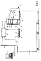
Other features and advantages of the sheet deposition device according to the invention will be explained hereinafter with reference to the accompanying drawings wherein: - Fig. 1 illustrates one embodiment of a printing apparatus using a sheet deposition device according to the invention,
- Fig. 2 shows the sheet deposition device of Fig. 1 with supports shown in their bottom positions,
- Fig. 3 is a perspective view of detection means mounted beneath each support of the sheet deposition device show in Figs. 1 and 2, and
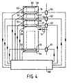
- Fig. 4 is a diagram showing a sheet deposition device with the supports in their starting position and an associated control system.
-
- The printing apparatus 1 shown in Fig. 1 comprises means known per se for printing an image on a receiving sheet. These images for printing may be present on original documents which are fed to a scanning station 2 situated at the top of the printing apparatus 1. Images for printing can also be fed in digital form from a workstation 3 connected via a network 4 to a control device 8 of the printing apparatus 1.
A printing cycle for copying a set of originals presented via the scanning station 2 is started by actuating astart button 6 on theoperator control panel 5 of the printing apparatus 1.
A printing cycle for printing a set of images presented via workstation 3 can be started by actuating a start button 7 provided on the workstation 3, via control device 8 (hereinafter referred to as automatic printing), or by actuating astart button 6 provided on theoperator control panel 5 of the printing apparatus 1 (hereinafter referred to as semi-automatic printing).
In the printing apparatus 1, thesheet transport path 10 forms the path for delivering to asheet finishing station 11 the sheets printed in the printing apparatus.
Thefinishing station 11 contains a sheet collecting tray 12 (not shown in detail) in which a number of printed sheets belonging to a set can be collected and stapled, whereafterdischarge roller pairs 13 feed the set of printed sheets to asheet deposition unit 15 forming part of asheet deposition station 11.
Thesheet deposition unit 15 comprises four superposed deposition tables 16, 17, 18 and 19, each of which can be set to a deposition position with respect to the horizontal discharge path formed by thedischarge roller pair 13, to receive sheets discharged by thedischarge roller pair 13. The vertical displacement of the deposition tables can be effected by means of the displacement mechanism described in European Patent Specification 0 532 069, the selected deposition table or the sheet at the top thereof always lying just beneath the discharge path formed by thedischarge roller pair 13.
Fig. 1 shows the bottom deposition table 16 in a bottom deposition position in which a maximum number of sheets is situated on said deposition table 16 and the deposition tables 17, 18 and 19 situated thereabove are in parking positions situated above the discharge path formed by thedischarge roller pair 13.
Since the deposition tables 17, 18 and 19 are adjustable as to height independently of deposition table 16, after sheets have been removed from deposition table 16 the top deposition table 19 can if necessary also be placed in a deposition position without the bottom deposition table 16 needing to be moved further down than the bottom deposition position shown in Fig. 1.
As a result, thefinishing station 11 with thesheet deposition unit 15 adjacent the same is very suitable for disposing at the top of a printing apparatus 1, the top of which with the scanning station 2 is situated at a normal working height for a standing operator of about 100 cm. In the printing apparatus 1 with thefinishing station 11 as shown in Fig. 1, the removal height for sheets delivered on deposition tables 16, 17, 18 and 19 is between 100 cm and 160 cm for a total sheet deposition capacity of about 3000 sheets. The sheet deposition level defined by thefixed discharge rollers 13 is approximately 133 cm, and this level corresponds to the deposition level at which the bottom deposition table 16 is in its bottom deposition position.
The combination of high deposition capacity and limited overall height is rendered possible by using the bottom deposition table 16 solely for the deposition of prints of a first type, the printing cycle of which is initiated with a setting button on the printing apparatus, so that the operator who makes this setting can also remove the deposited prints shortly thereafter, giving the deposition tables situated thereabove the opportunity to come into their deposition position and receive prints, the printing cycle of which is initiated from a workstation 3 at a distance from the printing apparatus.
According to the present invention, higher-level deposition tables can also be placed in a deposition position when prints are still situated on or beneath a lower-level deposition table providing there is still room to move the higher-level support down into its deposition position.
Therefor, according to the invention, each deposition table is provided with detection means which enable the higher-level deposition table to move down provided there is still free room for movement beneath said deposition table. The underside of each deposition table 17, 18 and 19 is for this purpose provided with the means indicated in Fig. 2.
To prevent the bottom deposition table 16 from jamming, during the downward movement, against an obstacle situated beneath the bottom deposition table, for example originals or copies lying on the top of the printing apparatus 1 next to the scanning station, the bottom deposition table 16 is also provided with the same detection means as the deposition table 17, 18 and 19. Therefor, each deposition table 16, 17, 18 and 19 is provided with twostraps
A U-shaped strap 27 extends at one of theadjacent straps strap 26 and is situated in the same horizontal plane as thestraps transport roller pair 13, thestraps 25 and 27 extend beneath the sides of the deposition plate and are rigidly connected thereto.
Pins straps 25 and 27 extending away from one another. Looking in the sheet discharge direction,pins straps 25 and 27. Aflat switch plate 32 extending parallel to the deposition plate is situated beneath thestraps brackets switch plate 32.
Upright parts of thebrackets slots pins pins straps
A U-shapedbent strip 39 is fixed on theswitch plate 32. The upright limbs of thestrip 39 are provided withindentations switch plate 32 is also provided with a strip which at the top has bent-overedges 43 which in the position of rest of theswitch plate 32 rest on aprojection 44 fixed on the strap 27. In the position of rest of theswitch plate 32, the top edges ofslots pins parts 43 rest onprojection 44. In this position of rest theswitch plate 32 is situated a short distance, e.g. a distance of 7 mm, beneath thestraps
When a deposition table moves down and theswitch plate 32 meets an obstacle therebeneath (e.g. a sheet stack on a deposition table therebeneath), then on the further downward movement of the deposition table theswitch plate 32 is pressed in the direction of thestraps switch plate 32 is made possible by theslots indentations switch plate 32 can not rotate about a line extending parallel to the sheet discharge direction. The switch plate can only tip about a line extending transversely of the sheet discharge direction. When theswitch plate 32 first comes into contact with an obstacle at the upstream side, then theswitch plate 32 moves upwards only at that side in the twoslots switch plate 32 first comes into contact with an obstacle on the downstream side then theswitch plate 32 moves up only on that side with rotation of the hinge arm 33, even if the obstacle is situated only beneath one comer part on that side.
An opto-electrical switch 45 is disposed on the upstream side of each deposition table between thestraps electrical switch 46 is disposed on the downstream side of each deposition table between the straps. Each of theswitches switch plate 32. During a movement of theswitch plate 32 in the direction of a downwardly moving deposition table, blade 47 and/or blade 47' will activate the associated switch orswitches
The switching time is so chosen thatswitch plate 32 can thereafter still move further before it encounters the straps. During this last movement, which can take place when the opto-electrical switch refuses to operate at the correct time, e.g., because the switch plate is pressed rapidly upwards manually, the blade actuates a microswitch (not shown) which for protection purposes breaks the drive to all the deposition tables. The protective microswitch does not normally respond. The above-described suspension of the switch plate ensures that activation of the switch plate can take place at each of the comer points, and yet only two switching elements are necessary instead of four. Theswitch plate 32 should be sufficiently torsion-resistant and is, therefore, constructed for example from 2 mm thick aluminium.
The use of the switch arm 33, situated around the straps between the deposition plate and the switch plate, ensures a flat construction which, for example, has a total overall height of only 20 mm with the required stroke length of 7 mm for the switch plate, of which, for example, 4 mm is for the opto-electrical switches and 3 mm for the protective microswitch.
At thedrive side 48, where they are connected to a motor which can adjust the associated deposition table as to height, thestraps elevation 49 by means of which they can come into contact with the strap of a deposition table thereabove. This elevation is of a size such that two tables between which there are no sheets cannot come so close together that the protective microswitch can respond. Only when there are sheets or some other obstacle between the deposition tables the microswitch can respond and the switching off of the motors which move the deposition tables can be rendered inoperative by the removal of the sheets which caused the microswitch to respond. - In Fig. 4, the four deposition tables 16, 17, 18 and 19 are shown in their starting positions. The bottom table 16 is in the lowest possible position which is at a distance beneath the
transport roller pair 13 such that it can support a predetermined maximum number of sheets, e.g. 2250 sheets. A fixedsensor 50 level with this position detects when thesupport 16 is in this starting position.
The other deposition tables 17, 18 and 19 are in their starting position above thetransport roller pair 13. Thesupport 17 just above it and supports 18 and 19 respectively at a distance thereabove such that each of these supports can support a predetermined maximum number of sheets, e.g. 500 sheets each.Fixed sensors supports
The above indicated starting positions correspond to positions in which the sheet deposition device accommodates a maximum number of sheets.
Reference 60 denotes a control device which sets the tables to their starting position for putting the sheet deposition device into operation.
First of all, by means ofmotor 61, table 16 is moved down to its very lowest position atsensor 50. Table 19 is then raised by means ofmotor 64 to its very highest position atsensor 53. Table 18 is then moved up by means ofmotor 63 until either the position atsensor 52 is reached, in the event that the table was previously in a lower position, orsensor 57 beneath table 19 is activated in the event that table 18 was previously in a higher position than the starting position. In the latter case, table 18 then moves down until it reaches the position atsensor 52. Table 17 is then raised by means ofmotor 63 until either the position atsensor 52 is reached, in the event that the table was previously in a lower position, orsensor 57 beneath table 19 is activated, in the event that table 17 was previously in a higher position than the starting position. In the latter case, table 17 then moves down until reaching the position atsensor 51.
When the control device 60 finds thatdetectors Detector 58 is provided if the sheet deposition device has acover plate 66 which prevents a free upward movement of the top table with (too) many sheets thereon.
Before the start of a print cycle the table selected for deposition is brought into the deposition position.
Starting from the starting position shown in Fig. 4, this implies the following: - If deposition on the bottom table 16 is selected,
motor 61 moves table 16 upwards until the top of said table is level withdetector 59 disposed at a fixed short distance beneath thesheet transport rollers 13. If there are sheets on table 16 the upward movement stops when the top sheet on the table 16 reachesdetector 59. - If deposition on table 17 is selected, this table moves down from the starting position
until the top of table 17 or the top sheet thereon comes in the range of
detector 59. When the downward movement stops beforedetector 59 can respond, that means that the deposition table 16 with any sheets thereon forms an obstacle and the control device 60 delivers a signal tomotor 61 to lower table 16 as well. If the latter is not possible because table 16 has reachedsensor 50, the control device 60 delivers a signal to the operator to remove sheets from table 16, for making space for further lowering of table 51 to its deposition position.
If a (further) downward movement of table 17 is no longer possible, while table 16 has not yet reached its extreme bottom position, then the control device 60 delivers a signal to the operator to remove sheets or some other obstacle beneath table 16. - If deposition on table 18 is selected, this table moves down until the top of the table
or, if sheets are present thereon, the top of the stack of sheets thereon, comes in the
range of
detector 59.
During this movement, table 18 may first encounter table 17 and activatedetector 56 in so doing. As a result,motor 62 is activated and moves table 17, together with table 18, downwards. Table 17 can then also meet table 16 or asheet stack 16 thereon, so thatmotor 61 is also activated in the manner explained hereinbefore in connection with selection of deposition on table 17. When table 16 has reached its starting position and if table 17 is then alreadypast detector 59 before table 18 reaches its deposition position, the control device 60 delivers a signal to the operator to remove sheets from the table 17. - If deposition on table 19 is selected, this table moves down until the top of the table
or, if sheets are present thereon, the top of a stack of sheets thereon, comes in the
range of
detector 59.
This movement can be interrupted whendetector 57 responds. Table 18 then also moves down.Detector 56 can then also respond so that table 17 also moves down. The same can then also occur at table 16. If in these conditions table 16 cannot come into its extreme bottom position, control device 60 delivers a signal for removal of sheets beneath table 16. If table 17 cannot then come beneathdetector 59, a signal is delivered for removal of sheets from table 17. Finally, if table 18 also cannot come beneathdetector 59, a signal is delivered for removal of sheets from table 18. - Before further deposition on one of the tables 17, 18 and 19, the control device 60 should in the first instance know where the associated table is situated, i.e. whether said table is situated beneath or above the deposition position. The reason for this is to enable the required direction of movement of the associated
motor
On a change of deposition from a higher-level table (e.g. table 18) to a lower-level table (e.g. table 17), the latter table should move upwards but in so doing meets the detector beneath the higher-level table,e.g. detector 56. When the latter respondsmotor 63 also moves table 18 upwards and possibly motor 64 then also moves table 19. If the top table in the latter case reaches its extreme top position atsensor 53 before table 17 has reached its deposition position, this means that there are too many sheets on table 17 and/or table 18. In the event of too many sheets on table 18, table 18 has not yet reached its starting position atsensor 52 and a signal is delivered to remove sheets from table 18. If in that case the table 18 has passedsensor 52, that is a signal that sheets must be removed from table 17.
During the deposition of sheets on a table, said table moves down stepwise to keep the top of the sheets deposited thereon in range of thedetector 59. In these conditions a detector mounted beneath the associated table can respond so that the table therebeneath is also moved down stepwise. Deposition stops when there are too many sheets on the associated table. In the case of deposition on table 16, this occurs when said table comes into its extreme bottom starting position atsensor 50. Deposition on table 17 stops when table 16 has moved down to its bottom-most starting position or when table 16 is already in that position on response of the detector 55. The stopping of deposition also applies accordingly in the case of deposition on table 18 or 19. - In some situations it may be convenient to be able to start deposition on a table which is still empty, e.g. in order to prevent copies for deposition from being added to sheets still on that table.
One solution to this problem comprises detectors on each table reacting to sheets thereon. - In the deposition of printed sheets of print jobs various types of print jobs are possible in which the deposition of printed sheets is distributed separately over different deposition tables.
- A distinction can be made between the following in the case of separate deposition:
- 1. Next job printing
Successive print jobs are as far as possible deposited on consecutive deposition tables in their natural sequence. A user at the printer thus clearly sees when the previous job has been completed and the next job starts. Removal of the previous job is also easier. - 2. Walk-up priority-printing
Print jobs initiated at the printer, i.e. not from a workstation at a distance from the printer, are deposited on a separate deposition table, e.g. on the bottom deposition table, so that the user present at the machine can see where his print job is situated. - 3. Interrupt printing
In these "interim" print jobs, the current print job is interrupted for an interim job. This interim job is deposited on a different deposition table than the interrupted job, preferably the next deposition table, in order to show clearly when the printing of the interim job starts and is finished and in order to facilitate removal of the interim prints. Another advantage is that the interrupted job is delivered with out separation. - 4. Continuous printing
The printer runs continuously in printing and deposits sheets provided there is still deposition space, i.e. for as long as deposition tables are emptied in good time. Deposition can start at the bottom deposition table and then continue on the deposition tables thereabove (bottom-up algorithm). Deposited prints are removed during printing and thus printing can carry on continuously. - 5. Capacity printing
In order to ensure that the deposition capacity is utilised to the maximum in the case of print jobs where the user is not present at the printer, deposition is first on the top deposition table and then continues with the deposition table therebeneath (top-down algorithm). - 6. Sorter printing
Print jobs are delivered sorted in respect of an adjustable feature, e.g. orders from users of group A on the bottom deposition table, of group B on the table thereabove, and so on (user groups), or orders with stapled sets on one deposition table and orders with non-stapled sets on another deliver table (stack quality printing). -
- It will be apparent that on a change of deposition from one deposition table to another deposition table, activation of the detection means suspended beneath the deposition tables plays an important role. They determine whether such change-over is possible and enable the sheet deposition device to allow such a change-over even when printed sheets are removed from deposition tables which are not in use. Without the detection means according to the invention, the sheet deposition device would assume that the number of sheets deposited on a deposition table will always remain thereon until all the sheets have been removed from said deposition table, and this is detectable in known manner by an empty-detector on a deposition table.
Claims (11)
- A sheet deposition device for the selective deposition of printed sheets on a number of superposed supports (16, 17, 18, 19) wherein each support is provided with its own drive means for moving said support up and down between a deposition position in which sheets can be delivered on that support and a parking position in which sheet deposition is not possible, characterised in that each support (16, 17, 18, 19) is provided with detection means (32, 45, 46) for detecting an obstacle in the space directly therebeneath, for example sheets on a support directly therebeneath, which detection means deliver a first detection signal when the distance between the support provided with said detection means and an obstacle directly therebeneath is greater than a predetermined amount and deliver a second detection signal when said distance is equal to said predetermined amount and in that the sheet deposition device comprises a control device which in response to reception of a first detection signal makes the drive means capable of activation for moving towards one another the supports between which are situated the detection means delivering the first detection signal and which deactivate the said drive means in response to the reception of a second detection signal.
- A sheet deposition device according to claim 1, characterised in that the detection means comprises a flat plate (32) suspended beneath a support and movable between a first position in which the plate (32) is situated at some distance from and parallel to said support and a second position in which the plate is situated at an even shorter distance from said support and in that the detection means further comprise switching means (45, 47; 46, 48) between the plate (32) and the support with actuating means (47; 48) which are rigidly connected to the movable plate and in the first position of the plate (32) actuate the switching means (45; 46) to deliver the first detection signal and in the second position of the plate (32) actuate the switching means (45; 46) for delivery of the second detection signal.
- A sheet deposition device according to claim 2, characterised in that the plate (32) is provided with fixing means (28, 29, 35-38; 30, 31, 33, 39-41) near opposite edges, which fixing means connect the plate to the support for movement in the vertical direction and in that the switching means (45, 47) are provided at each of said fixing means.
- A sheet deposition device according to claim 3, characterised in that one of said fixing means comprises a U-shaped strap (33), of which the intermediate piece connecting its limbs is connected (40, 41) for rotation about its longitudinal axis to one of the plates or supports for connection and the ends of the limbs are rotatably connected (30, 31) to the other plate or support for connection.
- A sheet deposition device according to any one of claims 2 to 4, characterised in that the dimensions of the flat plate (32) correspond to the dimensions of the largest sheet for deposition.
- A device according to any one of the preceding claims, characterised in that the control device of the sheet deposition device comprises first control means which in response to the reception of a first detection signal delivered by the detection means at a support in a deposition position make the drive means capable of activation for moving said support downwards on deposition of following sheets on said support.
- A sheet deposition device according to any one of the preceding claims, characterised in that the control device comprises second control means which in response to the reception of a first detection signal delivered by the detection means at a support in a parking position and at a lower level than a support in a deposition position make the drive means capable of activation of said support in the parking position, the support in the deposition position and the supports therebetween for moving said supports downwards on deposition of following sheets on the support in the deposition position.
- A sheet deposition device according to any one of the preceding claims, characterised in that the control device comprises third control means which on downward movement of a support from a parking position into its deposition position and in response to the reception of a first detection signal delivered by the detection means at a support at a lower level than the support for displacement to its deposition position make the drive means of said lower-level support or supports capable of activation for joint downward movement of the support for displacement into its deposition position.
- A sheet deposition device according to any one of the preceding claims, characterised in that the control device comprises fourth control means which on upward displacement of a support from a parking position into its deposition position and in response to the reception of a first detection signal delivered by the detection means at a support situated above a support at a higher level than the support for displacement into its deposition position make the drive means of the intermediate support or supports capable of activation for joint upward movement of the intermediate support or supports.
- A sheet deposition device according to any one of the preceding claims, characterised in that further detection means are also fixed above the top support for the detection of sheets on said top support and deliver a first detection signal when the distance between the fixed detection means and the top sheet on the top support is greater than a predetermined amount and deliver a second detection signal when said distance is equal to the predetermined amount.
- A sheet deposition device according to claim 10, characterised in that the control device comprises fifth control means which in response to the reception of a first detection signal delivered by the fixed detection means make the drive means of the top support capable of activation for raising the top support and which in response to the reception of a second detection signal delivered by the fixed detection means deactivate the drive means of the top support to stop the movement of the top support.
Applications Claiming Priority (2)
| Application Number | Priority Date | Filing Date | Title |
|---|---|---|---|
| NL1012923A NL1012923C2 (en) | 1999-08-27 | 1999-08-27 | Sheet depositing device for selectively depositing sheets on superimposed carriers. |
| NL1012923 | 1999-08-27 |
Publications (2)
| Publication Number | Publication Date |
|---|---|
| EP1086917A1 true EP1086917A1 (en) | 2001-03-28 |
| EP1086917B1 EP1086917B1 (en) | 2004-02-04 |
Family
ID=19769795
Family Applications (1)
| Application Number | Title | Priority Date | Filing Date |
|---|---|---|---|
| EP00202859A Expired - Lifetime EP1086917B1 (en) | 1999-08-27 | 2000-08-16 | A sheet deposition device for selective deposition of sheets on superposed supports |
Country Status (5)
| Country | Link |
|---|---|
| US (1) | US6361039B1 (en) |
| EP (1) | EP1086917B1 (en) |
| JP (1) | JP2001097628A (en) |
| DE (1) | DE60008053T2 (en) |
| NL (1) | NL1012923C2 (en) |
Cited By (2)
| Publication number | Priority date | Publication date | Assignee | Title |
|---|---|---|---|---|
| US6361039B1 (en) * | 1999-08-27 | 2002-03-26 | Océ-Technologies B.V. | Sheet deposition device for selective deposition of sheets on superimposed supports |
| EP2033919A3 (en) * | 2007-07-18 | 2011-12-07 | Heidelberger Druckmaschinen Aktiengesellschaft | Printing press with electric anti-crush protection |
Families Citing this family (3)
| Publication number | Priority date | Publication date | Assignee | Title |
|---|---|---|---|---|
| DE102004002307A1 (en) * | 2003-02-03 | 2004-08-12 | Heidelberger Druckmaschinen Ag | Procedure for synchronisation of movement sequences of main and additional piles of printed material in sheet feeder entails additional pile control unit receiving from main pile control unit start signal to move additional pile |
| JP4362607B2 (en) * | 2003-03-12 | 2009-11-11 | 旭精工株式会社 | Bill movement device in bill storage device |
| JP2006315812A (en) * | 2005-05-13 | 2006-11-24 | Canon Inc | Sheet processing apparatus and image forming apparatus |
Citations (1)
| Publication number | Priority date | Publication date | Assignee | Title |
|---|---|---|---|---|
| EP0532069A1 (en) * | 1991-08-01 | 1993-03-17 | Océ-Nederland B.V. | A device for depositing sheets on supports situated one above the other |
Family Cites Families (11)
| Publication number | Priority date | Publication date | Assignee | Title |
|---|---|---|---|---|
| DD115336A1 (en) * | 1974-03-28 | 1975-09-20 | ||
| JPS5823309B2 (en) * | 1980-10-31 | 1983-05-14 | 宇野 忠男 | Automatic paper replenishment device for top feeder type paper feeder |
| JPH0733283A (en) * | 1993-07-16 | 1995-02-03 | Ricoh Co Ltd | Mass paper feeder |
| JP3850457B2 (en) * | 1994-07-14 | 2006-11-29 | 株式会社リコー | Image forming system apparatus |
| JPH0873107A (en) * | 1994-09-05 | 1996-03-19 | Canon Inc | Sorting device and image forming device |
| JP3620009B2 (en) * | 1997-06-23 | 2005-02-16 | シャープ株式会社 | Sheet accumulation processing device |
| NL1006471C2 (en) * | 1997-07-04 | 1999-01-05 | Oce Tech Bv | Printing device with selective deposition of printed sheets on height-adjustable carriers. |
| DE19735895C1 (en) * | 1997-08-19 | 1998-09-10 | Roland Man Druckmasch | Lifting drive for automatic stack changer for offset sheet printing machine |
| US6231045B1 (en) * | 1998-06-12 | 2001-05-15 | Ricoh Company, Ltd. | Finisher for an image forming apparatus |
| US6227539B1 (en) * | 1998-10-21 | 2001-05-08 | Xerox Corporation | Printer mailboxing system with automatic variable capacity bins |
| NL1012923C2 (en) * | 1999-08-27 | 2001-02-28 | Ocu Technologies B V | Sheet depositing device for selectively depositing sheets on superimposed carriers. |
-
1999
- 1999-08-27 NL NL1012923A patent/NL1012923C2/en not_active IP Right Cessation
-
2000
- 2000-08-16 DE DE60008053T patent/DE60008053T2/en not_active Expired - Lifetime
- 2000-08-16 EP EP00202859A patent/EP1086917B1/en not_active Expired - Lifetime
- 2000-08-25 US US09/645,597 patent/US6361039B1/en not_active Expired - Lifetime
- 2000-08-25 JP JP2000256138A patent/JP2001097628A/en active Pending
Patent Citations (1)
| Publication number | Priority date | Publication date | Assignee | Title |
|---|---|---|---|---|
| EP0532069A1 (en) * | 1991-08-01 | 1993-03-17 | Océ-Nederland B.V. | A device for depositing sheets on supports situated one above the other |
Cited By (3)
| Publication number | Priority date | Publication date | Assignee | Title |
|---|---|---|---|---|
| US6361039B1 (en) * | 1999-08-27 | 2002-03-26 | Océ-Technologies B.V. | Sheet deposition device for selective deposition of sheets on superimposed supports |
| EP2033919A3 (en) * | 2007-07-18 | 2011-12-07 | Heidelberger Druckmaschinen Aktiengesellschaft | Printing press with electric anti-crush protection |
| US8151706B2 (en) | 2007-07-18 | 2012-04-10 | Heidelberger Druckmaschinen Ag | Apparatus with electrical crush protector and printing press having the apparatus |
Also Published As
| Publication number | Publication date |
|---|---|
| EP1086917B1 (en) | 2004-02-04 |
| US6361039B1 (en) | 2002-03-26 |
| NL1012923C2 (en) | 2001-02-28 |
| DE60008053T2 (en) | 2004-12-02 |
| DE60008053D1 (en) | 2004-03-11 |
| JP2001097628A (en) | 2001-04-10 |
Similar Documents
| Publication | Publication Date | Title |
|---|---|---|
| US5823529A (en) | Single stack height sensor for plural sheet stacking bins system | |
| US5609333A (en) | Sheet stack height control system | |
| US5599009A (en) | Stacking height estimation correction system | |
| EP0888994B1 (en) | A printing apparatus for selective deposition of printed sheets on supports which are adjustable as to height | |
| US5603492A (en) | Sheet stacking bin fullness control system | |
| US8086165B2 (en) | Bookbinding system and bookbinding apparatus | |
| US20040051238A1 (en) | Finisher for an image forming apparatus | |
| US6091927A (en) | Apparatus and method for feeding documents to an image forming apparatus, scanner, or the like | |
| EP1086917B1 (en) | A sheet deposition device for selective deposition of sheets on superposed supports | |
| EP1078873B1 (en) | Method of and apparatus for selectively depositing printed sheets on superposed supports | |
| US5192261A (en) | Apparatus for post-processing sheets | |
| CA2186973C (en) | Sheet stacking bin fullness control system | |
| EP0532069B1 (en) | A device for depositing sheets on supports situated one above the other | |
| JPH0776069B2 (en) | Copying device | |
| JP3566108B2 (en) | Document feeder | |
| JP2010276788A (en) | Image forming apparatus | |
| JPH069144A (en) | Sheet post-processing apparatus and image forming apparatus including this apparatus | |
| JP3337500B2 (en) | Seat storage device | |
| JP3721171B2 (en) | Paper sheet feeder | |
| JP2000159418A (en) | Image forming device | |
| JP2000313560A (en) | Paper loading device | |
| JPH06219597A (en) | Image forming system | |
| JP2003226440A (en) | Paper feeder | |
| JPH10157860A (en) | Automatic document feeder | |
| JP2005041583A (en) | Image forming device and post processing device |
Legal Events
| Date | Code | Title | Description |
|---|---|---|---|
| PUAI | Public reference made under article 153(3) epc to a published international application that has entered the european phase |
Free format text: ORIGINAL CODE: 0009012 |
|
| AK | Designated contracting states |
Kind code of ref document: A1 Designated state(s): DE FR GB NL |
|
| AX | Request for extension of the european patent |
Free format text: AL;LT;LV;MK;RO;SI |
|
| 17P | Request for examination filed |
Effective date: 20010928 |
|
| AKX | Designation fees paid |
Free format text: DE FR GB NL |
|
| 17Q | First examination report despatched |
Effective date: 20021016 |
|
| GRAP | Despatch of communication of intention to grant a patent |
Free format text: ORIGINAL CODE: EPIDOSNIGR1 |
|
| GRAS | Grant fee paid |
Free format text: ORIGINAL CODE: EPIDOSNIGR3 |
|
| GRAA | (expected) grant |
Free format text: ORIGINAL CODE: 0009210 |
|
| AK | Designated contracting states |
Kind code of ref document: B1 Designated state(s): DE FR GB NL |
|
| REG | Reference to a national code |
Ref country code: GB Ref legal event code: FG4D |
|
| REF | Corresponds to: |
Ref document number: 60008053 Country of ref document: DE Date of ref document: 20040311 Kind code of ref document: P |
|
| ET | Fr: translation filed | ||
| PLBE | No opposition filed within time limit |
Free format text: ORIGINAL CODE: 0009261 |
|
| STAA | Information on the status of an ep patent application or granted ep patent |
Free format text: STATUS: NO OPPOSITION FILED WITHIN TIME LIMIT |
|
| 26N | No opposition filed |
Effective date: 20041105 |
|
| REG | Reference to a national code |
Ref country code: FR Ref legal event code: PLFP Year of fee payment: 17 |
|
| PGFP | Annual fee paid to national office [announced via postgrant information from national office to epo] |
Ref country code: NL Payment date: 20160817 Year of fee payment: 17 |
|
| PGFP | Annual fee paid to national office [announced via postgrant information from national office to epo] |
Ref country code: GB Payment date: 20160819 Year of fee payment: 17 Ref country code: DE Payment date: 20160822 Year of fee payment: 17 |
|
| PGFP | Annual fee paid to national office [announced via postgrant information from national office to epo] |
Ref country code: FR Payment date: 20160822 Year of fee payment: 17 |
|
| REG | Reference to a national code |
Ref country code: DE Ref legal event code: R119 Ref document number: 60008053 Country of ref document: DE |
|
| REG | Reference to a national code |
Ref country code: NL Ref legal event code: MM Effective date: 20170901 |
|
| GBPC | Gb: european patent ceased through non-payment of renewal fee |
Effective date: 20170816 |
|
| REG | Reference to a national code |
Ref country code: FR Ref legal event code: ST Effective date: 20180430 |
|
| PG25 | Lapsed in a contracting state [announced via postgrant information from national office to epo] |
Ref country code: NL Free format text: LAPSE BECAUSE OF NON-PAYMENT OF DUE FEES Effective date: 20170901 |
|
| PG25 | Lapsed in a contracting state [announced via postgrant information from national office to epo] |
Ref country code: GB Free format text: LAPSE BECAUSE OF NON-PAYMENT OF DUE FEES Effective date: 20170816 Ref country code: DE Free format text: LAPSE BECAUSE OF NON-PAYMENT OF DUE FEES Effective date: 20180301 |
|
| PG25 | Lapsed in a contracting state [announced via postgrant information from national office to epo] |
Ref country code: FR Free format text: LAPSE BECAUSE OF NON-PAYMENT OF DUE FEES Effective date: 20170831 |