EP1086838A1 - Structure and method for mounting damper - Google Patents
Structure and method for mounting damper Download PDFInfo
- Publication number
- EP1086838A1 EP1086838A1 EP00915453A EP00915453A EP1086838A1 EP 1086838 A1 EP1086838 A1 EP 1086838A1 EP 00915453 A EP00915453 A EP 00915453A EP 00915453 A EP00915453 A EP 00915453A EP 1086838 A1 EP1086838 A1 EP 1086838A1
- Authority
- EP
- European Patent Office
- Prior art keywords
- damper
- shaft
- concave groove
- lever
- casing
- Prior art date
- Legal status (The legal status is an assumption and is not a legal conclusion. Google has not performed a legal analysis and makes no representation as to the accuracy of the status listed.)
- Granted
Links
Images


Classifications
-
- B—PERFORMING OPERATIONS; TRANSPORTING
- B60—VEHICLES IN GENERAL
- B60H—ARRANGEMENTS OF HEATING, COOLING, VENTILATING OR OTHER AIR-TREATING DEVICES SPECIALLY ADAPTED FOR PASSENGER OR GOODS SPACES OF VEHICLES
- B60H1/00—Heating, cooling or ventilating [HVAC] devices
- B60H1/00642—Control systems or circuits; Control members or indication devices for heating, cooling or ventilating devices
- B60H1/00664—Construction or arrangement of damper doors
- B60H1/00671—Damper doors moved by rotation; Grilles
- B60H1/00678—Damper doors moved by rotation; Grilles the axis of rotation being in the door plane, e.g. butterfly doors
-
- B—PERFORMING OPERATIONS; TRANSPORTING
- B60—VEHICLES IN GENERAL
- B60H—ARRANGEMENTS OF HEATING, COOLING, VENTILATING OR OTHER AIR-TREATING DEVICES SPECIALLY ADAPTED FOR PASSENGER OR GOODS SPACES OF VEHICLES
- B60H1/00—Heating, cooling or ventilating [HVAC] devices
- B60H1/00642—Control systems or circuits; Control members or indication devices for heating, cooling or ventilating devices
- B60H1/00814—Control systems or circuits characterised by their output, for controlling particular components of the heating, cooling or ventilating installation
- B60H1/00821—Control systems or circuits characterised by their output, for controlling particular components of the heating, cooling or ventilating installation the components being ventilating, air admitting or air distributing devices
- B60H1/00835—Damper doors, e.g. position control
- B60H1/00857—Damper doors, e.g. position control characterised by the means connecting the initiating means, e.g. control lever, to the damper door
-
- F—MECHANICAL ENGINEERING; LIGHTING; HEATING; WEAPONS; BLASTING
- F24—HEATING; RANGES; VENTILATING
- F24F—AIR-CONDITIONING; AIR-HUMIDIFICATION; VENTILATION; USE OF AIR CURRENTS FOR SCREENING
- F24F13/00—Details common to, or for air-conditioning, air-humidification, ventilation or use of air currents for screening
- F24F13/08—Air-flow control members, e.g. louvres, grilles, flaps or guide plates
- F24F13/10—Air-flow control members, e.g. louvres, grilles, flaps or guide plates movable, e.g. dampers
- F24F13/14—Air-flow control members, e.g. louvres, grilles, flaps or guide plates movable, e.g. dampers built up of tilting members, e.g. louvre
- F24F13/1486—Air-flow control members, e.g. louvres, grilles, flaps or guide plates movable, e.g. dampers built up of tilting members, e.g. louvre characterised by bearings, pivots or hinges
-
- B—PERFORMING OPERATIONS; TRANSPORTING
- B60—VEHICLES IN GENERAL
- B60H—ARRANGEMENTS OF HEATING, COOLING, VENTILATING OR OTHER AIR-TREATING DEVICES SPECIALLY ADAPTED FOR PASSENGER OR GOODS SPACES OF VEHICLES
- B60H1/00—Heating, cooling or ventilating [HVAC] devices
- B60H1/00642—Control systems or circuits; Control members or indication devices for heating, cooling or ventilating devices
- B60H1/00664—Construction or arrangement of damper doors
- B60H2001/00707—Details of pivots of damper doors
-
- Y—GENERAL TAGGING OF NEW TECHNOLOGICAL DEVELOPMENTS; GENERAL TAGGING OF CROSS-SECTIONAL TECHNOLOGIES SPANNING OVER SEVERAL SECTIONS OF THE IPC; TECHNICAL SUBJECTS COVERED BY FORMER USPC CROSS-REFERENCE ART COLLECTIONS [XRACs] AND DIGESTS
- Y10—TECHNICAL SUBJECTS COVERED BY FORMER USPC
- Y10T—TECHNICAL SUBJECTS COVERED BY FORMER US CLASSIFICATION
- Y10T137/00—Fluid handling
- Y10T137/0318—Processes
- Y10T137/0402—Cleaning, repairing, or assembling
- Y10T137/0491—Valve or valve element assembling, disassembling, or replacing
- Y10T137/0525—Butterfly valve
-
- Y—GENERAL TAGGING OF NEW TECHNOLOGICAL DEVELOPMENTS; GENERAL TAGGING OF CROSS-SECTIONAL TECHNOLOGIES SPANNING OVER SEVERAL SECTIONS OF THE IPC; TECHNICAL SUBJECTS COVERED BY FORMER USPC CROSS-REFERENCE ART COLLECTIONS [XRACs] AND DIGESTS
- Y10—TECHNICAL SUBJECTS COVERED BY FORMER USPC
- Y10T—TECHNICAL SUBJECTS COVERED BY FORMER US CLASSIFICATION
- Y10T137/00—Fluid handling
- Y10T137/598—With repair, tapping, assembly, or disassembly means
- Y10T137/6031—Assembling or disassembling rotary valve
- Y10T137/6048—Butterfly valve
Definitions
- the present invention relates to a damper attaching structure and damper attaching method for a damper attached inside various types of casings in an air conditioning for a vehicle system or the like.
- Figs. 5 and 6 show an overview of an air conditioning unit employed in a conventional air-conditioning system for a vehicle.
- Outlet ports 2a, 2b, and 2c open in a casing 1.
- Dampers 3a, 3b, and 3c are attached to outlet ports 2a, 2b, and 2c respectively.
- the casing 1 is designed to be formed by combining two separate left and right parts (1L, 1R).
- an easy assembly is facilitated by passing rotational shafts provided to either end of the dampers into bearings in the casing 1, and inserting these rotational shafts into these bearings.
- FIG. 7 employs a design in which the casing 1 is divided into upper and lower parts (1a, 1b) at a position at which a bearing 5 for supporting a rotational shaft 4 of a damper 2 can be divided into upper and lower portions.
- This design also facilitates easy assembly by inserting the rotational shaft 4 from a vertical direction into the bearing 5.
- the above-described damper 2 can be opened and closed by a lever 6 attached to the outside of the casing 1. As shown in Fig. 8, this lever 6 is attached by fixing to the end of the rotational shaft 4 which projects to the outside of the casing 1.
- a shaft 6a is provided projecting outward from the lever 6, and can be attached by engaging in a shaft hole 4a which is provided in the rotational shaft 4.
- the damper 2 can be shortened by an amount corresponding to the rotational shafts 4 at either end thereof. Accordingly, the damper 2 can be incorporated inside the casing 1 by employing an appropriate opening such as an outlet port or a port communicating to another casing.
- the damper can be assembled from an opening such as an outlet port without considering the division of the casing.
- the present invention was conceived in consideration of the above-described problems and has as its objective the provision of a damper attaching structure and damper attaching method in which a damper provided with a narrow rotational shaft can be assembled inside a casing by employing openings formed in various types of casings such as casing or duct.
- the present invention employs the following means.
- the present invention provides a damper attaching structure in which both ends of a damper which is disposed between opposing wall members of a casing or the like are supported by the wall members in a manner so as to enable free rotation and the rotation operation of the damper is performed via a lever attached by a damper shaft on the outside of the wall member,
- the damper attaching structure comprising: a concave groove formed in the inner surface of the wall member and continuous with a casing opening; a positioning member provided at the base of the damper shaft on the damper side thereof; a shaft hole opening at the concave groove, which is larger than the cross section of the damper shaft; a shaft fixing member provided on the lever and rotatably inserted into the shaft hole; and an engaging hole into which the damper shaft member is inserted and which engages the damper shaft member to enable torque transmission; wherein the concave groove is larger in shape than the positioning member, the positioning member is inserted into the concave groove at the attachment position of the damper, and the positioning member adjusts
- the angle formed between the positioning member and a center line in the longitudinal direction of the concave groove at a position of the rotational center when the damper is operating may be set to approximately 90°.
- the damper shaft and the engaging hole have the same polygonal shape in cross section.
- the lever may be joined to the damper shaft which has been inserted into the shaft hole by pushing the lever in the direction of the shaft from the outside of the wall member.
- damper attaching structure even if the damper shaft is thin and it is not possible to employ a divided structure suitable to the casing or the like, it is still possible to incorporate the damper from the casing opening and attach the lever.
- the present invention provides a damper attaching method, wherein both ends of a damper which is disposed between opposing wall members of a casing or the like are supported by the wall members in a manner so as to enable free rotation and the rotation operation of the damper is performed via a lever attached by a damper shaft on the outside of the wall member
- the damper attaching structure comprising: a first step in which the end of the damper shaft and a positioning member, which is provided at the base of the damper shaft on the damper side thereof, are inclined downward and inserted into a concave groove that is formed in the inner surface of the wall member and is continuous with a casing opening, and the damper shaft is inserted into a shaft hole which opens at the concave groove and which is larger than the cross section of the damper shaft; a second step in which, after the positioning member has been inserted into the concave groove and the damper has been moved to the lever attachment side, the damper shaft which is circular in cross section is inserted into the shaft hole which is circular in
- the rotation of the damper from the attachment position to the rotation position in the third step may be approximately 90°.
- the damper attaching structure comprises a casing 10, wall members 11 and 12 of the casing 10 disposed opposite one another, an opening 13 provided at the upper portion of casing 10, a damper 20, and a lever 30 for rotating (opening/closing) the damper 20.
- Fig. 1A shows a completed assembly, in which both ends of the damper 20, which is provided in between the opposing wall members of the casing 10, are supported by the wall members 11 and 12 so as to enable free rotating of the damper.
- Fig. 1A shows the state in which damper 20 is at the center position of rotation.
- a shaft hole 14 is provided in the wall member 11 so as to pass through the wall member 11 and reach to the outside of the wall member 11.
- a shaft fixing member 31 of the lever 30 explained below is rotatably inserted into the shaft hole 14.
- This shaft hole 14 has a larger cross section than that of a damper thin shaft member 22 of the damper 20 explained below.
- a support hole 15 is provided to the other wall member 12 and functions as a bearing for a damper shaft member 21 which projects outward from the damper 20. Note that this support hole 15 may be provided with an intermediate thickness as shown in the figure, or may be a hole passing through the wall member 12, according to various conditions such as the thickness of the wall member 12.
- a concave groove 16 is provided to the inner surface 11a of the wall member 11 to which the lever 30 is attached.
- This concave groove 16 is rectangular in shape and is open at the upper end toward an opening 13.
- the width W of the concave groove 16 is smaller than the length L in the vertical direction.
- a center line extending along the longitudinal direction of the concave groove 16 is in the vertical direction, and the concave groove 16 has a positional relationship with the damper 20 such that it deviates by approximately 90° from the longitudinal plane of the damper 20 when the damper 20 is horizontal and at its center position of rotating.
- the damper 20 is a plate-shaped member provided with the damper shaft member 21 and the damper thin shall member 22 which are provided projecting out from either end of the damper 20.
- a rectangular positioning plate 23 which functions as a positioning member is provided to the base of damper thin shaft member 22 on the damper side thereof, on the wall member 11 side to which the lever 30 is attached. This positioning plate 23 is designed to enter into the above-described concave groove 16.
- the length and width of positioning plate 23 are less than that of concave groove 16. It is preferable that the thickness of positioning plate 23 is less than the depth of concave groove 16.
- the damper thin shaft member 22 is square in cross section. Since the objective is that the damper thin shaft member 22 and the lever 30 explained below are connected in a manner that enables torque transmission, not only a square but also polygonal shapes, such as a triangle or hexagon, which can be easily fabricated may also be employed. In other words, any of these shapes is acceptable for the cross sectional shape of the damper thin shaft member 22, provided that it will engage in the shaft hole on the lever 30 side and enable torque transmission.
- the shaft fixing member 31 projects out from a lever main body 32, so that the lever 30 is L-shaped.
- the lever 30 is typically connected to a driving member via a link structure or the like not pictured in the figures.
- this shaft fixing member 31 has a hollow cylindrical shape.
- An engaging hole 33 is formed at the center of shaft fixing member 31 into which the damper thin shaft member 22 is inserted, joining in a manner so as to enable torque transmission.
- the outer peripheral surface of shaft fixing member 31 is circular in cross section and is inserted into the shaft hole 14 of the wall member 11 in a manner so as to enable rotating.
- the engaging hole 33 in this embodiment has a square shape in cross section, equivalent to that of damper thin shaft member 22 so that the damper thin shaft member 22 can engage in the engaging hole without backlash.
- the circular cross sectional shape of the shaft fixing member 31 has the same diameter as the shaft hole 14, so that shaft fixing member 31 inserts into shaft hole 14 to enable smooth rotation without rattling.
- the lever 30 is designed to connect to the damper thin shaft member 22 that has been inserted into the shaft hole 14 by pushing the lever 30 from the outside of wall member 11 in the shaft direction. As a result, this offers excellent operability, and enables the lever 30 to be fixed in place with surety.
- Fig. 2 shows the state prior to assembly of the damper 20.
- the damper 20 is inclined toward the concave groove 16 which is formed to the inner surface 11a of wall member 11 and is continuous from casing opening 13.
- the end of damper thin shaft member 22 and positioning plate 23, which is provided to the base of damper thin shaft member 22, are inclined downward, introduced into concave groove 16 and lowered by sliding along the concave groove 16.
- damper thin shaft member 22 is inserted into shaft hole 14 which opens in concave groove 16 (see Fig. 3).
- the concave groove 16 functions as a recess for damper shaft member 21 and damper thin shaft member 22.
- the shaft hole 14 is larger in cross section than that of damper thin shaft member 22, so that the inclined damper thin shaft member 22 is easy to insert.
- the presence of concave groove 16 is one reason why the damper thin shaft member 22 readily inserts into the shaft hole 14.
- the second step after the damper thin shaft member 22 is introduced into the shaft hole 14 is as follows.
- the positioning plate 23 is inserted into the concave groove 16, and the shaft member of damper 20 is no longer inclined but is made level.
- the positioning plate 23 is tightly contacted to the opposing surface on concave groove 16 by moving the damper 20 toward the wall member 11 side where the lever is attached.
- damper shaft member 21 and damper thin shaft member 22, and the depth of concave groove 16, are set so that the end surface of damper shaft member 21 can be introduced into the wall member 12 from its inner surface 12a.
- the damper shaft member 21 which is circular in cross section, can be inserted into the support hole 15, which has the same circular cross section and is provided in wall member 12.
- the damper thin shaft member 22 is loose within the shaft hole 14 which has a larger cross sectional shape than that of damper thin shaft member 22.
- a part of or the whole of the positioning plate 23 is within the concave groove 16 and extends in the center direction of the casing at this point in time.
- the damper 20 is in the attachment position in this state.
- the damper 20 is rotated approximately 90° from the attachment position to the rotation position.
- the damper 20 is moved 90° from the attachment position in which the damper is vertical (see Fig. 4), to the rotation position in which it the damper is horizontal as shown in Fig. 1A.
- the damper 20 at the rotation position can oscillate employing the horizontal as the center of rotation.
- the length of positioning plate 23 is longer than the width W of concave groove 16 at this rotational center, so that positioning plate 23 intersects with the concave groove 16 (see Fig. 1B), and cannot be introduced into the concave groove 16.
- positioning plate 23 and the inner surface 11a of wall member 11 come into contact, so that positioning along the shaft direction of damper 20 occurs.
- rectangular positioning plate 23 is not provided with a certain length dimension, then the limits within which the damper 20 can oscillate are reduced. Since the angle formed between the center line of positioning plate 23 and the center line along the longitudinal direction of concave groove 16 is set to be around 90°, it is possible to increase the limits within which damper 20 can oscillate.
- the shaft fixing member 31 which has the same circular shape as the circular shaft hole 14 is inserted, and the damper thin shaft member 22 which is square in cross section engages with the engaging hole 33 in the shaft fixing member 31, the engaging hole 33 having the same cross sectional shape as the damper thin shaft member 22.
- the damper thin shaft member 22 and the lever 30 are connected in a manner that enables torque transmission, so that the damper shaft member 21 and the shaft fixing member 31 can be smoothly rotated employing the support hole 15 and the shaft hole 14 as their respective bearings.
- the operation to attach the lever 30 can also be performed prior to moving the damper 20 to the rotation position. Namely, in this case, the damper 20 may be moved to the rotation position after attachment of the lever 30.
- the damper attaching structure and the damper attaching method of the present invention enable the damper 20 which is longer than the wall members 11 and 12 to be assembled inside the casing by inserting through the opening 13. As a result, it is not absolutely necessary to separate the casing at the attachment position for the damper 20. Further, when attaching a plurality of dampers 20, it may be the case that the directions for inserting and attaching the dampers are not the same. However, even in this type of situation, the present invention enables the dampers to be assembled without considering dividing the casing.
- an opening such as a casing connection opening or a suitably shaped outlet port
- the present invention can be easily executed by employing these openings effectively.
- the length of positioning plate 23 is disposed so as to be level with the damper 20. However, this may be suitably altered after taking into consideration the position of opening 13 and the oscillation limits for damper 20. Namely, the length of positioning plate 23 may be set so that the angle between the long side of positioning plate 23 and damper 20 is 90° or 60°, for example.
- damper attaching structure and damper attaching method the present invention provide the following effects.
Abstract

Description
- The present invention relates to a damper attaching structure and damper attaching method for a damper attached inside various types of casings in an air conditioning for a vehicle system or the like.
- This application is based on Japanese Patent Application No. Hei 11-103344, the contents of which are incorporated herein by reference.
- In an air conditioning system for an automobile, it has been the conventional practice to attach dampers for performing temperature adjustments or selective switching of outlet ports inside a casing.
- Figs. 5 and 6 show an overview of an air conditioning unit employed in a conventional air-conditioning system for a vehicle.
Outlet ports casing 1.Dampers outlet ports damper casing 1 in this case, thecasing 1 is designed to be formed by combining two separate left and right parts (1L, 1R). As a result of this design, an easy assembly is facilitated by passing rotational shafts provided to either end of the dampers into bearings in thecasing 1, and inserting these rotational shafts into these bearings. - In addition, another conventional example shown in Fig. 7 employs a design in which the
casing 1 is divided into upper and lower parts (1a, 1b) at a position at which abearing 5 for supporting arotational shaft 4 of adamper 2 can be divided into upper and lower portions. This design also facilitates easy assembly by inserting therotational shaft 4 from a vertical direction into thebearing 5. - The above-described
damper 2 can be opened and closed by alever 6 attached to the outside of thecasing 1. As shown in Fig. 8, thislever 6 is attached by fixing to the end of therotational shaft 4 which projects to the outside of thecasing 1. - Alternatively, as shown in Fig. 9, when the
rotational shaft 4 is provided with a certain degree of thickness, then a shaft 6a is provided projecting outward from thelever 6, and can be attached by engaging in a shaft hole 4a which is provided in therotational shaft 4. In this type of lever attachment structure, it is not necessary to provide therotational shaft 4 projecting out from thedamper 2. As a result, thedamper 2 can be shortened by an amount corresponding to therotational shafts 4 at either end thereof. Accordingly, thedamper 2 can be incorporated inside thecasing 1 by employing an appropriate opening such as an outlet port or a port communicating to another casing. - However, in the above-described conventional design, it is typically necessary to decide where to divide the casing after taking into consideration the incorporation of the damper within the casing. Thus, there are limitations to the inclination and direction of the plurality of outlet ports installed, so that there is less freedom of design.
- By employing the lever attachment structure shown in Fig. 9 when the rotational shaft of the damper has a certain thickness, the damper can be assembled from an opening such as an outlet port without considering the division of the casing.
- However, in the case where the rotational shaft is not sufficiently thick and it is not possible to employ a design in which the casing is divided at the bearing, or a design in which the casing is divided into left and right portions and the rotational shaft is inserted therebetween, then it is not possible to incorporate the damper inside the casing. Specifically, when there are a large number of dampers to be incorporated, then it is extremely difficult to employ a design for dividing the casing that is suitable for all the dampers.
- The present invention was conceived in consideration of the above-described problems and has as its objective the provision of a damper attaching structure and damper attaching method in which a damper provided with a narrow rotational shaft can be assembled inside a casing by employing openings formed in various types of casings such as casing or duct.
- In order to resolve the above-described problems, the present invention employs the following means.
- The present invention provides a damper attaching structure in which both ends of a damper which is disposed between opposing wall members of a casing or the like are supported by the wall members in a manner so as to enable free rotation and the rotation operation of the damper is performed via a lever attached by a damper shaft on the outside of the wall member, the damper attaching structure comprising: a concave groove formed in the inner surface of the wall member and continuous with a casing opening; a positioning member provided at the base of the damper shaft on the damper side thereof; a shaft hole opening at the concave groove, which is larger than the cross section of the damper shaft; a shaft fixing member provided on the lever and rotatably inserted into the shaft hole; and an engaging hole into which the damper shaft member is inserted and which engages the damper shaft member to enable torque transmission; wherein the concave groove is larger in shape than the positioning member, the positioning member is inserted into the concave groove at the attachment position of the damper, and the positioning member adjusts the position of the damper along the shaft direction by crossing with the concave groove at the rotation position of the damper.
- In this case, the angle formed between the positioning member and a center line in the longitudinal direction of the concave groove at a position of the rotational center when the damper is operating may be set to approximately 90°.
- In addition, it is preferable that the damper shaft and the engaging hole have the same polygonal shape in cross section. The lever may be joined to the damper shaft which has been inserted into the shaft hole by pushing the lever in the direction of the shaft from the outside of the wall member.
- According to the above damper attaching structure, even if the damper shaft is thin and it is not possible to employ a divided structure suitable to the casing or the like, it is still possible to incorporate the damper from the casing opening and attach the lever.
- Furthermore, the present invention provides a damper attaching method, wherein both ends of a damper which is disposed between opposing wall members of a casing or the like are supported by the wall members in a manner so as to enable free rotation and the rotation operation of the damper is performed via a lever attached by a damper shaft on the outside of the wall member the damper attaching structure comprising: a first step in which the end of the damper shaft and a positioning member, which is provided at the base of the damper shaft on the damper side thereof, are inclined downward and inserted into a concave groove that is formed in the inner surface of the wall member and is continuous with a casing opening, and the damper shaft is inserted into a shaft hole which opens at the concave groove and which is larger than the cross section of the damper shaft; a second step in which, after the positioning member has been inserted into the concave groove and the damper has been moved to the lever attachment side, the damper shaft which is circular in cross section is inserted into the shaft hole which is circular in cross section that is provided in the wall member opposite the wall member on the lever attachment side; and a third step in which, with the positioning member projecting out from the concave groove, the damper is rotated from the attachment position to the rotation position, while at the same time a shaft fixing member on the lever is inserted into the shaft hole in a manner so as to enable rotation and an engaging hole provided in the shaft fixing member is joined to the damper shaft so as to enable torque transmission.
- Note that the rotation of the damper from the attachment position to the rotation position in the third step may be approximately 90°.
- As a result of this type of damper attaching method, a damper can be incorporated from the casing opening and the lever can be attached, even when the damper shaft is thin and it is not possible to employ a suitable divided structure for the casing or the like.
-
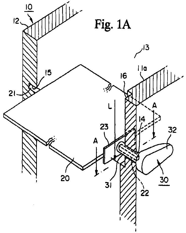
- Fig. 1 shows a first embodiment of a damper attaching structure according to the present invention. Fig. 1A is a principal portion cross sectional perspective view showing the arrangement at the rotation position with assembly completed; Fig. 1B is a cross sectional view taken on line A-A in Fig. 1A; Fig. 1C is a cross sectional view taken on line B-B in Fig. 1B.
- Fig. 2 is an exploded perspective view of Fig. 1.
- Fig. 3 is a view for explaining the damper attaching method according to the present invention, showing the principal part in the first step.
- Fig. 4 is a view for explaining the damper attaching method according to the present invention, showing the state after completion of the second step.
- Fig. 5 is a perspective view showing the structure of an air conditioning unit provided as a conventional example.
- Fig. 6 is a vertical cross sectional view of Fig. 5.
- Fig. 7 is a principal portion exploded perspective view showing the assembly structure of a damper shaft employing a divided casing.
- Fig. 8 is a cross sectional view showing a conventional example of the lever attaching structure for the rotational shaft.
- Fig. 9 is a cross sectional view showing another conventional example of the lever attaching structure for the rotational shaft.
-
- An embodiment of the damper attaching structure and damper attaching method according to the present invention will now be explained based on the figures.
- As shown in Fig. 1, the damper attaching structure comprises a
casing 10,wall members 11 and 12 of thecasing 10 disposed opposite one another, anopening 13 provided at the upper portion ofcasing 10, adamper 20, and alever 30 for rotating (opening/closing) thedamper 20. - Fig. 1A shows a completed assembly, in which both ends of the
damper 20, which is provided in between the opposing wall members of thecasing 10, are supported by thewall members 11 and 12 so as to enable free rotating of the damper. In other words, Fig. 1A shows the state in whichdamper 20 is at the center position of rotation. - A
shaft hole 14 is provided in the wall member 11 so as to pass through the wall member 11 and reach to the outside of the wall member 11. Ashaft fixing member 31 of thelever 30 explained below is rotatably inserted into theshaft hole 14. Thisshaft hole 14 has a larger cross section than that of a damperthin shaft member 22 of thedamper 20 explained below. Asupport hole 15 is provided to theother wall member 12 and functions as a bearing for adamper shaft member 21 which projects outward from thedamper 20. Note that thissupport hole 15 may be provided with an intermediate thickness as shown in the figure, or may be a hole passing through thewall member 12, according to various conditions such as the thickness of thewall member 12. - A
concave groove 16 is provided to the inner surface 11a of the wall member 11 to which thelever 30 is attached. Thisconcave groove 16 is rectangular in shape and is open at the upper end toward anopening 13. The width W of theconcave groove 16 is smaller than the length L in the vertical direction. A center line extending along the longitudinal direction of theconcave groove 16 is in the vertical direction, and theconcave groove 16 has a positional relationship with thedamper 20 such that it deviates by approximately 90° from the longitudinal plane of thedamper 20 when thedamper 20 is horizontal and at its center position of rotating. - The
damper 20 is a plate-shaped member provided with thedamper shaft member 21 and the damper thin shallmember 22 which are provided projecting out from either end of thedamper 20. Arectangular positioning plate 23 which functions as a positioning member is provided to the base of damperthin shaft member 22 on the damper side thereof, on the wall member 11 side to which thelever 30 is attached. Thispositioning plate 23 is designed to enter into the above-describedconcave groove 16. The length and width ofpositioning plate 23 are less than that ofconcave groove 16. It is preferable that the thickness ofpositioning plate 23 is less than the depth ofconcave groove 16. - In the embodiment shown in the figures, the damper
thin shaft member 22 is square in cross section. Since the objective is that the damperthin shaft member 22 and thelever 30 explained below are connected in a manner that enables torque transmission, not only a square but also polygonal shapes, such as a triangle or hexagon, which can be easily fabricated may also be employed. In other words, any of these shapes is acceptable for the cross sectional shape of the damperthin shaft member 22, provided that it will engage in the shaft hole on thelever 30 side and enable torque transmission. - The
shaft fixing member 31 projects out from a levermain body 32, so that thelever 30 is L-shaped. Thelever 30 is typically connected to a driving member via a link structure or the like not pictured in the figures. As shown in Fig. 1C, thisshaft fixing member 31 has a hollow cylindrical shape. An engaginghole 33 is formed at the center ofshaft fixing member 31 into which the damperthin shaft member 22 is inserted, joining in a manner so as to enable torque transmission. The outer peripheral surface ofshaft fixing member 31 is circular in cross section and is inserted into theshaft hole 14 of the wall member 11 in a manner so as to enable rotating. In other words, the engaginghole 33 in this embodiment has a square shape in cross section, equivalent to that of damperthin shaft member 22 so that the damperthin shaft member 22 can engage in the engaging hole without backlash. In addition, the circular cross sectional shape of theshaft fixing member 31 has the same diameter as theshaft hole 14, so thatshaft fixing member 31 inserts intoshaft hole 14 to enable smooth rotation without rattling. - The
lever 30 is designed to connect to the damperthin shaft member 22 that has been inserted into theshaft hole 14 by pushing thelever 30 from the outside of wall member 11 in the shaft direction. As a result, this offers excellent operability, and enables thelever 30 to be fixed in place with surety. - The operation of a damper attaching structure of the above-described design will now be explained based on the damper attaching method (sequence).
- Fig. 2 shows the state prior to assembly of the
damper 20. In the first step, thedamper 20 is inclined toward theconcave groove 16 which is formed to the inner surface 11a of wall member 11 and is continuous from casingopening 13. Namely, the end of damperthin shaft member 22 andpositioning plate 23, which is provided to the base of damperthin shaft member 22, are inclined downward, introduced intoconcave groove 16 and lowered by sliding along theconcave groove 16. As a result, damperthin shaft member 22 is inserted intoshaft hole 14 which opens in concave groove 16 (see Fig. 3). - The
concave groove 16 functions as a recess fordamper shaft member 21 and damperthin shaft member 22. Theshaft hole 14 is larger in cross section than that of damperthin shaft member 22, so that the inclined damperthin shaft member 22 is easy to insert. The presence ofconcave groove 16 is one reason why the damperthin shaft member 22 readily inserts into theshaft hole 14. - The second step after the damper
thin shaft member 22 is introduced into theshaft hole 14 is as follows. Thepositioning plate 23 is inserted into theconcave groove 16, and the shaft member ofdamper 20 is no longer inclined but is made level. Thepositioning plate 23 is tightly contacted to the opposing surface onconcave groove 16 by moving thedamper 20 toward the wall member 11 side where the lever is attached. - The lengths of
damper shaft member 21 and damperthin shaft member 22, and the depth ofconcave groove 16, are set so that the end surface ofdamper shaft member 21 can be introduced into thewall member 12 from itsinner surface 12a. By horizontally moving thedamper 20 toward theinner wall member 12, thedamper shaft member 21, which is circular in cross section, can be inserted into thesupport hole 15, which has the same circular cross section and is provided inwall member 12. This arrangement is shown in Fig. 4. The damperthin shaft member 22 is loose within theshaft hole 14 which has a larger cross sectional shape than that of damperthin shaft member 22. In addition, a part of or the whole of thepositioning plate 23 is within theconcave groove 16 and extends in the center direction of the casing at this point in time. Thedamper 20 is in the attachment position in this state. - Next, in the third step with the
positioning plate 23 being out from theconcave groove 16, thedamper 20 is rotated approximately 90° from the attachment position to the rotation position. In the embodiment shown in the figure, thedamper 20 is moved 90° from the attachment position in which the damper is vertical (see Fig. 4), to the rotation position in which it the damper is horizontal as shown in Fig. 1A. - The
damper 20 at the rotation position can oscillate employing the horizontal as the center of rotation. The length ofpositioning plate 23 is longer than the width W ofconcave groove 16 at this rotational center, so that positioningplate 23 intersects with the concave groove 16 (see Fig. 1B), and cannot be introduced into theconcave groove 16. As a result,positioning plate 23 and the inner surface 11a of wall member 11 come into contact, so that positioning along the shaft direction ofdamper 20 occurs. Accordingly, ifrectangular positioning plate 23 is not provided with a certain length dimension, then the limits within which thedamper 20 can oscillate are reduced. Since the angle formed between the center line ofpositioning plate 23 and the center line along the longitudinal direction ofconcave groove 16 is set to be around 90°, it is possible to increase the limits within whichdamper 20 can oscillate. - Next, the
shaft fixing member 31 which has the same circular shape as thecircular shaft hole 14 is inserted, and the damperthin shaft member 22 which is square in cross section engages with the engaginghole 33 in theshaft fixing member 31, the engaginghole 33 having the same cross sectional shape as the damperthin shaft member 22. The damperthin shaft member 22 and thelever 30 are connected in a manner that enables torque transmission, so that thedamper shaft member 21 and theshaft fixing member 31 can be smoothly rotated employing thesupport hole 15 and theshaft hole 14 as their respective bearings. - The operation to attach the
lever 30 can also be performed prior to moving thedamper 20 to the rotation position. Namely, in this case, thedamper 20 may be moved to the rotation position after attachment of thelever 30. - As described above, the damper attaching structure and the damper attaching method of the present invention enable the
damper 20 which is longer than thewall members 11 and 12 to be assembled inside the casing by inserting through theopening 13. As a result, it is not absolutely necessary to separate the casing at the attachment position for thedamper 20. Further, when attaching a plurality ofdampers 20, it may be the case that the directions for inserting and attaching the dampers are not the same. However, even in this type of situation, the present invention enables the dampers to be assembled without considering dividing the casing. - Provided that there is an opening, such as a casing connection opening or a suitably shaped outlet port, then the present invention can be easily executed by employing these openings effectively.
- Furthermore, in the preceding embodiments, the length of
positioning plate 23 is disposed so as to be level with thedamper 20. However, this may be suitably altered after taking into consideration the position of opening 13 and the oscillation limits fordamper 20. Namely, the length ofpositioning plate 23 may be set so that the angle between the long side ofpositioning plate 23 anddamper 20 is 90° or 60°, for example. - The damper attaching structure and damper attaching method the present invention provide the following effects.
- (1) Because an opening in the casing or the like can be employed to assemble the shaft member of the damper, the casing does not need to be divided. Thus, there is an improvement in the degree of design freedom permitted.
- (2) There is greater freedom with respect to placement of the damper, since it can be attached to a position where damper assembly could not be performed in the conventional design and method.
- (3) There is a great improvement in the operability of the assembly operation for the shaft fixing member in the lever which fixes the damper thin shaft member in a manner so as to enable torque transmission. Thus, it is possible to prevent damage to the casing or the like due to improper assembly.
-
Claims (7)
- A damper attaching structure in which both ends of a damper which is disposed between opposing wall members of a casing or the like are supported by the wall members in a manner so as to enable free rotation and the rotation operation of the damper is performed via a lever attached by a damper shaft on the outside of the wall member, the damper attaching structure comprising:a concave groove formed in the inner surface of the wall member and continuous with a casing opening;a positioning member provided at the base of the damper shaft on the damper side thereof;a shaft hole opening at the concave groove, which is larger than the cross section of the damper shaft;a shaft fixing member provided on the lever and rotatably inserted into the shaft hole; andan engaging hole into which the damper shaft member is inserted and which engages the damper shaft member to enable torque transmission;
wherein the concave groove is larger in shape than the positioning member, the positioning member is inserted into the concave groove at the attachment position of the damper, and the positioning member adjusts the position of the damper along the shaft direction by intersection with the concave groove at the rotation position of the damper. - A damper attaching structure according to claim 1, wherein the angle formed between the positioning member and a center line in the longitudinal direction of the concave groove at a position of the rotational center when the damper is operating is set to approximately 90°.
- A damper attaching structure according to claim 1 or 2, wherein the positioning member and the concave groove are the same shape and have a large aspect ratio so that the positioning member can be inserted into the concave groove.
- A damper attaching structure according to any one of claims 1 to 3, wherein the damper shaft and the engaging hole have the same polygonal shape in cross section.
- A damper attaching structure according to claim 4, wherein the lever is joined to the damper shaft which has been inserted into the shaft hole by pushing the lever in the direction of the shaft from the outside of the wall member.
- A damper attaching method, wherein both ends of a damper which is disposed between opposing wall members of a casing or the like are supported by the wall members in a manner so as to enable free rotation and the rotation operation of the damper is performed via a lever attached by a damper shaft on the outside of the wall member; the damper attaching structure comprising:a first step in which the end of the damper shaft and a positioning member, which is provided at the base of the damper shaft on the damper side thereof, are inclined downward and inserted into a concave groove that is formed in the inner surface of the wall member and is continuous with a casing opening, and the damper shaft is inserted into a shaft hole which opens at the concave groove and which is larger than the cross section of the damper shaft;a second step in which, after the positioning member has been inserted into the concave groove and the damper has been moved to the lever attachment side, the damper shaft which is circular in cross section is inserted into the shaft hole which is circular in cross section that is provided in the wall member opposite the wall member on the lever attachment side; anda third step in which, with the positioning member projecting out from the concave groove, the damper is rotated from the attachment position to the rotation position, while at the same time a shaft fixing member on the lever is inserted into the shaft hole in a manner so as to enable rotation and an engaging hole provided in the shaft fixing member is joined to the damper shaft so as to enable torque transmission.
- A damper attaching method according to claim 6, wherein the rotation of the damper from the attachment position to the rotation position in the third step is approximately 90°.
Applications Claiming Priority (3)
| Application Number | Priority Date | Filing Date | Title |
|---|---|---|---|
| JP11103344A JP2000289431A (en) | 1999-04-09 | 1999-04-09 | Mounting structure for dumper and mounting method for dumper |
| JP10334499 | 1999-04-09 | ||
| PCT/JP2000/002316 WO2000061396A1 (en) | 1999-04-09 | 2000-04-10 | Structure and method for mounting damper |
Publications (3)
| Publication Number | Publication Date |
|---|---|
| EP1086838A1 true EP1086838A1 (en) | 2001-03-28 |
| EP1086838A4 EP1086838A4 (en) | 2005-03-09 |
| EP1086838B1 EP1086838B1 (en) | 2005-12-07 |
Family
ID=14351535
Family Applications (1)
| Application Number | Title | Priority Date | Filing Date |
|---|---|---|---|
| EP00915453A Expired - Lifetime EP1086838B1 (en) | 1999-04-09 | 2000-04-10 | Structure and method for mounting damper |
Country Status (8)
| Country | Link |
|---|---|
| US (1) | US6520198B1 (en) |
| EP (1) | EP1086838B1 (en) |
| JP (1) | JP2000289431A (en) |
| CN (1) | CN1115262C (en) |
| AU (1) | AU738100B2 (en) |
| CA (1) | CA2334350A1 (en) |
| DE (1) | DE60024549D1 (en) |
| WO (1) | WO2000061396A1 (en) |
Cited By (3)
| Publication number | Priority date | Publication date | Assignee | Title |
|---|---|---|---|---|
| US9878596B2 (en) | 2011-09-28 | 2018-01-30 | Audi Ag | Air vent of a ventilation and heating module for motor vehicles with switching between a spot position and a diffuse position |
| WO2020144174A1 (en) * | 2019-01-10 | 2020-07-16 | Dr. Schneider Kunststoffwerke Gmbh | Bearing arrangement and air vent having such a bearing arrangement |
| WO2020200922A1 (en) * | 2019-04-04 | 2020-10-08 | Schneider Kunststoffwerke Gmbh | Coupling arrangement between an air-guiding element and a drive device, and air vent having a lamella arrangement |
Families Citing this family (17)
| Publication number | Priority date | Publication date | Assignee | Title |
|---|---|---|---|---|
| JP2002309945A (en) * | 2001-04-17 | 2002-10-23 | Toyota Motor Corp | Intake system for internal combustion engine |
| JP3858712B2 (en) * | 2002-01-31 | 2006-12-20 | 株式会社デンソー | Air conditioner for vehicles |
| JP4432622B2 (en) * | 2004-05-31 | 2010-03-17 | 株式会社デンソー | Air conditioner for vehicles |
| JP2005349942A (en) * | 2004-06-10 | 2005-12-22 | Denso Corp | Air conditioner for vehicle |
| US7118092B2 (en) * | 2005-03-08 | 2006-10-10 | Delphi Technologies, Inc. | Method and apparatus for assembling a vane-type valve |
| GB0516500D0 (en) * | 2005-08-11 | 2005-09-14 | Active Technologies Ltd | Valve assembly |
| KR101511513B1 (en) * | 2007-10-09 | 2015-04-13 | 한라비스테온공조 주식회사 | Door for air conditioner in vehicle |
| KR200466554Y1 (en) | 2011-04-29 | 2013-04-24 | 김도수 | A barb type damper |
| KR101428936B1 (en) * | 2013-08-06 | 2014-08-08 | 주식회사 니프코코리아 | Air vent for automobile |
| DE102016219263A1 (en) * | 2015-10-06 | 2017-04-06 | Hanon Systems | Vehicle air conditioning |
| DE102016001902B3 (en) * | 2016-02-18 | 2017-03-30 | Audi Ag | Device for adjusting an air flow and ventilation device for a vehicle |
| JP6735906B2 (en) * | 2017-03-29 | 2020-08-05 | 三菱電機株式会社 | Ventilation fan for duct |
| JP2018199443A (en) * | 2017-05-29 | 2018-12-20 | カルソニックカンセイ株式会社 | Air-conditioning unit link module and air-conditioning unit |
| CN107490167B (en) * | 2017-08-14 | 2019-10-11 | 安徽工程大学 | A kind of positioning device for wind deflector of air conditioner indoor unit shell |
| DE102018121470A1 (en) * | 2018-09-04 | 2020-03-05 | Dr. Schneider Kunststoffwerke Gmbh | Bearing component and bearing arrangement with a bearing component |
| CN113483402B (en) * | 2021-07-23 | 2022-11-18 | 青岛海尔空调器有限总公司 | Fresh air device, air conditioner internal unit and air conditioner |
| CN114194003A (en) * | 2022-01-25 | 2022-03-18 | 泰铂(上海)环保科技股份有限公司 | Air inlet of vehicle air conditioner, vehicle comprising same and air conditioning system |
Citations (5)
| Publication number | Priority date | Publication date | Assignee | Title |
|---|---|---|---|---|
| GB1550836A (en) * | 1976-08-23 | 1979-08-22 | Delanair Ltd | Pivot valves |
| FR2522591A1 (en) * | 1982-03-04 | 1983-09-09 | Sueddeutsche Kuehler Behr | Housing for vehicle heater - contains openings which receive ends of rotatable one piece flap |
| JPS5962777A (en) * | 1982-10-01 | 1984-04-10 | Nissan Motor Co Ltd | Door structure for car air-conditioner |
| DE4422537A1 (en) * | 1994-06-28 | 1996-01-04 | Behr Gmbh & Co | Air intake channel air flap |
| DE19741975A1 (en) * | 1997-09-23 | 1999-03-25 | Valeo Gmbh Klimasysteme | Distribution flap |
Family Cites Families (10)
| Publication number | Priority date | Publication date | Assignee | Title |
|---|---|---|---|---|
| JPS6111413U (en) | 1984-06-27 | 1986-01-23 | 株式会社デンソー | Air flow switching valve |
| JPH0350351Y2 (en) * | 1986-12-23 | 1991-10-28 | ||
| JPH0217414A (en) * | 1988-07-06 | 1990-01-22 | Fanuc Ltd | Eccentricity adjusting method of code disk |
| JPH0714012Y2 (en) | 1988-07-21 | 1995-04-05 | 株式会社ゼクセル | Duct case connection structure |
| JPH06111413A (en) * | 1992-09-24 | 1994-04-22 | Funai Electric Co Ltd | Video recording device for video timer |
| JPH06137664A (en) * | 1992-10-28 | 1994-05-20 | Nippon Plast Co Ltd | Pivoting body mounting structure in air-conditioning air passage |
| US5348272A (en) * | 1993-03-31 | 1994-09-20 | Combustion Engineering, Inc. | Damper with improved drive shaft bearing assembly |
| US5785077A (en) * | 1996-11-15 | 1998-07-28 | Rice; Donald C. | Easily replaceable valve |
| CN2297664Y (en) * | 1997-06-05 | 1998-11-18 | 隋永财 | Insulating damper for hot kang |
| JPH11103344A (en) | 1997-09-26 | 1999-04-13 | Hitachi Ltd | Speech recording method |
-
1999
- 1999-04-09 JP JP11103344A patent/JP2000289431A/en active Pending
-
2000
- 2000-04-10 AU AU36755/00A patent/AU738100B2/en not_active Ceased
- 2000-04-10 CN CN00800532A patent/CN1115262C/en not_active Expired - Fee Related
- 2000-04-10 WO PCT/JP2000/002316 patent/WO2000061396A1/en active IP Right Grant
- 2000-04-10 EP EP00915453A patent/EP1086838B1/en not_active Expired - Lifetime
- 2000-04-10 CA CA002334350A patent/CA2334350A1/en not_active Abandoned
- 2000-04-10 DE DE60024549T patent/DE60024549D1/en not_active Expired - Lifetime
- 2000-04-10 US US09/719,151 patent/US6520198B1/en not_active Expired - Fee Related
Patent Citations (5)
| Publication number | Priority date | Publication date | Assignee | Title |
|---|---|---|---|---|
| GB1550836A (en) * | 1976-08-23 | 1979-08-22 | Delanair Ltd | Pivot valves |
| FR2522591A1 (en) * | 1982-03-04 | 1983-09-09 | Sueddeutsche Kuehler Behr | Housing for vehicle heater - contains openings which receive ends of rotatable one piece flap |
| JPS5962777A (en) * | 1982-10-01 | 1984-04-10 | Nissan Motor Co Ltd | Door structure for car air-conditioner |
| DE4422537A1 (en) * | 1994-06-28 | 1996-01-04 | Behr Gmbh & Co | Air intake channel air flap |
| DE19741975A1 (en) * | 1997-09-23 | 1999-03-25 | Valeo Gmbh Klimasysteme | Distribution flap |
Non-Patent Citations (2)
| Title |
|---|
| PATENT ABSTRACTS OF JAPAN vol. 008, no. 166 (M-314), 2 August 1984 (1984-08-02) & JP 59 062777 A (NISSAN JIDOSHA KK; others: 01), 10 April 1984 (1984-04-10) * |
| See also references of WO0061396A1 * |
Cited By (4)
| Publication number | Priority date | Publication date | Assignee | Title |
|---|---|---|---|---|
| US9878596B2 (en) | 2011-09-28 | 2018-01-30 | Audi Ag | Air vent of a ventilation and heating module for motor vehicles with switching between a spot position and a diffuse position |
| WO2020144174A1 (en) * | 2019-01-10 | 2020-07-16 | Dr. Schneider Kunststoffwerke Gmbh | Bearing arrangement and air vent having such a bearing arrangement |
| US11884130B2 (en) | 2019-01-10 | 2024-01-30 | Dr. Schneider Kunststoffwerke Gmbh | Bearing arrangement and air vent having such a bearing arrangement |
| WO2020200922A1 (en) * | 2019-04-04 | 2020-10-08 | Schneider Kunststoffwerke Gmbh | Coupling arrangement between an air-guiding element and a drive device, and air vent having a lamella arrangement |
Also Published As
| Publication number | Publication date |
|---|---|
| AU3675500A (en) | 2000-11-14 |
| JP2000289431A (en) | 2000-10-17 |
| CA2334350A1 (en) | 2000-10-19 |
| AU738100B2 (en) | 2001-09-06 |
| DE60024549D1 (en) | 2006-01-12 |
| CN1300255A (en) | 2001-06-20 |
| CN1115262C (en) | 2003-07-23 |
| EP1086838B1 (en) | 2005-12-07 |
| US6520198B1 (en) | 2003-02-18 |
| WO2000061396A1 (en) | 2000-10-19 |
| EP1086838A4 (en) | 2005-03-09 |
Similar Documents
| Publication | Publication Date | Title |
|---|---|---|
| EP1086838B1 (en) | Structure and method for mounting damper | |
| JP4733889B2 (en) | Bearing device | |
| KR19990077794A (en) | Air conditioner | |
| JP4235205B2 (en) | Harness exterior member and harness routing structure using the same | |
| CN115289535A (en) | Indoor unit of air conditioner | |
| KR20000013265A (en) | Door plate driving device of vehicle air conditioner | |
| JP4262579B2 (en) | Air conditioner | |
| CN107650617B (en) | Air conditioner for vehicle | |
| GB2368388A (en) | Damper attachment means | |
| JP2005147628A (en) | Air conditioner | |
| US5803578A (en) | Headlamp mounting system | |
| MXPA00012276A (en) | Structure and method for mounting damper | |
| JP3419981B2 (en) | Shift lever device | |
| EP3831633A2 (en) | Air introducing mechanism and vehicle | |
| JP3858973B2 (en) | Vehicle louver | |
| JP3957930B2 (en) | Sliding door device | |
| EP1262646A2 (en) | Valve apparatus | |
| JP2003127657A (en) | Wind direction adjustment device | |
| JPH0650244Y2 (en) | Door mounting structure for air conditioners | |
| JP2020163905A (en) | Air-conditioning register | |
| JP4186597B2 (en) | Air conditioner | |
| KR970006654Y1 (en) | Door link assembly of an airconditioner of a vehicle | |
| KR200151005Y1 (en) | Air-control case for a vehicle | |
| WO2016111337A1 (en) | Coaxial structure door device and method for producing coaxial structure door device | |
| EP2513522B1 (en) | Gear shift system |
Legal Events
| Date | Code | Title | Description |
|---|---|---|---|
| PUAI | Public reference made under article 153(3) epc to a published international application that has entered the european phase |
Free format text: ORIGINAL CODE: 0009012 |
|
| 17P | Request for examination filed |
Effective date: 20001208 |
|
| AK | Designated contracting states |
Kind code of ref document: A1 Designated state(s): AT BE CH CY DE DK ES FI FR GB GR IE IT LI LU MC NL PT SE |
|
| RBV | Designated contracting states (corrected) |
Designated state(s): DE FR GB IT NL |
|
| A4 | Supplementary search report drawn up and despatched |
Effective date: 20050126 |
|
| GRAP | Despatch of communication of intention to grant a patent |
Free format text: ORIGINAL CODE: EPIDOSNIGR1 |
|
| GRAS | Grant fee paid |
Free format text: ORIGINAL CODE: EPIDOSNIGR3 |
|
| GRAA | (expected) grant |
Free format text: ORIGINAL CODE: 0009210 |
|
| AK | Designated contracting states |
Kind code of ref document: B1 Designated state(s): DE FR GB IT NL |
|
| PG25 | Lapsed in a contracting state [announced via postgrant information from national office to epo] |
Ref country code: IT Free format text: LAPSE BECAUSE OF FAILURE TO SUBMIT A TRANSLATION OF THE DESCRIPTION OR TO PAY THE FEE WITHIN THE PRESCRIBED TIME-LIMIT;WARNING: LAPSES OF ITALIAN PATENTS WITH EFFECTIVE DATE BEFORE 2007 MAY HAVE OCCURRED AT ANY TIME BEFORE 2007. THE CORRECT EFFECTIVE DATE MAY BE DIFFERENT FROM THE ONE RECORDED. Effective date: 20051207 Ref country code: NL Free format text: LAPSE BECAUSE OF FAILURE TO SUBMIT A TRANSLATION OF THE DESCRIPTION OR TO PAY THE FEE WITHIN THE PRESCRIBED TIME-LIMIT Effective date: 20051207 |
|
| REG | Reference to a national code |
Ref country code: GB Ref legal event code: FG4D |
|
| REF | Corresponds to: |
Ref document number: 60024549 Country of ref document: DE Date of ref document: 20060112 Kind code of ref document: P |
|
| PG25 | Lapsed in a contracting state [announced via postgrant information from national office to epo] |
Ref country code: DE Free format text: LAPSE BECAUSE OF FAILURE TO SUBMIT A TRANSLATION OF THE DESCRIPTION OR TO PAY THE FEE WITHIN THE PRESCRIBED TIME-LIMIT Effective date: 20060308 |
|
| NLV1 | Nl: lapsed or annulled due to failure to fulfill the requirements of art. 29p and 29m of the patents act | ||
| PLBE | No opposition filed within time limit |
Free format text: ORIGINAL CODE: 0009261 |
|
| STAA | Information on the status of an ep patent application or granted ep patent |
Free format text: STATUS: NO OPPOSITION FILED WITHIN TIME LIMIT |
|
| 26N | No opposition filed |
Effective date: 20060908 |
|
| EN | Fr: translation not filed | ||
| PGFP | Annual fee paid to national office [announced via postgrant information from national office to epo] |
Ref country code: GB Payment date: 20070404 Year of fee payment: 8 |
|
| PG25 | Lapsed in a contracting state [announced via postgrant information from national office to epo] |
Ref country code: FR Free format text: LAPSE BECAUSE OF FAILURE TO SUBMIT A TRANSLATION OF THE DESCRIPTION OR TO PAY THE FEE WITHIN THE PRESCRIBED TIME-LIMIT Effective date: 20070126 |
|
| PG25 | Lapsed in a contracting state [announced via postgrant information from national office to epo] |
Ref country code: FR Free format text: LAPSE BECAUSE OF FAILURE TO SUBMIT A TRANSLATION OF THE DESCRIPTION OR TO PAY THE FEE WITHIN THE PRESCRIBED TIME-LIMIT Effective date: 20051207 |
|
| GBPC | Gb: european patent ceased through non-payment of renewal fee |
Effective date: 20080410 |
|
| PG25 | Lapsed in a contracting state [announced via postgrant information from national office to epo] |
Ref country code: GB Free format text: LAPSE BECAUSE OF NON-PAYMENT OF DUE FEES Effective date: 20080410 |