EP1085840B1 - Microkeratome pour l'execution de resections corneennes - Google Patents
Microkeratome pour l'execution de resections corneennes Download PDFInfo
- Publication number
- EP1085840B1 EP1085840B1 EP00922122A EP00922122A EP1085840B1 EP 1085840 B1 EP1085840 B1 EP 1085840B1 EP 00922122 A EP00922122 A EP 00922122A EP 00922122 A EP00922122 A EP 00922122A EP 1085840 B1 EP1085840 B1 EP 1085840B1
- Authority
- EP
- European Patent Office
- Prior art keywords
- cutting
- cutting head
- microkeratome
- guide ring
- blade
- Prior art date
- Legal status (The legal status is an assumption and is not a legal conclusion. Google has not performed a legal analysis and makes no representation as to the accuracy of the status listed.)
- Expired - Lifetime
Links
Images


Classifications
-
- A—HUMAN NECESSITIES
- A61—MEDICAL OR VETERINARY SCIENCE; HYGIENE
- A61F—FILTERS IMPLANTABLE INTO BLOOD VESSELS; PROSTHESES; DEVICES PROVIDING PATENCY TO, OR PREVENTING COLLAPSING OF, TUBULAR STRUCTURES OF THE BODY, e.g. STENTS; ORTHOPAEDIC, NURSING OR CONTRACEPTIVE DEVICES; FOMENTATION; TREATMENT OR PROTECTION OF EYES OR EARS; BANDAGES, DRESSINGS OR ABSORBENT PADS; FIRST-AID KITS
- A61F9/00—Methods or devices for treatment of the eyes; Devices for putting-in contact lenses; Devices to correct squinting; Apparatus to guide the blind; Protective devices for the eyes, carried on the body or in the hand
- A61F9/007—Methods or devices for eye surgery
- A61F9/013—Instruments for compensation of ocular refraction ; Instruments for use in cornea removal, for reshaping or performing incisions in the cornea
-
- A—HUMAN NECESSITIES
- A61—MEDICAL OR VETERINARY SCIENCE; HYGIENE
- A61F—FILTERS IMPLANTABLE INTO BLOOD VESSELS; PROSTHESES; DEVICES PROVIDING PATENCY TO, OR PREVENTING COLLAPSING OF, TUBULAR STRUCTURES OF THE BODY, e.g. STENTS; ORTHOPAEDIC, NURSING OR CONTRACEPTIVE DEVICES; FOMENTATION; TREATMENT OR PROTECTION OF EYES OR EARS; BANDAGES, DRESSINGS OR ABSORBENT PADS; FIRST-AID KITS
- A61F9/00—Methods or devices for treatment of the eyes; Devices for putting-in contact lenses; Devices to correct squinting; Apparatus to guide the blind; Protective devices for the eyes, carried on the body or in the hand
- A61F9/007—Methods or devices for eye surgery
- A61F9/00709—Instruments for removing foreign bodies
-
- A—HUMAN NECESSITIES
- A61—MEDICAL OR VETERINARY SCIENCE; HYGIENE
- A61F—FILTERS IMPLANTABLE INTO BLOOD VESSELS; PROSTHESES; DEVICES PROVIDING PATENCY TO, OR PREVENTING COLLAPSING OF, TUBULAR STRUCTURES OF THE BODY, e.g. STENTS; ORTHOPAEDIC, NURSING OR CONTRACEPTIVE DEVICES; FOMENTATION; TREATMENT OR PROTECTION OF EYES OR EARS; BANDAGES, DRESSINGS OR ABSORBENT PADS; FIRST-AID KITS
- A61F9/00—Methods or devices for treatment of the eyes; Devices for putting-in contact lenses; Devices to correct squinting; Apparatus to guide the blind; Protective devices for the eyes, carried on the body or in the hand
- A61F9/007—Methods or devices for eye surgery
- A61F9/013—Instruments for compensation of ocular refraction ; Instruments for use in cornea removal, for reshaping or performing incisions in the cornea
- A61F9/0133—Knives or scalpels specially adapted therefor
Definitions
- the present invention relates to medical instruments for performing eye surgery to correct irregularities of the cornea. More particularly, the present invention relates to mechanical instruments known as microkeratomes and the cutting blades utilized thereby.
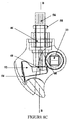
- the first microkeratome for performing corneal resections was developed in 1962 by the Doctor Jose I. Barraquer, and is shown generally in FIG. 1A.
- This microkeratome includes a guide ring which is fixed to an ocular globe, or eyeball, with the aid of a partial vacuum applied through the guide ring.
- the guide ring immobilizes the ocular globe, maintains the tension of the globe, and aids in regulating the diameter of the corneal resection.
- a portion of the microkeratome called a cutting head is supported within a channel in the guide ring for guided linear movement of the microkeratome across the ring by the surgeon.
- the cutting head carries a cutting blade that is oscillated by a motor-driven eccentric transverse the channel as the instrument is moved through the cutting path defined by the channel.
- the cutting head carries a removable, lower planar member that compresses the ocular globe ahead of the oscillating blade, to permit the blade to cut a lamella having a lower surface that is parallel to the surface of the cornea that is compressed by the planar member.
- the planar member is interchangeable with similar planar members of differing thicknesses, so as to vary the thickness of the resectioned corneal "disk.”
- the Barraquer microkeratome Numerous variations on the Barraquer microkeratome have been made since 1962, including the apparatus that is the subject of U.S. Patent No. 4,662,370 assigned to Carl-Zeiss-Lite of Germany.
- the '370 patent describes a microkeratome having interchangeable inserts with convex, concave, and planar surfaces that engage and compress the cornea for producing a corneal resection of predetermined form and curvature.
- the inserts are set within a stationary planar member that is fixed to the guide ring.
- the cutting blade is moved through a cutting path parallel to the planar member defined by a gap between the planar member and the guide ring, and oscillates transverse the path.
- the apparatus of the '370 patent lacks means for controlling, or automating the rate of movement by the cutting head across the guide ring, and is therefore prone to binding up in the corneal tissue, or otherwise producing imprecise resections under unsteady progress by the surgeon's hand. Furthermore, there is no apparent means for changing the depth or thickness of the corneal resection. Also, this apparatus is limited to use in lamellar keratectomies (excision of a corneal section), as opposed to lamellar keratotomies (incision through the cornea).
- LASIK Laser Intrastromal Keratomileusis
- the microkeratome of the '726 and '421 patents include a forward planar member in the lower portion of the cutting head that is interchangeable with similar planar members of varying thicknesses.
- a slotted portion of the cutting head extends substantially forward of the cutting blade to receive the planar member.
- the vertical nasal hinge has at least two deficiencies. First, the corneal disk resulting from the LASIK, or other procedure, will be vertically displaced after surgery, and/or pleated to some extent by the opening and closing of the upper eyelid. Second, the formation of a vertical nasal hinge on the corneal disk increases the likelihood of accidental ablation of the hinge during the correction of an astigmatism, which is typically performed with vertical cutting motions across a major diameter ofthe cornea.
- planar member, or plaque, described in the '726 patent is designed to substantially compress the entire cornea at any one time. Such action produces unnecessarily high intraocular pressure, which unduly stresses the eye and could result in complications during surgery.
- Another problem with known systems such as the microkeratome described in U.S. Patent No. 5,624,456, relates to the manner in which the cutting head is brought into contact with the corneal surface. More specifically, the microkeratome of the '456 patent induces movement of a cutting blade through a flat plane which is defined, by necessity, to clear the patient's ocular structure. For purposes of discussion, this plane may be considered to be a horizontal plane since the patient's head will be more or less horizontal during the procedure. In order for the cutting blade to intersect the cornea, the eye must be pulled outwardly over the ocular structures so as to place a portion of the cornea above the horizontal plane. This creates a risk of suction loss between the surgical guide ring and the eye during the operation, with potentially severe consequences.
- EP 0 432 325 A1 discloses a scalpel having a disposable blade and a handle for retaining the blade, the disposable blade is provided on its rear end portion with at least one tongue piece which can be held with a tool such as a needle holder or forceps. The replacement of the blade with another can be carried out while holding the tongue piece with the tool even in the midst of the surgical operation, so that the blades of various types different in shape can be properly used for each purpose.
- the objects and advantages of the present invention are achieved by an improved microkeratome for performing a lamellar keratotomy of an ocular globe.
- the microkeratome includes a guide ring assembly for placement on the ocular globe and means for temporarily fixing the guide ring to the ocular globe.
- a cutting head contains a cutting blade having an arcuate cutting edge suitable for corneal resections.
- a vertical support assembly is connected to the guide ring and supports the cutting head for rotation about a horizontal axis such that rotation of the cutting head about the horizontal axis moves the cutting blade along an arcuate cutting path into engagement with the cornea of the ocular globe, whereby the arcuate cutting edge of the cutting blade cuts a substantially rounded corneal disk.
- the cutting blade may include a substantially rectangular plate having one of its edges sharpened for cutting.
- the plate has a smooth, continuous bend therein making the cutting edge arcuately shaped.
- the cutting blade preferably includes steel, and may comprise a stainless steel alloy. An opening is provided in the plate ofthe cutting blade for engagement by a blade-holding member of the microkeratome.
- the microkeratome also includes means for rotating the cutting head about the horizontal axis to move the cutting blade at least partially through the cornea to create a corneal flap during a lamellar keratotomy.
- the cutting head includes an opening providing access to the support shaft.
- the rotating means include a housing adapted for connection to the cutting head at the opening therein.
- An output shaft is rotatably carried within the housing and has an outer portion extending from the housing for passage through the opening in the cutting head and engagement with the support shaft when the housing is connected to the cutting head.
- Means are carried within the housing for applying a torque to the output shaft, whereby the application of torque from the torque applying means to the output shaft induces rotation of the cutting head and the housing about the support shaft at a controlled speed.
- the cutting head include a support shaft extending laterally therethrough equipped with lateral support members on either end of the support shaft that extend from opposing sides of said cutting head for engagement with the vertical support assembly. Still further, it is preferred that the cutting head include means for oscillating the cutting blade back and forth through an arcuate path transverse the cutting head to facilitate a smooth incision by the cutting blade.
- the vertical support assembly preferably includes a pair of members extending upwardly from the guide ring 180° apart from each other.
- the vertical support assembly includes a pair of opposing members separated 180° apart from each other in respect to the guide ring by a lateral support arm, the lateral support arm being supported above the guide ring by a vertical support arm extending upwardly from the guide ring.
- a method of performing corneal resections for a lamellar keratotomy including the step of supporting a cutting head carrying a cutting blade having an arcuate cutting edge for rotation about a horizontal axis elevated above the patient's eye, and inducing rotation of the cutting head about the horizontal axis to move the cutting blade through a pendular cutting path that intersects the cornea.
- the cutting head is supported by fixing guide ring to an ocular globe about the globe's cornea so that the cornea extends through and above the guide ring.
- the guide ring includes a support system extending upwardly therefrom, and the cutting head includes a support shaft adapted for alignment with the horizontal axis and constrained against rotation about the horizontal axis by the support system when the support shaft is placed in engagement with the support system.
- Rotation of the cutting head is induced by operating a motor to apply a torque to the constrained support shaft to drive the cutting head and move the cutting blade through a pendular cutting path that intersects the cornea. The movement of the cutting blade is stopped at a predetermined point along the cutting path whereby a hinged corneal cap is formed.
- a method is described defined by the steps of fixing a guide ring to an ocular globe about the globe's cornea so that at least a portion of the cornea extends through and above the guide ring, and inducing rotation of a cutting head carrying a cutting blade about a horizontal axis elevated above the guide ring, whereby rotation of the cutting head moves the cutting blade through a pendular cutting path that intersects the portion of the cornea extending above the guide ring.
- the cutting blade may have either an arcuate cutting edge whereby the rotation of the cutting head produces a substantially round-shaped corneal disk, or a straight cutting edge whereby the rotation of the cutting head produces a substantially oval-shaped corneal disk.
- the arcuate cutting edge may be shaped so as to produce a substantially oval-shaped corneal disk, as appropriate for the desired correction.
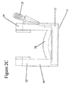
- FIGS. 1C-9D illustrate various embodiments of a microkeratome for performing a lamellar keratotomy or a lamellar keratectomy of an ocular globe, in accordance with the present invention.
- the instrument is suitable to perform surgery of myopia (nearsightedness), hyperopia (farsightedness), astigmatism and presbyopia (corneal stiffening due to aging), and is particularly well-suited to perform cuts other than temporo-nasal, such as bottom, upper, and oblique cuts.
- microkeratome 10 generally includes guide ring assembly 12 adapted for placement directly on a patient's eye or ocular globe such that the globe's cornea protrudes therethrough.
- Means, including suction conduit 14, are provided for temporarily fixing guide ring 12 to the ocular globe.
- Cutting head 16 containing a cutting blade suitable for corneal resections is also provided, and will be discussed in greater detail below.
- Vertical support assembly 18 is connected to, or alternatively forms a part of, guide ring 12 and supports cutting head 16 for rotation about horizontal axis A-A elevated above guide ring 12 such that rotation of cutting head 16 about horizontal axis A-A moves a cutting blade (described below) along an arcuate cutting path into engagement with the cornea of the patient's ocular globe.
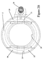
- FIGS. 2A-2D illustrate guide ring 12 and vertical support assembly 18 in greater detail.
- vertical support assembly 18 includes a pair of arm members 20, 22 extending upwardly from guide ring 12 and spaced 180° apart from each other.
- arm members 20, 22 bound arcuate surface 24 which contains circular opening 26 permitting passage of the patient's cornea.
- Arm members 20 and 22 are further equipped with slots 21 and 23, respectively, for rotating cutting head 16 about axis A-A, as will be described further below.
- Guide ring 12 is further equipped with vacuum adapter 28 for connection to suction conduit 14 shown in FIG. 1.
- the lower portion of guide ring 12 defines suction ring 13 which conducts partial vacuum (below atmospheric) pressure delivered through suction conduit 14 and vacuum adapter 28 from a vacuum pump (not shown) to the patient's ocular globe or eyeball. In this manner, the eyeball is immobilized relative to the guide ring and the intraocular pressure is regulated.
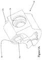
- Cutting head 16 is shown in greater detail in FIGS. 4A-5B.
- the cutting head includes support shaft 30 which extends laterally through body 32.
- Support shaft 30 is equipped with lateral support members 31, 33 on either end thereof that extend from opposing sides of cutting head body 32 for engagement with slots 21, 23, respectively, of upwardly extending arm members 20, 22 of the support assembly, as seen in FIGS. 2A-2B.
- lateral support members 31, 33 of support shaft 30 are square-shaped and sized for closely fitting within U-shaped square slots 21, 23 defined by arm members 20, 22 of vertical support assembly 18. In this manner, support shaft 30 of cutting head 16 is placed in static engagement with arm members 20, 22 whereby the support shaft is constrained against rotation relative to vertical support assembly 18 and guide ring 12.
- FIG. 5A illustrates an alternative embodiment wherein support shaft 30 terminates in triangular-shaped lateral support members 31a, 33a for static engagement (not shown) with the upwardly extending arm members of the vertical support assembly.
- the arm members of this embodiment will define V-shaped slots sized for a close fit with support members 31a, 33a.
- FIG. 5B illustrates another alternative embodiment wherein support shaft 30 terminates in circular-shaped lateral support members 31b, 33b for rotational engagement (not shown) with the upwardly extending members of the vertical support assembly whereby the support shaft is free to rotate relative to the upwardly extending arm members.
- the arm members will define semi-circular openings for a close fit with support members 31b, 33b.
- cutting head body 32 shown in FIGS. 4A-5B is a uni-body of cast construction having a side opening therein for moving a blade and blade holder assembly through cavity 34.
- cutting head 32 includes substantially cylindrical opening 36 of variable bore size and depth, as well as lateral cylindrical bore 38 therein. Opening 36 is formed with either threads or a mechanical slot for engagement with complementary threads or mechanical key on handle 40 (see FIG. 1) of microkeratome 10. The action of a drive motor carried within handle 40 in one embodiment of the present invention will be explained below.
- Lateral bore 38 is sized for accepting shaft 30 having outer threads 42, or alternatively mechanical teeth 42, and support members 31, 33, which are square-shaped as indicated in FIGS. 4A and 4B.
- These support members may alternatively be triangular as seen at 31a and 33a in FIG. 5A, circular as seen at 31b and 33b in FIG. 5B, or star-shaped as seen at 31c and 31d in FIGS. 6A and 6B.
- the cutting head may be further equipped with upper and lower portions connected by a hinge (not shown) that permits the cutting head to be opened for accessing the cutting blade.
- the cutting head may be equipped with first and second laterally connected portions for the same purpose.
- Microkeratome 10 further includes means for rotating cutting head 16 about elevated horizontal axis A-A to move the cutting blade at least partially through the cornea to create a corneal flap during a lamellar keratotomy.
- the rotating means includes, in at least one embodiment of the present invention, means for inducing oscillatory motion in the cutting blade of the cutting head that is transverse the cutting path defined by rotation of the cutting head about the elevated horizontal axis.
- electric drive motor 44 or other similar means provides the torque necessary for rotating input shaft 46, which terminates outside the motor housing in small eccentric projection or pin 48.
- torque from drive motor 44 is applied to shaft 46 to effect a desired rotation speed of cutting head 16, as will be explained below, as well as to rotate pin 48.
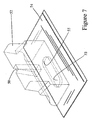
- the assembly of drive motor 44 and input shaft 46 is mounted within handle 40 in such a manner that, when handle 40 is engaged with cutting head 16, eccentric pin 48 engages slot 50 of blade holder 52, seen in FIG. 7, to transmit an oscillatory motion to blade 54 that corresponds to the speed of the motor.
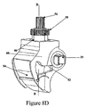
- This arrangement of blade holder 52, blade 54, and eccentric pin 48 is shown in FIGS. 8A-8D.
- Cutting blade 54 is rectangular and includes elongated slot 55 that closely fits over projection 53 of blade holder 52 to mount the blade to the blade holder within the cutting head.
- blade holder 54 has vertical rectangular groove 50 therein for engagement by eccentric pin 48 of shaft 46 through cylindrical cavity 36 of the cutting head. As the eccentric pin is rotated off-center by shaft 46, it induces back-and-forth lateral motion of blade holder 52 within cavity 34 of the cutting head. This lateral motion results in the oscillation of blade 54.
- Rotation of input shaft 46 also rotates external threads 60 thereon about axis B-B, which, in the embodiment of FIGS. 8A-8D, induces rotation of cutting head 16 about axis A-A. More particularly, threaded portion 60 of shaft 46 engages outer threads 62 of shaft 30. Since shaft 30 is constrained against rotation by the engagement of support members 31 and 33 in openings 21 and 23, respectively, of support assembly 18, the torque of input shaft 46 induces the input shaft, motor 44, handle 40, and cutting head 16 to all rotate as a unit about axis A-A. In this manner, the cutting blade (described below) cuts at least partially through the cornea to perform the desired lamellar keratotomy.
- Threaded sections 60 and 62 may be of various diameters so as to provide for speed adjustments therebetween, in other words, step-down, step-up, or constant speed, between the rate of blade oscillation and the rate of cutting head rotation about axis A-A.
- these rates may be 1: 1, or the speed of the blade oscillation may be designed to be faster or slower than the speed of cutting head rotation about axis A-A.
- gears 56, 58 mounted to shaft 46 may be utilized for such speed control purposes.
- the means for rotating cutting head 16 will include a handle (not unlike handle 40) connected to the cutting head, which is adapted for gripping by a surgeon to manually induce rotation of the cutting head about the elevated horizontal axis.
- this manually driven embodiment can also be equipped with drive motor 44 for inducing the transverse oscillatory motion of blade 54 as the blade is moved through the cornea. Such oscillatory motion promotes a smooth, continuous cut through the corneal tissue.
- the microkeratome may further include a stop means (not shown) for limiting the range through which the cutting blade is carried by said cutting head so as to define a corneal hinge during a lamellar keratotomy.
- a stop means for limiting the range through which the cutting blade is carried by said cutting head so as to define a corneal hinge during a lamellar keratotomy.
- the increased load applied to drive motor 21 will trigger a control circuit to stop and/or reverse the direction of motor 21 as desirable for completing the lamellar keratotomy.
- the microkeratome may also be equipped with an adjustable float head (not shown) connected to the cutting head for at least partially compressing the cornea ahead of the cutting blade so as to set the corneal resection to the desired shape and thickness.
- the adjustable float head preferably includes a pair of substantially parallel float arms, and a float having a multi-sided cross-section with multiple respective faces and being supported for rotation between the float arms about a journal that extends through the float.
- the float head may be equipped with indicia thereon for indicating the resection thickness provided by the selected face.
- each of the faces of the float be spaced at different distances from the journal, whereby the thickness of the corneal resection is varied by rotation of the float until the desired face is in position to compress the cornea.
- the float may be equipped in various ways, such as by having at least one arcuate face and/or one oblique face, whereby different corneal lenticular resections are performed by compressing the cornea with the respective face.
- the structure of the float head assembly is described more completely in U.S. Patent No. 5,980,543.
- the present invention will permit the orientation of microkeratome 10 in any direction without colliding with the annexes of the eye.
- the cutting head assembly permits cutting blade 54 to be moved beneath a cutting plane that would be defined by the upper surface of a typical flat-disc type guide ring.
- the vertical support assembly also dispenses with the need for a larger surface area required by those systems incorporating external drive gear assemblies. Since microkeratome 10 makes use of only one internal gear system, it requires only a minimum available surface area about the patient's cornea. Thus, the present invention is capable of cutting in all directions because the apparatus has the capacity to cut without surpassing the borders of the guide ring assembly.
- a surgical procedure is initiated by placing suction ring 13 on the ocular globe in the desired cutting orientation.
- a vacuum pump (not shown) is activated to attract the cornea to concentric hole 26 of the suction ring at an appropriate pressure to maintain the cornea in a fixed position during the cut.
- the lateral support members of shaft 30 are introduced inside the upper slots defined by arm members 20, 22 of vertical support assembly 18, as shown in FIGS. 9A-9B.
- Activation of motor 44 advances the instrument so as to first perform a partial flattening of the cornea and then cut the corneal disk as indicated by the sequence of FIGS. 9B-9C.
- a stop means not shown
- the collision produces a voltage drop, triggering a reverse of the current polarity in the motor circuit, and the return of the microkeratome to its place of origin on the guide ring assembly.
- a flat, rectangular-shaped cutting blade such as blade 54 produces an oval-shaped corneal disk such as that shown at OD in FIG. 10.
- This produces certain advantages, such as allowing ablation on astigmatisms in a longer meridian.
- there are also disadvantages in an oval-shaped corneal disk such as the fact that a hinge can only be left in the shortest meridian, which requires that larger disks be cut to account for certain ablations.
- a circular-shaped disk as shown at CD in FIG. 11 is desirable because it exposes a circular corneal bed CB (FIG. 11) rather than an oval corneal bed OB (FTG. 10).
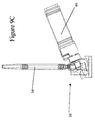
- the solution for reliably producing a circular corneal cut is to equip microkeratome 10 with an arcuate cutting blade, as seen at 54a in FIGS. 12A-12C.
- the cutting blade may include a substantially rectangular plate having one of its edges 80 sharpened for cutting. In a preferred embodiment, the plate has a smooth, continuous bend therein making the cutting edge arcuately shaped, as seen particularly in FIGS. 12C and 15B.
- the cutting blade preferably includes steel, and may comprise a stainless steel alloy.
- An opening 53a is provided in the plate of cutting blade 54a for engagement by projection 53a of blade holder 52a. The engagement of blade holder 52a and arcuate cutting blade 54a is shown in FIGS. 13A and 13B.
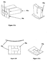
- FIGS. 14A and 14B are perspective and superior views of circular-shaped cutting disk 54p which was also experimented with, and was found to provide some utility, but was not found to be superior to the design of arcuate blade 54a.
- the use of cutting disk 54p requires a modification of the drive assembly (not shown) so that the disk is rotated, as indicated by the arrows in FIG. 14B, rather than being reciprocated across cutting head 16 like blades 54 and 54a.
- FIGS. 16 and 17 are posterior and anterior perspective views of cutting head 16a, blade holder 52a, and arcuate cutting blade 54a in accordance with the present invention.
- Support shaft 30 extends laterally through cutting head body 32a and terminates in support members 31, 33.
- Gear 62 is mounted about the central portion of support shaft 30 within cutting head body 32a, as seen particularly in FIG. 17.
- FIG. 18 illustrates an alternative vertical support assembly 18a which is connected to guide ring 12a and includes a pair of U-shaped members 20a, 22a extending upwardly from the guide ring.
- the U-shaped members are separated 180° apart from each other by lateral support arm 70, and are elevated above guide ring 12a by vertical support arm 68 that extends upwardly from guide ring 12.
- U-shaped members 20a, 22a may extend directly upwardly from the guide ring (not shown) 180° apart from each other.
- FIGS. 19A-19D vertical support assembly 18a supports cutting head 16a for rotation about horizontal A-A axis such that rotation of the cutting head about the horizontal axis moves cutting blade 54a along an arcuate cutting path into engagement with the cornea of the ocular globe, whereby the arcuate cutting edge of the cutting blade cuts a substantially rounded corneal disk.
- FIG. 19D is a perspective view shown from the reverse angle of the perspective view shown in FIG. 19C.
- cutting blade 54a is moved out of the page and to the left in the perspective of FIG. 19C, and left and into the page in the perspective of FIG. 19D.
- cutting blade 54a may also be used to produce a substantially oval-shaped corneal disk. This type of oval-shaped disk is also achievable with cutting blade 54 having the straight cutting edge, as described above, and may be selectively used to provide certain advantages in corneal resections.
- a nasal hinge cannot prevent movement of the corneal flap under the vertical reciprocating motion of the eyelid.
- a superior or upper hinge on the other hand, will keep the corneal flap in place under blinking action of the eyelid.
Landscapes
- Health & Medical Sciences (AREA)
- Ophthalmology & Optometry (AREA)
- Life Sciences & Earth Sciences (AREA)
- Animal Behavior & Ethology (AREA)
- Engineering & Computer Science (AREA)
- Biomedical Technology (AREA)
- Heart & Thoracic Surgery (AREA)
- Vascular Medicine (AREA)
- Nuclear Medicine, Radiotherapy & Molecular Imaging (AREA)
- Surgery (AREA)
- General Health & Medical Sciences (AREA)
- Public Health (AREA)
- Veterinary Medicine (AREA)
- Surgical Instruments (AREA)
- Waveguide Aerials (AREA)
- Radiation-Therapy Devices (AREA)
- Prostheses (AREA)
Claims (8)
- Microkératome destiné à la réalisation d'une kératotomie d'un globe oculaire comprenant un ensemble de guidage annulaire (12, 12a) prévu d'être positionné sur le globe oculaire, un moyen (14) pour fixer temporairement l'anneau de guidage (12, 12a) sur le globe oculaire, une tête de coupe (16, 16a) enfermant une lame de coupe (54, 54a) adapté pour la réalisation de résections cornéennes ainsi qu'un ensemble de support vertical (18,18a) relié audit anneau de guidage (12, 12a),
caractérisé en ce que ledit ensemble de support vertical (18, 18a) supporte ladite tête de coupe (16, 16a) pour tourner autour d'un axe horizontal de façon que la rotation de ladite tête de coupe (16, 16a) autour de l'axe horizontal fait déplacer la lame de coupe (54, 54a) le long d'un trajet de coupe arqué jusqu'à prendre dans la cornée du globe oculaire. - Microkératome selon la revendication 1 dans lequel ladite lame de coupe (54, 54a) présente une arête de coupe arquée, de manière que l'arête de coupe arquée de la lame de coupe (54, 54a) coupe une disque cornéenne sensiblement arrondie.
- Microkératome selon la revendication 1 ou 2 comprenant par ailleurs des moyens (44, 4.6, 48) pour tourner ladite tête de coupe (16, 16a) autour de l'axe horizontal afin de déplacer la lame de coupe (54, 54a) au moins partiellement à travers la cornée pour créer un volet cornéen pendant une kératotomie lamellaire.
- Microkératome selon la revendication 3 dans lequel lesdits moyens de rotation (44, 46, 48) comprennent des moyens (48) pour induire un mouvement oscillant dans la lame de coupe (54, 54a) de ladite tête de coupe (16, 16a) qui est transversal au trajet de coupe défini par la rotation de ladite tête de coupe (16, 16a) autour de l'axe horizontal.
- Microkératome selon la revendication 3 ou 4, comprenant par ailleurs des moyens d'arrêt pour limiter la portée à travers de laquelle la lame de coupe (54, 54a) est guidée par ladite tête de coupe (16, 16a) afin de définir une articulation cornéenne pendant une kératotomie lamellaire.
- Microkératome selon l'une des revendication précédentes, dans lequel ledit ensemble de support vertical (18, 18a) comprend une paire d'éléments (20, 20a, 22, 22a) s'étendant vers le haut depuis ledit anneau de guidage (12, 12a) avec un espacement de 180° l'un de l'autre, et dans lequel ladite tête de coupe (16, 16a) comprend un arbre de support (30) s'étendant latéralement à travers celle-ci, équipé d'éléments de support latéraux (31, 31a, 31b, 33, 33a, 33b) à chacune des extrémités de l'arbre de support (30) s'étendant depuis les côtés opposés de ladite tête de coupe (16, 16a) afin de prendre dans les éléments dudit ensemble de support (18, 18a) s'étendant vers le haut (20, 20a, 22, 22a).
- Microkératome selon l'une des revendication précédentes dans lequel ladite tête de coupe (16, 16a) comprend des portions supérieure et inférieure reliées l'une avec l'autre par l'intermédiaire d'une articulation permettant l'ouverture de ladite tête de coupe (16, 16a) pour donner accès à la lame de coupe (54, 54a).
- Microkératome selon l'une des revendication précédentes, dans lequel ladite tête de coupe (16, 16a) comprend une ouverture (36) donnant accès à l'arbre de support (30) et dans lequel les moyens de rotation (44, 46, 48) comprennent une boíte (40) apte à servir de lien à la tête de coupe (16, 16a) sur l'ouverture (36) prévue dans cette dernière, un arbre de sortie (46) étant prévu de façon rotative à l'intérieur de la boíte (40), et présentant une portion extérieure (48) s'étendant à partir de la boíte (40) pour passer à travers l'ouverture (36) prévue dans ladite tête de coupe (16, 16a) et s'engrener dans l'arbre de support (30) lorsque la boíte (40) est raccordée à ladite tête de coupe (16, 16a), ainsi que des moyens prévus à l'intérieur de la boíte (40) prévus prévus d'appliquer un couple de rotation sur l'arbre de sortie (46), l'application du couple de rotation réalisée à l'aide des moyens d'application de couple de rotation sur l'arbre de sortie (46) entraínant la rotation de ladite tête de coupe (16, 16a) et de la boíte (40) autour de l'arbre de sortie (30) à une vitesse réglée.
Priority Applications (1)
| Application Number | Priority Date | Filing Date | Title |
|---|---|---|---|
| DK00922122T DK1085840T3 (da) | 1999-04-12 | 2000-04-12 | Mikrokeratom til udövelse af hornhinderesektioner |
Applications Claiming Priority (7)
| Application Number | Priority Date | Filing Date | Title |
|---|---|---|---|
| US12885199P | 1999-04-12 | 1999-04-12 | |
| US128851P | 1999-04-12 | ||
| US375154 | 1999-08-16 | ||
| US09/375,154 US6296650B1 (en) | 1999-04-12 | 1999-08-16 | Microkeratome |
| US09/517,025 US6656196B1 (en) | 1999-04-12 | 2000-03-02 | Microkeratome cutting blade and method for performing corneal resections |
| US517025 | 2000-03-02 | ||
| PCT/US2000/009797 WO2000061015A1 (fr) | 1999-04-12 | 2000-04-12 | Microkeratome et procede d'execution de resections corneennes |
Publications (3)
| Publication Number | Publication Date |
|---|---|
| EP1085840A1 EP1085840A1 (fr) | 2001-03-28 |
| EP1085840A4 EP1085840A4 (fr) | 2003-03-19 |
| EP1085840B1 true EP1085840B1 (fr) | 2005-03-09 |
Family
ID=46203839
Family Applications (1)
| Application Number | Title | Priority Date | Filing Date |
|---|---|---|---|
| EP00922122A Expired - Lifetime EP1085840B1 (fr) | 1999-04-12 | 2000-04-12 | Microkeratome pour l'execution de resections corneennes |
Country Status (11)
| Country | Link |
|---|---|
| US (1) | US6656196B1 (fr) |
| EP (1) | EP1085840B1 (fr) |
| JP (1) | JP2003510107A (fr) |
| KR (1) | KR20010052809A (fr) |
| CN (1) | CN1204852C (fr) |
| AT (1) | ATE290340T1 (fr) |
| AU (1) | AU773681B2 (fr) |
| CA (1) | CA2335040C (fr) |
| DE (1) | DE60018517T2 (fr) |
| ES (1) | ES2240092T3 (fr) |
| WO (1) | WO2000061015A1 (fr) |
Families Citing this family (11)
| Publication number | Priority date | Publication date | Assignee | Title |
|---|---|---|---|---|
| ES2150863B1 (es) | 1998-08-03 | 2001-06-16 | Novosalud Sl | Microqueratomo para la diseccion de lamelas de tejido corneal. |
| DE20104148U1 (de) * | 2001-03-09 | 2002-04-18 | view-point technology AG, 63801 Kleinostheim | Klingenhalterung für ein medizinisches Gerät |
| US20040127921A1 (en) * | 2002-12-30 | 2004-07-01 | Powell Ian A. | Keyed microkeratome cutting blade assembly |
| JP2008503265A (ja) * | 2004-06-16 | 2008-02-07 | ティッシュー エンジニアリング リフラクション, インコーポレイティッド | 上皮剥離デバイス |
| US20060173470A1 (en) * | 2005-01-31 | 2006-08-03 | Oray B N | Surgical fastener buttress material |
| DE102005022708B4 (de) * | 2005-05-18 | 2009-01-08 | Taneri, Suphi, Dr. med. | Mikrokeratom-Schneidklinge |
| DE102005022709B4 (de) * | 2005-05-18 | 2008-06-12 | Taneri, Suphi, Dr. med. | Schneidklinge und Schneidkopf für ein Mikrokeratom |
| US20070138863A1 (en) * | 2005-11-01 | 2007-06-21 | Warren Clark | Modular Pedal Box Assembly |
| WO2014005689A2 (fr) | 2012-07-03 | 2014-01-09 | Kuka Laboratories Gmbh | Système d'instrument chirurgical, système de chaîne cinématique, en particulier robotisée, d'un instrument chirurgical et instrument chirurgical |
| CN103393478B (zh) * | 2013-08-19 | 2015-04-22 | 天津开发区合普工贸有限公司 | 一种快捷动物眼角膜切割装置 |
| CN111991140A (zh) * | 2020-09-10 | 2020-11-27 | 四川视佳生物科技有限公司 | 用于角膜移植手术的切割工具 |
Family Cites Families (17)
| Publication number | Priority date | Publication date | Assignee | Title |
|---|---|---|---|---|
| FR1366323A (fr) * | 1963-07-31 | 1964-07-10 | Trépan notamment pour chirurgie oculaire | |
| US4688570A (en) * | 1981-03-09 | 1987-08-25 | The Regents Of The University Of California | Ophthalmologic surgical instrument |
| DE3433581C2 (de) | 1984-09-13 | 1986-08-07 | Fa. Carl Zeiss, 7920 Heidenheim | Vorrichtung zur lamellierenden, refraktiven Hornhautchirurgie |
| DE3523015A1 (de) * | 1985-06-27 | 1987-01-02 | Patrik Dr Med Gruendler | Vorrichtung zur fixierung eines cornea-transplantats im menschlichen auge |
| DE68923797T2 (de) * | 1989-12-11 | 1995-12-07 | Haruo Takase | Skalpell. |
| US5133726A (en) | 1990-02-14 | 1992-07-28 | Ruiz Luis A | Automatic corneal shaper |
| US5507759A (en) * | 1994-01-14 | 1996-04-16 | Nordan; Lee T. | Variable resection keratoplasty method |
| US5496339A (en) | 1994-05-17 | 1996-03-05 | Koepnick; Russell G. | Universal automated keratectomy apparatus and method |
| US5586980A (en) | 1994-10-14 | 1996-12-24 | Kremer; Frederic B. | Microkeratome |
| US6007553A (en) * | 1996-02-07 | 1999-12-28 | Hellenkamp; Johann F. | Automatic surgical device control assembly for cutting a cornea |
| US6051009A (en) * | 1996-02-07 | 2000-04-18 | Hellenkamp; Johann F. | Automatic surgical device for cutting a cornea and a cutting blade assembly and control assembly |
| US5624456A (en) | 1996-02-07 | 1997-04-29 | Hellenkamp; Johann F. | Automatic surgical device for cutting a cornea |
| JP2002515788A (ja) * | 1996-07-19 | 2002-05-28 | ケラビジョン,インコーポレイテッド | 眼科装置およびその使用方法 |
| BR9714079A (pt) | 1996-12-23 | 2000-05-02 | Inst Barraquer De America | Microcerátomo |
| US6071293A (en) * | 1997-04-25 | 2000-06-06 | Krumeich; Joerg H. | Automatic microkeratome |
| US6030398A (en) * | 1997-05-30 | 2000-02-29 | Summit Technology, Inc. | Surgical microtomes |
| US6143010A (en) | 1997-07-18 | 2000-11-07 | Kera Vision Inc. | Corneal vacuum centering device |
-
2000
- 2000-03-02 US US09/517,025 patent/US6656196B1/en not_active Expired - Fee Related
- 2000-04-12 DE DE60018517T patent/DE60018517T2/de not_active Expired - Lifetime
- 2000-04-12 CA CA002335040A patent/CA2335040C/fr not_active Expired - Fee Related
- 2000-04-12 AU AU42357/00A patent/AU773681B2/en not_active Ceased
- 2000-04-12 WO PCT/US2000/009797 patent/WO2000061015A1/fr not_active Application Discontinuation
- 2000-04-12 JP JP2000610356A patent/JP2003510107A/ja active Pending
- 2000-04-12 EP EP00922122A patent/EP1085840B1/fr not_active Expired - Lifetime
- 2000-04-12 ES ES00922122T patent/ES2240092T3/es not_active Expired - Lifetime
- 2000-04-12 KR KR1020007014131A patent/KR20010052809A/ko not_active Application Discontinuation
- 2000-04-12 AT AT00922122T patent/ATE290340T1/de not_active IP Right Cessation
- 2000-04-12 CN CNB008010722A patent/CN1204852C/zh not_active Expired - Fee Related
Also Published As
| Publication number | Publication date |
|---|---|
| CA2335040C (fr) | 2005-10-18 |
| AU773681B2 (en) | 2004-06-03 |
| CN1313737A (zh) | 2001-09-19 |
| US6656196B1 (en) | 2003-12-02 |
| EP1085840A1 (fr) | 2001-03-28 |
| CA2335040A1 (fr) | 2000-10-19 |
| EP1085840A4 (fr) | 2003-03-19 |
| WO2000061015A1 (fr) | 2000-10-19 |
| DE60018517T2 (de) | 2006-04-13 |
| DE60018517D1 (de) | 2005-04-14 |
| WO2000061015A9 (fr) | 2002-05-02 |
| ES2240092T3 (es) | 2005-10-16 |
| ATE290340T1 (de) | 2005-03-15 |
| JP2003510107A (ja) | 2003-03-18 |
| KR20010052809A (ko) | 2001-06-25 |
| CN1204852C (zh) | 2005-06-08 |
| AU4235700A (en) | 2000-11-14 |
Similar Documents
| Publication | Publication Date | Title |
|---|---|---|
| EP0971659B1 (fr) | Microkeratome | |
| EP1626688B1 (fr) | Systeme de coupe de la cornee d'un oeil | |
| AU706115B2 (en) | Improved automatic surgical device for cutting a cornea | |
| US5658303A (en) | Universal automated keratectomy apparatus and method | |
| US9675495B2 (en) | Capsulotomy instrument | |
| EP1085840B1 (fr) | Microkeratome pour l'execution de resections corneennes | |
| US20050288696A1 (en) | Device for separating the epithelial layer from the surface of the cornea of an eye | |
| US6296650B1 (en) | Microkeratome | |
| EP1784148A2 (fr) | Dispositif de separation de la couche epitheliale de la surface de la cornee de l'oeil | |
| US20010053917A1 (en) | Non-plane cut microkeratome and method of performing non-plane keratotomy | |
| US20040002722A1 (en) | Ultrasonic microkeratome | |
| TW487570B (en) | Microkeratome and method for performing corneal resections | |
| US20070265650A1 (en) | Device for separating the epithelial layer from the surface of the cornea of an eye | |
| US20010018590A1 (en) | Microkeratome |
Legal Events
| Date | Code | Title | Description |
|---|---|---|---|
| PUAI | Public reference made under article 153(3) epc to a published international application that has entered the european phase |
Free format text: ORIGINAL CODE: 0009012 |
|
| 17P | Request for examination filed |
Effective date: 20010110 |
|
| AK | Designated contracting states |
Kind code of ref document: A1 Designated state(s): AT BE CH CY DE DK ES FI FR GB GR IE IT LI LU MC NL PT SE |
|
| RAP1 | Party data changed (applicant data changed or rights of an application transferred) |
Owner name: CARRIAZO, CESAR C. |
|
| A4 | Supplementary search report drawn up and despatched |
Effective date: 20030130 |
|
| RIC1 | Information provided on ipc code assigned before grant |
Ipc: 7A 61B 17/32 A Ipc: 7A 61F 9/013 B |
|
| 17Q | First examination report despatched |
Effective date: 20030821 |
|
| RTI1 | Title (correction) |
Free format text: MICROKERATOME FOR PERFORMING CORNEAL RESECTIONS |
|
| GRAP | Despatch of communication of intention to grant a patent |
Free format text: ORIGINAL CODE: EPIDOSNIGR1 |
|
| GRAS | Grant fee paid |
Free format text: ORIGINAL CODE: EPIDOSNIGR3 |
|
| GRAA | (expected) grant |
Free format text: ORIGINAL CODE: 0009210 |
|
| AK | Designated contracting states |
Kind code of ref document: B1 Designated state(s): AT BE CH CY DE DK ES FI FR GB GR IE IT LI LU MC NL PT SE |
|
| PG25 | Lapsed in a contracting state [announced via postgrant information from national office to epo] |
Ref country code: IT Free format text: LAPSE BECAUSE OF FAILURE TO SUBMIT A TRANSLATION OF THE DESCRIPTION OR TO PAY THE FEE WITHIN THE PRESCRIBED TIME-LIMIT;WARNING: LAPSES OF ITALIAN PATENTS WITH EFFECTIVE DATE BEFORE 2007 MAY HAVE OCCURRED AT ANY TIME BEFORE 2007. THE CORRECT EFFECTIVE DATE MAY BE DIFFERENT FROM THE ONE RECORDED. Effective date: 20050309 |
|
| REG | Reference to a national code |
Ref country code: GB Ref legal event code: FG4D |
|
| REG | Reference to a national code |
Ref country code: CH Ref legal event code: EP |
|
| RAP2 | Party data changed (patent owner data changed or rights of a patent transferred) |
Owner name: LOULOU CORPORATION N.V |
|
| RAP2 | Party data changed (patent owner data changed or rights of a patent transferred) |
Owner name: VISION RESEARCH B.V. |
|
| REG | Reference to a national code |
Ref country code: IE Ref legal event code: FG4D |
|
| PG25 | Lapsed in a contracting state [announced via postgrant information from national office to epo] |
Ref country code: IE Free format text: LAPSE BECAUSE OF NON-PAYMENT OF DUE FEES Effective date: 20050412 Ref country code: CY Free format text: LAPSE BECAUSE OF FAILURE TO SUBMIT A TRANSLATION OF THE DESCRIPTION OR TO PAY THE FEE WITHIN THE PRESCRIBED TIME-LIMIT Effective date: 20050412 Ref country code: LU Free format text: LAPSE BECAUSE OF NON-PAYMENT OF DUE FEES Effective date: 20050412 |
|
| REF | Corresponds to: |
Ref document number: 60018517 Country of ref document: DE Date of ref document: 20050414 Kind code of ref document: P |
|
| PG25 | Lapsed in a contracting state [announced via postgrant information from national office to epo] |
Ref country code: MC Free format text: LAPSE BECAUSE OF NON-PAYMENT OF DUE FEES Effective date: 20050430 |
|
| NLT2 | Nl: modifications (of names), taken from the european patent patent bulletin |
Owner name: LOULOU CORPORATION N.V Owner name: VISION RESEARCH B.V. |
|
| PG25 | Lapsed in a contracting state [announced via postgrant information from national office to epo] |
Ref country code: GR Free format text: LAPSE BECAUSE OF FAILURE TO SUBMIT A TRANSLATION OF THE DESCRIPTION OR TO PAY THE FEE WITHIN THE PRESCRIBED TIME-LIMIT Effective date: 20050609 Ref country code: GB Free format text: LAPSE BECAUSE OF NON-PAYMENT OF DUE FEES Effective date: 20050609 |
|
| REG | Reference to a national code |
Ref country code: DK Ref legal event code: T3 |
|
| REG | Reference to a national code |
Ref country code: SE Ref legal event code: TRGR |
|
| REG | Reference to a national code |
Ref country code: GB Ref legal event code: ERR Free format text: NOTIFICATION HAS NOW BEEN RECEIVED FROM THE EUROPEAN PATENT OFFICE THAT THE CORRECT NAME OF THE APPLICANT/PROPRIETOR IS: VISION RESEARCH B.V. THIS CORRECTION WAS PUBLISHED IN THE EUROPEAN PATENT BULLETIN 05/13 DATED 20050330 |
|
| PG25 | Lapsed in a contracting state [announced via postgrant information from national office to epo] |
Ref country code: PT Free format text: LAPSE BECAUSE OF FAILURE TO SUBMIT A TRANSLATION OF THE DESCRIPTION OR TO PAY THE FEE WITHIN THE PRESCRIBED TIME-LIMIT Effective date: 20050907 |
|
| REG | Reference to a national code |
Ref country code: CH Ref legal event code: NV Representative=s name: BREITER + PARTNER AG PATENT - UND MARKENBUERO |
|
| NLXE | Nl: other communications concerning ep-patents (part 3 heading xe) |
Free format text: PAT. BUL. 08/2005: CORR.: VISION RESEARCH B.V. |
|
| REG | Reference to a national code |
Ref country code: ES Ref legal event code: FG2A Ref document number: 2240092 Country of ref document: ES Kind code of ref document: T3 |
|
| PLBE | No opposition filed within time limit |
Free format text: ORIGINAL CODE: 0009261 |
|
| STAA | Information on the status of an ep patent application or granted ep patent |
Free format text: STATUS: NO OPPOSITION FILED WITHIN TIME LIMIT |
|
| 26N | No opposition filed |
Effective date: 20051212 |
|
| GBPC | Gb: european patent ceased through non-payment of renewal fee |
Effective date: 20050609 |
|
| ET | Fr: translation filed | ||
| REG | Reference to a national code |
Ref country code: CH Ref legal event code: PFA Owner name: VISION RESEARCH B.V. Free format text: VISION RESEARCH B.V.#PARNASSUSTOREN LOCATELLIKADE#1076 AZ AMSTERDAM (NL) -TRANSFER TO- VISION RESEARCH B.V.#PARNASSUSTOREN LOCATELLIKADE#1076 AZ AMSTERDAM (NL) |
|
| PGFP | Annual fee paid to national office [announced via postgrant information from national office to epo] |
Ref country code: NL Payment date: 20070417 Year of fee payment: 8 |
|
| PGFP | Annual fee paid to national office [announced via postgrant information from national office to epo] |
Ref country code: FI Payment date: 20070420 Year of fee payment: 8 |
|
| PGFP | Annual fee paid to national office [announced via postgrant information from national office to epo] |
Ref country code: AT Payment date: 20070423 Year of fee payment: 8 |
|
| PGFP | Annual fee paid to national office [announced via postgrant information from national office to epo] |
Ref country code: CH Payment date: 20070424 Year of fee payment: 8 |
|
| PGFP | Annual fee paid to national office [announced via postgrant information from national office to epo] |
Ref country code: DK Payment date: 20070425 Year of fee payment: 8 Ref country code: ES Payment date: 20070425 Year of fee payment: 8 |
|
| PGFP | Annual fee paid to national office [announced via postgrant information from national office to epo] |
Ref country code: BE Payment date: 20070419 Year of fee payment: 8 |
|
| PGFP | Annual fee paid to national office [announced via postgrant information from national office to epo] |
Ref country code: FR Payment date: 20070418 Year of fee payment: 8 |
|
| BERE | Be: lapsed |
Owner name: *VISION RESEARCH B.V. Effective date: 20080430 |
|
| REG | Reference to a national code |
Ref country code: CH Ref legal event code: PL |
|
| REG | Reference to a national code |
Ref country code: DK Ref legal event code: EBP |
|
| NLV4 | Nl: lapsed or anulled due to non-payment of the annual fee |
Effective date: 20081101 |
|
| PG25 | Lapsed in a contracting state [announced via postgrant information from national office to epo] |
Ref country code: NL Free format text: LAPSE BECAUSE OF NON-PAYMENT OF DUE FEES Effective date: 20081101 Ref country code: LI Free format text: LAPSE BECAUSE OF NON-PAYMENT OF DUE FEES Effective date: 20080430 Ref country code: CH Free format text: LAPSE BECAUSE OF NON-PAYMENT OF DUE FEES Effective date: 20080430 |
|
| REG | Reference to a national code |
Ref country code: FR Ref legal event code: ST Effective date: 20081231 |
|
| PG25 | Lapsed in a contracting state [announced via postgrant information from national office to epo] |
Ref country code: AT Free format text: LAPSE BECAUSE OF NON-PAYMENT OF DUE FEES Effective date: 20080412 Ref country code: FI Free format text: LAPSE BECAUSE OF NON-PAYMENT OF DUE FEES Effective date: 20080412 |
|
| PG25 | Lapsed in a contracting state [announced via postgrant information from national office to epo] |
Ref country code: BE Free format text: LAPSE BECAUSE OF NON-PAYMENT OF DUE FEES Effective date: 20080430 |
|
| PG25 | Lapsed in a contracting state [announced via postgrant information from national office to epo] |
Ref country code: DK Free format text: LAPSE BECAUSE OF NON-PAYMENT OF DUE FEES Effective date: 20080430 Ref country code: FR Free format text: LAPSE BECAUSE OF NON-PAYMENT OF DUE FEES Effective date: 20080430 |
|
| REG | Reference to a national code |
Ref country code: ES Ref legal event code: FD2A Effective date: 20080414 |
|
| PG25 | Lapsed in a contracting state [announced via postgrant information from national office to epo] |
Ref country code: ES Free format text: LAPSE BECAUSE OF NON-PAYMENT OF DUE FEES Effective date: 20080414 |
|
| PGFP | Annual fee paid to national office [announced via postgrant information from national office to epo] |
Ref country code: SE Payment date: 20090427 Year of fee payment: 10 |
|
| EUG | Se: european patent has lapsed | ||
| PGFP | Annual fee paid to national office [announced via postgrant information from national office to epo] |
Ref country code: DE Payment date: 20120430 Year of fee payment: 13 |
|
| PG25 | Lapsed in a contracting state [announced via postgrant information from national office to epo] |
Ref country code: SE Free format text: LAPSE BECAUSE OF NON-PAYMENT OF DUE FEES Effective date: 20100413 |
|
| PG25 | Lapsed in a contracting state [announced via postgrant information from national office to epo] |
Ref country code: DE Free format text: LAPSE BECAUSE OF NON-PAYMENT OF DUE FEES Effective date: 20131101 |
|
| REG | Reference to a national code |
Ref country code: DE Ref legal event code: R119 Ref document number: 60018517 Country of ref document: DE Effective date: 20131101 |