EP1085652A2 - Frequenzumsetzer und Hochfrequenztuner - Google Patents
Frequenzumsetzer und Hochfrequenztuner Download PDFInfo
- Publication number
- EP1085652A2 EP1085652A2 EP00307801A EP00307801A EP1085652A2 EP 1085652 A2 EP1085652 A2 EP 1085652A2 EP 00307801 A EP00307801 A EP 00307801A EP 00307801 A EP00307801 A EP 00307801A EP 1085652 A2 EP1085652 A2 EP 1085652A2
- Authority
- EP
- European Patent Office
- Prior art keywords
- frequency
- tuner
- mixer
- converter
- oscillator
- Prior art date
- Legal status (The legal status is an assumption and is not a legal conclusion. Google has not performed a legal analysis and makes no representation as to the accuracy of the status listed.)
- Withdrawn
Links
Images


Classifications
-
- H—ELECTRICITY
- H03—ELECTRONIC CIRCUITRY
- H03D—DEMODULATION OR TRANSFERENCE OF MODULATION FROM ONE CARRIER TO ANOTHER
- H03D7/00—Transference of modulation from one carrier to another, e.g. frequency-changing
- H03D7/18—Modifications of frequency-changers for eliminating image frequencies
Definitions
- the present invention relates to a single conversion frequency converter for use in a radio frequency tuner.
- the present invention also relates to a radio frequency tuner comprising such a frequency converter.
- Such tuners have many applications but a particular application is to digital cable tuners for receiving from a cable distribution system radio frequency signals modulated with digital information.
- the basic purpose of a frequency converter of a radio frequency tuner is to amplify a radio frequency signal and to convert its frequency to a fixed intermediate frequency for filtering and demodulation.
- Such tuners have the following performance requirements:
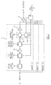
- FIG. 1 of the accompanying drawings illustrates part of a known type of single conversion tuner.
- the tuner comprises a frequency converter 1 whose output is connected to an intermediate frequency (IF) amplifier 2 which provides an IF output.
- the frequency converter 1 is controlled by a phase-locked loop (PLL) synthesiser 3 which is part of the frequency converter but which is shown separately in Figure 1.
- PLL phase-locked loop
- a frequency converter can operate over a frequency range which is typically limited to about one octave.
- the whole frequency range has to be split into several (typically three) bands.
- the frequency converter 1 is then embodied as several substantially identical channels (three shown in Figure 1) cooperating with a common synthesiser 3.
- the channel for band 1 is shown in Figure 1, the other channels being substantially identical.
- the channel comprises a band limit filter 4 whose input is connected to the RF input of the tuner and whose output is connected via a tracking local oscillator reject filter 5, a buffer stage 6, and an image reject filter 7 to a mixer oscillator 8 comprising a mixer 9 and a local oscillator 10.
- the output of the mixer/oscillator 8 is connected via another buffer stage 11 to the amplifier 2.
- the filters 5 and 7 and the local oscillator 10 are connected to the synthesiser 3.
- the synthesiser 3 controls the frequency of the local oscillator 10, which forms part of a phase-locked loop including the synthesiser 3, and controls the tracking of the filters 5 and 7 so that the local oscillator reject filter 5 tracks the frequency of the local oscillator 10 and the image reject filter 7 tracks the image channel corresponding to the local oscillator frequency.
- the single conversion tuner shown in Figure 1 requires the filters 4 and 7 to filter out or attenuate all undesired channels so that the single desired channel is supplied to the mixer 9 where it is down-converted to the intermediate frequency i.e. the intermediate frequency is below the frequency of the received channel.
- the filters 4 and 7 suppress undesired channels so as to minimise cross modulation and intermodulation.
- the image reject filter 7 suppresses the image channel and the local oscillator reject filter 5 suppresses leakage of the local oscillator signal to the RF input.
- the filters 5 and 7 have to be tracking filters, they cannot achieve the selectivity performance of fixed filters. As a result, cross modulation and intermodulation performance of the tuner suffers. Similarly, differential group delay and gain ripple performance is worse than for fixed filters.
- each local oscillator 10 has to tune over a wide range and must have a relatively small frequency step size, "close-in" phase noise performance is relatively poor.
- mixer oscillator 8 and the synthesiser 3 can be formed in a single integrated circuit in a cost-effective manner, further "up-integration" is not at present cost-effective.
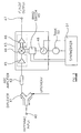
- FIG. 2 of the accompanying drawings illustrates another known type of tuner of the double conversion type.
- the tuner comprises a band limit filter 20 connected to the RF input.
- the filtered signals are supplied to a variable gain amplifier 21 which receives an automatic gain control (AGC) signal for controlling its gain so as to reduce the range of signal levels at its output.
- AGC automatic gain control
- the output of the amplifier 21 is supplied to the first frequency converter in the form of an "up" mixer/oscillator 22 comprising a mixer 23 and a local oscillator 24 controlled by an "up" phase-locked loop synthesiser 25.
- the up mixer/oscillator 22 converts the whole of the signal band limited by the filter 20 to a fixed intermediate frequency which is higher than the received band.
- the output of the mixer/oscillator 22 is connected via a fixed image reject filter 26 to a second frequency converter in the form of a down mixer/oscillator 27 comprising a mixer 28 and a local oscillator 29 controlled by a "down" phase-locked loop synthesiser 30.
- the mixer/oscillator 27 converts the desired channel to a lower intermediate frequency which is typically the same intermediate frequency as for the single conversion tuner shown in Figure 1.
- the output of the mixer/oscillator 27 is connected via an amplifier 31 to supply an IF output.
- the first converter 22 is required to have high signal handling capabilities so as to minimise cross modulation and intermodulation.
- the up-converter has a wide tuning range and hence potentially a poor phase noise performance. Compensation for this is achieved by applying a coarse step size low noise phase-locked loop which controls the "close-in" phase noise.
- the down-converter 27 has a very narrow tuning range and so can have a good phase noise performance. Small fine tuning steps may therefore be used for accurate tuning alignment.
- the up-converter 22 must be carefully designed so as to provide adequate cross modulation and intermodulation performance.
- the double conversion tuner has a poorer selectivity performance of desired weak channels in the presence of strong undesired channels.
- Double conversion tuners of the type shown in Figure 2 comprise two oscillators 24 and 29 which are always running and which may interfere which each other or generate spurious mixing products by cross mixing.
- both the frequency changers have to operate at the maximum power dissipation allowable in a given package. This makes it difficult to combine an up converter and a down converter in a single package because of the power constraints.
- a double conversion tuner comprises two synthesisers as welt as the up- and down-converters. This results in a large area of circuitry which is difficult to integrate in a cost-effective manner, even if the problems of interference and power dissipation using a single package can be overcome economically.
- W0/9708843 discloses a complex arrangement in the form of a general purpose module which is capable of receiving signals over a very wide radio frequency range. In one of its modes of operation this arrangement appears to perform a single conversion with a mixer receiving a local oscillator signal via switchable dividers with the options of a divert connection.
- GB 2 188 804 discloses a frequency synthesiser in which the mixer receives an oscillator signal from the output of a multiplexer.
- the inputs of the multiplexer are connected such that the mixer receives the oscillator signal: directly from the local oscillator; via a divide-by-two circuit; via a divide-by-four circuit and the divide-by-two circuit connected in cascade.
- GB 1 420 271 discloses a frequency changer having a crystal-controlled local oscillator whose outputs are supplied to a mixer via integral dividers providing division ratios of 20, 15, 12 and 10.
- a single conversion frequency converter comprising a mixer and a local oscillator, the local oscillator comprising a variable frequency oscillator and a variable divider for receiving from the variable frequency oscillator a variable frequency signal and for supplying to the mixer a local oscillator signal whose frequency is equal to the frequency of the variable frequency signal divided by any selected one of a plurality of integers, each of which is greater than one, characterised in that the mixer is an image reject mixer.
- the variable divider may comprise a plurality of divide-by-two stages and a multiplexer whose inputs are connected to respective outputs of the divide-by-two stages.
- the variable frequency oscillator may be tuneable over a frequency range which is greater than or equal to one octave.
- variable frequency oscillator may comprise part of a frequency synthesiser.
- the mixer may be connected to a signal source via a non-frequency-selective signal path.
- the input of the mixer may be connected to a signal input via an automatic gain control circuit.
- the input of the mixer may be connected to a signal input via a plurality of input stages.
- the converter may comprise a single chip integrated circuit.
- a radio frequency tuner comprising a converter according to the first aspect of the invention.
- the tuner may comprise a digital tuner.
- the tuner may comprise a cable tuner.
- the tuner may comprise a single chip integrated circuit.
- the local oscillator frequency is outside the received signal band so that a local oscillator reject filter for preventing re-radiation from the input is unnecessary. Further, leakage of the local oscillator signal to the input of the mixer can be held to a sufficiently low level to avoid any significant interference.
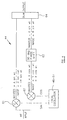
- FIG. 3 shows a frequency converter and part of a radio frequency tuner.
- the tuner is of the type for use with a cable distribution network having a common antennae input 40 and connected to the tuner by a diplexer 41.
- the tuner comprises an automatic gain control amplifier 42 whose input is connected to the diplexer 41 and whose output is connected to a single conversion frequency converter 43.
- the frequency converter 43 comprises a mixer 44 of the image reject type which receives input signals via a buffer stage 45 from the AGC amplifier 42 and supplies via a further buffer stage 46 standard intermediate frequency (IF) signals or near zero intermediate frequency (NZIF) signals to an output 47.
- IF intermediate frequency
- NZIF near zero intermediate frequency
- the frequency converter 43 also comprises a local oscillator which supplies in-phase (I) and quadrature (Q) local oscillator signals to the mixer 44.
- the local oscillator comprises a variable frequency oscillator 48 whose output is connected to a band-switching arrangement 49.
- the oscillator 48 has a tank circuit 50 which determines the frequency of oscillation and which is controlled by a synthesiser 51 of the phase-locked loop type.
- the synthesiser 51 also controls band switching by the arrangement 49.
- the image reject mixer comprises first and second mixing circuits 61 and 62 which receive the RF input signal and which receive in-phase (SIN) and quadrature (COS) signals from the local oscillator.
- the wanted and image signals from one of the mixers 62 are supplied to a 90° phase shifting circuit 63 which converts the wanted signal to A.sin (wt) and the image signal to B.sin (wt) .
- the outputs of the mixing circuit 61 and the phase shifter 63 are supplied to a summing circuit 64 in which the wanted signals add together whereas the image signals cancel each other out.
- Figure 5 illustrates diagrammatically the variable frequency oscillator 48 and the band-switching arrangement 49.
- the arrangement 49 comprises four cascade-connected divide-by-two circuits 70 to 73 whose outputs are connected to a multiplexer 74.
- the multiplexer 74 receives a band select signal from the synthesiser 51 which selects which of the outputs of the divide-by-two circuits 70 to 73 is connected to the output of the multiplexer 74 and hence to the mixer 44.
- the frequencies shown in Figure 5 are typical of those used, for example, to select channels from a cable distribution system of the type illustrated diagrammatically in Figure 3.
- the oscillator 48 produces output signals which are tuneable over a range of slightly more than one octave, in this case from 0.96 to 2.08GHz.
- the multiplexer 74 thus selects from frequency bands of 0.48-1.04GHz, 0.24-0.52GHz, 120-260MHz and 60-130MHz. When used with an intermediate frequency of, for example, 36 MHz in the case of UK applications, this gives a tuning range of 24 to 920 MHz, which more than adequately covers the broadcast range.
- the whole of the circuitry shown in Figure 3 may be implemented in the form of a single chip integrated circuit.
- the output 47 is connected to other devices, such as an IF filter/amplifier arrangement and a quadrature amplitude modulation decoder and such devices may also be implemented on the same single chip integrated circuit to provide a single chip digital front end interface module.
Landscapes
- Engineering & Computer Science (AREA)
- Power Engineering (AREA)
- Superheterodyne Receivers (AREA)
Applications Claiming Priority (2)
| Application Number | Priority Date | Filing Date | Title |
|---|---|---|---|
| GB9921813 | 1999-09-16 | ||
| GBGB9921813.3A GB9921813D0 (en) | 1999-09-16 | 1999-09-16 | Frequency converter and radio frequency tuner |
Publications (2)
| Publication Number | Publication Date |
|---|---|
| EP1085652A2 true EP1085652A2 (de) | 2001-03-21 |
| EP1085652A3 EP1085652A3 (de) | 2003-10-01 |
Family
ID=10860968
Family Applications (1)
| Application Number | Title | Priority Date | Filing Date |
|---|---|---|---|
| EP00307801A Withdrawn EP1085652A3 (de) | 1999-09-16 | 2000-09-08 | Frequenzumsetzer und Hochfrequenztuner |
Country Status (4)
| Country | Link |
|---|---|
| US (1) | US6901248B1 (de) |
| EP (1) | EP1085652A3 (de) |
| JP (1) | JP2001128079A (de) |
| GB (1) | GB9921813D0 (de) |
Cited By (2)
| Publication number | Priority date | Publication date | Assignee | Title |
|---|---|---|---|---|
| US6973297B1 (en) | 1999-09-01 | 2005-12-06 | Sirific Wireless Corporation | Method and apparatus for down-conversion of radio frequency (RF) signals with reduced local oscillator leakage |
| US10649013B2 (en) * | 2015-02-27 | 2020-05-12 | Tokyo Metropolitan Industrial Technology Research Institute | Frequency converter, measuring system, and measuring method |
Families Citing this family (9)
| Publication number | Priority date | Publication date | Assignee | Title |
|---|---|---|---|---|
| EP1215820A3 (de) * | 2000-12-05 | 2004-04-14 | Zarlink Semiconductor Limited | Hochfrequenztuner |
| US6675003B1 (en) * | 2000-12-07 | 2004-01-06 | Sirf Technology, Inc. | L1/L2 GPS receiver |
| GB2398943B (en) * | 2003-02-28 | 2005-08-31 | Zarlink Semiconductor Ltd | Tuner |
| JP2008510407A (ja) * | 2004-06-08 | 2008-04-03 | コーニンクレッカ フィリップス エレクトロニクス エヌ ヴィ | 周波数可変装置 |
| US8275338B2 (en) * | 2009-07-10 | 2012-09-25 | Theta S.A. | Passive high frequency image reject mixer |
| US8331896B2 (en) * | 2009-07-10 | 2012-12-11 | Theta S.A. | Method of operation of a passive high-frequency image reject mixer |
| US8862088B2 (en) * | 2009-09-22 | 2014-10-14 | Nokia Corporation | Adjustable circuit architecture |
| EP2388921B1 (de) * | 2010-05-21 | 2013-07-17 | Nxp B.V. | Integrierte Schaltungen mit Frequenzerzeugungsschaltungen |
| US8818317B2 (en) | 2010-06-29 | 2014-08-26 | Nec Corporation | Frequency converter and receiver that uses the frequency converter |
Citations (3)
| Publication number | Priority date | Publication date | Assignee | Title |
|---|---|---|---|---|
| US3529260A (en) * | 1968-05-31 | 1970-09-15 | Gen Radio Co | Oscillator with frequency dividers for providing tunable sinusoidal outputs |
| US5826180A (en) * | 1994-08-08 | 1998-10-20 | Nice Systems Ltd. | Near homodyne radio frequency receiver |
| US5852772A (en) * | 1997-02-25 | 1998-12-22 | Ericsson Inc. | Receiver IF system with active filters |
Family Cites Families (14)
| Publication number | Priority date | Publication date | Assignee | Title |
|---|---|---|---|---|
| JPS5113279A (de) * | 1974-07-11 | 1976-02-02 | Suwa Seikosha Kk | |
| US3959737A (en) * | 1974-11-18 | 1976-05-25 | Engelmann Microwave Co. | Frequency synthesizer having fractional frequency divider in phase-locked loop |
| US4169385A (en) * | 1978-02-21 | 1979-10-02 | Picker Corporation | Frequency synthesizer apparatus and method in ultrasonic imaging |
| US4422052A (en) * | 1981-05-29 | 1983-12-20 | Rca Corporation | Delay circuit employing active bandpass filter |
| US4792987A (en) * | 1985-01-09 | 1988-12-20 | Starke Electronics, Inc. | Antenna coupling amplifier and converter system |
| US5060297A (en) * | 1988-04-04 | 1991-10-22 | Ma John Y | TVRO receiver system with tracking filter for rejection of image frequencies |
| US6014386A (en) * | 1989-10-30 | 2000-01-11 | Videocom, Inc. | System and method for high speed communication of video, voice and error-free data over in-wall wiring |
| US5192999A (en) * | 1991-04-25 | 1993-03-09 | Compuadd Corporation | Multipurpose computerized television |
| WO1994029948A1 (en) * | 1993-06-04 | 1994-12-22 | Rca Thomson Licensing Corporation | Direct conversion tuner |
| GB2311194B (en) * | 1996-03-12 | 2000-05-31 | Nokia Mobile Phones Ltd | Transmitting and receiving radio signals |
| JPH10256932A (ja) * | 1997-03-10 | 1998-09-25 | Alps Electric Co Ltd | アナログ・ディジタル放送共用受信チューナ |
| US6163684A (en) * | 1997-08-01 | 2000-12-19 | Microtune, Inc. | Broadband frequency synthesizer |
| DE19819038C2 (de) * | 1998-04-28 | 2002-01-03 | Rohde & Schwarz | Frequenzumsetzeranordnung für Hochfrequenzempfänger oder Hochfrequenzgeneratoren |
| US6169569B1 (en) * | 1998-05-22 | 2001-01-02 | Temic Telefumken | Cable modem tuner |
-
1999
- 1999-09-16 GB GBGB9921813.3A patent/GB9921813D0/en not_active Ceased
-
2000
- 2000-09-08 EP EP00307801A patent/EP1085652A3/de not_active Withdrawn
- 2000-09-11 US US09/658,745 patent/US6901248B1/en not_active Expired - Lifetime
- 2000-09-14 JP JP2000279588A patent/JP2001128079A/ja active Pending
Patent Citations (3)
| Publication number | Priority date | Publication date | Assignee | Title |
|---|---|---|---|---|
| US3529260A (en) * | 1968-05-31 | 1970-09-15 | Gen Radio Co | Oscillator with frequency dividers for providing tunable sinusoidal outputs |
| US5826180A (en) * | 1994-08-08 | 1998-10-20 | Nice Systems Ltd. | Near homodyne radio frequency receiver |
| US5852772A (en) * | 1997-02-25 | 1998-12-22 | Ericsson Inc. | Receiver IF system with active filters |
Cited By (4)
| Publication number | Priority date | Publication date | Assignee | Title |
|---|---|---|---|---|
| US6973297B1 (en) | 1999-09-01 | 2005-12-06 | Sirific Wireless Corporation | Method and apparatus for down-conversion of radio frequency (RF) signals with reduced local oscillator leakage |
| US7016662B1 (en) | 1999-09-01 | 2006-03-21 | Sirific Wireless Corporation | Method and apparatus for up-conversion of radio frequency (RF) signals |
| US7046980B1 (en) | 1999-09-01 | 2006-05-16 | Sirific Wireless Corporation | Method and apparatus for up-and down-conversion of radio frequency (RF) signals |
| US10649013B2 (en) * | 2015-02-27 | 2020-05-12 | Tokyo Metropolitan Industrial Technology Research Institute | Frequency converter, measuring system, and measuring method |
Also Published As
| Publication number | Publication date |
|---|---|
| US6901248B1 (en) | 2005-05-31 |
| GB9921813D0 (en) | 1999-11-17 |
| EP1085652A3 (de) | 2003-10-01 |
| JP2001128079A (ja) | 2001-05-11 |
Similar Documents
| Publication | Publication Date | Title |
|---|---|---|
| US6766178B1 (en) | RF architecture for cellular multi-band telephones | |
| US7266352B2 (en) | Multiple band RF transmitters and receivers having independently variable RF and IF local oscillators and independent high-side and low-side RF local oscillators | |
| US7003274B1 (en) | Frequency synthesizer and synthesis method for generating a multiband local oscillator signal | |
| US5966646A (en) | Dual-band radio receiver | |
| US7447491B2 (en) | Multi-tuner integrated circuit architecture utilizing frequency isolated local oscillators and associated method | |
| US6085075A (en) | Communication system, a communication device and a frequency synthesizer | |
| KR20030019565A (ko) | 집적된 튜너 회로 | |
| EP1151530A1 (de) | Sender-empfänger | |
| SE507527C2 (sv) | Flerbandsmottagare som genererar en mellanfrekvens som är gemensam för de olika frekvensbanden, och förfarande för densamma | |
| EP1524775A1 (de) | Radiofrequenzempfänger und Halbleiterschaltung zur Verwendung in dem Empfänger | |
| US6785518B2 (en) | Transmitter and receiver circuit for radio frequency signals | |
| US7509104B2 (en) | Method and apparatus for tuning radio frequency | |
| US6901248B1 (en) | Frequency converter and radio frequency tuner | |
| US6370368B1 (en) | Global tuner | |
| US6369666B1 (en) | Modulator circuit configuration | |
| US6628960B1 (en) | Multi-mode radio receiver | |
| US6934523B2 (en) | Tuner | |
| US6895063B1 (en) | Frequency changer and digital tuner | |
| KR100193836B1 (ko) | 감소된 위상동기루프를 가지는 디지털 무선통신시스템 및 그 동기화 방법 | |
| EP1489753B1 (de) | Hochfrequenz-Signalempfänger | |
| US5630214A (en) | Wide-band receiving apparatus with local oscillating circuit | |
| US7280163B2 (en) | Direct conversion tuner capable of receiving digital television signals in UHF band and VHF band | |
| US6993356B2 (en) | Frequency generating system for a mobile radio dual-band transceiver | |
| GB2392566A (en) | A tuner in which one band is up-converted and this or a second band is selected for direct conversion to baseband | |
| US5999572A (en) | Digital broadcasting receiver tuner |
Legal Events
| Date | Code | Title | Description |
|---|---|---|---|
| PUAI | Public reference made under article 153(3) epc to a published international application that has entered the european phase |
Free format text: ORIGINAL CODE: 0009012 |
|
| AK | Designated contracting states |
Kind code of ref document: A2 Designated state(s): AT BE CH CY DE DK ES FI FR GB GR IE IT LI LU MC NL PT SE |
|
| AX | Request for extension of the european patent |
Free format text: AL;LT;LV;MK;RO;SI |
|
| RAP1 | Party data changed (applicant data changed or rights of an application transferred) |
Owner name: ZARLINK SEMICONDUCTOR LIMITED |
|
| PUAL | Search report despatched |
Free format text: ORIGINAL CODE: 0009013 |
|
| AK | Designated contracting states |
Kind code of ref document: A3 Designated state(s): AT BE CH CY DE DK ES FI FR GB GR IE IT LI LU MC NL PT SE |
|
| AX | Request for extension of the european patent |
Extension state: AL LT LV MK RO SI |
|
| 17P | Request for examination filed |
Effective date: 20031118 |
|
| 17Q | First examination report despatched |
Effective date: 20040129 |
|
| AKX | Designation fees paid |
Designated state(s): DE |
|
| RBV | Designated contracting states (corrected) |
Designated state(s): GB |
|
| REG | Reference to a national code |
Ref country code: DE Ref legal event code: 8566 |
|
| STAA | Information on the status of an ep patent application or granted ep patent |
Free format text: STATUS: THE APPLICATION IS DEEMED TO BE WITHDRAWN |
|
| 18D | Application deemed to be withdrawn |
Effective date: 20060607 |