EP1085637A2 - Verfahren zur Kompensation von asymmetrischen Lasten in Mehrphasensystemen - Google Patents
Verfahren zur Kompensation von asymmetrischen Lasten in Mehrphasensystemen Download PDFInfo
- Publication number
- EP1085637A2 EP1085637A2 EP00810836A EP00810836A EP1085637A2 EP 1085637 A2 EP1085637 A2 EP 1085637A2 EP 00810836 A EP00810836 A EP 00810836A EP 00810836 A EP00810836 A EP 00810836A EP 1085637 A2 EP1085637 A2 EP 1085637A2
- Authority
- EP
- European Patent Office
- Prior art keywords
- compensation
- phase
- unit
- energy storage
- storage unit
- Prior art date
- Legal status (The legal status is an assumption and is not a legal conclusion. Google has not performed a legal analysis and makes no representation as to the accuracy of the status listed.)
- Granted
Links
Images

Classifications
-
- H—ELECTRICITY
- H02—GENERATION; CONVERSION OR DISTRIBUTION OF ELECTRIC POWER
- H02J—ELECTRIC POWER NETWORKS; CIRCUIT ARRANGEMENTS OR SYSTEMS FOR SUPPLYING OR DISTRIBUTING ELECTRIC POWER; SYSTEMS FOR STORING ELECTRIC ENERGY
- H02J3/00—Circuit arrangements for AC mains or AC distribution networks
- H02J3/26—Arrangements for eliminating or reducing asymmetry in polyphase networks
-
- Y—GENERAL TAGGING OF NEW TECHNOLOGICAL DEVELOPMENTS; GENERAL TAGGING OF CROSS-SECTIONAL TECHNOLOGIES SPANNING OVER SEVERAL SECTIONS OF THE IPC; TECHNICAL SUBJECTS COVERED BY FORMER USPC CROSS-REFERENCE ART COLLECTIONS [XRACs] AND DIGESTS
- Y02—TECHNOLOGIES OR APPLICATIONS FOR MITIGATION OR ADAPTATION AGAINST CLIMATE CHANGE
- Y02E—REDUCTION OF GREENHOUSE GAS [GHG] EMISSIONS, RELATED TO ENERGY GENERATION, TRANSMISSION OR DISTRIBUTION
- Y02E40/00—Technologies for an efficient electrical power generation, transmission or distribution
- Y02E40/50—Arrangements for eliminating or reducing asymmetry in polyphase networks
Definitions
- the present invention relates to a method according to the Preamble of claim 1 and a device to carry out the procedure.
- the supply of electrical energy takes place mainly and preferably via symmetrical ones Three-phase systems.
- Three-phase systems As a result of unequal loads between the individual phases become such three-phase systems asymmetrical, which also means that Energy loss or damage to electrical machines arise that are connected to the three-phase system.
- Asymmetric three-phase systems do not stand out only characterized by asymmetrical currents and phases, but especially through asymmetrical voltages, namely due to the different voltage drops in the individual branches.
- the asymmetrical voltages mentioned affect those associated with the three-phase systems electrical machines in a negative way.
- the degree of asymmetry is initially increased Energy losses, then with a reduced lifespan and ultimately to expect a machine failure.
- international standards and Recommendations in which the maximum allowable degree to asymmetry of a three-phase system (Engineering Recommendation, IEC - The Electrical Council, London, June 1975, p. 16).
- An asymmetry in a three-phase system can for example, through a single-phase induction furnace a single-phase train system that connects directly to the three-phase system is switched on, or by an arc melting furnace arise, which is basically a three-phase load represents an asymmetry in the short term can occur if one or two arcs go out.
- circuit breakers - like for example thyristors - can be the power factor be corrected as desired, i.e. Three-phase systems could can be balanced even with widely varying loads.
- a Circuit developed on this principle is in the above article by Gyugyi et. al. shown and explained (page 1942, right column, Fig. 14).
- the present invention is therefore based on the object based on specifying a method mentioned above Does not have disadvantages.
- the invention has the following advantages: By the in the Compensation unit generated any compensation currents Can have phases and any amplitudes achieved according to the invention that the performance Interpretation can be significantly reduced to the same Achieve degree of compensation, as it is known by the Compensation circuit from Steinmetz is possible.
- the method according to the invention then works in particular optimal if the amplitudes of the compensation currents are the same are big. So that are the branches of Compensation circuit utilized evenly.
- the method according to the invention is also distinguished characterized in that active power between at least two Phases is exchanged, namely over a Intermediate energy storage, preferably as a capacitor is realized.
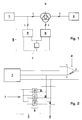
- Fig. 1 shows a schematic representation Arrangement according to the invention for compensating a asymmetrical load in a three-phase system, with 1 a supply part - for example a generator - and with 2 the asymmetrical load are designated.
- Fig. 1 are connections between the power supplies with 3 marked, as far as these are the three Lines of the three-phase system.
- Compensator unit 5 Between the supply part 1 and the load 2 is one Three-phase transformer unit 4 is provided, via one Compensator unit 5 to the transmission link between Supply part 1 and load 2 is coupled.
- the Compensator unit 5 in turn consists of one Switch unit 6 and an energy storage unit 7, wherein the switching unit 6 on the input side with the three-phase transformer unit 4 and on the output side with the Energy storage unit 7 is connected.
- FIG. 1 A further embodiment is shown in broken lines in FIG. 1 the arrangement according to the invention. So is with this in addition to the embodiment just described a charging unit 8 is provided, which is parallel on the input side to the energy storage unit 7 and in turn on the output side to the transmission link between supply part 1 and Load 2 is connected.
- Fig. 2 shows a specific embodiment of the 1 arrangement according to the invention without a loading unit 8.
- the compensator unit 5 is via a three-phase transformer unit 4 in a delta connection to the three Phases R, S and T of the transmission path between Supply part 1 and load 2 connected.
- On the Secondary sides of the three-phase transformer unit 4 is each a power switching element S1 or S2 or S3 is provided, the outputs of which are used as an energy buffer acting capacitor 7 are connected.
- the power switching elements S1 to S3 come, for example GTOs (gate turn-off thyristors) or IGBTs (insulated gate bipolar transistors) for use.
- GTOs gate turn-off thyristors
- IGBTs insulated gate bipolar transistors
- Fig. 2 the load 2 is reduced by a Delta connection shown, in which the asymmetry in there is an impedance between phases a and b.
- this asymmetry is with the help of Compensator unit 5 eliminated, so that the rest of the Transmission line connected consumers or Always a symmetrical three-phase system find the compensation of the asymmetrical load thereby achieving performance between phases is transferred.
- the compensation procedure is in place in other words, that an opposing system (negative-sequence system, L. Gyugyi et. al, Principle and Applications of static, thyrister-controlled shunt Compensators, IEEE Transactions on Power Apparatus and Systems, Vol.PAS-97, No. 5, Sept./Oct.
- the method according to the invention is described below 3 explains an asymmetrical triangular load, assuming that in the branch from a pure, the asymmetrical resistance load R is present.
- the asymmetrical three-phase system according to FIG. 3 is compensated in a known manner by connecting phases a and b via an inductor and phases b and c via a capacitor, the size of the inductor and the capacitor being such can be chosen so that the current flowing through an element has an amplitude of 1 / sqrt (3) pu.
- current I ca thus lags voltage u ca by 90 °
- branch bc current I bc lags voltage u bc by 90 °.
- the method according to the invention now consists in that not just reactive power between the branches - in the example 3 between branches ca and bc - exchanged but that active power via a buffer is exchanged between the branches, depending on Need for compensation.
- the energy exchange takes place such that the branch load with compensation currents takes place as symmetrically as possible, with which the interpretation of the Switching unit 5 (FIGS. 1 and 2) for a given one maximum compensation performance compared to known methods can be significantly reduced.
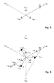
- FIG. 5 shows the compensation currents IL ca , IL ab and IL bc , which are used to compensate for the asymmetrical three-phase system according to FIG. 3. It can be seen that compensation currents flow in all phases - namely with an amplitude of 1/3 pu for each of the compensation currents IL ca , IL ab and IL bc - which makes it evident that not only reactive power but also active power is exchanged between the branches. This takes place via the energy buffer store mentioned or via the energy storage unit 7 according to FIGS. 1 and 2.
- the compensation currents are likewise symmetrical, ie they have identical amplitudes and corresponding phase differences of 120 °.
- FIG. 6 shows the vector diagram for the compensation of the asymmetrical load R according to FIG. 3.
- the current in the branches ca and bc is no longer only reactive, but there is an exchange of active power between branches via an energy buffer.
- 6 shows, for example, the projection of the current vector IL ca onto the voltage vector u ca the active component of the current.
- the compensator according to the invention consumes active power, in other words energy is stored in the intermediate storage unit 7 (FIGS. 1 and 2). The stored energy is in the branches from fed back, so that the energy in the storage unit 7 remains constant on average.
- the above use cases relate to a pure resistance load.
- the invention is also suitable also to compensate for any impedances that as is well known, a real and an imaginary part have, the latter for an inductive or capacitive Standing portion.
- the advantages shown apply in in the same way for any impedance.
- the energy storage unit stored energy arbitrarily on the individual branches of the Multiphase system can be distributed. This can be for more Compensation purposes are used. So it is conceivable that with the help of the teaching according to the invention instead of Compensate for the fundamental wave as above has been explained in detail, a compensation of Harmonics is achieved. Of course they can Fundamental wave and any harmonics at the same time be compensated. In this case it can be totally Available power may be greater than that above specified 3 * 1/3 pu. The power actually required depends essentially on the desired division of the required power depends on the individual branches.
Landscapes
- Engineering & Computer Science (AREA)
- Power Engineering (AREA)
- Supply And Distribution Of Alternating Current (AREA)
- Ac-Ac Conversion (AREA)
Abstract
Description
- Fig. 1
- in schematischer Darstellung, eine Anordnung zur Kompensation von asymmetrischen Lasten bei einem Dreiphasensystem,
- Fig. 2
- eine spezifische Ausführungsform der Anordnung gemäss Fig. 1,
- Fig. 3
- ein Ersatzschaltbild eines asymmetrischen Dreiphasesystems,
- Fig. 4
- ein Zeigerdiagramm des mittels einer Steinmetz-Schaltung kompensierten asymmetrischen Dreiphasensystems gemäss Fig. 3,
- Fig. 5 und 6
- Zeigerdiagramme des mittels dem erfindungsgemässen Verfahren kompensierten asymmetrischen Dreiphasensystem gemäss Fig. 3.

Claims (11)
- Verfahren zur Kompensation von asymmetrischen Lasten in Mehrphasensystemen, dadurch gekennzeichnet, dass mit einer Kompensationseinheit (5) Kompensationsströme (ILab, ILbc, ILca) erzeugt werden, die beliebige Phasen und/oder beliebige Amplituden aufweisen.
- Verfahren nach Anspruch 1, dadurch gekennzeichnet, dass zur Erzeugung der Kompensationsströme (ILab, ILbc, ILca) Energie einer Energiespeichereinheit (7) zugeführt bzw. entnommen wird.
- Verfahren nach Anspruch 1 oder 2, dadurch gekennzeichnet, dass die Amplituden der Kompensationsströme (ILab, ILbc, ILca) im wesentlichen gleich gross sind.
- Verfahren nach einem der vorangehenden Ansprüche, dass von mindestens einer Phase auf mindestens eine andere Phase Wirkleistung übertragen wird.
- Verfahren nach einem der vorangehenden Ansprüche, dadurch gekennzeichnet, dass die Kompensationsströme (ILab, ILbc, ILca) minimiert werden.
- Vorrichtung zur Durchführung des Verfahrens nach einem der Ansprüche 1 bis 5, dadurch gekennzeichnet, dass eine Kompensationseinheit (5), bestehend aus einer Schalteinheit (6) und einer Energiespeichereinheit (7), vorgesehen ist, wobei die Energiespeichereinheit (7) über die Schalteinheit (6) mit einem Mehrphasensystem verbindbar ist.
- Vorrichtung nach Anspruch 6, dadurch gekennzeichnet, dass die Schalteinheit (6) über einen Transformator (4) an das Mehrphasensystem anschliessbar ist.
- Vorrichtung nach Anspruch 6 oder 7, dadurch gekennzeichnet, dass eine Ladeeinheit (8) vorgesehen ist, die eingangsseitig mit der Energiespeichereinheit (7) und ausgangsseitig mit dem Mehrphasensystem verbindbar ist.
- Vorrichtung nach einem der Ansprüche 6 bis 8, dadurch gekennzeichnet, dass die Energiespeichereinheit (7) als Kondensator realisiert ist.
- Vorrichtung nach einem der Ansprüche 6 bis 9, dadurch gekennzeichnet, dass die Schalteinheit (6) aus GTO-(Gate-Turn-Off)-Thyristoren oder IGBT-(Insulated-Gate-Bipolar-Transistor) bestehen.
- Verwendung der Vorrichtung nach einem der Ansprüche 6 bis 10 zur Kompensation von asymmetrischen Lasten bei Dreiphasensystemen.
Applications Claiming Priority (2)
| Application Number | Priority Date | Filing Date | Title |
|---|---|---|---|
| DE19944917A DE19944917A1 (de) | 1999-09-20 | 1999-09-20 | Verfahren zur Kompensation von asymmetrischen Lasten in Mehrphasensystemen |
| DE19944917 | 1999-09-20 |
Publications (3)
| Publication Number | Publication Date |
|---|---|
| EP1085637A2 true EP1085637A2 (de) | 2001-03-21 |
| EP1085637A3 EP1085637A3 (de) | 2003-02-05 |
| EP1085637B1 EP1085637B1 (de) | 2007-02-07 |
Family
ID=7922581
Family Applications (1)
| Application Number | Title | Priority Date | Filing Date |
|---|---|---|---|
| EP00810836A Expired - Lifetime EP1085637B1 (de) | 1999-09-20 | 2000-09-15 | Verfahren zur Kompensation von asymmetrischen Lasten in Mehrphasensystemen |
Country Status (4)
| Country | Link |
|---|---|
| US (1) | US6333863B1 (de) |
| EP (1) | EP1085637B1 (de) |
| CA (1) | CA2320001A1 (de) |
| DE (2) | DE19944917A1 (de) |
Families Citing this family (1)
| Publication number | Priority date | Publication date | Assignee | Title |
|---|---|---|---|---|
| CN112531695B (zh) * | 2020-11-27 | 2022-09-06 | 国网湖南省电力有限公司 | 一种电能质量分支自适应补偿方法及系统 |
Family Cites Families (4)
| Publication number | Priority date | Publication date | Assignee | Title |
|---|---|---|---|---|
| JP2888104B2 (ja) * | 1993-09-01 | 1999-05-10 | 株式会社日立製作所 | 電力変換装置 |
| KR100214686B1 (ko) * | 1997-04-10 | 1999-08-02 | 이종수 | 엘리베이터의 구출운전 겸용 역률 개선장치 |
| DE19737590C1 (de) * | 1997-08-28 | 1998-10-22 | Siemens Ag | Verfahren und Vorrichtung zur Verbesserung der Spannungsqualität eines unterlagerten Netzteiles |
| EP0954082A3 (de) * | 1998-04-10 | 1999-11-24 | Kabushiki Kaisha Toshiba | Wechselstromübertragungssystem |
-
1999
- 1999-09-20 DE DE19944917A patent/DE19944917A1/de not_active Withdrawn
-
2000
- 2000-09-15 DE DE50014033T patent/DE50014033D1/de not_active Expired - Fee Related
- 2000-09-15 EP EP00810836A patent/EP1085637B1/de not_active Expired - Lifetime
- 2000-09-19 US US09/664,092 patent/US6333863B1/en not_active Expired - Fee Related
- 2000-09-20 CA CA002320001A patent/CA2320001A1/en not_active Abandoned
Non-Patent Citations (6)
| Title |
|---|
| "Active Filter and Power Conditioner for Distribution Networks Sipcon P/S" POWER QUALITY CATALOG SR 10.5, [Online] 1998, XP002222141 Gefunden im Internet: <URL:http://www.siemens.cz/siemens/site/EN ERGIE/ev/ev_s/sekundarni_technika/katalog/ Kvalita_energie/uprava_kvality_energie/Sip con_PS_aktivni_filtr_en.pdf> [gefunden am 2002-11-22] * |
| G. M[RZ: "Die Blindleistungsschwankungen bei Lichtbogenöfen und ihre Kompensation mit Hilfe elektronisch regelbarer Phasenschieber" ELEKTROW[RME INTERNATIONAL, Februar 1972 (1972-02), XP000112017 * |
| L GYUNGY: "Principles and Applications of Static Thyristor-Controlled Shunt Compensators" IEEE TRANSACTIONS ON POWER APPARATUS AND SYSTEMS, Bd. 97, Nr. 5, 1978, Seiten 1935-1945, XP001120178 * |
| MANGOLD TH ET AL: "Netqualit{t im Griff" EV REPORT, XX, DE, Bd. 4, Nr. 4, 1996, Seiten 16-18, XP002091234 ISSN: 0938-0043 * |
| SONNENSCHEIN M ET AL: "Shunt-connected power conditioner for improvement of power quality in distribution networks" PROCEEDINGS OF THE ICHQP. INTERNATIONAL CONFERENCE ON HARMONICS AND QUALITY OF POWER, XX, XX, 18. Oktober 1996 (1996-10-18), Seiten 27-32, XP002090516 * |
| SUNDBERG: "On the balancing of single phase loads" ASEA JOURNAL, Bd. 52, Nr. 5, 1979, Seiten 119-121, XP001120176 * |
Also Published As
| Publication number | Publication date |
|---|---|
| EP1085637A3 (de) | 2003-02-05 |
| EP1085637B1 (de) | 2007-02-07 |
| CA2320001A1 (en) | 2001-03-20 |
| US6333863B1 (en) | 2001-12-25 |
| DE19944917A1 (de) | 2001-03-22 |
| DE50014033D1 (de) | 2007-03-22 |
Similar Documents
| Publication | Publication Date | Title |
|---|---|---|
| EP3172823B1 (de) | Gleichspannungswandler mit transformator | |
| DE2950247C2 (de) | Stromversorgungssystem | |
| EP2329684B1 (de) | Stromversorgungsanlage für einen drehstrom-lichtbogenofen mit zwischenkreisumrichter zwischen netzanschluss und ofentransformator | |
| EP0152002B1 (de) | Phasenschieber | |
| EP2596980B1 (de) | Mehrpunkt-Stromrichter mit Bremschopper | |
| EP2707944B1 (de) | Hybridumrichter und verfahren zu seiner regelung | |
| EP2348597A1 (de) | Angleichung der über die einzelnen Phasen eines mehrphasigen Wechselstroms fließenden Teilleistungen | |
| EP2994969B1 (de) | Anordnung zur kompensation von blindleistung und wirkleistung in einem hochspannungsnetz | |
| DE10128152B4 (de) | Schiffsantriebssystem mit vermindertem Bordnetzklirrfaktor | |
| EP2088668A2 (de) | Statischer Umformer | |
| EP2451065A2 (de) | Tiefsetzsteller | |
| DE102017202204A1 (de) | Umrichteranordnung | |
| DE2904817A1 (de) | Verfahren und schaltung zur steuerung eines hochspannungs-gleichstromsystems | |
| DE102017131042A1 (de) | Umrichter mit mindestens einem wandlermodul mit drei brückenzweigen, verfahren zum betreiben und verwendung eines solchen umrichters | |
| EP2966769B1 (de) | Betrieb eines modularen Multilevelstromrichters | |
| EP1085637B1 (de) | Verfahren zur Kompensation von asymmetrischen Lasten in Mehrphasensystemen | |
| WO2018113926A1 (de) | Stromrichter | |
| DE3243701C2 (de) | Verfahren und Schaltungsanordnung zur dynamischen Blindleistungskompensation und Symmetrierung von unsymmetrischen Netzen und Lasten mit Stromrichtern | |
| EP3218980B1 (de) | Verfahren zum steuern eines lastflusses in einem gleichspannungsnetz | |
| DE19742429C1 (de) | Schaltungsanordnung | |
| DE3213778C2 (de) | ||
| EP3741023B1 (de) | Vorrichtung und verfahren zum steuern eines lastflusses in einem wechselspannungsnetz | |
| DE2433825C3 (de) | Vorrichtungen zur Energieversorgung und Verbesserung des Leistungsfaktors von Wechselstromnetzen | |
| DE202020101549U1 (de) | Schaltungsanordnung mit mehreren Leistungselektronikmodulen | |
| EP3751718A1 (de) | Verfahren zur fehlerbehandlung eines fehlers in einer gleichspannungsleitung sowie eine stromrichteranordnung zum durchführen des verfahrens |
Legal Events
| Date | Code | Title | Description |
|---|---|---|---|
| PUAI | Public reference made under article 153(3) epc to a published international application that has entered the european phase |
Free format text: ORIGINAL CODE: 0009012 |
|
| AK | Designated contracting states |
Kind code of ref document: A2 Designated state(s): AT BE CH CY DE DK ES FI FR GB GR IE IT LI LU MC NL PT SE |
|
| AX | Request for extension of the european patent |
Free format text: AL;LT;LV;MK;RO;SI |
|
| RAP1 | Party data changed (applicant data changed or rights of an application transferred) |
Owner name: ABB SCHWEIZ HOLDING AG |
|
| PUAL | Search report despatched |
Free format text: ORIGINAL CODE: 0009013 |
|
| AK | Designated contracting states |
Designated state(s): AT BE CH CY DE DK ES FI FR GB GR IE IT LI LU MC NL PT SE |
|
| AX | Request for extension of the european patent |
Extension state: AL LT LV MK RO SI |
|
| AKX | Designation fees paid |
Designated state(s): CH DE FR GB IT LI SE |
|
| 17P | Request for examination filed |
Effective date: 20030521 |
|
| 17Q | First examination report despatched |
Effective date: 20031216 |
|
| RAP1 | Party data changed (applicant data changed or rights of an application transferred) |
Owner name: ABB SCHWEIZ AG |
|
| GRAP | Despatch of communication of intention to grant a patent |
Free format text: ORIGINAL CODE: EPIDOSNIGR1 |
|
| GRAS | Grant fee paid |
Free format text: ORIGINAL CODE: EPIDOSNIGR3 |
|
| GRAA | (expected) grant |
Free format text: ORIGINAL CODE: 0009210 |
|
| AK | Designated contracting states |
Kind code of ref document: B1 Designated state(s): CH DE FR GB IT LI SE |
|
| REG | Reference to a national code |
Ref country code: GB Ref legal event code: FG4D Free format text: NOT ENGLISH |
|
| REG | Reference to a national code |
Ref country code: CH Ref legal event code: EP |
|
| REF | Corresponds to: |
Ref document number: 50014033 Country of ref document: DE Date of ref document: 20070322 Kind code of ref document: P |
|
| PG25 | Lapsed in a contracting state [announced via postgrant information from national office to epo] |
Ref country code: SE Free format text: LAPSE BECAUSE OF FAILURE TO SUBMIT A TRANSLATION OF THE DESCRIPTION OR TO PAY THE FEE WITHIN THE PRESCRIBED TIME-LIMIT Effective date: 20070507 |
|
| GBT | Gb: translation of ep patent filed (gb section 77(6)(a)/1977) |
Effective date: 20070416 |
|
| ET | Fr: translation filed | ||
| PLBE | No opposition filed within time limit |
Free format text: ORIGINAL CODE: 0009261 |
|
| STAA | Information on the status of an ep patent application or granted ep patent |
Free format text: STATUS: NO OPPOSITION FILED WITHIN TIME LIMIT |
|
| 26N | No opposition filed |
Effective date: 20071108 |
|
| PG25 | Lapsed in a contracting state [announced via postgrant information from national office to epo] |
Ref country code: IT Free format text: LAPSE BECAUSE OF NON-PAYMENT OF DUE FEES Effective date: 20070915 |
|
| REG | Reference to a national code |
Ref country code: CH Ref legal event code: PL |
|
| GBPC | Gb: european patent ceased through non-payment of renewal fee |
Effective date: 20070915 |
|
| PG25 | Lapsed in a contracting state [announced via postgrant information from national office to epo] |
Ref country code: DE Free format text: LAPSE BECAUSE OF NON-PAYMENT OF DUE FEES Effective date: 20080401 Ref country code: CH Free format text: LAPSE BECAUSE OF NON-PAYMENT OF DUE FEES Effective date: 20070930 Ref country code: LI Free format text: LAPSE BECAUSE OF NON-PAYMENT OF DUE FEES Effective date: 20070930 |
|
| REG | Reference to a national code |
Ref country code: FR Ref legal event code: ST Effective date: 20080531 |
|
| PG25 | Lapsed in a contracting state [announced via postgrant information from national office to epo] |
Ref country code: FR Free format text: LAPSE BECAUSE OF NON-PAYMENT OF DUE FEES Effective date: 20071001 |
|
| PG25 | Lapsed in a contracting state [announced via postgrant information from national office to epo] |
Ref country code: GB Free format text: LAPSE BECAUSE OF NON-PAYMENT OF DUE FEES Effective date: 20070915 |