EP1085633A1 - Déclencheur comportant une interface homme-machine ameliorée et disjoncteur comportant un tel déclencheur - Google Patents
Déclencheur comportant une interface homme-machine ameliorée et disjoncteur comportant un tel déclencheur Download PDFInfo
- Publication number
- EP1085633A1 EP1085633A1 EP20000410099 EP00410099A EP1085633A1 EP 1085633 A1 EP1085633 A1 EP 1085633A1 EP 20000410099 EP20000410099 EP 20000410099 EP 00410099 A EP00410099 A EP 00410099A EP 1085633 A1 EP1085633 A1 EP 1085633A1
- Authority
- EP
- European Patent Office
- Prior art keywords
- key
- trigger
- information
- parameter
- machine interface
- Prior art date
- Legal status (The legal status is an assumption and is not a legal conclusion. Google has not performed a legal analysis and makes no representation as to the accuracy of the status listed.)
- Granted
Links
- 238000010200 validation analysis Methods 0.000 claims abstract description 17
- 238000005259 measurement Methods 0.000 claims abstract description 13
- 238000012986 modification Methods 0.000 claims abstract description 13
- 230000004048 modification Effects 0.000 claims abstract description 13
- 238000012423 maintenance Methods 0.000 claims abstract description 6
- 230000006870 function Effects 0.000 claims description 39
- 230000009471 action Effects 0.000 claims description 28
- 230000008859 change Effects 0.000 claims description 11
- 238000004891 communication Methods 0.000 claims description 9
- 238000012545 processing Methods 0.000 claims description 9
- 239000004020 conductor Substances 0.000 claims description 6
- 230000000007 visual effect Effects 0.000 claims description 6
- 238000006073 displacement reaction Methods 0.000 claims description 4
- 238000000034 method Methods 0.000 claims description 2
- 230000007935 neutral effect Effects 0.000 abstract description 3
- 238000012360 testing method Methods 0.000 abstract description 3
- 230000001681 protective effect Effects 0.000 abstract 2
- 230000004069 differentiation Effects 0.000 abstract 1
- 230000008719 thickening Effects 0.000 abstract 1
- 238000010586 diagram Methods 0.000 description 3
- 241000287107 Passer Species 0.000 description 1
- 230000004913 activation Effects 0.000 description 1
- 230000001174 ascending effect Effects 0.000 description 1
- 238000012790 confirmation Methods 0.000 description 1
- 230000003247 decreasing effect Effects 0.000 description 1
- 238000010616 electrical installation Methods 0.000 description 1
- 235000021183 entrée Nutrition 0.000 description 1
- 238000009434 installation Methods 0.000 description 1
- 230000007246 mechanism Effects 0.000 description 1
- 230000009993 protective function Effects 0.000 description 1
Images


Classifications
-
- H—ELECTRICITY
- H02—GENERATION; CONVERSION OR DISTRIBUTION OF ELECTRIC POWER
- H02H—EMERGENCY PROTECTIVE CIRCUIT ARRANGEMENTS
- H02H3/00—Emergency protective circuit arrangements for automatic disconnection directly responsive to an undesired change from normal electric working condition with or without subsequent reconnection ; integrated protection
- H02H3/006—Calibration or setting of parameters
-
- H—ELECTRICITY
- H01—ELECTRIC ELEMENTS
- H01H—ELECTRIC SWITCHES; RELAYS; SELECTORS; EMERGENCY PROTECTIVE DEVICES
- H01H71/00—Details of the protective switches or relays covered by groups H01H73/00 - H01H83/00
- H01H2071/006—Provisions for user interfaces for electrical protection devices
-
- H—ELECTRICITY
- H02—GENERATION; CONVERSION OR DISTRIBUTION OF ELECTRIC POWER
- H02H—EMERGENCY PROTECTIVE CIRCUIT ARRANGEMENTS
- H02H3/00—Emergency protective circuit arrangements for automatic disconnection directly responsive to an undesired change from normal electric working condition with or without subsequent reconnection ; integrated protection
- H02H3/02—Details
- H02H3/04—Details with warning or supervision in addition to disconnection, e.g. for indicating that protective apparatus has functioned
-
- H—ELECTRICITY
- H02—GENERATION; CONVERSION OR DISTRIBUTION OF ELECTRIC POWER
- H02H—EMERGENCY PROTECTIVE CIRCUIT ARRANGEMENTS
- H02H3/00—Emergency protective circuit arrangements for automatic disconnection directly responsive to an undesired change from normal electric working condition with or without subsequent reconnection ; integrated protection
- H02H3/08—Emergency protective circuit arrangements for automatic disconnection directly responsive to an undesired change from normal electric working condition with or without subsequent reconnection ; integrated protection responsive to excess current
- H02H3/093—Emergency protective circuit arrangements for automatic disconnection directly responsive to an undesired change from normal electric working condition with or without subsequent reconnection ; integrated protection responsive to excess current with timing means
- H02H3/0935—Emergency protective circuit arrangements for automatic disconnection directly responsive to an undesired change from normal electric working condition with or without subsequent reconnection ; integrated protection responsive to excess current with timing means the timing being determined by numerical means
Definitions
- Human-machine interfaces to adjust the trigger parameters.
- Human-machine interfaces generally include screens for viewing said adjustment parameters and display of electrical magnitude values, in particular the values of circulating currents in the contacts of a circuit breaker. It is also known to use a keyboard or keys to select preset adjustment parameters for example threshold parameters or trigger function timers.
- a trip unit with a man-machine interface with a flat screen display is described in particular in patents FR 2,654,539 and US5,220,479. In these documents the screen graphically displays the shape of the trigger curve, parameter indications settings, and current values.
- known human-machine interfaces or user interfaces do not allow not a secure setting of parameters.
- known interfaces use menus that do not sufficiently identify the current adjustment maneuvers.
- the object of the invention is a trigger comprising an improved man-machine interface allowing you to adjust parameters or view information easily and safe, as well as a circuit breaker comprising such a trip device.
- the man-machine interface comprises means display of adjustment parameters which modify the visual appearance of at least a portion of curve representative of a parameter being adjusted.
- the means for displaying adjustment parameters modify the visual appearance of at least one portion of the curve by increasing the thickness of said curve at least one portion of the curve representative of a parameter being adjusted.
- the means for displaying adjustment parameters frame at least one information displayed on the screen representative of a parameter being adjusted.
- the means for displaying adjustment parameters change at least one text or background color of at least one item of information displayed on the screen representative of a parameter being modified.
- the man-machine interface includes means display of a drop-down menu to frame during a selection phase at least one information to select.
- the display means frame information in a drop-down menu. upper stop, information in lower stop, and information scrolling in a frame fixed intermediate position between a high position and a low position.
- the man-machine interface includes means for selection comprising function keys associated with indicators to display a function selected by a key.
- the function keys comprise at least a first key for select a measurement function, at least a second key to select a maintenance function, and a third key to select an adjustment function.
- the trigger comprises a man-machine interface connected by means of communication to the processing unit.
- the means of communication communicate according to a protocol of the type Internet.
- the man-machine interface is represented on a screen to display information and trigger curves and to determine adjustment parameters.
- adjustment parameters are determined by keys represented on a human-machine interface screen.
- a circuit breaker according to the invention comprising main contacts connected in series with power conductors, current sensors disposed on said conductors, and a trip relay receiving a trip signal to cause opening of said contacts, comprises a trigger as defined above connected to said sensors for current and said trip relay.
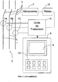
- FIG. 1 shows a circuit breaker including a trigger of the art prior.
- main conductors 1 are connected in series with contacts 2 intended to interrupt an electric current in a distribution network 3.
- Current sensors 4A, 4B, 4C supply signals to a processing unit 5 representative of current flowing in the main conductors.
- Processing unit 5 performs in particular the protective functions and provides a trigger signal to a relay 6 if current signals exceed predetermined protection curves.
- the tripping curves are representative of long-delay protection functions, short delay, instantaneous and / or zero sequence.
- Trigger relay 6 controls a mechanism 7 for opening contacts when controlled by the processing unit.
- the settings for the trigger curves are preferably made using a human-machine interface 8 connected to the processing unit.
- the interface 8 has a screen 9 and a keyboard or keys 10.
- the man-machine interface provides setting parameters and displays information and trigger curves.
- a human-machine interface of a trip device according to the invention contributes to the safety of an installation by avoiding the risks errors and making adjustments easier.
- the man-machine interface comprises means adjustment displays which modify the visual impact of at least one portion of the curve representative of a parameter being adjusted.
- a display screen 11 graphic or semi-graphic displays a trigger curve 12.
- a portion of curve 13 representative of a long-delay current threshold or thermal protection has a different visual appearance.
- this portion of the curve is thicker than the rest of the curve, while the portion of the curve is widened, a parameter 14 corresponding to this portion of the curve is framed.
- the long-delay trigger threshold is 1000A.
- the boxed parameter can also change to bold to reinforce the viewing the selection.
- the human-machine interface includes function selection keys and moving and viewing.
- the function selection keys include a first key 15 to select a measurement function, a second key 16 of maintenance selection, and a third button 17 for selecting the adjustment function.
- the movement and validation keys include a key 18 for incrementing value or moving a drop-down menu in a first direction, a key 19 of decrement value or move menu in a second direction, and a key 20 of confirmation.
- each function key 15, 16, 17 is associated with an indicator respectively 21, 22, 23.
- the key 17 is selected and the associated indicator light 23 is lit to show that the parameter setting is selected.
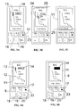
- FIGS. 3A to 3C show a cycle for selecting parameters.
- the key 17 is selected and the indicator 23 is lit.
- Key 17 selects the adjustment function.
- the portion 13 of the curve is thicker and the corresponding parameter 14 is framed.
- pressing the key 18 or 19 changes the parameter to be selected.
- it can select a portion 24 of the curve and a corresponding parameter 25 as in the representation of FIG. 3B.
- the selected parameter is the value of the delay of the long-delay function.
- Other actions on keys 18 and 19 can circulate the selection to other functions concerning the curve.
- the selection is made on an action parameter 26 concerning the exceeding of the curve.
- the parameter can relate to triggering alone, or possibly a tripping with an alarm signal or the control of an output relay.
- Figures 4A and 4B show an adjustment phase.
- pressing the key validation 20 switches the parameter to adjustment or modification mode.
- the parameter selected and framed then switches to different display mode, preferably in video reverse as in the representation of FIG. 4B.
- Figure 4A shows the interface before an action on the validation key 20
- FIG. 4B shows the interface after the action on said key 20.
- the different display mode can also be a change of color text and / or background.
- pressing the keys 18 or 19 makes it possible to modify the values of the selected parameter. In this case, a change in the protection threshold value long delay is possible.
- a new action on the validation key 20 returns to selection mode and to choose other parameters or exit the setting function.
- FIGS. 5A to 5D represent the progress of a menu during a selection phase of information. Information selection can be performed regardless of the function desired. For example, in FIGS. 5A to 5D, the selection of information is carried out with the second key 16 of the selected maintenance function. LED 22 is then active.
- the keys 18 and 19 allow in this case to frame an item of information to be selected.
- the selection is therefore made by moving a frame 29 to select information or by moving the information menu according to the position of said frame.
- the frame can be in a high stop position 26 in a low stop position 27 or in intermediate positions.
- An intermediate position 28 between the upper stop and the lower stop is determined to circulate the information menu if the number of information is greater than the number of lines of the screen intended for the display of said information.
- the number of positions is five, the stop high 26 is on the first line, low stop 27 is on the fifth line, and the stop intermediate 28 is on the third line.
- the frame 29 moves from the first information 30 to the second information 31 then to third information 32. If the frame is in a intermediate position 28, then the information scrolls upwards. So a information 33 goes back into the frame in intermediate position 28, information 34 in sixth row appears on the screen and the first information 31 disappears. When the last information appears, the frame can then move to the bottom stop position.
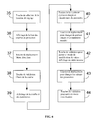
- FIG. 6 represents a flowchart which shows the passage from a drop-down menu to a parameter adjustment and modification phase.
- the selection key 17 is actuated at a step 35.
- a list of parameter functions is displayed on screen 11. This list includes in particular the protection curves, for example long-delay, short-delay or earth protection.
- a drop-down menu is activated at using the keys 18 and 19 as for example, in FIGS. 5A to 5D.
- the validation key 20 is pressed to display, at a step 39, the curve or function chosen and the corresponding parameters.
- a portion of the curve is displayed in enlarged thickness and the parameter correspondent is framed.
- the movement keys 18 and 19 allow you to change of the curve portion and of the parameter framed in a step 41.
- an action on the validation key in a step 42 puts the interface in mode change in value.
- the display of the parameter is then in reverse video.
- the movement keys 18 and 19 allow the values of parameters, for example, by scrolling through predetermined parameter values selected during adjustment.
- an action on the validation key 20 allows to save the new value of the parameter and to exit the modification mode of values.
- the man-machine interface can advantageously be associated with adjustment means manual or remote control means connected by means of communication.
- manual adjustment means When manual adjustment means are activated, the interface automatically switches to parameter setting mode and the value determined by manual setting means is displayed.
- the manual adjustment means can advantageously be switches or encoder wheels which do not necessarily require the presence of a display or a human-machine interface.
- the values of parameters that can be changed by the interface are limited to maximum values said parameters determined by the manual adjustment means. For example, if the means manual settings assign a long-delay protection threshold and a time delay long-delay protection, the interface will allow adjustment of the parameters concerned between minimum values and the values of thresholds and long-delay timers determined by the manual adjustment means.
- the manual adjustment means can be locked, for example, by a cover which prevents maneuvers after adjustment by authorized persons and the interface man-machine can be left accessible to other personnel.
- the cut current can thus be displayed.
- Average electrical quantities described above can also be displayed, these averages being calculated over configurable durations.
- the relay parameter configuration functions allow you to select a input quantity, a threshold, a direction of exceeding the increasing or decreasing threshold and the presence or absence of a hysteresis cycle.
- the input variable can for example be a current, voltage, power, temperature value, or frequency.
- the communication protocol may advantageously be Internet type, in particular in the so-called "TCP / IP” format or in the hypertext format called "HTTP”.
- the human-machine interface may, for example, be represented on a computer screen to display information and trigger curves and to determine parameters adjustment.
- adjustment parameters are determined by keys shown on the human-machine interface screen.
- the movement of a cursor on a key can in particular make it possible to select and then actuate said key materialized by an image on the screen.
Landscapes
- Breakers (AREA)
- Emergency Protection Circuit Devices (AREA)
Abstract
Description
- une unité de traitement ayant des entrées pour recevoir des signaux électriques représentatifs de grandeurs électriques et une sortie pour fournir un signal de déclenchement à un relais de déclenchement, et
- une interface homme-machine connectée à l'unité de traitement pour fournir des paramètres de réglages et afficher sur un écran des informations et des courbes de déclenchement.
- une étape d'action sur une touche de sélection de fonction de réglage,
- une étape d'affichage d'une liste de courbes de protection,
- une étape d'action sur au moins une touche de déplacement dans un menu déroulant,
- une étape d'action sur une touche de validation pour sélectionner une courbe à paramétrer,
- une étape d'affichage d'une courbe sélectionnée et de paramètres de réglages correspondants,
- une étape d'affichage d'une portion de courbe sélectionnée en épaisseur élargie et d'un paramètre correspondant avec un cadre,
- une étape d'action sur au moins une touche de déplacement pour changer de portion de courbe et de paramètre correspondant,
- une étape d'action sur une touche de validation pour passer en mode de modification de valeur de paramètre,
- une étape d'action sur une touche de déplacement pour changer des valeurs de paramètres, et
- une étape d'action sur au moins une touche de validation pour sortir du mode de modification.
- la figure 1 représente le schéma d'un disjoncteur comprenant un déclencheur de l'art antérieur,
- la figure 2 représente une interface homme-machine d'un déclencheur selon un mode réalisation de l'invention,
- les figures 3A à 3C représentent des sélections de paramètres à régler,
- les figures 4A et 4B représentent une phase de réglage,
- les figures 5A à 5D représentent le déroulement d'un menu lors d'une phase de sélection d'informations,
- la figure 6 représente un organigramme d'une phase de réglage.
- des mesures de courant de phase et de neutre,
- des mesures de courant homopolaire ou de terre,
- des mesures de tension entre phase et neutre ou entre deux phases,
- des mesures de puissance apparente, active, ou réactive,
- des mesures d'énergie,
- des mesures de fréquence, et/ou
- des mesures de facteur de puissance ou de facteur de crête.
- des historiques de déclenchement en indiquant le type de défaut, la date et l'heure, et les valeurs mesurées à l'instant du défaut, par exemple le courant coupé,
- des historiques d'alarmes en indiquant par exemple le type d'alarme, la date, l'heure et les valeurs mesurées à l'activation de l'alarme,
- l'affichage d'informations représentatives de l'usure de contacts, d'un compteur de manoeuvres ou de température,
- des fonctions de commande de relais,
- des fonctions de configuration de paramètres de communication sur un réseau, et/ou
- des fonctions de configuration de paramètres de test.
- des courbes de protection long-retard, court-retard, et instantanée,
- des courbes de protection terre,
- des courbes de protection différentielle,
- des alarmes en déséquilibre de tension, en maximum de tension, ou en minimum de tension,
- des alarmes en maximum de puissance ou en retour de puissance,
- des alarmes en minimum ou en maximum de fréquence,
- des indications sur le sens de rotation des phases, et/ou
- des fonctions de délestage, re lestage en fonction des valeurs de courant ou de puissance.
Claims (14)
- Déclencheur électronique comportant :déclencheur caractérisé en ce que l'interface homme-machine comporte des moyens d'affichage (11) de paramètres de réglage qui modifient l'aspect visuel d'au moins une portion (13, 24) de courbe (12) représentative d'un paramètre (14, 25) en cours de réglage.une unité de traitement (5) ayant des entrées pour recevoir des signaux électriques représentatifs de grandeurs électriques et une sortie pour fournir un signal de déclenchement à un relais (6) de déclenchement, etune interface homme-machine (8) connectée à l'unité de traitement pour fournir des paramètres de réglages et afficher sur un écran (9) des informations et des courbes de déclenchement,
- Déclencheur selon la revendication 1, caractérisé en ce que les moyens d'affichage (11) de paramètres de réglage modifient l'aspect visuel d'au moins une portion (13, 24) de courbe (12) en augmentant l'épaisseur de ladite au moins une portion de courbe représentative d'un paramètre en cours de réglage.
- Déclencheur selon l'une des revendications 1 ou 2, caractérisé en ce que les moyens d'affichage (11) de paramètres de réglage encadrent au moins une information (14, 25) affichée sur l'écran représentative d'un paramètre en cours de réglage.
- Déclencheur selon l'une quelconque des revendications 1 à 3, caractérisé en ce que les moyens d'affichage (11) de paramètres de réglage changent au moins une couleur de texte ou de fond d'au moins une information (14, 25) affichée sur l'écran représentative d'un paramètre en cours de modification de valeur.
- Déclencheur selon l'une quelconque des revendications 1 à 4, caractérisé en ce que l'interface homme-machine comporte des moyens d'affichage (11) d'un menu déroulant pour encadrer (29) lors d'une phase de sélection au moins une information (31-34) à sélectionner.
- Déclencheur selon la revendication 5, caractérisé en ce que les moyens d'affichage encadrent dans un menu déroulant une information en butée haute (26), une information en butée basse (27), et des informations déroulant dans un cadre en position fixe (28) intermédiaire entre une position haute (26) et une position basse (27).
- Déclencheur selon l'une quelconque des revendications 1 à 6, caractérisé en ce que l'interface homme-machine comporte des moyens de sélection comportant des touches de fonctions (15, 16, 17) associées à des voyants (21, 22, 23) pour visualiser une fonction sélectionnée par une touche.
- Déclencheur selon la revendication 7, caractérisé en ce que les touches de fonction (15, 16, 17) comportent au moins une première touche (15) pour sélectionner une fonction de mesure, au moins une seconde touche (16) pour sélectionner une fonction de maintenance, et une troisième touche (17) pour sélectionner une fonction de réglage.
- Déclencheur selon l'une des revendications 7 ou 8, paramètré selon un procédé caractérisé en ce qu'il comporte :une étape (35) d'action sur une touche (17) de sélection de fonction de réglage,une étape (36) d'affichage d'une liste de courbes de protection,une étape (37) d'action sur au moins une touche (18, 19) de déplacement dans un menu déroulant,une étape (38) d'action sur une touche de validation (20) pour sélectionner une courbe à paramétrer,une étape (39) d'affichage d'une courbe sélectionnée et de paramètres de réglages correspondants,une étape (40) d'affichage d'une portion de courbe sélectionnée en épaisseur élargie et d'un paramètre correspondant avec un cadre,une étape (41) d'action sur au moins une touche (18, 19) de déplacement pour changer de portion de courbe et de paramètre correspondant,une étape (42) d'action sur une touche (20) de validation pour passer en mode de modification de valeur de paramètre,une étape (43) d'action sur une touche de déplacement (18, 19) pour changer des valeurs de paramètres (14, 25), etune étape (44) d'action sur au moins une touche (20) de validation pour sortir du mode de modification.
- Déclencheur selon l'une quelconque des revendications 1 à 9 caractérisé en ce que l'interface homme-machine est connectée par des moyens de communication à l'unité de traitement.
- Déclencheur selon la revendication 10 caractérisé en ce que les moyens de communication communiquent selon un protocole de type Internet.
- Déclencheur selon l'une quelconque des revendications 1 à 11 caractérisé en ce que l'interface homme-machine est représentée sur un écran pour afficher des informations et des courbes de déclenchement et pour déterminer des paramètres de réglage.
- Déclencheur selon la revendication 12 caractérisé en ce que des paramètres de réglage sont déterminés par des touches représentées sur un écran de l'interface homme-machine.
- Disjoncteur comportant des contacts principaux (2) connectés en série avec des conducteurs (1) de puissance, des capteurs (4A, 4B, 4C) de courant disposés sur lesdits conducteurs, et un relais (6) de déclenchement recevant un signal de déclenchement pour provoquer l'ouverture desdits contacts, caractérisé en ce qu'il comporte un déclencheur selon l'une quelconque des revendications 1 à 13, connecté audits capteurs de courant et audit relais de déclenchement.
Applications Claiming Priority (2)
| Application Number | Priority Date | Filing Date | Title |
|---|---|---|---|
| FR9911549 | 1999-09-13 | ||
| FR9911549A FR2798524B1 (fr) | 1999-09-13 | 1999-09-13 | Declencheur comportant une interface homme-machine amelioree et disjoncteur comportant un tel dispositif |
Publications (2)
| Publication Number | Publication Date |
|---|---|
| EP1085633A1 true EP1085633A1 (fr) | 2001-03-21 |
| EP1085633B1 EP1085633B1 (fr) | 2016-08-17 |
Family
ID=9549880
Family Applications (1)
| Application Number | Title | Priority Date | Filing Date |
|---|---|---|---|
| EP00410099.6A Expired - Lifetime EP1085633B1 (fr) | 1999-09-13 | 2000-08-18 | Déclencheur comportant une interface homme-machine ameliorée et disjoncteur comportant un tel déclencheur |
Country Status (5)
| Country | Link |
|---|---|
| US (1) | US6798630B1 (fr) |
| EP (1) | EP1085633B1 (fr) |
| JP (1) | JP2001112161A (fr) |
| CN (1) | CN1190815C (fr) |
| FR (1) | FR2798524B1 (fr) |
Cited By (4)
| Publication number | Priority date | Publication date | Assignee | Title |
|---|---|---|---|---|
| DE102005016105A1 (de) * | 2005-04-08 | 2006-10-12 | Moeller Gmbh | Verfahren zum Ein- und Darstellen der Auslösekennlinie von Schutzschaltern |
| EP2068336A1 (fr) * | 2007-12-05 | 2009-06-10 | ABB Technology AG | Relais de protection et son interface homme-machine |
| ITMI20081579A1 (it) * | 2008-09-03 | 2010-03-04 | Abb Spa | Un dispositivo d'interfaccia utente per dispositivi di commutazione in bassa tensione. |
| CN102427005A (zh) * | 2011-09-08 | 2012-04-25 | 常熟开关制造有限公司(原常熟开关厂) | 一种断路器保护参数自动整定方法 |
Families Citing this family (65)
| Publication number | Priority date | Publication date | Assignee | Title |
|---|---|---|---|---|
| FR2865582B1 (fr) * | 2004-01-22 | 2006-03-10 | Schneider Electric Ind Sas | Dispositif de protection differentielle avec moyens de reglage simplifies des parametres de protection |
| JP2007085988A (ja) * | 2005-09-26 | 2007-04-05 | Xanavi Informatics Corp | ナビゲーション装置 |
| CN101375361A (zh) * | 2006-04-29 | 2009-02-25 | 埃伦贝格尔及珀恩斯根有限公司 | 电子保护开关 |
| FR2900637B1 (fr) * | 2006-05-04 | 2009-02-13 | Airbus France Sas | Dispositif et procede pour gerer l'activation ou la desactivation des alimentations electriques des systemes electriques a bord d'un aeronef |
| US7996282B1 (en) | 2006-09-29 | 2011-08-09 | Amazon Technologies, Inc. | Method and system for selecting and displaying items |
| JP4939954B2 (ja) * | 2007-01-24 | 2012-05-30 | 三菱電機株式会社 | 電力制限器 |
| JP5081467B2 (ja) * | 2007-02-16 | 2012-11-28 | パナソニック株式会社 | 電子式ブレーカ |
| JP5081466B2 (ja) * | 2007-02-16 | 2012-11-28 | パナソニック株式会社 | 電子式ブレーカ |
| USD580941S1 (en) * | 2007-03-30 | 2008-11-18 | Amazon Technologies, Inc. | User interface for a portion of a display screen |
| US9075492B1 (en) | 2007-03-30 | 2015-07-07 | Amazon Technologies, Inc. | Method and system for displaying items |
| USD571819S1 (en) | 2007-03-30 | 2008-06-24 | Amazon Technologies, Inc. | User interface for a portion of a display screen |
| USD571820S1 (en) | 2007-03-30 | 2008-06-24 | Amazon Technologies, Inc. | User interface for a portion of a display screen |
| USD573603S1 (en) | 2007-03-30 | 2008-07-22 | Amazon Technologies, Inc. | User interface for a portion of a display screen |
| USD573602S1 (en) | 2007-03-30 | 2008-07-22 | Amazon Technologies, Inc. | User interface for a portion of a display screen |
| USD620020S1 (en) * | 2007-06-23 | 2010-07-20 | Apple Inc. | Graphical user interface for a display screen or portion thereof |
| US7995314B2 (en) * | 2007-12-03 | 2011-08-09 | Siemens Industry, Inc. | Devices, systems, and methods for managing a circuit breaker |
| USD693361S1 (en) | 2011-02-03 | 2013-11-12 | Microsoft Corporation | Display screen with transitional graphical user interface |
| USD669494S1 (en) * | 2011-02-03 | 2012-10-23 | Microsoft Corporation | Display screen with graphical user interface |
| USD669495S1 (en) * | 2011-02-03 | 2012-10-23 | Microsoft Corporation | Display screen with graphical user interface |
| USD671140S1 (en) * | 2011-02-03 | 2012-11-20 | Microsoft Corporation | Display screen with graphical user interface |
| USD669493S1 (en) * | 2011-02-03 | 2012-10-23 | Microsoft Corporation | Display screen with graphical user interface |
| USD669491S1 (en) * | 2011-02-03 | 2012-10-23 | Microsoft Corporation | Display screen with graphical user interface |
| USD669488S1 (en) * | 2011-02-03 | 2012-10-23 | Microsoft Corporation | Display screen with graphical user interface |
| USD692913S1 (en) | 2011-02-03 | 2013-11-05 | Microsoft Corporation | Display screen with graphical user interface |
| USD673169S1 (en) | 2011-02-03 | 2012-12-25 | Microsoft Corporation | Display screen with transitional graphical user interface |
| USD687841S1 (en) | 2011-02-03 | 2013-08-13 | Microsoft Corporation | Display screen with transitional graphical user interface |
| USD669489S1 (en) * | 2011-02-03 | 2012-10-23 | Microsoft Corporation | Display screen with graphical user interface |
| USD669912S1 (en) * | 2011-02-03 | 2012-10-30 | Microsoft Corporation | Display screen with graphical user interface |
| USD669490S1 (en) * | 2011-02-03 | 2012-10-23 | Microsoft Corporation | Display screen with graphical user interface |
| USD669492S1 (en) * | 2011-02-03 | 2012-10-23 | Microsoft Corporation | Display screen with graphical user interface |
| USD691620S1 (en) | 2011-06-03 | 2013-10-15 | Apple Inc. | Display screen or portion thereof with graphical user interface |
| DE102011083825A1 (de) * | 2011-09-30 | 2013-04-04 | Siemens Aktiengesellschaft | Schalter, insbesondere Leistungsschalter für Niederspannungen |
| USD682858S1 (en) * | 2011-11-18 | 2013-05-21 | Microsoft Corporation | Display screen with graphical user interface |
| USD682865S1 (en) * | 2011-11-18 | 2013-05-21 | Microsoft Corporation | Display screen with graphical user interface |
| CN102749871B (zh) * | 2012-07-16 | 2015-09-30 | 上海诺雅克电气有限公司 | 一种断路器电子式控制器及其供电方法 |
| US20140118875A1 (en) * | 2012-10-31 | 2014-05-01 | Eaton Corporation | Control and monitoring unit for a circuit interrupter electronic trip unit and system including same |
| CN103035453B (zh) * | 2012-12-10 | 2015-06-17 | 常熟开关制造有限公司(原常熟开关厂) | 一种断路器控制器及其整定方法 |
| US9331746B2 (en) * | 2012-12-19 | 2016-05-03 | Eaton Corporation | System and method for providing information to and/or obtaining information from a component of an electrical distribution system |
| USD741353S1 (en) | 2013-06-10 | 2015-10-20 | Apple Inc. | Display screen or portion thereof with animated graphical user interface |
| US9705310B2 (en) | 2013-11-26 | 2017-07-11 | Thomas & Betts International Llc | Adaptive fault clearing based on power transistor temperature |
| DE102014201505A1 (de) | 2014-01-28 | 2015-07-30 | Siemens Aktiengesellschaft | Elektrische Schutzanordnung für eine Elektroinstallation sowie dazugehöriges Verfahren |
| DE102014201501A1 (de) * | 2014-01-28 | 2015-07-30 | Siemens Aktiengesellschaft | Externe Ansteuerung eines elektromagnetischen Auslösers |
| US9847201B2 (en) | 2014-02-21 | 2017-12-19 | Eaton Corporation | Circuit protection apparatus and method of setting trip parameters thereof |
| USD783648S1 (en) * | 2015-04-12 | 2017-04-11 | Adp, Llc | Display screen with graphical user interface |
| DE102015210479B4 (de) * | 2015-06-09 | 2022-06-23 | Siemens Ag | Leistungsschalter für einen elektrischen Stromkreis |
| USD799518S1 (en) | 2016-06-11 | 2017-10-10 | Apple Inc. | Display screen or portion thereof with graphical user interface |
| USD822040S1 (en) | 2016-06-12 | 2018-07-03 | Apple Inc. | Display screen or portion thereof with graphical user interface |
| CN108074766B (zh) * | 2016-11-16 | 2019-07-02 | 浙江正泰电器股份有限公司 | 断路器控制器的脱扣单元及脱扣方法 |
| USD829223S1 (en) | 2017-06-04 | 2018-09-25 | Apple Inc. | Display screen or portion thereof with graphical user interface |
| USD857739S1 (en) | 2017-06-05 | 2019-08-27 | Apple Inc. | Display screen or portion thereof with animated graphical user interface |
| EP3691066B1 (fr) * | 2017-09-28 | 2022-10-26 | Mitsubishi Electric Corporation | Disjoncteur électronique |
| WO2019207459A1 (fr) * | 2018-04-23 | 2019-10-31 | Abb Schweiz Ag | Dispositif d'affichage de données relatives à un disjoncteur en temps réel et procédé associé |
| CN108987199A (zh) * | 2018-08-06 | 2018-12-11 | 郑州泰恩科技有限公司 | 一种电气设备开关保护装置 |
| US11233387B2 (en) * | 2019-02-08 | 2022-01-25 | Rockwell Automation Technologies, Inc. | Power system performance based on updated performance characteristics of a protection device |
| USD907053S1 (en) * | 2019-05-31 | 2021-01-05 | Apple Inc. | Electronic device with animated graphical user interface |
| USD937858S1 (en) | 2019-05-31 | 2021-12-07 | Apple Inc. | Display screen or portion thereof with graphical user interface |
| USD927507S1 (en) | 2019-08-23 | 2021-08-10 | Google Llc | Display screen or portion thereof with transitional graphical user interface |
| USD937295S1 (en) | 2020-02-03 | 2021-11-30 | Apple Inc. | Display screen or portion thereof with graphical user interface |
| CN111223725B (zh) * | 2020-03-03 | 2025-03-11 | 巨邦集团有限公司 | 一种断路器及控制方法 |
| CN116235378A (zh) | 2020-06-11 | 2023-06-06 | 恩文特服务有限责任公司 | 用于控制数字断路器的系统和方法 |
| USD949185S1 (en) | 2020-06-21 | 2022-04-19 | Apple Inc. | Display screen or portion thereof with graphical user interface |
| US11336946B1 (en) | 2020-08-19 | 2022-05-17 | Amazon Technologies, Inc. | Presenting options for selecting content via navigation bars and designated content spaces |
| USD974384S1 (en) * | 2021-03-15 | 2023-01-03 | Intrface Solutions Inc. | Display screen or portion thereof with graphical user interface |
| USD1088006S1 (en) | 2023-12-20 | 2025-08-12 | Apple Inc. | Display screen or portion thereof with graphical user interface |
| CN118713285B (zh) * | 2024-05-30 | 2025-11-14 | 科华数据股份有限公司 | 一种断路器线路保护参数的可视化处理方法、装置及终端 |
Citations (6)
| Publication number | Priority date | Publication date | Assignee | Title |
|---|---|---|---|---|
| FR2654539A1 (fr) | 1989-11-16 | 1991-05-17 | Merlin Gerin | Declencheur electronique dont la face avant est constituee par un afficheur a ecran plat. |
| US5101316A (en) * | 1988-11-02 | 1992-03-31 | Merlin Gerin | Microprocessor-based trip device with optional functions and selection process of said functions |
| US5367427A (en) * | 1993-07-15 | 1994-11-22 | Eaton Corporation | Overcurrent trip unit with indication of dependency of trip functions |
| EP0814393A1 (fr) * | 1996-06-20 | 1997-12-29 | Telia Ab | Commande et surveillance de composants électriques |
| DE19722898A1 (de) * | 1997-05-29 | 1998-12-10 | Siemens Ag | Ferngesteuerte Überwachung eines elektronischen Überstromauslösers |
| JPH11191927A (ja) * | 1997-12-25 | 1999-07-13 | Toshiba Corp | 電力系統監視制御装置とこの装置を実行するためのプログラムを記録した記録媒体 |
Family Cites Families (8)
| Publication number | Priority date | Publication date | Assignee | Title |
|---|---|---|---|---|
| US4245318A (en) * | 1979-05-07 | 1981-01-13 | General Electric Company | Circuit breaker demonstrator and distribution circuit protection coordinator apparatus |
| US5220470A (en) | 1984-11-13 | 1993-06-15 | Unisys Corporation | Method of adapting slider to include back-bar |
| JPH0827811B2 (ja) * | 1985-02-28 | 1996-03-21 | 株式会社日立製作所 | 輸送計画作成方法およびシステム |
| US4752853A (en) * | 1987-02-20 | 1988-06-21 | Westinghouse Electric Corp. | Circuit interrupter apparatus with an integral trip curve display |
| WO1996010856A1 (fr) * | 1994-09-30 | 1996-04-11 | Siemens Energy & Automation, Inc. | Affichage graphique pour un dispositif de gestion d'energie |
| US5596473A (en) * | 1995-02-06 | 1997-01-21 | Eaton Corporation | Electrical switches with current protection interfaced with a remote station and a portable local unit |
| US5872722A (en) * | 1996-09-04 | 1999-02-16 | Eaton Corporation | Apparatus and method for adjustment and coordination of circuit breaker trip curves through graphical manipulation |
| US6038516A (en) * | 1998-03-19 | 2000-03-14 | Siemens Energy & Automation, Inc. | Method for graphically displaying a menu for selection and viewing of the load related parameters of a load connected to an AC load control device |
-
1999
- 1999-09-13 FR FR9911549A patent/FR2798524B1/fr not_active Expired - Fee Related
-
2000
- 2000-08-03 US US09/632,266 patent/US6798630B1/en not_active Expired - Lifetime
- 2000-08-18 EP EP00410099.6A patent/EP1085633B1/fr not_active Expired - Lifetime
- 2000-09-05 CN CNB001268325A patent/CN1190815C/zh not_active Expired - Lifetime
- 2000-09-12 JP JP2000276032A patent/JP2001112161A/ja active Pending
Patent Citations (7)
| Publication number | Priority date | Publication date | Assignee | Title |
|---|---|---|---|---|
| US5101316A (en) * | 1988-11-02 | 1992-03-31 | Merlin Gerin | Microprocessor-based trip device with optional functions and selection process of said functions |
| FR2654539A1 (fr) | 1989-11-16 | 1991-05-17 | Merlin Gerin | Declencheur electronique dont la face avant est constituee par un afficheur a ecran plat. |
| US5220479A (en) | 1989-11-16 | 1993-06-15 | Merlin Gerin | Electronic trip device whose front panel is formed by a flat screen display |
| US5367427A (en) * | 1993-07-15 | 1994-11-22 | Eaton Corporation | Overcurrent trip unit with indication of dependency of trip functions |
| EP0814393A1 (fr) * | 1996-06-20 | 1997-12-29 | Telia Ab | Commande et surveillance de composants électriques |
| DE19722898A1 (de) * | 1997-05-29 | 1998-12-10 | Siemens Ag | Ferngesteuerte Überwachung eines elektronischen Überstromauslösers |
| JPH11191927A (ja) * | 1997-12-25 | 1999-07-13 | Toshiba Corp | 電力系統監視制御装置とこの装置を実行するためのプログラムを記録した記録媒体 |
Non-Patent Citations (1)
| Title |
|---|
| PATENT ABSTRACTS OF JAPAN vol. 1999, no. 12 29 October 1999 (1999-10-29) * |
Cited By (9)
| Publication number | Priority date | Publication date | Assignee | Title |
|---|---|---|---|---|
| DE102005016105A1 (de) * | 2005-04-08 | 2006-10-12 | Moeller Gmbh | Verfahren zum Ein- und Darstellen der Auslösekennlinie von Schutzschaltern |
| EP2068336A1 (fr) * | 2007-12-05 | 2009-06-10 | ABB Technology AG | Relais de protection et son interface homme-machine |
| WO2009071454A1 (fr) * | 2007-12-05 | 2009-06-11 | Abb Technology Ag | Relais de protection et son interface homme/machine |
| US7974064B2 (en) | 2007-12-05 | 2011-07-05 | Abb Technology Ag | Protective relay and human-machine interface therefor |
| ITMI20081579A1 (it) * | 2008-09-03 | 2010-03-04 | Abb Spa | Un dispositivo d'interfaccia utente per dispositivi di commutazione in bassa tensione. |
| WO2010026013A1 (fr) * | 2008-09-03 | 2010-03-11 | Abb S.P.A. | Dispositif d'interface utilisateur pour des dispositifs de communication à basse tension |
| US8928186B2 (en) | 2008-09-03 | 2015-01-06 | ABB S.p. A. | User interface device for low voltage switching devices |
| CN102427005A (zh) * | 2011-09-08 | 2012-04-25 | 常熟开关制造有限公司(原常熟开关厂) | 一种断路器保护参数自动整定方法 |
| CN102427005B (zh) * | 2011-09-08 | 2013-11-27 | 常熟开关制造有限公司(原常熟开关厂) | 一种断路器保护参数自动整定方法及一种断路器 |
Also Published As
| Publication number | Publication date |
|---|---|
| FR2798524B1 (fr) | 2001-11-02 |
| CN1288246A (zh) | 2001-03-21 |
| FR2798524A1 (fr) | 2001-03-16 |
| EP1085633B1 (fr) | 2016-08-17 |
| CN1190815C (zh) | 2005-02-23 |
| JP2001112161A (ja) | 2001-04-20 |
| US6798630B1 (en) | 2004-09-28 |
Similar Documents
| Publication | Publication Date | Title |
|---|---|---|
| EP1085633B1 (fr) | Déclencheur comportant une interface homme-machine ameliorée et disjoncteur comportant un tel déclencheur | |
| EP0432054B1 (fr) | Déclencheur électronique dont la face avant est constituée par un afficheur à écran plat | |
| US7995314B2 (en) | Devices, systems, and methods for managing a circuit breaker | |
| US20030193767A1 (en) | Electronic trip unit capable of analog and digital setting of circuit breaker setpoints | |
| US7441173B2 (en) | Systems, devices, and methods for arc fault detection | |
| FR2480523A1 (fr) | Appareil coupe-circuit a affichage et entree de parametres multiples | |
| CA2128132C (fr) | Dispositif de declenchement en cas de surintensites avec indication de la dependance des fonctions de declenchement | |
| KR100632813B1 (ko) | 디지털 그래픽 수배전 시스템 | |
| FR2480515A1 (fr) | Appareil coupe-circuit a indicateur a distance et a alimentation | |
| EP0258090A1 (fr) | Déclencheur statique d'un disjoncteur électrique à indicateur d'usure des contacts | |
| JPH10170573A (ja) | 交流電力系統のモニター装置 | |
| FR2480516A1 (fr) | ||
| FR2659804A1 (fr) | Interrupteur de circuit numerique avec entree des donnees par clavier et affichage. | |
| FR3010584A1 (fr) | Appareil auxiliaire pour disjoncteur electrique, systeme electrique comportant un disjoncteur et un tel appareil auxiliaire et procede de determination d'une cause de l'ouverture du disjoncteur a l'aide d'un tel appareil auxiliaire | |
| US6282499B1 (en) | Method of detecting manual trips in an intelligent electronic device | |
| JP2010093946A (ja) | 電子式回路遮断器 | |
| FR2638565A1 (fr) | Declencheur a microprocesseur a fonctions optionnelles et procede de selection desdites fonctions | |
| EP1005130B1 (fr) | Déclencheur avec une pluralité de moyens de réglage des paramètres de protection | |
| EP0256937B1 (fr) | Dispositif de réglage et de dialogue notamment pour variateur de vitesse | |
| FR2679393A1 (fr) | Equipement pour appareillage electrique avec detection des modifications non autorisees des points de consigne. | |
| EP4016578B1 (fr) | Dispositif de diagnostic d'une commutation, dispositif de commutation et procédé de diagnostic associés | |
| FR2480519A1 (fr) | Appareil coupe-circuit a unite de declenchement numerique et moyen d'introduction de valeur de reglage | |
| EP0373982A1 (fr) | Appareil de mesure de différentes grandeurs électriques | |
| JPH03269928A (ja) | デジタル保護継電器 | |
| EP3552034B1 (fr) | Procede de fabrication d'un capteur de mesure pour un disjoncteur |
Legal Events
| Date | Code | Title | Description |
|---|---|---|---|
| PUAI | Public reference made under article 153(3) epc to a published international application that has entered the european phase |
Free format text: ORIGINAL CODE: 0009012 |
|
| AK | Designated contracting states |
Kind code of ref document: A1 Designated state(s): DE ES FR GB IT |
|
| AX | Request for extension of the european patent |
Free format text: AL;LT;LV;MK;RO;SI |
|
| 17P | Request for examination filed |
Effective date: 20010711 |
|
| AKX | Designation fees paid |
Free format text: DE ES FR GB IT |
|
| RAP1 | Party data changed (applicant data changed or rights of an application transferred) |
Owner name: SCHNEIDER ELECTRIC INDUSTRIES SAS |
|
| 17Q | First examination report despatched |
Effective date: 20081126 |
|
| RAP1 | Party data changed (applicant data changed or rights of an application transferred) |
Owner name: SCHNEIDER ELECTRIC INDUSTRIES SAS |
|
| GRAP | Despatch of communication of intention to grant a patent |
Free format text: ORIGINAL CODE: EPIDOSNIGR1 |
|
| RIC1 | Information provided on ipc code assigned before grant |
Ipc: H02H 3/093 20060101ALI20160317BHEP Ipc: H02H 3/04 20060101AFI20160317BHEP |
|
| INTG | Intention to grant announced |
Effective date: 20160418 |
|
| RIN1 | Information on inventor provided before grant (corrected) |
Inventor name: DELVECCHIO, ALAIN Inventor name: WEYNACHTER, LUC Inventor name: VINCENT, FRANCOIS |
|
| GRAS | Grant fee paid |
Free format text: ORIGINAL CODE: EPIDOSNIGR3 |
|
| GRAA | (expected) grant |
Free format text: ORIGINAL CODE: 0009210 |
|
| AK | Designated contracting states |
Kind code of ref document: B1 Designated state(s): DE ES FR GB IT |
|
| REG | Reference to a national code |
Ref country code: GB Ref legal event code: FG4D Free format text: NOT ENGLISH |
|
| REG | Reference to a national code |
Ref country code: FR Ref legal event code: PLFP Year of fee payment: 17 |
|
| REG | Reference to a national code |
Ref country code: DE Ref legal event code: R096 Ref document number: 60049419 Country of ref document: DE |
|
| PG25 | Lapsed in a contracting state [announced via postgrant information from national office to epo] |
Ref country code: IT Free format text: LAPSE BECAUSE OF FAILURE TO SUBMIT A TRANSLATION OF THE DESCRIPTION OR TO PAY THE FEE WITHIN THE PRESCRIBED TIME-LIMIT Effective date: 20160817 |
|
| PG25 | Lapsed in a contracting state [announced via postgrant information from national office to epo] |
Ref country code: ES Free format text: LAPSE BECAUSE OF FAILURE TO SUBMIT A TRANSLATION OF THE DESCRIPTION OR TO PAY THE FEE WITHIN THE PRESCRIBED TIME-LIMIT Effective date: 20160817 |
|
| REG | Reference to a national code |
Ref country code: DE Ref legal event code: R097 Ref document number: 60049419 Country of ref document: DE |
|
| PLBE | No opposition filed within time limit |
Free format text: ORIGINAL CODE: 0009261 |
|
| STAA | Information on the status of an ep patent application or granted ep patent |
Free format text: STATUS: NO OPPOSITION FILED WITHIN TIME LIMIT |
|
| 26N | No opposition filed |
Effective date: 20170518 |
|
| GBPC | Gb: european patent ceased through non-payment of renewal fee |
Effective date: 20161117 |
|
| REG | Reference to a national code |
Ref country code: FR Ref legal event code: PLFP Year of fee payment: 18 |
|
| REG | Reference to a national code |
Ref country code: GB Ref legal event code: S28 Free format text: APPLICATION FILED |
|
| PG25 | Lapsed in a contracting state [announced via postgrant information from national office to epo] |
Ref country code: GB Free format text: LAPSE BECAUSE OF NON-PAYMENT OF DUE FEES Effective date: 20161117 |
|
| REG | Reference to a national code |
Ref country code: GB Ref legal event code: S28 Free format text: RESTORATION ALLOWED Effective date: 20171116 |
|
| REG | Reference to a national code |
Ref country code: DE Ref legal event code: R084 Ref document number: 60049419 Country of ref document: DE |
|
| REG | Reference to a national code |
Ref country code: FR Ref legal event code: PLFP Year of fee payment: 19 |
|
| PGFP | Annual fee paid to national office [announced via postgrant information from national office to epo] |
Ref country code: FR Payment date: 20180730 Year of fee payment: 19 Ref country code: DE Payment date: 20180730 Year of fee payment: 19 |
|
| PGFP | Annual fee paid to national office [announced via postgrant information from national office to epo] |
Ref country code: GB Payment date: 20180815 Year of fee payment: 19 |
|
| REG | Reference to a national code |
Ref country code: DE Ref legal event code: R119 Ref document number: 60049419 Country of ref document: DE |
|
| GBPC | Gb: european patent ceased through non-payment of renewal fee |
Effective date: 20190818 |
|
| PG25 | Lapsed in a contracting state [announced via postgrant information from national office to epo] |
Ref country code: DE Free format text: LAPSE BECAUSE OF NON-PAYMENT OF DUE FEES Effective date: 20200303 Ref country code: FR Free format text: LAPSE BECAUSE OF NON-PAYMENT OF DUE FEES Effective date: 20190831 |
|
| PG25 | Lapsed in a contracting state [announced via postgrant information from national office to epo] |
Ref country code: GB Free format text: LAPSE BECAUSE OF NON-PAYMENT OF DUE FEES Effective date: 20190818 |