EP1085383A1 - Dispositif antichoc pour générateur de puissance à masse oscillante - Google Patents
Dispositif antichoc pour générateur de puissance à masse oscillante Download PDFInfo
- Publication number
- EP1085383A1 EP1085383A1 EP99118465A EP99118465A EP1085383A1 EP 1085383 A1 EP1085383 A1 EP 1085383A1 EP 99118465 A EP99118465 A EP 99118465A EP 99118465 A EP99118465 A EP 99118465A EP 1085383 A1 EP1085383 A1 EP 1085383A1
- Authority
- EP
- European Patent Office
- Prior art keywords
- barrel
- spiral spring
- oscillating mass
- generator
- generator according
- Prior art date
- Legal status (The legal status is an assumption and is not a legal conclusion. Google has not performed a legal analysis and makes no representation as to the accuracy of the status listed.)
- Granted
Links
Images


Classifications
-
- G—PHYSICS
- G04—HOROLOGY
- G04B—MECHANICALLY-DRIVEN CLOCKS OR WATCHES; MECHANICAL PARTS OF CLOCKS OR WATCHES IN GENERAL; TIME PIECES USING THE POSITION OF THE SUN, MOON OR STARS
- G04B5/00—Automatic winding up
- G04B5/02—Automatic winding up by self-winding caused by the movement of the watch
- G04B5/04—Automatic winding up by self-winding caused by the movement of the watch by oscillating weights the movement of which is limited
- G04B5/08—Automatic winding up by self-winding caused by the movement of the watch by oscillating weights the movement of which is limited acting in both directions
-
- F—MECHANICAL ENGINEERING; LIGHTING; HEATING; WEAPONS; BLASTING
- F16—ENGINEERING ELEMENTS AND UNITS; GENERAL MEASURES FOR PRODUCING AND MAINTAINING EFFECTIVE FUNCTIONING OF MACHINES OR INSTALLATIONS; THERMAL INSULATION IN GENERAL
- F16F—SPRINGS; SHOCK-ABSORBERS; MEANS FOR DAMPING VIBRATION
- F16F1/00—Springs
- F16F1/02—Springs made of steel or other material having low internal friction; Wound, torsion, leaf, cup, ring or the like springs, the material of the spring not being relevant
- F16F1/04—Wound springs
- F16F1/10—Spiral springs with turns lying substantially in plane surfaces
-
- G—PHYSICS
- G04—HOROLOGY
- G04C—ELECTROMECHANICAL CLOCKS OR WATCHES
- G04C10/00—Arrangements of electric power supplies in time-pieces
Definitions
- the present invention relates to an anti-shock device for a oscillating weight power generator, intended to protect against all deterioration of the moving parts of the device, especially in the event of impact may cause excessive swinging of said oscillating mass in risking irreversible damage to organs and mobile of the kinematic chain engaged with an energy accumulator mechanical, such as a barrel, or with the rotor of an electric generator.
- the invention relates in particular to such a device for a generator power of small dimensions with oscillating mass, whose organs mobile are naturally more fragile, said generator serving to actuate a small volume instrument carried by a user whose movements will cause the oscillating mass to swing.
- a device for a generator power of small dimensions with oscillating mass whose organs mobile are naturally more fragile
- said generator serving to actuate a small volume instrument carried by a user whose movements will cause the oscillating mass to swing.
- a wristwatch whose movement electronics and / or an electronic circuit for transmitting and / or receiving electromagnetic signals, is fed directly or indirectly by the current produced by an electric micro generator driven by the mass oscillating.
- the document CH 281 490 published in 1952, describes a timepiece including a oscillating winding mass supported by a thin elastic arm in zigzag, intended to absorb the axial shock that the mass can undergo.
- This arm is integral with a pinion meshing with a toothed sector which cooperates with the barrel ratchet, the assembly being completed by two damping springs which limit the amplitude of the mass oscillations.
- the damping of the oscillating mass is obtained by means of a spring hairspring with vertical blade mounted between the oscillating mass and an integral part pivots.
- this spiral spring surrounds the axis of pivoting of the oscillating weight and according to another embodiment one or several of these springs are arranged above the oscillating mass in being eccentric with respect to said pivot axis to constitute a elastic connection between a bell integral with the axis and the oscillating mass itself.
- the present invention relates to an anti-shock device which the arrangement of a spiral spring wound in a micro barrel allows the times to avoid tearing off a spring anchor point or its deformation irreversible when the oscillating mass is stressed under conditions extreme, and to provide a small reserve of inertia favorable to the yield overall of the device under such conditions.
- the invention relates to an anti-shock device for a generator activated by reciprocating movements of an oscillating mass transmitted to the generator via a barrel, said generator comprising a rotor provided with a pinion, said oscillating mass comprising an unbalance secured to an axis and supported by a ring gear, and said barrel comprising a drum, having a base extended radially by a crown to form a toothed wheel, free to rotate around a pivoted shaft, and inside which is wound a spiral spring coupled by one end to the axis of the oscillating weight and fixed by the other end to the internal wall of the drum to form a means for driving the rotor, said spiral spring having a constant of elasticity such as in operation normal the coils wind or unwind from a neutral position in which they are regularly spaced and occupy in case of shock an open position in which the turns are pressed against the inside of the drum or a closed position in which the turns are grouped together center, characterized in that a sliding blade is also coupled to the generator
- the anti-shock device can be formed from a single entity mechanical including both the barrel and the oscillating weight.
- the unbalance of the oscillating mass is mounted free at rotation relative to the ring gear.
- the barrel and the oscillating weight have the same axis of revolution, so that the barrel shaft and the axis of the oscillating mass are combined in one piece.
- the gear wheel of the barrel and the ring gear of the oscillating weight are merged into a single piece to form a single toothing in direct contact with the rotor pinion.
- the anti-shock device is embodied in the form of an intermediate mobile interposed between the generator and the oscillating mass.
- This intermediate mobile includes a barrel, as defined above, the gear wheel of which meshes with the rotor pinion and the shaft of which is extended by a pinion which meshes with the ring gear of the oscillating mass whose imbalance is made integral of said crown, for example by coming from material with it, by being welded or being force-fitted.
- This embodiment which will be taken hereinafter as an illustrative example, has the advantage, compared to previous, reduce the overall height of the device and increase the rotor speed thanks to a multiplier gear.
- This device in which alternative mechanical energy is transformed into a direct current obviously comprises in known manner a mechanical reversing system such as a ratchet wheel, allowing the rotor drive always in the same direction, or an electronic circuit reverse polarity.
- the embodiment illustrated by figures 1 to 5 is that in which the shockproof device is formed by an intermediate mobile and includes an electronic circuit reverse polarity not shown.
- FIG 1 there is shown schematically a generator 1 of which the energy source consists of an oscillating mass 3 actuated by gravity, the corresponding oscillatory movement being, illustrated by the double arrow G.
- the device equips a small volume instrument which can be, for example example, a wristwatch.
- the oscillating mass 3 is requested by the movements of the arm that wears the watch to give it a movement of back and forth which in mechanical watches goes up the barrel of the watch, that is to say, coils a spiral spring intended to restore later to the watch movement mechanical energy thus accumulated.
- the barrel can be equipped with a safety device formed by a flange secured to the end of the turn outside of the spring to jump from one blocking support to another in the event of excessive stress, so as to avoid breaking the anchor point at center.
- the accumulation of mechanical energy does not constitute not the essential object of the invention for which the end of the turn exterior must have a fixed anchor point on the inner wall of the drum.
- the oscillating mass 3 indirectly activates a generator 1 supplying electrical voltage U a very large capacity accumulator or capacitor (not shown).
- the energy stored in this accumulator or this capacitor supplies its tower of electronic circuits (quartz, divider, etc.) necessary for watch operation.
- the generator 1 comprises a rotor 11 coupled to the mechanical system by the teeth 13 of a pinion 12, a bipolar stator 14 and a winding 15 surrounding the stator 14, at the terminals of which the voltage U produced is collected by the generator 1.
- a mobile intermediate 20 is interposed in the kinematic chain between the rotor 11 of generator 1 and oscillating weight 3.
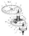
- the oscillating mass shown in Figure 1 in a position extreme and in Figure 2 in an equilibrium position, so includes known as an unbalance 31 having substantially the shape of a semicircle pivoted in its center on an axis 34 and integral with a toothed crown 32 which can come in one piece with the unbalance 31 or constitute a separate part, for example welded or force-fitted. Part of this ring gear 32 is not shown so as to make the device appear more clearly shockproof according to the invention housed in the intermediate mobile 20.
- the intermediate mobile 20 comprises a barrel 2 formed by a drum 27 closed on one side by a base 28 which extends radially beyond drum 27 to form a toothed wheel 21 whose teeth 22 mesh with the teeth 13 of the pinion 12 of the rotor.
- This intermediate mobile 20 is subsequently closed by a cover 30 shown partially torn off at Figure 2 to show the heart of the shockproof device.
- This cover 30 is positioned and fixed by means of pins 29 integral with the drum 27.
- the drum includes in its center a shaft 24 on which is blocked a ferrule 23 with four branches.
- This shaft 24 has one of its ends, on the side of the ferrule 23, mounted free to rotate in the base 28 and its other end is extended by a pinion 25 whose teeth 26 mesh with the teeth 33 of the ring gear 32 of the oscillating mass.
- a pinion 25 whose teeth 26 mesh with the teeth 33 of the ring gear 32 of the oscillating mass.
- the barrel includes a spiral spring 4 and a sliding blade 6 whose arrangement is explained below.
- the spiral spring 4 formed from 4 to 10 turns, has its end in the center secured to a branch of the shell 23 at a point 5.
- This connection is carried out in a known manner, by laser welding or by gluing.
- the end outside of the spiral spring 4 is secured at a point 9, visible in particular in FIG. 2, of the internal wall of the drum 27.
- this connection is made by welding the end of the spring in the substantially middle part of a metal plate 19 which is engaged in the grooves 18 of a housing provided in the drum 27.
- the spiral spring is formed by a blade whose section and the material which composes it are such that in normal operation, starting from the neutral position, represented in FIGS. 2 and 3B, in which the turns are regularly spaced, the turns begin to wind or unwind, then drive the barrel 2 to transmit the movement to the generator 1.
- the torque must be substantially between 5 ⁇ N.m.rad -1 and 500 ⁇ N.m.rad -1 .
- a steel spring can be used with a cross section of 0.04 x 0.5 mm.
- FIGS. 1 and 3A we have represented an extreme position in the event of a shock in which the turns of the spiral spring 4 are pressed against the wall of the drum 27 when the shaft 24 is driven clockwise (indicated by an arrow in Figure 3A).
- the attachment point 5 on the ferrule 23 can be torn off, or the first turn can be buckled, as shown by arrow 17 in FIG. 4.
- a sliding blade 6 is added which wraps the spiral spring 4 over a length substantially equal to the first turn of spring 4 in the open position ( Figure 3A), but without having no mechanical connection with it.
- This sliding blade 6 can have the same characteristics of elasticity than the spiral spring 4, or higher characteristics in acting either on its section or on the material that composes it.
- the blade 6 has one of its ends anchored on another branch of the ferrule 23 at a point 7, located upstream of the anchoring point 5 of the spring hairspring 4.
- the two anchor points have a 180 ° angular offset, but it is obvious that any other offset is possible, without departing from the scope of the invention.
- Figure 5 another type of ferrule with three branches which provides an angular offset of 120 °.
- the other end of the blade 6 is free and comes, in the open position ( Figure 3A), to pinch at a point 8 between the first and second turns of the spiral spring 4. This point 8 constitutes a temporary fulcrum which strengthens the first turn, i.e.
- the device which has just been described, with an intermediate mobile has the advantages of reducing the height of the entire device and to increase, by the play of gears which can have a multiplying factor of the order of 50, the rotational speed of the rotor and therefore having a favorable effect on the overall energy balance.
- the barrel 2 and the oscillating mass 3 can form a single mechanical unit.
- the unbalance 31 is then free to rotate relative to the ring gear 32, the axis 34 of the oscillating mass 3 coincides with the shaft 24 of the barrel 2 which then no longer has a pinion 25 and the drum 27 is integral with the ring gear 32 which performs the same functions as the toothed wheel 21 which can then be deleted. Expressed in another way the toothed crown 32 and the toothed wheel 21 are then merged.
- shockproof device to any type of wristwatch, or other non-horological products, such as cell phone to increase its operating autonomy.
Landscapes
- Engineering & Computer Science (AREA)
- Physics & Mathematics (AREA)
- General Physics & Mathematics (AREA)
- General Engineering & Computer Science (AREA)
- Power Engineering (AREA)
- Mechanical Engineering (AREA)
- Connection Of Motors, Electrical Generators, Mechanical Devices, And The Like (AREA)
- Electromechanical Clocks (AREA)
- Apparatuses For Generation Of Mechanical Vibrations (AREA)
- Vibration Dampers (AREA)
- Surgical Instruments (AREA)
Abstract
Description
- la figure 1 est une vue de dessus d'une génératrice incorporant le dispositif antichoc selon l'invention lorsque la masse oscillante occupe une position extrême;
- la figure 2 est une vue en perspective correspondant à la figure 1, mais limitée à la chaíne cinématique lorsque la masse oscillante est en position neutre;
- les figures 3A, 3B, 3C sont des vues de dessus du dispositif antichoc dans trois positions;
- la figure 4 est une représentation d'une déformation qui pourrait être observée en absence de dispositif antichoc selon l'invention; et
- la figure 5 est une variante du moyen de liaison au centre du dispositif antichoc.
Claims (8)
- Dispositif antichoc pour une génératrice (1) actionnée par les mouvements alternatifs d'une masse oscillante (3) transmis à la génératrice par l'intermédiaire d'un barillet (2), ladite génératrice (1) comprenant un rotor (11) pourvu d'un pignon (12), ladite masse oscillante (3) comprenant un balourd (31) solidaire d'un axe (34) et supporté par une couronne dentée (32), et ledit barillet (2) comprenant un tambour (27), ayant une base (28) prolongée radialement par une couronne pour former une roue dentée (21), libre en rotation autour d'un arbre pivoté (24) et à l'intérieur duquel est enroulé un ressort spiral (4) couplé par une extrémité à l'axe (34) de la masse oscillante (3) et fixé par l'autre extrémité à la paroi interne du tambour (27) pour former un moyen d'entraínement du rotor (11), ledit ressort spiral (4) ayant une constante d'élasticité telle qu'en fonctionnement normal les spires s'enroulent ou se déroulent à partir d'une position neutre dans laquelle elle sont régulièrement espacées et occupent en cas de choc une position ouverte dans laquelle les spires sont plaquées contre l'intérieur du tambour (27) ou une position fermée dans laquelle les spires sont regroupées au centre, caractérisé en ce qu'une lame glissante (6) est également couplée à l'arbre (24) entraíné par la masse oscillante (3), enroulé dans le même sens que le ressort spiral (4) et enveloppant ce dernier sans liaison mécanique rigide sur une longueur correspondant sensiblement à une spire en position ouverte.
- Dispositif antichoc pour génératrice selon la revendication 1, caractérisé en ce que le barillet (2) et la masse oscillante (3), dont le balourd (31) est monté libre à rotation par rapport à la couronne dentée (32), constituent une seule entité mécanique en ayant, d'une part leur arbre (24) et leur axe (34) respectifs confondus, d'autre part leur roue dentée (21) et leur couronne dentée (32) respectives confondues pour engrener directement avec le pignon (12) du rotor (11).
- Dispositif antichoc pour génératrice selon la revendication 1, caractérisé en ce que le barillet (2) forme un mobile intermédiaire (20) indépendant dont la roue dentée (21) engrène avec le pignon (12) du rotor (11) et dont l'arbre (24) est prolongé par un pignon (25) pour engrener avec la couronne dentée (32) rendue solidaire du balourd (31) de la masse oscillante (3).
- Dispositif antichoc pour génératrice selon la revendication 1, caractérisé en ce que les fixations du ressort spiral (4) et de la lame glissante (6) au centre sont effectuée par l'intermédiaire d'une virole (23) chassée sur l'arbre (24) du barillet (2) en permettant d'écarter les points de fixation respectifs (5, 7) d'un angle compris entre 30° et 180°.
- Dispositif antichoc pour génératrice selon la revendication 2, caractérisé en ce que le barillet (2) est obturé par un couvercle (30) maintenu par des goupilles (29) solidaires du tambour (27).
- Montre-bracelet comportant un dispositif antichoc pour génératrice selon une quelconque des revendications 1 à 5, pour alimenter un mouvement électronique et/ou une unité électronique associée à des moyens de réception et/ou émissions de signaux électromagnétiques.
- Dispositif antichoc pour génératrice selon la revendication 6, caractérisé en ce que la position neutre est obtenue en choisissant un ressort spiral (4) ayant une constante d'élasticité comprise entre 5 µN.m.rad-1 et 500 µN.m.rad-1.
- Dispositif antichoc par génératrice selon la revendication 1 caractérisé en ce que la lame glissante (6) a une constante d'élasticité supérieure à celle du ressort spiral (4) en ayant une section plus importante ou en ayant la même section mais en étant réalisé dans un matériau ayant lui même une constante supérieure.
Priority Applications (7)
| Application Number | Priority Date | Filing Date | Title |
|---|---|---|---|
| AT99118465T ATE421717T1 (de) | 1999-09-17 | 1999-09-17 | Stossfeste vorrichtung für einen durch eine schwungmasse angetriebenen generator |
| DE69940344T DE69940344D1 (de) | 1999-09-17 | 1999-09-17 | Stossfeste Vorrichtung für einen durch eine Schwungmasse angetriebenen Generator |
| EP99118465A EP1085383B1 (fr) | 1999-09-17 | 1999-09-17 | Dispositif antichoc pour générateur de puissance à masse oscillante |
| US09/661,550 US6441516B1 (en) | 1999-09-17 | 2000-09-14 | Shockproof device for a power generator with an oscillating weight |
| CNB001287478A CN1162760C (zh) | 1999-09-17 | 2000-09-15 | 用于一带摆动锤的发电器的防震装置 |
| JP2000281291A JP4426078B2 (ja) | 1999-09-17 | 2000-09-18 | 振動おもりを備える発電器のための耐衝撃装置 |
| HK01106602.6A HK1035937B (en) | 1999-09-17 | 2001-09-18 | Shockproof device for a power generator with an oscillating weight |
Applications Claiming Priority (1)
| Application Number | Priority Date | Filing Date | Title |
|---|---|---|---|
| EP99118465A EP1085383B1 (fr) | 1999-09-17 | 1999-09-17 | Dispositif antichoc pour générateur de puissance à masse oscillante |
Publications (2)
| Publication Number | Publication Date |
|---|---|
| EP1085383A1 true EP1085383A1 (fr) | 2001-03-21 |
| EP1085383B1 EP1085383B1 (fr) | 2009-01-21 |
Family
ID=8239017
Family Applications (1)
| Application Number | Title | Priority Date | Filing Date |
|---|---|---|---|
| EP99118465A Expired - Lifetime EP1085383B1 (fr) | 1999-09-17 | 1999-09-17 | Dispositif antichoc pour générateur de puissance à masse oscillante |
Country Status (6)
| Country | Link |
|---|---|
| US (1) | US6441516B1 (fr) |
| EP (1) | EP1085383B1 (fr) |
| JP (1) | JP4426078B2 (fr) |
| CN (1) | CN1162760C (fr) |
| AT (1) | ATE421717T1 (fr) |
| DE (1) | DE69940344D1 (fr) |
Cited By (6)
| Publication number | Priority date | Publication date | Assignee | Title |
|---|---|---|---|---|
| NL1017551C2 (nl) * | 2001-03-09 | 2002-09-10 | Kinetron Bv | Elektrisch voedingsspanningssysteem voor het omzetten van kinetische energie in elektrische energie ten behoeve van miniatuurinrichtingen. |
| EP1936787A1 (fr) * | 2006-12-21 | 2008-06-25 | Saab Ab | Dispositif ampg de génération d'énergie électrique à partir de vibrations, assemblage d'un dispositif ampg, et procédé pour optimiser la génération de cette énergie électrique |
| WO2012135887A3 (fr) * | 2011-04-04 | 2012-12-06 | Moshashvili Pinhas Roland | Dispositif de charge |
| DE102011106785A1 (de) | 2011-07-06 | 2013-01-10 | JuB-Creative Product GmbH | Kinetischer Wandler |
| EP3944027A1 (fr) | 2020-07-21 | 2022-01-26 | The Swatch Group Research and Development Ltd | Objet portable, notamment montre bracelet, comprenant un dispositif d'alimentation muni d'un convertisseur electromecanique |
| EP4215999A1 (fr) * | 2022-01-24 | 2023-07-26 | Flexous Mechanisms IP B.V. | Collecteur d'énergie pour un dispositif vestimentaire et/ou portatif |
Families Citing this family (25)
| Publication number | Priority date | Publication date | Assignee | Title |
|---|---|---|---|---|
| EP1077395B1 (fr) * | 1999-03-08 | 2009-06-24 | Seiko Epson Corporation | Dispositif d'enclenchement pour convertisseur electromagnetique, et dispositif horloge |
| JP2004170270A (ja) * | 2002-11-20 | 2004-06-17 | Seiko Instruments Inc | 規正装置を備えた自動巻時計 |
| GB2411708A (en) * | 2004-03-06 | 2005-09-07 | Arvinmeritor Light Vehicle Sys | An actuator assembly for use in conjunction with a latch assembly |
| ATE421720T1 (de) * | 2004-04-06 | 2009-02-15 | Nivarox Sa | Spiralrolle ohne deformation des fixierungsradius der spiralfeder und herstellungsverfahren derartige spiralrolle |
| EP1821163A3 (fr) * | 2006-02-13 | 2012-06-13 | Ventura Watch SA | Montre avec génératarice |
| EP2110719B1 (fr) * | 2008-04-15 | 2012-02-01 | Montres Jaquet Droz SA | Amortisseur de choc pour masse oscillante |
| US20100117462A1 (en) * | 2008-11-12 | 2010-05-13 | June-Chi Wang | Damper Power-Generating System |
| US8461730B2 (en) * | 2010-05-12 | 2013-06-11 | Science Applications International Corporation | Radial flux permanent magnet alternator with dielectric stator block |
| US9051918B1 (en) | 2011-02-25 | 2015-06-09 | Leidos, Inc. | Vertical axis wind turbine with tensile support structure having rigid or collapsible vanes |
| DE102011013873A1 (de) | 2011-03-15 | 2012-09-20 | Rainer Schmidt | Elektronische Schwungmasse |
| US9133815B1 (en) | 2011-05-11 | 2015-09-15 | Leidos, Inc. | Propeller-type double helix turbine apparatus and method |
| US8866328B1 (en) | 2011-06-07 | 2014-10-21 | Leidos, Inc. | System and method for generated power from wave action |
| US9331535B1 (en) | 2012-03-08 | 2016-05-03 | Leidos, Inc. | Radial flux alternator |
| JP6005504B2 (ja) * | 2012-12-25 | 2016-10-12 | 東洋ゴム工業株式会社 | 発電ユニット |
| EP2765462B1 (fr) * | 2013-02-12 | 2018-04-04 | ETA SA Manufacture Horlogère Suisse | Roue de centre anti-choc |
| CH710188A2 (fr) * | 2014-09-26 | 2016-03-31 | Eta Sa Manufacture Horlogère Suisse | Résonateur d'horlogerie paraxial et isochrone. |
| CN104898408A (zh) * | 2015-06-19 | 2015-09-09 | 四川分享微联科技有限公司 | 一种具有照明功能的手表结构 |
| TWI612761B (zh) * | 2016-08-15 | 2018-01-21 | 啓碁科技股份有限公司 | 微型發電機 |
| CN107957670B (zh) * | 2017-10-13 | 2020-03-24 | 烟台职业学院 | 一种大型机械表的智能上条机构 |
| NL2021361B1 (en) * | 2018-07-20 | 2020-01-29 | Kinetron Bv | Electric low-power supply system for devices and device comprising such a low-power supply system |
| CN109396956B (zh) * | 2018-11-06 | 2020-04-07 | 重庆大学 | 一种数控滚齿机滚刀状态智能监测方法 |
| CN109520687B (zh) * | 2018-12-29 | 2024-08-20 | 深圳市优必选科技有限公司 | 平面弹簧检测装置及平面弹簧检测方法 |
| CN110912338B (zh) * | 2019-12-04 | 2020-11-17 | 武汉久久智造科技有限公司 | 一种摇摆驱动装置 |
| DE102021111366A1 (de) | 2021-05-03 | 2022-11-03 | Technische Universität Chemnitz - Körperschaft des öffentlichen Rechts | Vorrichtung zur Erzeugung elektrischer Energie in einem Energiewandler |
| EP4303667B1 (fr) * | 2022-07-06 | 2025-08-27 | The Swatch Group Research and Development Ltd | Dispositif de génération d'énergie électrique pour pièce d'horlogerie |
Citations (5)
| Publication number | Priority date | Publication date | Assignee | Title |
|---|---|---|---|---|
| CH254577A (fr) | 1945-11-29 | 1948-05-15 | Longines Montres Comp D | Procédé pour amortir au moins les chocs latéraux s'exerçant sur les pivots de la masse oscillante d'une montre à remontage automatique et dispositif pour la mise en oeuvre de ce procédé. |
| CH281490A (fr) | 1950-03-06 | 1952-03-15 | Movado Montres | Pièce d'horlogerie à remontage automatique par masse oscillante. |
| FR1185795A (fr) | 1956-11-08 | 1959-08-05 | Babcock & Wilcox France | Chaudière à circulation forcée chauffée au charbon pulvérisé |
| EP0791867A1 (fr) | 1995-09-13 | 1997-08-27 | Citizen Watch Co. Ltd. | Petit appareil electronique equipe d'un generateur |
| EP0918265A1 (fr) * | 1997-11-24 | 1999-05-26 | Eta SA Fabriques d'Ebauches | Dispositif d'entraínement d'un générateur pour instrument de petit volume |
Family Cites Families (8)
| Publication number | Priority date | Publication date | Assignee | Title |
|---|---|---|---|---|
| US1276456A (en) * | 1918-08-20 | Otto Heineman Phonograph Supply Co Inc | Fastening device. | |
| US2399131A (en) * | 1942-07-09 | 1946-04-23 | Michel S A Grenchen A | Automatic winding mechanism for timepieces |
| US2721627A (en) * | 1952-02-01 | 1955-10-25 | Eastman Kodak Co | Shock-absorber for spring motors |
| CH552843A (fr) * | 1971-07-22 | 1974-08-15 | ||
| NL9001976A (nl) * | 1990-09-07 | 1992-04-01 | Kinetron Bv | Generator. |
| CH686474B5 (fr) * | 1994-05-04 | 1996-10-15 | Ebauchesfabrik Eta Ag | Dispositif de couplage entre une source d'énergie mécanique et une génératrice électrique dans une pièce d'horlogerie. |
| JP3472877B2 (ja) * | 1997-09-30 | 2003-12-02 | セイコーエプソン株式会社 | 電子制御式機械時計およびその制御方法 |
| CH696507A5 (fr) * | 1998-02-05 | 2007-07-13 | Asulab Sa | Pièce d'horlogerie électronique comportant une génératrice entraînée par un barillet à ressort. |
-
1999
- 1999-09-17 DE DE69940344T patent/DE69940344D1/de not_active Expired - Lifetime
- 1999-09-17 EP EP99118465A patent/EP1085383B1/fr not_active Expired - Lifetime
- 1999-09-17 AT AT99118465T patent/ATE421717T1/de not_active IP Right Cessation
-
2000
- 2000-09-14 US US09/661,550 patent/US6441516B1/en not_active Expired - Lifetime
- 2000-09-15 CN CNB001287478A patent/CN1162760C/zh not_active Expired - Lifetime
- 2000-09-18 JP JP2000281291A patent/JP4426078B2/ja not_active Expired - Lifetime
Patent Citations (5)
| Publication number | Priority date | Publication date | Assignee | Title |
|---|---|---|---|---|
| CH254577A (fr) | 1945-11-29 | 1948-05-15 | Longines Montres Comp D | Procédé pour amortir au moins les chocs latéraux s'exerçant sur les pivots de la masse oscillante d'une montre à remontage automatique et dispositif pour la mise en oeuvre de ce procédé. |
| CH281490A (fr) | 1950-03-06 | 1952-03-15 | Movado Montres | Pièce d'horlogerie à remontage automatique par masse oscillante. |
| FR1185795A (fr) | 1956-11-08 | 1959-08-05 | Babcock & Wilcox France | Chaudière à circulation forcée chauffée au charbon pulvérisé |
| EP0791867A1 (fr) | 1995-09-13 | 1997-08-27 | Citizen Watch Co. Ltd. | Petit appareil electronique equipe d'un generateur |
| EP0918265A1 (fr) * | 1997-11-24 | 1999-05-26 | Eta SA Fabriques d'Ebauches | Dispositif d'entraínement d'un générateur pour instrument de petit volume |
Cited By (11)
| Publication number | Priority date | Publication date | Assignee | Title |
|---|---|---|---|---|
| NL1017551C2 (nl) * | 2001-03-09 | 2002-09-10 | Kinetron Bv | Elektrisch voedingsspanningssysteem voor het omzetten van kinetische energie in elektrische energie ten behoeve van miniatuurinrichtingen. |
| EP1239349A1 (fr) * | 2001-03-09 | 2002-09-11 | Kinetron B.V. | Appareil d'alimentation de puissance pour la conversion d'énergie mécanique en énergie électrique utilisable dans des dispositifs miniatures |
| EP1936787A1 (fr) * | 2006-12-21 | 2008-06-25 | Saab Ab | Dispositif ampg de génération d'énergie électrique à partir de vibrations, assemblage d'un dispositif ampg, et procédé pour optimiser la génération de cette énergie électrique |
| US8304937B2 (en) | 2006-12-21 | 2012-11-06 | Saab Ab | AMPG device for generation of electrical energy from vibrations, an AMPG device assemby, and a method to optimize the generation of said electrical energy |
| WO2012135887A3 (fr) * | 2011-04-04 | 2012-12-06 | Moshashvili Pinhas Roland | Dispositif de charge |
| DE102011106785A1 (de) | 2011-07-06 | 2013-01-10 | JuB-Creative Product GmbH | Kinetischer Wandler |
| DE102011106785B4 (de) * | 2011-07-06 | 2015-07-23 | JuB-Creative Product GmbH | Kinetischer Wandler |
| EP3944027A1 (fr) | 2020-07-21 | 2022-01-26 | The Swatch Group Research and Development Ltd | Objet portable, notamment montre bracelet, comprenant un dispositif d'alimentation muni d'un convertisseur electromecanique |
| US20220026854A1 (en) * | 2020-07-21 | 2022-01-27 | The Swatch Group Research And Development Ltd | Wearable object, in particular watch bracelet, comprising a power supply device provided with an electromechanical converter |
| US12169391B2 (en) * | 2020-07-21 | 2024-12-17 | The Swatch Group Research And Development Ltd | Wearable object, in particular watch bracelet, comprising a power supply device provided with an electromechanical converter |
| EP4215999A1 (fr) * | 2022-01-24 | 2023-07-26 | Flexous Mechanisms IP B.V. | Collecteur d'énergie pour un dispositif vestimentaire et/ou portatif |
Also Published As
| Publication number | Publication date |
|---|---|
| CN1289072A (zh) | 2001-03-28 |
| EP1085383B1 (fr) | 2009-01-21 |
| US6441516B1 (en) | 2002-08-27 |
| DE69940344D1 (de) | 2009-03-12 |
| CN1162760C (zh) | 2004-08-18 |
| ATE421717T1 (de) | 2009-02-15 |
| HK1035937A1 (en) | 2001-12-14 |
| JP4426078B2 (ja) | 2010-03-03 |
| JP2001141839A (ja) | 2001-05-25 |
Similar Documents
| Publication | Publication Date | Title |
|---|---|---|
| EP1085383B1 (fr) | Dispositif antichoc pour générateur de puissance à masse oscillante | |
| EP2166419B1 (fr) | Mouvement horloger comportant un dispositif à force constante | |
| EP2583143B1 (fr) | Mécanisme d'avance par saut périodique d'une cage de tourbillon ou d'une cage de carrousel | |
| EP2397921B1 (fr) | Mécanisme d'avance par saut périodique d'une cage de carrousel | |
| EP2871537A1 (fr) | Montre à réserve de marche améliorée | |
| EP4002016B1 (fr) | Montre a mouvement mecanique a mecanisme de controle de force | |
| EP3944027B1 (fr) | Objet portable, notamment montre bracelet, comprenant un dispositif d'alimentation muni d'un convertisseur electromecanique | |
| EP2313812B1 (fr) | Mouvement pour piece d'horlogerie a dispositif de remontage automatique embarque | |
| EP3306416B1 (fr) | Mouvement d'horlogerie mécanique à détection de réserve de marche | |
| EP1213626B1 (fr) | Dispositif de transmission antichoc pour l'entraînement d'une génératrice par une masse oscillante, notamment dans une montre | |
| CH692875A5 (fr) | Dispositif d'entraînement d'un générateur et instrument de petit volume muni d'un tel dispositif. | |
| CH686474B5 (fr) | Dispositif de couplage entre une source d'énergie mécanique et une génératrice électrique dans une pièce d'horlogerie. | |
| CH692874A5 (fr) | Instrument de petit volume muni d'un dispositif de limitation de la puissance mécanique fournie par une masse oscillante. | |
| CH700035B1 (fr) | Mouvement d'horlogerie muni d'un mécanisme d'embrayage inertiel. | |
| EP3547041B1 (fr) | Garde-temps comportant un oscillateur mecanique | |
| EP0924579B1 (fr) | Dispositif de limitation de la puissance fournie par une masse oscillante pour instruments de petit volume | |
| CH703331B1 (fr) | Mécanisme d'avance par saut périodique d'une cage de tourbillon ou d'une cage de carrousel. | |
| EP0918265B1 (fr) | Dispositif d'entraínement d'un générateur pour instrument de petit volume | |
| WO2006058925A2 (fr) | Piece d'horlogerie a animation | |
| EP4080292B1 (fr) | Mécanisme horloger d' affichage d' au moins l 'indication de l' heure unique et piece d' horlogerie comprenant un tel mécanisme | |
| CH715502B1 (fr) | Module horloger mécanique de comptage et d'affichage de l'activité physique d'un utilisateur. | |
| CH701968B1 (fr) | Source d'énergie pour sonnerie et pièce d'horlogerie munie d'une telle source d'énergie. | |
| EP2109015A2 (fr) | Mécanisme de remontoir automatique | |
| CH719508A9 (fr) | Mécanisme de force constante. | |
| CH714615B1 (fr) | Mécanisme de transmission d'une force d'armage, mouvement et pièce d'horlogerie mécanique. |
Legal Events
| Date | Code | Title | Description |
|---|---|---|---|
| PUAI | Public reference made under article 153(3) epc to a published international application that has entered the european phase |
Free format text: ORIGINAL CODE: 0009012 |
|
| AK | Designated contracting states |
Kind code of ref document: A1 Designated state(s): AT BE CH CY DE DK ES FI FR GB GR IE IT LI LU MC NL PT SE |
|
| AX | Request for extension of the european patent |
Free format text: AL;LT;LV;MK;RO;SI |
|
| 17P | Request for examination filed |
Effective date: 20010921 |
|
| AKX | Designation fees paid |
Free format text: AT BE CH CY DE DK ES FI FR GB GR IE IT LI LU MC NL PT SE |
|
| RAP1 | Party data changed (applicant data changed or rights of an application transferred) |
Owner name: ETA SA MANUFACTURE HORLOGERE SUISSE |
|
| GRAP | Despatch of communication of intention to grant a patent |
Free format text: ORIGINAL CODE: EPIDOSNIGR1 |
|
| GRAS | Grant fee paid |
Free format text: ORIGINAL CODE: EPIDOSNIGR3 |
|
| GRAA | (expected) grant |
Free format text: ORIGINAL CODE: 0009210 |
|
| AK | Designated contracting states |
Kind code of ref document: B1 Designated state(s): AT BE CH CY DE DK ES FI FR GB GR IE IT LI LU MC NL PT SE |
|
| REG | Reference to a national code |
Ref country code: GB Ref legal event code: FG4D Free format text: NOT ENGLISH |
|
| REG | Reference to a national code |
Ref country code: CH Ref legal event code: EP |
|
| REG | Reference to a national code |
Ref country code: IE Ref legal event code: FG4D Free format text: LANGUAGE OF EP DOCUMENT: FRENCH |
|
| REG | Reference to a national code |
Ref country code: CH Ref legal event code: NV Representative=s name: ICB INGENIEURS CONSEILS EN BREVETS SA |
|
| REF | Corresponds to: |
Ref document number: 69940344 Country of ref document: DE Date of ref document: 20090312 Kind code of ref document: P |
|
| PG25 | Lapsed in a contracting state [announced via postgrant information from national office to epo] |
Ref country code: NL Free format text: LAPSE BECAUSE OF FAILURE TO SUBMIT A TRANSLATION OF THE DESCRIPTION OR TO PAY THE FEE WITHIN THE PRESCRIBED TIME-LIMIT Effective date: 20090121 |
|
| NLV1 | Nl: lapsed or annulled due to failure to fulfill the requirements of art. 29p and 29m of the patents act | ||
| PG25 | Lapsed in a contracting state [announced via postgrant information from national office to epo] |
Ref country code: FI Free format text: LAPSE BECAUSE OF FAILURE TO SUBMIT A TRANSLATION OF THE DESCRIPTION OR TO PAY THE FEE WITHIN THE PRESCRIBED TIME-LIMIT Effective date: 20090121 Ref country code: ES Free format text: LAPSE BECAUSE OF FAILURE TO SUBMIT A TRANSLATION OF THE DESCRIPTION OR TO PAY THE FEE WITHIN THE PRESCRIBED TIME-LIMIT Effective date: 20090502 |
|
| REG | Reference to a national code |
Ref country code: IE Ref legal event code: FD4D |
|
| PG25 | Lapsed in a contracting state [announced via postgrant information from national office to epo] |
Ref country code: SE Free format text: LAPSE BECAUSE OF FAILURE TO SUBMIT A TRANSLATION OF THE DESCRIPTION OR TO PAY THE FEE WITHIN THE PRESCRIBED TIME-LIMIT Effective date: 20090421 Ref country code: PT Free format text: LAPSE BECAUSE OF FAILURE TO SUBMIT A TRANSLATION OF THE DESCRIPTION OR TO PAY THE FEE WITHIN THE PRESCRIBED TIME-LIMIT Effective date: 20090622 Ref country code: AT Free format text: LAPSE BECAUSE OF FAILURE TO SUBMIT A TRANSLATION OF THE DESCRIPTION OR TO PAY THE FEE WITHIN THE PRESCRIBED TIME-LIMIT Effective date: 20090121 |
|
| PG25 | Lapsed in a contracting state [announced via postgrant information from national office to epo] |
Ref country code: IE Free format text: LAPSE BECAUSE OF FAILURE TO SUBMIT A TRANSLATION OF THE DESCRIPTION OR TO PAY THE FEE WITHIN THE PRESCRIBED TIME-LIMIT Effective date: 20090121 Ref country code: DK Free format text: LAPSE BECAUSE OF FAILURE TO SUBMIT A TRANSLATION OF THE DESCRIPTION OR TO PAY THE FEE WITHIN THE PRESCRIBED TIME-LIMIT Effective date: 20090121 |
|
| PLBE | No opposition filed within time limit |
Free format text: ORIGINAL CODE: 0009261 |
|
| STAA | Information on the status of an ep patent application or granted ep patent |
Free format text: STATUS: NO OPPOSITION FILED WITHIN TIME LIMIT |
|
| 26N | No opposition filed |
Effective date: 20091022 |
|
| BERE | Be: lapsed |
Owner name: ETA SA MANUFACTURE HORLOGERE SUISSE Effective date: 20090930 |
|
| PG25 | Lapsed in a contracting state [announced via postgrant information from national office to epo] |
Ref country code: MC Free format text: LAPSE BECAUSE OF NON-PAYMENT OF DUE FEES Effective date: 20090930 |
|
| PG25 | Lapsed in a contracting state [announced via postgrant information from national office to epo] |
Ref country code: BE Free format text: LAPSE BECAUSE OF NON-PAYMENT OF DUE FEES Effective date: 20090930 |
|
| PG25 | Lapsed in a contracting state [announced via postgrant information from national office to epo] |
Ref country code: GR Free format text: LAPSE BECAUSE OF FAILURE TO SUBMIT A TRANSLATION OF THE DESCRIPTION OR TO PAY THE FEE WITHIN THE PRESCRIBED TIME-LIMIT Effective date: 20090422 |
|
| PG25 | Lapsed in a contracting state [announced via postgrant information from national office to epo] |
Ref country code: IT Free format text: LAPSE BECAUSE OF FAILURE TO SUBMIT A TRANSLATION OF THE DESCRIPTION OR TO PAY THE FEE WITHIN THE PRESCRIBED TIME-LIMIT Effective date: 20090121 |
|
| PG25 | Lapsed in a contracting state [announced via postgrant information from national office to epo] |
Ref country code: LU Free format text: LAPSE BECAUSE OF NON-PAYMENT OF DUE FEES Effective date: 20090917 |
|
| PG25 | Lapsed in a contracting state [announced via postgrant information from national office to epo] |
Ref country code: CY Free format text: LAPSE BECAUSE OF FAILURE TO SUBMIT A TRANSLATION OF THE DESCRIPTION OR TO PAY THE FEE WITHIN THE PRESCRIBED TIME-LIMIT Effective date: 20090121 |
|
| REG | Reference to a national code |
Ref country code: FR Ref legal event code: PLFP Year of fee payment: 17 |
|
| PGFP | Annual fee paid to national office [announced via postgrant information from national office to epo] |
Ref country code: GB Payment date: 20150825 Year of fee payment: 17 Ref country code: DE Payment date: 20150820 Year of fee payment: 17 |
|
| PGFP | Annual fee paid to national office [announced via postgrant information from national office to epo] |
Ref country code: FR Payment date: 20150824 Year of fee payment: 17 |
|
| REG | Reference to a national code |
Ref country code: DE Ref legal event code: R119 Ref document number: 69940344 Country of ref document: DE |
|
| GBPC | Gb: european patent ceased through non-payment of renewal fee |
Effective date: 20160917 |
|
| REG | Reference to a national code |
Ref country code: FR Ref legal event code: ST Effective date: 20170531 |
|
| PG25 | Lapsed in a contracting state [announced via postgrant information from national office to epo] |
Ref country code: GB Free format text: LAPSE BECAUSE OF NON-PAYMENT OF DUE FEES Effective date: 20160917 Ref country code: FR Free format text: LAPSE BECAUSE OF NON-PAYMENT OF DUE FEES Effective date: 20160930 Ref country code: DE Free format text: LAPSE BECAUSE OF NON-PAYMENT OF DUE FEES Effective date: 20170401 |
|
| PGFP | Annual fee paid to national office [announced via postgrant information from national office to epo] |
Ref country code: CH Payment date: 20180828 Year of fee payment: 20 |
|
| REG | Reference to a national code |
Ref country code: CH Ref legal event code: PL |