EP1085243B1 - Behälter zur Aufnahme eines unter Druck stehenden Mediums - Google Patents
Behälter zur Aufnahme eines unter Druck stehenden Mediums Download PDFInfo
- Publication number
- EP1085243B1 EP1085243B1 EP99118286A EP99118286A EP1085243B1 EP 1085243 B1 EP1085243 B1 EP 1085243B1 EP 99118286 A EP99118286 A EP 99118286A EP 99118286 A EP99118286 A EP 99118286A EP 1085243 B1 EP1085243 B1 EP 1085243B1
- Authority
- EP
- European Patent Office
- Prior art keywords
- container
- collar
- wall
- central section
- connection
- Prior art date
- Legal status (The legal status is an assumption and is not a legal conclusion. Google has not performed a legal analysis and makes no representation as to the accuracy of the status listed.)
- Expired - Lifetime
Links
- 239000002131 composite material Substances 0.000 claims abstract description 18
- 239000004033 plastic Substances 0.000 claims abstract description 13
- 229920003023 plastic Polymers 0.000 claims abstract description 13
- 239000000835 fiber Substances 0.000 claims description 27
- 238000007789 sealing Methods 0.000 claims description 12
- 229920001169 thermoplastic Polymers 0.000 claims description 8
- 239000004416 thermosoftening plastic Substances 0.000 claims description 7
- 238000001746 injection moulding Methods 0.000 claims description 6
- 230000006835 compression Effects 0.000 claims description 4
- 238000007906 compression Methods 0.000 claims description 4
- 238000003466 welding Methods 0.000 claims description 3
- 239000000853 adhesive Substances 0.000 claims 2
- 230000001070 adhesive effect Effects 0.000 claims 2
- 238000004026 adhesive bonding Methods 0.000 claims 1
- 230000000284 resting effect Effects 0.000 abstract 1
- 239000002689 soil Substances 0.000 description 18
- 230000008901 benefit Effects 0.000 description 10
- 239000010410 layer Substances 0.000 description 10
- 239000000463 material Substances 0.000 description 9
- 238000011161 development Methods 0.000 description 8
- 238000004519 manufacturing process Methods 0.000 description 8
- 230000035882 stress Effects 0.000 description 4
- 150000001875 compounds Chemical class 0.000 description 3
- 238000010276 construction Methods 0.000 description 3
- 239000004744 fabric Substances 0.000 description 3
- 239000011159 matrix material Substances 0.000 description 3
- 238000013461 design Methods 0.000 description 2
- 239000002184 metal Substances 0.000 description 2
- 229910052751 metal Inorganic materials 0.000 description 2
- 239000007769 metal material Substances 0.000 description 2
- 239000007787 solid Substances 0.000 description 2
- 238000012549 training Methods 0.000 description 2
- 238000004804 winding Methods 0.000 description 2
- 229920002430 Fibre-reinforced plastic Polymers 0.000 description 1
- 229910000831 Steel Inorganic materials 0.000 description 1
- 238000004873 anchoring Methods 0.000 description 1
- 238000013459 approach Methods 0.000 description 1
- 238000005452 bending Methods 0.000 description 1
- 230000000295 complement effect Effects 0.000 description 1
- 238000005336 cracking Methods 0.000 description 1
- 238000009792 diffusion process Methods 0.000 description 1
- 230000002349 favourable effect Effects 0.000 description 1
- 239000011151 fibre-reinforced plastic Substances 0.000 description 1
- 239000006260 foam Substances 0.000 description 1
- 238000002347 injection Methods 0.000 description 1
- 239000007924 injection Substances 0.000 description 1
- 238000007689 inspection Methods 0.000 description 1
- 230000010354 integration Effects 0.000 description 1
- 239000011229 interlayer Substances 0.000 description 1
- 239000007788 liquid Substances 0.000 description 1
- 238000002844 melting Methods 0.000 description 1
- 230000008018 melting Effects 0.000 description 1
- 239000012528 membrane Substances 0.000 description 1
- 150000002739 metals Chemical class 0.000 description 1
- 239000012778 molding material Substances 0.000 description 1
- 230000002093 peripheral effect Effects 0.000 description 1
- 238000003825 pressing Methods 0.000 description 1
- 238000004064 recycling Methods 0.000 description 1
- 230000002787 reinforcement Effects 0.000 description 1
- 239000012783 reinforcing fiber Substances 0.000 description 1
- 238000000926 separation method Methods 0.000 description 1
- 239000010959 steel Substances 0.000 description 1
- 230000008646 thermal stress Effects 0.000 description 1
- 239000012815 thermoplastic material Substances 0.000 description 1
- 230000007704 transition Effects 0.000 description 1
Images



Classifications
-
- F—MECHANICAL ENGINEERING; LIGHTING; HEATING; WEAPONS; BLASTING
- F17—STORING OR DISTRIBUTING GASES OR LIQUIDS
- F17C—VESSELS FOR CONTAINING OR STORING COMPRESSED, LIQUEFIED OR SOLIDIFIED GASES; FIXED-CAPACITY GAS-HOLDERS; FILLING VESSELS WITH, OR DISCHARGING FROM VESSELS, COMPRESSED, LIQUEFIED, OR SOLIDIFIED GASES
- F17C1/00—Pressure vessels, e.g. gas cylinder, gas tank, replaceable cartridge
- F17C1/16—Pressure vessels, e.g. gas cylinder, gas tank, replaceable cartridge constructed of plastics materials
-
- F—MECHANICAL ENGINEERING; LIGHTING; HEATING; WEAPONS; BLASTING
- F16—ENGINEERING ELEMENTS AND UNITS; GENERAL MEASURES FOR PRODUCING AND MAINTAINING EFFECTIVE FUNCTIONING OF MACHINES OR INSTALLATIONS; THERMAL INSULATION IN GENERAL
- F16J—PISTONS; CYLINDERS; SEALINGS
- F16J12/00—Pressure vessels in general
-
- F—MECHANICAL ENGINEERING; LIGHTING; HEATING; WEAPONS; BLASTING
- F17—STORING OR DISTRIBUTING GASES OR LIQUIDS
- F17C—VESSELS FOR CONTAINING OR STORING COMPRESSED, LIQUEFIED OR SOLIDIFIED GASES; FIXED-CAPACITY GAS-HOLDERS; FILLING VESSELS WITH, OR DISCHARGING FROM VESSELS, COMPRESSED, LIQUEFIED, OR SOLIDIFIED GASES
- F17C2201/00—Vessel construction, in particular geometry, arrangement or size
- F17C2201/01—Shape
- F17C2201/0104—Shape cylindrical
- F17C2201/0114—Shape cylindrical with interiorly curved end-piece
-
- F—MECHANICAL ENGINEERING; LIGHTING; HEATING; WEAPONS; BLASTING
- F17—STORING OR DISTRIBUTING GASES OR LIQUIDS
- F17C—VESSELS FOR CONTAINING OR STORING COMPRESSED, LIQUEFIED OR SOLIDIFIED GASES; FIXED-CAPACITY GAS-HOLDERS; FILLING VESSELS WITH, OR DISCHARGING FROM VESSELS, COMPRESSED, LIQUEFIED, OR SOLIDIFIED GASES
- F17C2203/00—Vessel construction, in particular walls or details thereof
- F17C2203/06—Materials for walls or layers thereof; Properties or structures of walls or their materials
- F17C2203/0634—Materials for walls or layers thereof
- F17C2203/0658—Synthetics
- F17C2203/0663—Synthetics in form of fibers or filaments
-
- F—MECHANICAL ENGINEERING; LIGHTING; HEATING; WEAPONS; BLASTING
- F17—STORING OR DISTRIBUTING GASES OR LIQUIDS
- F17C—VESSELS FOR CONTAINING OR STORING COMPRESSED, LIQUEFIED OR SOLIDIFIED GASES; FIXED-CAPACITY GAS-HOLDERS; FILLING VESSELS WITH, OR DISCHARGING FROM VESSELS, COMPRESSED, LIQUEFIED, OR SOLIDIFIED GASES
- F17C2205/00—Vessel construction, in particular mounting arrangements, attachments or identifications means
- F17C2205/01—Mounting arrangements
- F17C2205/0153—Details of mounting arrangements
- F17C2205/018—Supporting feet
-
- F—MECHANICAL ENGINEERING; LIGHTING; HEATING; WEAPONS; BLASTING
- F17—STORING OR DISTRIBUTING GASES OR LIQUIDS
- F17C—VESSELS FOR CONTAINING OR STORING COMPRESSED, LIQUEFIED OR SOLIDIFIED GASES; FIXED-CAPACITY GAS-HOLDERS; FILLING VESSELS WITH, OR DISCHARGING FROM VESSELS, COMPRESSED, LIQUEFIED, OR SOLIDIFIED GASES
- F17C2209/00—Vessel construction, in particular methods of manufacturing
- F17C2209/21—Shaping processes
- F17C2209/2109—Moulding
-
- F—MECHANICAL ENGINEERING; LIGHTING; HEATING; WEAPONS; BLASTING
- F17—STORING OR DISTRIBUTING GASES OR LIQUIDS
- F17C—VESSELS FOR CONTAINING OR STORING COMPRESSED, LIQUEFIED OR SOLIDIFIED GASES; FIXED-CAPACITY GAS-HOLDERS; FILLING VESSELS WITH, OR DISCHARGING FROM VESSELS, COMPRESSED, LIQUEFIED, OR SOLIDIFIED GASES
- F17C2209/00—Vessel construction, in particular methods of manufacturing
- F17C2209/22—Assembling processes
- F17C2209/221—Welding
-
- F—MECHANICAL ENGINEERING; LIGHTING; HEATING; WEAPONS; BLASTING
- F17—STORING OR DISTRIBUTING GASES OR LIQUIDS
- F17C—VESSELS FOR CONTAINING OR STORING COMPRESSED, LIQUEFIED OR SOLIDIFIED GASES; FIXED-CAPACITY GAS-HOLDERS; FILLING VESSELS WITH, OR DISCHARGING FROM VESSELS, COMPRESSED, LIQUEFIED, OR SOLIDIFIED GASES
- F17C2209/00—Vessel construction, in particular methods of manufacturing
- F17C2209/22—Assembling processes
- F17C2209/227—Assembling processes by adhesive means
-
- F—MECHANICAL ENGINEERING; LIGHTING; HEATING; WEAPONS; BLASTING
- F17—STORING OR DISTRIBUTING GASES OR LIQUIDS
- F17C—VESSELS FOR CONTAINING OR STORING COMPRESSED, LIQUEFIED OR SOLIDIFIED GASES; FIXED-CAPACITY GAS-HOLDERS; FILLING VESSELS WITH, OR DISCHARGING FROM VESSELS, COMPRESSED, LIQUEFIED, OR SOLIDIFIED GASES
- F17C2209/00—Vessel construction, in particular methods of manufacturing
- F17C2209/22—Assembling processes
- F17C2209/228—Assembling processes by screws, bolts or rivets
-
- F—MECHANICAL ENGINEERING; LIGHTING; HEATING; WEAPONS; BLASTING
- F17—STORING OR DISTRIBUTING GASES OR LIQUIDS
- F17C—VESSELS FOR CONTAINING OR STORING COMPRESSED, LIQUEFIED OR SOLIDIFIED GASES; FIXED-CAPACITY GAS-HOLDERS; FILLING VESSELS WITH, OR DISCHARGING FROM VESSELS, COMPRESSED, LIQUEFIED, OR SOLIDIFIED GASES
- F17C2223/00—Handled fluid before transfer, i.e. state of fluid when stored in the vessel or before transfer from the vessel
- F17C2223/03—Handled fluid before transfer, i.e. state of fluid when stored in the vessel or before transfer from the vessel characterised by the pressure level
- F17C2223/035—High pressure (>10 bar)
-
- F—MECHANICAL ENGINEERING; LIGHTING; HEATING; WEAPONS; BLASTING
- F17—STORING OR DISTRIBUTING GASES OR LIQUIDS
- F17C—VESSELS FOR CONTAINING OR STORING COMPRESSED, LIQUEFIED OR SOLIDIFIED GASES; FIXED-CAPACITY GAS-HOLDERS; FILLING VESSELS WITH, OR DISCHARGING FROM VESSELS, COMPRESSED, LIQUEFIED, OR SOLIDIFIED GASES
- F17C2223/00—Handled fluid before transfer, i.e. state of fluid when stored in the vessel or before transfer from the vessel
- F17C2223/03—Handled fluid before transfer, i.e. state of fluid when stored in the vessel or before transfer from the vessel characterised by the pressure level
- F17C2223/036—Very high pressure (>80 bar)
-
- F—MECHANICAL ENGINEERING; LIGHTING; HEATING; WEAPONS; BLASTING
- F17—STORING OR DISTRIBUTING GASES OR LIQUIDS
- F17C—VESSELS FOR CONTAINING OR STORING COMPRESSED, LIQUEFIED OR SOLIDIFIED GASES; FIXED-CAPACITY GAS-HOLDERS; FILLING VESSELS WITH, OR DISCHARGING FROM VESSELS, COMPRESSED, LIQUEFIED, OR SOLIDIFIED GASES
- F17C2260/00—Purposes of gas storage and gas handling
- F17C2260/03—Dealing with losses
- F17C2260/035—Dealing with losses of fluid
- F17C2260/036—Avoiding leaks
Definitions
- the invention relates to a container for receiving a pressurized standing medium, which consists essentially of a fiber-plastic composite material is made, the shape of a tubular Middle part consists, at the ends to the closure of the container in each case a bottom is formed.
- a container according to the Preamble of claim 1 is z. B. from DE-A-3 922 577 known.
- the invention is based on a container for receiving an under Pressurized medium made from a fiber-plastic composite is because fiber-plastic composites offer over The metallic materials in particular the advantage of great weight savings.
- the high fiber strength can be optimal be used because the lightweight construction by the ratio tensile strength / density and this in fiber-plastic composites is very high compared to metallic materials.
- a sealing layer built into the container interior is known as a liner
- a liner can cause a large-scale container failure be prevented.
- the reason for this is that already well before the fiber strength is reached, so-called intermediate fiber breaks may occur. These run parallel to the fibers in The matrix and are mainly by voltages transverse to the fiber direction. thus generated by Queryak.
- the consequence of such a container failure would be that the liquid emerges droplet-shaped and one speaks of "Weeping".
- the floor area is in the transition area Cylinder endangered to the ground, where in particular additional moments from the different deformation behavior of the two Shells result. Weeping is the most common here on.
- the liner has the inside dimensions of the container and serves at the same time also as a winding core on which the reinforcing fibers are defined below Angles are stored.
- a liner By using a liner one bypasses also advantageous the problem of the winding core after container production to have to remove from the interior again.
- Liner material Metals or plastics are used.
- the liner also has serious disadvantages, which arise from the use of a liner and consist in that if the liner is not permanently stuck with the load-bearing laminate layer connected during operation - e.g. as a result the different thermal expansions of laminate and unreinforced Liner - on the one hand to high thermal stresses and on the other hand to Deformation of the liner come with stability failure.
- the stored by diffusion Medium passes between liner and base layer, causing the liner on External pressure loaded and thus also endangered stability.
- a compound laminate and liner helps by melting fabric into the liner surface, all the more so at least one mechanical anchoring with the load-bearing laminate layer to achieve.
- the separate Partly trained floor made of a fiber-plastic composite material consists of short, long or continuous fibers, is formed curved inside in the container space.
- the arrangement of the soil in the manner of the invention brings in essentially the advantage. that instead of the dangerous tensile stresses, which occur especially in the outer curvature, now due the reversal of the soil in the surface area transverse compressive stresses occur. Because the transverse compressive strength of unidirectional laminate layers but about three times as high as the transverse tensile strength, can the container with inwardly curved floors about three times load higher before Weeping occurs. This is different Approach, as the case of metallic containers, where the desire for Adjustable to domed floors has led.
- a fiber composite at the inside curvature raises the cracking limits clearly and prevents early leakage. Consciously it is accepted taken that the fibers parallel to the fiber direction unfavorably be charged to pressure; however, the benefits of the overpressure load outweigh the benefits on the Weeping borders. Another advantage results in the inwardly arched soil training from the fact that Adjustability of the container is possible, taking the opportunity results in producing infinite container volumes. According to the invention So it has been possible, a higher load capacity internal pressure vessel Made of fiber-plastic composite material due to the clever use of the more favorable material strengths also particularly large weight savings compared to all previous ones Allow constructions. Also in the production of such container according to the invention, there are advantages to see therein are.
- the container production is no longer one piece, but the cylindrical container area, for example, as one piece Tube is made on a steel core and then, after peeling off the core, the middle part can be cut to length. In this way can be without additional tooling any length of container, i. any volume, set.
- the inwardly curved bottom a circumferential collar is arranged, which rests against the inner wall of the central part and connected thereto is.
- the floor can be glued in thermoplastic Matrix systems are also welded.
- a bolt connection so e.g. through rivets or to connect screws with the cylinder part.
- a positive connection which arises because after the Inserting the bottom into the container cylinder area a support ring is pressed over the ends of the cylinder area, causing the soil secured against expulsion by internal pressure.
- a special advantageous development is the conical bottom at the ends to design.
- the floors with the middle part it is proposed to use friction-enhancing interlayers, a screw connection or snap closures for connection of the soil in the region of the collar.
- this one additional sealing function In addition to the improvement of the connection one achieves this one additional sealing function.
- the fiber composite laminate be equipped with a thermoplastic matrix system can.
- the component can be ground and the fiber-reinforced laminate - depending on the fiber length - in mat-reinforced semi-finished or in short-fiber injection molding material incorporated and processed into new components. Therefore
- the soil not only as a fiber composite structure made with short or continuous fibers, especially from short fiber reinforced Thermoplastic plastic injection molding or pressing.
- the soil structure should be not be executed as a solid cross section, but ribbed. Into the nodes of the ribs can be the connections for inlets and outlets integrated according to the invention.
- connections can by means of metal inserts, but also exclusively in plastic, the latter with connection geometries formed directly on the injection molding - e.g. with connecting threads - be provided. Besides, it is to increase the pull-out strength of the connections possible, fiber composite tubes with long fiber reinforcement by inserting into the injection mold or to place later welding on these highly stressed areas.
- the soil than Sandwich with the marginal layers as a laminate, the core e.g. can be made of a pressure-resistant foam.
- the actual Soil as a closed two-dimensional structure against seals the container contents and that in a first design proposal put on the ribs, not on the inside of the Soil (ie the cylinder part facing) to arrange, but about him in the middle, or even in the outward-facing third of the rib height to place. In this way, the volume of the container can be to enlarge a little bit.
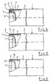
- FIG. 1 shows in the side partially sectioned illustration a container 1 intended to be pressurized To record medium.
- the container 1 itself consists of a Fiber-reinforced plastic material. Its shape becomes essentially formed from a tubular central part 2, at the ends of each arranged to close the tubular central part 2, a bottom 3 is.
- the bottom 3 is formed as a separate part, being himself also from the fiber-plastic composite material is made and the material of short, long or continuous fibers consists.
- the bottom 3 is in its use inwardly in the container space 4 arched, wherein on the curved bottom 3 a circumferential Collar 5 is arranged.
- This collar 5 in particular provides the connection area which is necessary to establish a solid bond between the inner wall 6 of the middle part 2 produce.
- the collar 5 lies directly on the inner wall 6 of the middle part 2 and is connected in this area with the inner wall 6 of the central part 2.
- FIG. 2 shows the possibility that the collar 5 with the wall 6 of the middle part 2 by means of a bolt, rivet or Screw connection 7 can be connected.
- FIG. 2 shows the possibility that the collar 5 with the wall 6 of the middle part 2 by means of a bolt, rivet or Screw connection 7 can be connected.
- Another way of making the connection of the collar 5 with the inner wall 6 of the middle part 2 through a fabric bond can also be used alternatively in Form of a bond or by welding done.
- connection options are after another Embodiment proposed, in particular shown in the Figure 5, that the collar 5 for producing connection an external thread 12, which with a on the inner wall 6 of the Wandungs Schemes arranged internal thread 13 corresponds.
- the bottom 3 can be easily and simply frontally in the Screw in middle part 2, whereby it must not be disregarded. that due to such a connection exists the possibility that Container easy to open, for example, for inspection purposes to inspect.
- Similar advantages are suggested by another proposal Connection, which consists in that the collar 5 by means of a Snap connection with the inner wall 6 of the middle part 2 connected is.
- a sealing ring 14 is arranged, which consists of the same thermoplastic the container 1 consists. This brings in particular the advantage that at a disposal of such containers 1 is not made a sorting must become. It can be used for sealing between the collar. 5 and the inner wall 6 during injection molding of the bottom 3 a flexurally soft Sealing lip 14.1, indicated in Figures 10 and 7, injected with become.
- the curved bottom 3 shows a ribbed structure 15, shown in FIG. 8 in a side view and in front view in the figure 9.
- these are by unidirectional Fiber composite strands 17 amplified, shown in Figure 11. It can - as in particular in the figure 10 in the side view too recognize - the ribbed structure 15 on both sides of the sealing surface be arranged of the bottom 3.
- line connections 20 and 21 are molded or molded.
- the curved bottom. 3 may also have a sandwich-like structure which is the corresponding one Quality and attitude characteristics for such Floor 3 has.
Landscapes
- Engineering & Computer Science (AREA)
- General Engineering & Computer Science (AREA)
- Mechanical Engineering (AREA)
- Pressure Vessels And Lids Thereof (AREA)
- Filling Or Discharging Of Gas Storage Vessels (AREA)
- Manipulator (AREA)
Description
- Figur 1:
- Eine teilweise geschnittene Seitenansicht des Behälters mit eingebundenem, nach innen gewölbten Boden:
- Figur 2:
- Eine weitere Ausführungsform gemäß der Figur 1 als Bolzenverbindung;
- Figur 3:
- Eine weitere Ausführungsform gemäß der Figur 1 als Stützringverbindung;
- Figur 4:
- Eine weitere Auführungsform gemäß der Figur 1 als Konusverbindung;
- Figur 5:
- Eine weitere Ausführungsform gemäß der Figur 1 als Gewinde- oder Schnappschlußverbindung;
- Figur 6:
- Eine weitere Ausführungsform gemäß der Figur 1 als Dichtringverbindung;
- Figur 7:
- Eine weitere Auführungsform gemäß der Figur 1 als Lippendichtverbindung;
- Figur 8:
- Eine weitere Auführungsform gemäß der Figur 1 in Seitenansicht mit verripptem Boden;
- Figur 9:
- Eine Stirnansicht des Bodens gemäß der Figur 8;
- Figur 10:
- Eine weitere Ausführungsform gemäß der Figur 8 als Doppelrippenboden;
- Figur 11:
- Eine weitere Ausführungsform gemäß der Figur 10 mit faserverstärkten Rippen.
Claims (16)
- Behälter (1) zur Aufnahme eines unter Druck stehenden Mediums, der im wesentlichen aus einem Faser-Kunststoff-Verbund-Material hergestellt ist, wobei dessen Form aus einem rohrförmigen Mittelteil (2) besteht, an dessen Enden zur Schließung des Behälters jeweils ein Boden (3) angeformt ist, wobei der als separates Teil ausgebildete Boden (3) ebenfalls aus einem Faser-Kunststoff-Verbund Material mit Kurz-, Lang- oder Endlosfasern besteht, wobei der Boden (3) gewölbt ausgebildet ist und an dem gewölbten Boden (3) ein umlaufender Kragen (5) angeordnet ist, der an der Innenwandung (6) des Mittelteils (2) anliegt und mit dieser verbunden ist, dadurch gekennzeichnet. daß der Boden (3) nach innen in den Behälterraum (4) gewölbt ausgebildet ist.
- Behälter nach Anspruch 1, dadurch gekennzeichnet, daß der Kragen mit der Wandung des Mittelteils mittels einer Bolzen-, Niet- oder Schraubverbindung (7) verbunden ist.
- Behälter nach Anspruch 1, dadurch gekennzeichnet, daß der Kragen (5) mit der Wandung (6) des Mittelteils (2) durch Stoffschluß, in Form einer Klebung oder auch mittels Schweißung verbunden wird.
- Behälter nach Anspruch 1, dadurch gekennzeichnet, daß die Verbindung des Kragens (5) mit der Wandung (6) des Mittelteils (2) durch Formschluß mit einem den Wandungsbereich des Mittelteils (2) einschnürenden Umfangringes (8) erfolgt.
- Behälter nach Anspruch 1, dadurch gekennzeichnet, daß zur Formschlußverbindung von Kragen (5) und Wandungsbereich (6), sowohl der Kragen (5) als auch der Wandungsbereich (6) zueinander korrespondierende Konusse (9 und 10) aufweisen, die mittels eines zusätzlichen an der Aussenwandung des Mittelteils (2) angeordneten Umfangringes (11) zusammenpreßbar sind.
- Behälter nach Anspruch 1, dadurch gekennzeichnet, daß zur Verbindung von Kragen (5) und Wandungsbereich (6) durch Reibschluß eine Schicht eingebracht ist, die derart beschaffen ist, daß der Reibungskoeffizient zwischen der Schicht und dem Kragen (5) einerseits und Schicht und dem Wandungsbereich (6) andererseits höher ist, als der Reibungskoeffizient zwischen Kragen (5) und Wandungsbereich (6) ohne Zusatzschicht.
- Behälter nach Anspruch 1, dadurch gekennzeichnet, daß der Kragen (5) zur herstellenden Verbindung ein Außengewinde (12) aufweist, welches mit einem an der Innenwandung (6) des Wandungsbereichs angeordneten Innengewinde (13) korrespondiert.
- Behälter nach Anspruch 1, dadurch gekennzeichnet, daß der Kragen (5) mittels einer Schnappverbindung mit der Innenwandung (6) des Mittelteils (2) verbunden ist.
- Behälter nach einem der Ansprüche 1 bis 8, dadurch gekennzeichnet, daß der Kragen (5) mit der Innenwandung (6) mittels einer Kombination aus Reib- und Stoffschluß oder einer Kombination aus Form- und Stoffschluß miteinander verbindbar ist.
- Behälter nach einem oder mehreren der vorhergehenden Ansprüche 1 bis 9, dadurch gekennzeichnet, daß zur Abdichtung zwischen dem Kragen (5) und der Innenwandung (6) ein Dichtungsring (14) angeordnet ist, der aus dem gleichen Thermoplast wie der Behälter (1) besteht.
- Behälter nach Anspruch 10, dadurch gekennzeichnet, daß zur Abdichtung zwischen dem Kragen (5) und der Innenwandung (6) beim Spritzgießen des Bodens (3) eine biegeweiche Dichtlippe (14.1) mit angeformt ist.
- Behälter nach Anspruch 1, dadurch gekennzeichnet, daß der gewölbte Boden (3) eine verrippte Struktur (15) aufweist.
- Behälter nach Anspruch 12, dadurch gekennzeichnet, daß zur Erzielung einer hohen Biege- und radialen Druckfestigkeit vorwiegend an den Zug- und Druckgurten der Rippen (16), diese durch unidirektionale Faserverbundstränge (17) verstärkt sind.
- Behälter nach Anspruch 13, dadurch gekennzeichnet, daß sich die Verrippung (15) auf beiden Seiten der Dichtfläche des Bodens (3) befindet.
- Behälter nach Anspruch 14, dadurch gekennzeichnet, daß in den Knotenpunkten (18 und 19) der Verrippungen (15) Leitungsanschlüsse (20 und 21) eingeformt bzw. mit angespritzt sind.
- Behälter nach Anspruch 1, dadurch gekennzeichnet, daß der gewölbte Boden (3) eine sandwichartige Struktur aufweist.
Priority Applications (5)
| Application Number | Priority Date | Filing Date | Title |
|---|---|---|---|
| DE1998132145 DE19832145B4 (de) | 1998-07-17 | 1998-07-17 | Behälter zur Aufnahme eines unter Druck stehenden Mediums |
| AT99118286T ATE270406T1 (de) | 1998-07-17 | 1999-09-15 | Behälter zur aufnahme eines unter druck stehenden mediums |
| EP99118286A EP1085243B1 (de) | 1998-07-17 | 1999-09-15 | Behälter zur Aufnahme eines unter Druck stehenden Mediums |
| ES99118286T ES2224516T3 (es) | 1998-07-17 | 1999-09-15 | Deposito para alojar un medio presurizado. |
| DE59909862T DE59909862D1 (de) | 1998-07-17 | 1999-09-15 | Behälter zur Aufnahme eines unter Druck stehenden Mediums |
Applications Claiming Priority (2)
| Application Number | Priority Date | Filing Date | Title |
|---|---|---|---|
| DE1998132145 DE19832145B4 (de) | 1998-07-17 | 1998-07-17 | Behälter zur Aufnahme eines unter Druck stehenden Mediums |
| EP99118286A EP1085243B1 (de) | 1998-07-17 | 1999-09-15 | Behälter zur Aufnahme eines unter Druck stehenden Mediums |
Publications (2)
| Publication Number | Publication Date |
|---|---|
| EP1085243A1 EP1085243A1 (de) | 2001-03-21 |
| EP1085243B1 true EP1085243B1 (de) | 2004-06-30 |
Family
ID=26047496
Family Applications (1)
| Application Number | Title | Priority Date | Filing Date |
|---|---|---|---|
| EP99118286A Expired - Lifetime EP1085243B1 (de) | 1998-07-17 | 1999-09-15 | Behälter zur Aufnahme eines unter Druck stehenden Mediums |
Country Status (4)
| Country | Link |
|---|---|
| EP (1) | EP1085243B1 (de) |
| AT (1) | ATE270406T1 (de) |
| DE (2) | DE19832145B4 (de) |
| ES (1) | ES2224516T3 (de) |
Cited By (1)
| Publication number | Priority date | Publication date | Assignee | Title |
|---|---|---|---|---|
| USD720836S1 (en) | 2013-06-07 | 2015-01-06 | Gary Morgan Moe | Fire department connection plug |
Families Citing this family (18)
| Publication number | Priority date | Publication date | Assignee | Title |
|---|---|---|---|---|
| DE19832145B4 (de) * | 1998-07-17 | 2004-11-18 | Linnemann-Schnetzer Gmbh | Behälter zur Aufnahme eines unter Druck stehenden Mediums |
| RU2213904C2 (ru) * | 2001-07-27 | 2003-10-10 | Акционерное общество закрытого типа фирма "ПРЭТТИ" | Баллон сварной высокого давления |
| EP1348910A1 (de) * | 2002-03-28 | 2003-10-01 | BS Manufacturing Limited | Kompakter Gaskocher |
| DE102006006902B4 (de) * | 2006-02-09 | 2008-02-21 | Gräfenthaler Kunststofftechnik GmbH | Druckbehälter aus Kunststoff und Verfahren zu seiner Herstellung |
| DE102006021020A1 (de) * | 2006-05-05 | 2007-11-08 | Man Nutzfahrzeuge Ag | Behälter in einem Kraftfahrzeug |
| DE102010008263B4 (de) * | 2010-02-17 | 2012-02-16 | Ute Abmayr | Druckbehälter und Verfahren zur Herstellung eines Druckbehälters |
| DE102010033623B4 (de) | 2010-08-06 | 2012-02-16 | Daimler Ag | Vorrichtung zum Speichern eines Mediums und Verfahren zum Herstellen einer solchen |
| BE1019903A5 (nl) * | 2011-04-08 | 2013-02-05 | Composite Tank Structures B V | Vat uit composietmateriaal, werkwijze voor het vervaardigen daarvan, en eindkap voor gebruik in een vat. |
| DE102013100591A1 (de) | 2013-01-21 | 2014-07-24 | Technische Universität Darmstadt | Druckbehälter sowie Verfahren zum Herstellen eines Druckbehälters |
| DE102013100594A1 (de) | 2013-01-21 | 2014-08-07 | Technische Universität Darmstadt | Druckbehälter sowie Verfahren zum Herstellen eines Druckbehälters |
| DE202015102088U1 (de) | 2015-04-27 | 2016-07-28 | Frauenthal Automotive Management Gmbh | Polkappe, insbesondere für einen Druckbehälter |
| DE202015102089U1 (de) | 2015-04-27 | 2016-08-01 | Frauenthal Automotive Management Gmbh | Druckbehälter zur Speicherung von unter Druck stehenden Fluiden |
| DE102015106461B4 (de) | 2015-04-27 | 2019-03-07 | Frauenthal Automotive Elterlein Gmbh | Polkappe, insbesondere für einen Druckbehälter sowie Verfahren zur Herstellung der Polkappe und Druckbehälter |
| DE102015106463B4 (de) | 2015-04-27 | 2022-11-03 | Frauenthal Automotive Elterlein Gmbh | Druckbehälter zur Speicherung von unter Druck stehenden Fluiden und Verfahren zur Herstellung des Druckbehälters |
| DE102015007047B4 (de) | 2015-05-29 | 2017-10-19 | Audi Ag | Verfahren und Vorrichtung zur Herstellung eines mit Druck beaufschlagbaren Behälters |
| DE102018222302B4 (de) * | 2018-12-19 | 2021-08-19 | Audi Ag | Verfahren zum Herstellen eines Drucktanks zur Speicherung von Brennstoff in einem Kraftfahrzeug und hiermit hergestellter Drucktank |
| DE102019203542B3 (de) * | 2019-03-15 | 2020-08-13 | Audi Ag | Drucktank zur Speicherung von Brennstoff in einem Kraftfahrzeug und Herstellverfahren (I) |
| FR3128950B1 (fr) * | 2021-11-05 | 2023-12-15 | Eifhytec | Contenant de fluide sous pression |
Citations (1)
| Publication number | Priority date | Publication date | Assignee | Title |
|---|---|---|---|---|
| DE1939919U (de) * | 1966-04-04 | 1966-06-02 | Rhodiaceta Ag | Kloepperboden mit verstaerkungsrippen. |
Family Cites Families (8)
| Publication number | Priority date | Publication date | Assignee | Title |
|---|---|---|---|---|
| US3095993A (en) * | 1958-11-05 | 1963-07-02 | White Sewing Machine Corp | Fiber glass tank |
| DE1185362B (de) * | 1963-09-19 | 1965-01-14 | Beteiligungs & Patentverw Gmbh | Behaelter fuer hohen Innendruck, insbesondere Druckbehaelter eines Kernreaktors |
| DE1894516U (de) * | 1964-01-31 | 1964-06-11 | Licentia Gmbh | Behaelterkoerper aus kunststoff, insbesondere feuerloeschgeraet. |
| US3366263A (en) * | 1964-07-15 | 1968-01-30 | Allegheny Ludlum Steel | Hot water tank |
| US3521604A (en) * | 1968-01-29 | 1970-07-28 | Smith Corp A O | Vessel having a foam polyurethane outer layer |
| DE3922577A1 (de) * | 1989-07-10 | 1991-01-24 | Asea Gmbh | Druckluftbehaelter aus faserverstaerktem kunststoff sowie verfahren und vorrichtung zu dessen herstellung |
| MY110038A (en) * | 1992-01-17 | 1997-11-29 | Morris White Pty Ltd | Fluid storage tank |
| DE19832145B4 (de) * | 1998-07-17 | 2004-11-18 | Linnemann-Schnetzer Gmbh | Behälter zur Aufnahme eines unter Druck stehenden Mediums |
-
1998
- 1998-07-17 DE DE1998132145 patent/DE19832145B4/de not_active Expired - Lifetime
-
1999
- 1999-09-15 DE DE59909862T patent/DE59909862D1/de not_active Expired - Lifetime
- 1999-09-15 EP EP99118286A patent/EP1085243B1/de not_active Expired - Lifetime
- 1999-09-15 AT AT99118286T patent/ATE270406T1/de active
- 1999-09-15 ES ES99118286T patent/ES2224516T3/es not_active Expired - Lifetime
Patent Citations (1)
| Publication number | Priority date | Publication date | Assignee | Title |
|---|---|---|---|---|
| DE1939919U (de) * | 1966-04-04 | 1966-06-02 | Rhodiaceta Ag | Kloepperboden mit verstaerkungsrippen. |
Cited By (1)
| Publication number | Priority date | Publication date | Assignee | Title |
|---|---|---|---|---|
| USD720836S1 (en) | 2013-06-07 | 2015-01-06 | Gary Morgan Moe | Fire department connection plug |
Also Published As
| Publication number | Publication date |
|---|---|
| DE19832145A1 (de) | 2000-02-03 |
| ATE270406T1 (de) | 2004-07-15 |
| DE19832145B4 (de) | 2004-11-18 |
| EP1085243A1 (de) | 2001-03-21 |
| DE59909862D1 (de) | 2004-08-05 |
| ES2224516T3 (es) | 2005-03-01 |
Similar Documents
| Publication | Publication Date | Title |
|---|---|---|
| DE19832145B4 (de) | Behälter zur Aufnahme eines unter Druck stehenden Mediums | |
| DE68921356T2 (de) | Druckgefäss. | |
| EP1859958B1 (de) | Flanschbauteil in Verbundbauweise sowie Verfahren zur Herstellung eines Flanschbauteils | |
| EP1200768B1 (de) | Druckbehälter und verfahren zu seiner herstellung | |
| EP3786511B1 (de) | Druckbehälter | |
| DE3103646C2 (de) | Druckbehälter zur Lagerung sowie zum Transport gasförmiger Strömungsmittel | |
| DE102014004157B4 (de) | Verfahren zur Herstellung von Lasteinleitungs-Flanschen an faserverstärkten Hohlprofilen mit thermoplastischer Matrix | |
| DE102016201477A1 (de) | Druckbehälter sowie Verfahren zur Herstellung eines Druckbehälters | |
| EP1989477A1 (de) | Druckbehälter zur speicherung von flüssigen oder gasförmigen medien | |
| EP0666450A1 (de) | Druckbehälter | |
| DE102006012699B4 (de) | Glasfaser verstärkte Struktur des Innenraums eines Kraftfahrzeuges | |
| DE102019001585A1 (de) | Faserverbundstrebe | |
| DE2613682A1 (de) | Vorrichtung fuer die elastische einspannung von glasfaserstaeben | |
| DE102020117307A1 (de) | Verfahren zur Herstellung eines Druckbehälters und Druckbehälter | |
| EP3445640A1 (de) | Strukturbauteil | |
| DE102017211625B4 (de) | Verfahren zur Herstellung einer Lagerbuchse, Lagerbuchse sowie Lenker für eine Radaufhängung eines Kraftfahrzeuges | |
| DE102017201420B4 (de) | Tank, insbesondere Drucktank, insbesondere Wasserstoff-Drucktank | |
| EP3898173B1 (de) | Kraftstoffbehälter für ein kraftfahrzeug und verfahren zur herstellung eines solchen kraftstoffbehälters und aussteifungselement für einen kraftstoffbehälter | |
| EP3947959A1 (de) | Anordnung, verfahren und werkzeug zum befestigen von bauteilen | |
| DE102021107165A1 (de) | Endboss-Abdichtung | |
| DE3420521A1 (de) | Fachwerk-knotenpunktverbindung | |
| DE102020134624A1 (de) | Boss für einen Drucktank und Drucktank für gasbetriebenes Fahrzeug | |
| DE102010030484A1 (de) | Modulares Leichtbau-Strebenelement | |
| DE3528133A1 (de) | Verfahren und vorrichtung zum armieren eines rohrstueckfoermigen teils eines koerpers, insbesondere eines rohres | |
| EP3557117A2 (de) | Druckbehälter sowie verfahren zur anbindung eines druckbehälters in eine karosseriestruktur |
Legal Events
| Date | Code | Title | Description |
|---|---|---|---|
| PUAI | Public reference made under article 153(3) epc to a published international application that has entered the european phase |
Free format text: ORIGINAL CODE: 0009012 |
|
| AK | Designated contracting states |
Kind code of ref document: A1 Designated state(s): AT BE CH CY DE DK ES FI FR GB GR IE IT LI LU MC NL PT SE |
|
| AX | Request for extension of the european patent |
Free format text: AL;LT;LV;MK;RO;SI |
|
| 17P | Request for examination filed |
Effective date: 20010911 |
|
| AKX | Designation fees paid |
Free format text: AT BE CH CY DE DK ES FI FR GB GR IE IT LI LU MC NL PT SE |
|
| 17Q | First examination report despatched |
Effective date: 20030514 |
|
| GRAP | Despatch of communication of intention to grant a patent |
Free format text: ORIGINAL CODE: EPIDOSNIGR1 |
|
| GRAS | Grant fee paid |
Free format text: ORIGINAL CODE: EPIDOSNIGR3 |
|
| GRAA | (expected) grant |
Free format text: ORIGINAL CODE: 0009210 |
|
| AK | Designated contracting states |
Kind code of ref document: B1 Designated state(s): AT BE CH CY DE DK ES FI FR GB GR IE IT LI LU MC NL PT SE |
|
| PG25 | Lapsed in a contracting state [announced via postgrant information from national office to epo] |
Ref country code: NL Free format text: LAPSE BECAUSE OF FAILURE TO SUBMIT A TRANSLATION OF THE DESCRIPTION OR TO PAY THE FEE WITHIN THE PRESCRIBED TIME-LIMIT Effective date: 20040630 Ref country code: IT Free format text: LAPSE BECAUSE OF FAILURE TO SUBMIT A TRANSLATION OF THE DESCRIPTION OR TO PAY THE FEE WITHIN THE PRE;WARNING: LAPSES OF ITALIAN PATENTS WITH EFFECTIVE DATE BEFORE 2007 MAY HAVE OCCURRED AT ANY TIME BEFORE 2007. THE CORRECT EFFECTIVE DATE MAY BE DIFFERENT FROM THE ONE RECORDED.SCRIBED TIME-LIMIT Effective date: 20040630 Ref country code: FI Free format text: LAPSE BECAUSE OF FAILURE TO SUBMIT A TRANSLATION OF THE DESCRIPTION OR TO PAY THE FEE WITHIN THE PRESCRIBED TIME-LIMIT Effective date: 20040630 Ref country code: CY Free format text: LAPSE BECAUSE OF FAILURE TO SUBMIT A TRANSLATION OF THE DESCRIPTION OR TO PAY THE FEE WITHIN THE PRESCRIBED TIME-LIMIT Effective date: 20040630 |
|
| REG | Reference to a national code |
Ref country code: GB Ref legal event code: FG4D Free format text: NOT ENGLISH Ref country code: CH Ref legal event code: EP |
|
| REG | Reference to a national code |
Ref country code: IE Ref legal event code: FG4D Free format text: GERMAN |
|
| REF | Corresponds to: |
Ref document number: 59909862 Country of ref document: DE Date of ref document: 20040805 Kind code of ref document: P |
|
| PG25 | Lapsed in a contracting state [announced via postgrant information from national office to epo] |
Ref country code: LU Free format text: LAPSE BECAUSE OF NON-PAYMENT OF DUE FEES Effective date: 20040915 |
|
| PG25 | Lapsed in a contracting state [announced via postgrant information from national office to epo] |
Ref country code: MC Free format text: LAPSE BECAUSE OF NON-PAYMENT OF DUE FEES Effective date: 20040930 Ref country code: LI Free format text: LAPSE BECAUSE OF NON-PAYMENT OF DUE FEES Effective date: 20040930 Ref country code: GR Free format text: LAPSE BECAUSE OF FAILURE TO SUBMIT A TRANSLATION OF THE DESCRIPTION OR TO PAY THE FEE WITHIN THE PRESCRIBED TIME-LIMIT Effective date: 20040930 Ref country code: DK Free format text: LAPSE BECAUSE OF FAILURE TO SUBMIT A TRANSLATION OF THE DESCRIPTION OR TO PAY THE FEE WITHIN THE PRESCRIBED TIME-LIMIT Effective date: 20040930 Ref country code: CH Free format text: LAPSE BECAUSE OF NON-PAYMENT OF DUE FEES Effective date: 20040930 Ref country code: BE Free format text: LAPSE BECAUSE OF NON-PAYMENT OF DUE FEES Effective date: 20040930 |
|
| REG | Reference to a national code |
Ref country code: SE Ref legal event code: TRGR |
|
| GBT | Gb: translation of ep patent filed (gb section 77(6)(a)/1977) |
Effective date: 20040922 |
|
| NLV1 | Nl: lapsed or annulled due to failure to fulfill the requirements of art. 29p and 29m of the patents act | ||
| REG | Reference to a national code |
Ref country code: ES Ref legal event code: FG2A Ref document number: 2224516 Country of ref document: ES Kind code of ref document: T3 |
|
| ET | Fr: translation filed | ||
| BERE | Be: lapsed |
Owner name: LINNEMANN-SCHNETZER G.M.B.H. Effective date: 20040930 |
|
| PLBE | No opposition filed within time limit |
Free format text: ORIGINAL CODE: 0009261 |
|
| STAA | Information on the status of an ep patent application or granted ep patent |
Free format text: STATUS: NO OPPOSITION FILED WITHIN TIME LIMIT |
|
| REG | Reference to a national code |
Ref country code: CH Ref legal event code: PL |
|
| 26N | No opposition filed |
Effective date: 20050331 |
|
| BERE | Be: lapsed |
Owner name: *LINNEMANN-SCHNETZER G.M.B.H. Effective date: 20040930 |
|
| PG25 | Lapsed in a contracting state [announced via postgrant information from national office to epo] |
Ref country code: PT Free format text: LAPSE BECAUSE OF NON-PAYMENT OF DUE FEES Effective date: 20041130 |
|
| REG | Reference to a national code |
Ref country code: ES Ref legal event code: PC2A |
|
| REG | Reference to a national code |
Ref country code: GB Ref legal event code: S117 Free format text: REQUEST FILED; REQUEST FOR CORRECTION UNDER SECTION 117 FILED ON 30 MARCH 2010 |
|
| REG | Reference to a national code |
Ref country code: FR Ref legal event code: TP Ref country code: FR Ref legal event code: RM |
|
| REG | Reference to a national code |
Ref country code: GB Ref legal event code: 732E Free format text: REGISTERED BETWEEN 20101014 AND 20101020 |
|
| REG | Reference to a national code |
Ref country code: GB Ref legal event code: S117 Free format text: CORRECTIONS ALLOWED; REQUEST FOR CORRECTION UNDER SECTION 117 FILED ON 30 MARCH 2010 ALLOWED ON 24 AUGUST 2010 |
|
| REG | Reference to a national code |
Ref country code: DE Ref legal event code: R082 Ref document number: 59909862 Country of ref document: DE Representative=s name: PATENTANWAELTE MELDAU - STRAUSS - FLOETOTTO, DE |
|
| REG | Reference to a national code |
Ref country code: DE Ref legal event code: R082 Ref document number: 59909862 Country of ref document: DE Representative=s name: PATENTANWAELTE MELDAU - STRAUSS - FLOETOTTO, DE Effective date: 20120921 Ref country code: DE Ref legal event code: R081 Ref document number: 59909862 Country of ref document: DE Owner name: FRAUENTHAL AUTOMOTIVE MANAGEMENT GMBH, DE Free format text: FORMER OWNER: FRAUENTHAL DEUTSCHLAND GMBH, 59229 AHLEN, DE Effective date: 20120921 |
|
| REG | Reference to a national code |
Ref country code: FR Ref legal event code: CD Owner name: FRAUENTHAL AUTOMOTIVE MANAGEMENT GMBH, DE Effective date: 20121107 |
|
| REG | Reference to a national code |
Ref country code: AT Ref legal event code: HC Ref document number: 270406 Country of ref document: AT Kind code of ref document: T Owner name: FRAUENTHAL AUTOMOTIVE MANAGEMENT GMBH, DE Effective date: 20130307 |
|
| REG | Reference to a national code |
Ref country code: ES Ref legal event code: PC2A Owner name: FRAUENTHAL AUTOMOTIVE MANAGEMENT GMBH Effective date: 20130418 |
|
| REG | Reference to a national code |
Ref country code: FR Ref legal event code: PLFP Year of fee payment: 18 |
|
| REG | Reference to a national code |
Ref country code: FR Ref legal event code: PLFP Year of fee payment: 19 |
|
| PGFP | Annual fee paid to national office [announced via postgrant information from national office to epo] |
Ref country code: DE Payment date: 20170811 Year of fee payment: 19 Ref country code: FR Payment date: 20170818 Year of fee payment: 19 Ref country code: GB Payment date: 20170925 Year of fee payment: 19 |
|
| PGFP | Annual fee paid to national office [announced via postgrant information from national office to epo] |
Ref country code: SE Payment date: 20170920 Year of fee payment: 19 Ref country code: IE Payment date: 20170901 Year of fee payment: 19 Ref country code: AT Payment date: 20170928 Year of fee payment: 19 |
|
| PGFP | Annual fee paid to national office [announced via postgrant information from national office to epo] |
Ref country code: ES Payment date: 20171009 Year of fee payment: 19 |
|
| REG | Reference to a national code |
Ref country code: DE Ref legal event code: R082 Ref document number: 59909862 Country of ref document: DE Representative=s name: BAUER WAGNER PRIESMEYER PATENT- UND RECHTSANWA, DE |
|
| REG | Reference to a national code |
Ref country code: DE Ref legal event code: R119 Ref document number: 59909862 Country of ref document: DE |
|
| REG | Reference to a national code |
Ref country code: SE Ref legal event code: EUG |
|
| REG | Reference to a national code |
Ref country code: AT Ref legal event code: MM01 Ref document number: 270406 Country of ref document: AT Kind code of ref document: T Effective date: 20180915 |
|
| GBPC | Gb: european patent ceased through non-payment of renewal fee |
Effective date: 20180915 |
|
| PG25 | Lapsed in a contracting state [announced via postgrant information from national office to epo] |
Ref country code: SE Free format text: LAPSE BECAUSE OF NON-PAYMENT OF DUE FEES Effective date: 20180916 |
|
| REG | Reference to a national code |
Ref country code: IE Ref legal event code: MM4A |
|
| PG25 | Lapsed in a contracting state [announced via postgrant information from national office to epo] |
Ref country code: IE Free format text: LAPSE BECAUSE OF NON-PAYMENT OF DUE FEES Effective date: 20180915 Ref country code: DE Free format text: LAPSE BECAUSE OF NON-PAYMENT OF DUE FEES Effective date: 20190402 |
|
| PG25 | Lapsed in a contracting state [announced via postgrant information from national office to epo] |
Ref country code: FR Free format text: LAPSE BECAUSE OF NON-PAYMENT OF DUE FEES Effective date: 20180930 |
|
| REG | Reference to a national code |
Ref country code: ES Ref legal event code: FD2A Effective date: 20191030 |
|
| PG25 | Lapsed in a contracting state [announced via postgrant information from national office to epo] |
Ref country code: GB Free format text: LAPSE BECAUSE OF NON-PAYMENT OF DUE FEES Effective date: 20180915 Ref country code: AT Free format text: LAPSE BECAUSE OF NON-PAYMENT OF DUE FEES Effective date: 20180915 |
|
| PG25 | Lapsed in a contracting state [announced via postgrant information from national office to epo] |
Ref country code: ES Free format text: LAPSE BECAUSE OF NON-PAYMENT OF DUE FEES Effective date: 20180916 |