EP1084986A1 - Material-handling vehicle - Google Patents
Material-handling vehicle Download PDFInfo
- Publication number
- EP1084986A1 EP1084986A1 EP00119916A EP00119916A EP1084986A1 EP 1084986 A1 EP1084986 A1 EP 1084986A1 EP 00119916 A EP00119916 A EP 00119916A EP 00119916 A EP00119916 A EP 00119916A EP 1084986 A1 EP1084986 A1 EP 1084986A1
- Authority
- EP
- European Patent Office
- Prior art keywords
- output
- vehicle
- engine
- vehicle according
- disposed
- Prior art date
- Legal status (The legal status is an assumption and is not a legal conclusion. Google has not performed a legal analysis and makes no representation as to the accuracy of the status listed.)
- Granted
Links
- 230000008859 change Effects 0.000 claims abstract description 39
- 230000005540 biological transmission Effects 0.000 claims description 44
- 239000000463 material Substances 0.000 claims description 6
- 238000001816 cooling Methods 0.000 claims description 4
- 239000012530 fluid Substances 0.000 claims description 4
- 230000001419 dependent effect Effects 0.000 claims 6
- 230000008878 coupling Effects 0.000 description 3
- 238000010168 coupling process Methods 0.000 description 3
- 238000005859 coupling reaction Methods 0.000 description 3
- 230000007246 mechanism Effects 0.000 description 2
- 238000000034 method Methods 0.000 description 2
- 238000002485 combustion reaction Methods 0.000 description 1
- 238000013016 damping Methods 0.000 description 1
- 239000011521 glass Substances 0.000 description 1
- 230000001970 hydrokinetic effect Effects 0.000 description 1
- 230000002706 hydrostatic effect Effects 0.000 description 1
- 230000009347 mechanical transmission Effects 0.000 description 1
- 230000010355 oscillation Effects 0.000 description 1
- 230000008569 process Effects 0.000 description 1
- 230000001681 protective effect Effects 0.000 description 1
- 238000009423 ventilation Methods 0.000 description 1
Images



Classifications
-
- B—PERFORMING OPERATIONS; TRANSPORTING
- B66—HOISTING; LIFTING; HAULING
- B66F—HOISTING, LIFTING, HAULING OR PUSHING, NOT OTHERWISE PROVIDED FOR, e.g. DEVICES WHICH APPLY A LIFTING OR PUSHING FORCE DIRECTLY TO THE SURFACE OF A LOAD
- B66F9/00—Devices for lifting or lowering bulky or heavy goods for loading or unloading purposes
- B66F9/06—Devices for lifting or lowering bulky or heavy goods for loading or unloading purposes movable, with their loads, on wheels or the like, e.g. fork-lift trucks
- B66F9/065—Devices for lifting or lowering bulky or heavy goods for loading or unloading purposes movable, with their loads, on wheels or the like, e.g. fork-lift trucks non-masted
- B66F9/0655—Devices for lifting or lowering bulky or heavy goods for loading or unloading purposes movable, with their loads, on wheels or the like, e.g. fork-lift trucks non-masted with a telescopic boom
-
- B—PERFORMING OPERATIONS; TRANSPORTING
- B60—VEHICLES IN GENERAL
- B60K—ARRANGEMENT OR MOUNTING OF PROPULSION UNITS OR OF TRANSMISSIONS IN VEHICLES; ARRANGEMENT OR MOUNTING OF PLURAL DIVERSE PRIME-MOVERS IN VEHICLES; AUXILIARY DRIVES FOR VEHICLES; INSTRUMENTATION OR DASHBOARDS FOR VEHICLES; ARRANGEMENTS IN CONNECTION WITH COOLING, AIR INTAKE, GAS EXHAUST OR FUEL SUPPLY OF PROPULSION UNITS IN VEHICLES
- B60K17/00—Arrangement or mounting of transmissions in vehicles
-
- B—PERFORMING OPERATIONS; TRANSPORTING
- B60—VEHICLES IN GENERAL
- B60K—ARRANGEMENT OR MOUNTING OF PROPULSION UNITS OR OF TRANSMISSIONS IN VEHICLES; ARRANGEMENT OR MOUNTING OF PLURAL DIVERSE PRIME-MOVERS IN VEHICLES; AUXILIARY DRIVES FOR VEHICLES; INSTRUMENTATION OR DASHBOARDS FOR VEHICLES; ARRANGEMENTS IN CONNECTION WITH COOLING, AIR INTAKE, GAS EXHAUST OR FUEL SUPPLY OF PROPULSION UNITS IN VEHICLES
- B60K17/00—Arrangement or mounting of transmissions in vehicles
- B60K17/34—Arrangement or mounting of transmissions in vehicles for driving both front and rear wheels, e.g. four wheel drive vehicles
-
- B—PERFORMING OPERATIONS; TRANSPORTING
- B60—VEHICLES IN GENERAL
- B60K—ARRANGEMENT OR MOUNTING OF PROPULSION UNITS OR OF TRANSMISSIONS IN VEHICLES; ARRANGEMENT OR MOUNTING OF PLURAL DIVERSE PRIME-MOVERS IN VEHICLES; AUXILIARY DRIVES FOR VEHICLES; INSTRUMENTATION OR DASHBOARDS FOR VEHICLES; ARRANGEMENTS IN CONNECTION WITH COOLING, AIR INTAKE, GAS EXHAUST OR FUEL SUPPLY OF PROPULSION UNITS IN VEHICLES
- B60K5/00—Arrangement or mounting of internal-combustion or jet-propulsion units
- B60K5/02—Arrangement or mounting of internal-combustion or jet-propulsion units with the engine main axis, e.g. crankshaft axis, substantially in or parallel to the longitudinal centre line of the vehicle
-
- B—PERFORMING OPERATIONS; TRANSPORTING
- B60—VEHICLES IN GENERAL
- B60K—ARRANGEMENT OR MOUNTING OF PROPULSION UNITS OR OF TRANSMISSIONS IN VEHICLES; ARRANGEMENT OR MOUNTING OF PLURAL DIVERSE PRIME-MOVERS IN VEHICLES; AUXILIARY DRIVES FOR VEHICLES; INSTRUMENTATION OR DASHBOARDS FOR VEHICLES; ARRANGEMENTS IN CONNECTION WITH COOLING, AIR INTAKE, GAS EXHAUST OR FUEL SUPPLY OF PROPULSION UNITS IN VEHICLES
- B60K5/00—Arrangement or mounting of internal-combustion or jet-propulsion units
- B60K5/12—Arrangement of engine supports
Definitions
- This invention relates to a material-handling vehicle of the kind, hereinafter referred to as the "kind specified", including a structure having ground engageable propulsion means, a loader arm mounted on the structure for up and down swinging movement and, on opposite sides of the loader arm, an operator's cab and an engine having an output to provide power for said movement of the loader arm and for propulsion of the vehicle and a drive to connect the output of the engine to the ground engageable propulsion means to propel the vehicle.
- WO-A-89/00972 CA-A-2,009,968, EP-A-0,656,315, US 5836733 disclose vehicles of the kind specified in which a loader arm, in a fully lowered position, is substantially horizontal, and is at least partly accommodated in a well disposed between the operator's cab and a housing in which the engine is disposed.
- the loader arm is disposed so it does not, at least substantially, interfere with the view of the operator in a direction over the top of the engine housing.
- a side mounted longitudinally orientated engine connected by a hydrostatic drive is known from the vehicle produced commercially and the general layout of which is disclosed in WO-A-89/00972.
- CA-A-2,009,968 and GB-A-2268155 disclose a side mounted longitudinally orientated engine having a drive in which the gearbox is mounted directly to the engine or, in one embodiment of CA-A-2,009,968, the gearbox is mounted substantially on the longitudinal axis of the machine.
- the former arrangement leads a relatively long wheel base machine, whilst the latter requires a large and often complex transfer drive between the gearbox and the engine.
- EP-A-0,656,316 and DD-A-240869 and US 5,836,733 the engine is disposed with its output transversely of the vehicle and an angle gear drive is provided to transfer drive through 90° from the engine to a gearbox from which drive is transmitted to the ground engageable means.
- the input of the change speed gear train may be disposed transversely of the vehicle.
- An object of the present invention is to provide a material-handling vehicle of the kind specified whereby the above mentioned problems are overcome or are reduced.
- the drive includes an angle drive and a change speed gear train
- the output of the engine is kinematically connected to an input of the angle drive and an output of the angle drive is kinematically connected to an input of the change speed gear train
- an output of the change speed gear train is kinematically connected to the ground engageable propulsion means wherein the output of the engine and the input of the angle drive are disposed longitudinally of the vehicle whilst the output of the angle drive is disposed transversely of the vehicle.
- the input of the change speed gear may be disposed transversely of the vehicle.
- the output of the change speed gear train may be disposed transversely of the vehicle.
- the drive means may include means for disconnecting the drive between the engine and the ground engageable propulsion means.
- Said disconnecting means may be disposed between the engine and the angle drive or between the change speed gear train and the ground engageable propulsion means but is preferably between the angle drive and the change speed gear train.
- the disconnecting means may comprise a mechanical clutch, such as a friction clutch, a fluid coupling or a torque converter or the like.
- the engine may have a drive shaft which is disposed longitudinally of the vehicle.
- the engine may be a reciprocatory engine and have a crankshaft which provides said drive shaft.
- the change speed gear train may be disposed in a housing comprising a gearbox.
- the angle drive and the change speed gear train may be disposed in at least one housing, the housing or housings comprising a transmission unit.
- the vehicle may comprise a chassis having a pair of spaced longitudinally extending frame members.
- the frame members may be parallel to each other.
- At least one of the chassis frame members may be apertured or relieved locally to clear at least one of the engine, gearbox, transmission unit or associated component.
- the transmission unit may be provided with at least one output which is kinematically connected to said ground engageable propulsion means.
- the at least one output may be disposed on or parallel to a longitudinal axis of the vehicle.
- the transmission unit may have a front output and a rear output.
- Said outputs of the transmission unit may be provided at opposite ends of a shaft, which is driven by the output of the change speed gear train, and which is disposed longitudinally of the vehicle.
- the output of the change speed gear train may be connected to an input of a further angle drive having an output which extends longitudinally of the vehicle
- the output of the change speed gear train may be connected to an input of a further angle drive having an output which is kinematically connected to said outputs of the transmission unit.
- the output of the further angle drive may be disposed adjacent the engine.
- the further angle drive may be disposed adjacent to the engine.
- the vehicle may comprise a front axle and a rear axle each having a ground engageable propulsion means and the propulsion means of at least one of said axles being connected to said at least one output of the transmission unit.
- At least one of said axles may have a differential which is connected to said at least one output of the transmission unit.
- connection of the or each output of the transmission unit to at least one of said axles may comprise a shaft which may have a universal joint at least at one end.
- the change speed gear train may be disposed substantially within the chassis frame members and between the axes of rotation of the front and rear wheels of the vehicle.
- the engine may be spaced from the cab to define a well between the cab and the engine in which the arm, in a lowered position, can be at least partly accommodated.
- the well may be disposed between the chassis frame members.
- the engine may be disposed in a housing.
- the engine may be disposed substantially on the opposite side of the chassis to the cab.
- Mounting means may be provided between the structure and at least one of the engine and transmission unit.
- Mounting means may be provided between the structure and the transmission unit and the engine may be carried by the transmission unit.
- a first mounting means may be provided between a first chassis frame member, which is adjacent the operator's cab and the transmission unit, a second mounting means may be provided between the other frame chassis member and the transmission unit and a third mounting means may be provided between a part of the structure and the transmission unit.
- the mounting means may comprise compliant mounts.
- the transmission unit may comprise an angle drive housing for said angle drive and a gearbox for said change speed gear train.
- the gearbox may be disposed underneath the well.
- the engine, angle drive housing and change speed gearbox may be rigidly connected together.
- the angle drive housing may have a first mounting face, which faces longitudinally of the vehicle, to which a mounting face of the engine is connected, and a second mounting face, which faces transversely of the vehicle, to which a mounting face of the gearbox is connected.
- the gearbox may have said first mounting means which may be disposed on the opposite side of the longitudinal axis of the vehicle to the engine.
- the angle drive housing may have said second and third mounting means which may be disposed on transversely opposite sides of the axis of rotation of the output of the engine.
- the longitudinal axis of the loader arm may extend forwardly in, or parallel to, a vertical plane containing a longitudinal axis of the vehicle.
- the structure may have a front end and a rear end with said longitudinal axis of the vehicle extending therebetween and the ground engageable propulsion means being disposed equi-distant from, and on opposite sides of, said longitudinal axis.
- the loader arm may be pivotally mounted on the structure about a horizontal axis adjacent the rear of the vehicle.
- the loader arm may carry a material handling implement at its front end so that the material handling implement is disposed in front of the front of the structure when the arm is in its lowermost position.
- the cab may have a side window which faces transversely across the vehicle, preferably at right angles to the longitudinal axis of the loader arm.
- the top of the loader arm in a fully lowered position and at a position alongside the top of a steering wheel in the operator's cab may be disposed wholly or substantially wholly below a horizontal plane which is not more than 1 metre, or preferably not more than 0.5. metre, above the top of the steering wheel so that the driver's vision is substantially unobstructed by the loader arm.
- the top of the boom at said position may be wholly or substantially wholly below a horizontal plane containing the top of the steering wheel.
- the loader arm may be telescopic in the direction of the longitudinal axis of the loader arm.
- the longitudinal axis of the loader arm may be in a substantially horizontal plane when the loader arm is in a position in which the implement engages a horizontal plane on which the ground engageable propulsion means are supported and, if the loader arm is telescopic, the loader arm is fully retracted.
- the engine may be disposed so that a major portion of the engine is situated below a plane tangent to the top of the ground engaging propulsion means so as not to interfere with the view of an operator working in the operator's cab.
- the ground engageable propulsion means may comprise a pair of ground engageable wheels disposed adjacent the front of the structure and a pair of rear ground engageable wheels adjacent the rear of the structure.
- the wheels of the front pair may be driven from the front output of the transmission whilst the wheels of the rear pair may be driven from the rear output of the transmission.
- the ground engageable propulsion means may be driven from the engine wholly by a mechanical transmission or a hydrokinetic transmission.
- the angle drive and/or the further angle drive may comprise first and second shafts disposed at an angle to each other, the first shaft being connected to or comprising the input shaft of the angle drive and the second shaft being connected to or comprising the output of the angle drive and the first and second shafts being connectable in torque transmitting relationship.
- Said first and second shafts may connectable in said torque transmitting relationship by a bevel gear set.
- the first and second shafts may be mutually inclined at 90°.
- the angle drive and/or the front axle drive may comprise a first bevel gear mounted for rotation about an axis which extends longitudinally of the vehicle and which is in mesh with a second bevel gear which is mounted for rotation about an axis which extends transversely of the vehicle.
- Damping means may be provided between the engine output and the drive to reduce engine induced vibrational resonance.
- the present invention gives at least one of the following advantages.
- Such pump or pumps may be either transversely and/or longitudinally disposed so as to be driven by transversely and/or longitudinally disposed shafts of the angle drive.
- more than one pump may be provided and in this case one pump may be driven from the transversely orientated shaft of the angle drive, whilst a second pump may be driven by a longitudinally orientated shaft of the angle drive.
- a compact drive train is achieved which can have a three point mounting providing a transmission unit which is rigidly connected to the engine which is carried in cantilever from the transmission unit.
- a cooling radiator for the engine may be disposed above the angle drive.
- a material-handling vehicle is indicated generally at 10 and comprises a main structure 11 having a front end 12 and a rear end 13 with a longitudinal axis X-X extending between the front and rear ends.
- the structure 11 comprises a pair of spaced parallel frame members 14, 15 held in spaced parallel relationship by cross members.
- Each frame member 14, 15 has a upper surface 21, 22 respectively. At the front and rear, the frame members 14, 15 have generally upright parts 24, 25 respectively whilst on their undersides they have a lower surface one of which is shown at 27.
- the right-hand frame member 15 has an upwardly relieved part 28 to provide clearance for an engine and a transmission unit as hereinafter to be described.
- a front axle 30 is mounted on the frame members 14, 15 at the front end thereof whilst a rear axle 31 is mounted on the frame members 14, 15 towards the rear thereof.
- the axles 30, 31 are of conventional type carrying at their opposite ends front wheels 33 and rear wheels 34 respectively. Both the front wheels 33 and both rear wheels 34 are pivotable relative to their associated axis about a steering axis V for steering movement of the vehicle, If desired at least one of the axles may be mounted relative to the frame members 14, 15 for oscillation about a longitudinally extending axis.
- Each axle 30, 31 is provided with a differential 35, 36 respectively of conventional form, the differentials being driven by propeller shafts 37, 38 respectively from front and rear output couplings 39, 40 respectively of a transmission unit 41.
- the transmission unit 41 incorporates a change speed gear train, shown in block diagrammatic form at 42, disposed in a gear box 43, a torque converter 44 and an angle drive in an angle drive housing 45. If desired the torque converter 44 may be omitted or other means for disconnecting drive when the vehicle is stationary may be provided, such as a mechanical clutch, for example, a friction clutch, or a fluid coupling.
- a mechanical clutch for example, a friction clutch, or a fluid coupling.
- the gearbox 43 is, in the present example, a power shift gearbox where the gears and direction of rotation of the change speed gear train are selected by solenoid controlled hydraulically actuated clutch packs. If desired, the gearbox may be of a type where the gear or direction of rotation of the change speed gear train is mechanically selected or a combination of mechanical and clutch pack selection may be used.
- the change speed gear train 42 has an output shaft 61 a at the end thereof adjacent the angle drive housing 45, which has affixed, thereto to rotate therewith, a pinion 64 a which meshes with a pinion 64 b splined to an intermediate shaft 65 which has a first bevel gear 66 formed integrally therewith.
- the bevel gear 66 meshes with a second bevel gear 67 splined to a shaft 68 which is provided with the forward and rearward outputs 39, 40 respectively.
- the outputs 39, 40 are beneath the torque converter 44 and so are disposed at the end of the transmission to be adjacent to the engine.
- the shafts 65 and 68 are carried in the gearbox 43 by bearings 69 a , 69 b respectively.
- the shaft 65, first bevel gear 66, second bevel gear 67 and shaft 68 provide an input shaft, meshed gears and an output shaft, respectively of a further angle drive which in the present example is disposed in the housing 45 which is part of the transmission unit.
- the gearbox 43 is disposed essentially between the frame members 14, 15.
- a first mounting face 47 of the angle drive housing 45 is bolted to an opposed face 48 of an engine 49.
- a second mounting face 50 of the angle drive housing, disposed at right angles to the face 47, is bolted to an opposed mounting face 51 of the gearbox 43.
- the transmission unit 41 is mounted on the frame members 14, 15 by three compliant mounts 46 a - c .
- a first mount 46 a is provided between the first frame member 14, which is adjacent the operator's cab, and the gearbox 43.
- a second mount 46 b is provided between the second frame member 15 and the angle drive housing 45.
- a third mounting 46 c is provided between a part projecting transversely from the frame member 15 and the angle drive housing 45 on the opposite of the longitudinal axis of the engine to the frame member 15.
- the engine 49 is supported in cantilever by virtue of the mounting face 48 of the engine being connected to the mounting face 47 of the angle drive housing 45.
- the torque converter 44 may be disposed wholly or partly in the gearbox 43 or in the angle drive housing 45 or may be provided partially in each thereof. Alternatively a separate housing may be provided for all or part of the torque converter 44 appropriately disposed between the gearbox 43 and the angle drive housing 45.
- the engine 49 is, in the present example, a four cylinder engine having a crankshaft indicated diagrammatically at 52 which is rotatable about an axis which is parallel to the longitudinal axis X-X of the vehicle i.e. an axis which is midway between the ground engageable propulsion means on either side of the vehicle and which intersects the axis of rotation of the front and rear ground engageable propulsion means.
- the crankshaft 52 provides a drive shaft of the engine.
- the engine may be of other type such as a rotary engine such as a Wankel engine or a turbine.
- a rotary engine such as a Wankel engine or a turbine.
- the rotor shaft or the turbine shaft respectively provides the drive shaft.
- an angle drive which, as best shown in Figure 4, carries in suitable bearing means an input shaft 53 which is connected via a vibration damper 54 to the engine output, provided in this example by a flywheel 55 on the drive shaft 52.
- the angle drive also carries in suitable bearing means an output shaft 56 which is connected via the torque converter 44 to an input shaft 57 of the change speed gear train incorporated in the gearbox 43.
- the input and output shafts 53, 56 provide first and second shafts which have a bevel gear 53 a , 56 a respectively fixed relative thereto, in the present example by being formed integrally therewith, and which are interengaged to transmit torque between the engine and the gearbox and to turn the direction of drive through 90° from a longitudinal direction to a transverse direction.
- first and second shafts may be formed separately from the input and output shafts and may be connected to them in any suitable manner. If desired, the input and output shafts may rotate about different axes to the first and second shafts and may be connected thereto by suitable gear means.
- the output shaft 56 is connected by a quill shaft 58 to a hydraulic pump 59 bolted to the housing 45.
- the hydraulic pump 59 may be orientated in the dotted line position shown in Figure 1 in which case the pump may be driven by the input bevel gear shaft.
- the torque converter 44 is housed by virtue of the transfer box 45 having an extension part 45 a which provides a first torque converter housing part which cooperates with a second torque converter housing part 43 a of the gearbox 43 to provide a housing for the torque converter 44
- the torque converter housing part may be separate from and bolted to the transfer box 45.
- the torque converter may be housed in any other desired manner so as to be operatively disposed between the change speed gear train and the angle drive or in another suitable disposition of the drive path such as between the engine and the angle drive or between the change speed gear train and the ground engaging propulsion means.
- the engine is provided with a suitable cooling radiator but not shown. If desired this may be provided in the space to the rear of the engine above the angle drive housing 45.
- the engine 49 is disposed substantially wholly to the front of a longitudinal midpoint between the axis R F and R R and the gearbox and transfer box substantially wholly to the rear of such midpoint
- the engine may be disposed at any desired longitudinal position between the wheels and the gearbox may be positioned at a desired longitudinal position of the machine with a suitable spacing mechanism or connecting mechanism being provided between the engine and the angle drive housing where the angle drive is connected to the gearbox as described hereinbefore.
- suitable means may be provided to connect the output of the transfer box to the input of the gearbox where these components are longitudinally offset.
- the distance between the outside of the frame members 14, 15 may be not more than 30% of the overall width of the machine excluding the wheels and may be, for example, in the range 27%-30%.
- An operator's cab 70 is mounted on the frame member 14 by vibration isolating mounts so that the cab 70 is supported on one side of the longitudinal axis X-X of the vehicle.
- the cab 70 has a front window 77 a , a rear window 77 b and two side windows 77 c, 77 d, the window 77 c facing transversely across the machine.
- the or each window may be provided with a transparent closure element such as glass, or may be open, or may be provided with a protective element such as a grille or bars.
- a driver's seat, steering wheel S and other controls, not shown, are provided in the cab and the cab is provided with an access door or opening on the side in which the window 77 d is provided.
- a loader arm 80 has a longitudinal axis L-L which lies in a vertical plane which is parallel to a vertical plane containing the longitudinal axis X-X of the vehicle and offset therefrom towards the engine 49.
- the arm 80 is pivotally mounted, by means of axis member 81, between the frame members 14, 15 at the rear 13 of the vehicle for pivotal up and down swinging movement about a transverse horizontal axis H.
- the loader arm 80 is telescopic and comprises a rear outer section 82 which is pivotally connected to the frame members 14 and 15 by the axis 81 and a forward inner member 87 which is telescopically slidable within the section 82 under the control of hydraulic rams in conventional manner in the direction of the longitudinal axis L-L.
- the part 83 At its front end the part 83 is provided with a downwardly and forwardly extending part 84 adapted to carry a material handling implement such as a loader bucket or lifting forks or other desired material handling means.
- a material handling implement such as a loader bucket or lifting forks or other desired material handling means.
- the loader arm may have more than two telescopically slidable sections or may not be telescopic. If desired ram means for telescoping two or more sections may be disposed externally of the section.
- the loader arm 80 When the loader arm 80 is in its lowermost position, as shown in the figures, it lies in a well 90 of a minimum width which is slightly greater than the width of the loader arm, so as to provide a clearance therebetween.
- the well 90 is provided between the cab 70 and the frame member 15. In this lowermost position the arm is substantially horizontal but is inclined slightly downward in a forward direction.
- the internal combustion engine 49 is disposed on the opposite side of the frame member 15 to the well 90 and thus is disposed on the opposite side of the longitudinal axis X-X of the vehicle to the cab 70.
- the engine is disposed in a housing 85, the top 86 a of which extends generally transversely away from the frame member 15 and is inclined generally forwardly and downwardly, as best shown in Figure 3.
- the housing 85 has a generally vertical side surface 86 b and, front and rear end faces 86 c , 86 d respectively.
- the housing may be of a different configuration than that described hereinbefore and may be wholly or partly omitted.
- the top of the housing is below the top of the loader arm or any telescoping ram therefor so that the housing does not obstruct the view of an operator transversely over the loader arm.
- the engine 49 is so arranged that its crankshaft is parallel to the longitudinal axis X-X of the vehicle.
- the axis of rotation of the drive shaft of the engine may be arranged at an angle to the longitudinal axis X-X lying in the range +z° to -z° where z is 15° and preferably 10°.
- the bevel gears 53 a and 53 b may be configured so as to maintain the axis of the gearbox at right angles to the longitudinal axis X-X whilst the axis of rotation of the drive shaft of the engine is varied as described above.
- the radiator is provided with an hydraulically operated fan, but if desired, it may be provided with an electrically or mechanically operated fan to cause flow of cooling air of the radiator, suitable ventilation openings may be provided in the housing 72 for flow of such air. If desired the radiator may be positioned at another position on the vehicle, such as adjacent to the rear thereof.
- the top of the loader arm 80 in a fully lowered position and at a location alongside the top of a steering wheel in the operator's cab is disposed wholly or substantially wholly below a horizontal plane which is not more than 1 metre, or preferably not more than 0.5 metre above the top of the steering wheel so that the driver's vision is substantially unobstructed by the loader arm. If desired, and as in the present case the top of the boom at said position is wholly below a horizontal plane containing the top of the steering wheel.
- the loader arm in its lowered position may be horizontal or may extend forwardly and downwardly.
- the loader arm may be telescopic in the direction of the longitudinal axis of the loader arm.
- the longitudinal axis of the loader arm may in a substantially horizontal plane when the loader arm is in a position in which the implement engages a horizontal plane on which the ground engageable propulsion means are supported and, if the loader arm is telescopic, the loader arm is fully retracted.
- substantially horizontal we mean that the longitudinal axis is either in a horizontal plane or is in a plane which is inclined upwardly or downwardly to the horizontal at an angle lying the in the range of +5° to -25°.
- the engine may be disposed so that at least a major portion of the engine is situated below a plane tangent to the top of the ground engaging propulsion means so as not to interfere with the view of an operator working in the operator's cab.
- the wheels on the front axle may have a different track to the wheels of the rear axle.
- the ground engageable propulsion means may comprise endless tracks entrained about front and rear wheels in conventional manner.
- a “longitudinal axis of the vehicle” we mean an axis which passes through a mid point of the front wheel track and the rear wheel track of the vehicle.
- the differential may be positioned on the front and rear axle as desired in order to minimise the respective propeller shaft angle.
- the unitary transmission unit housing may be made of a desired number of parts and may contain all the above mentioned components or one or other desired number of said components.
- the or each component not included in the transmission unit may be provided each as a separate unit or may be provided as a further transmission unit or units.
- the engine has been described as having a crankshaft which lies parallel to the longitudinal axis of the vehicle and the gearbox as having an input shaft and an output shaft which lie at 90° to the longitudinal axis of the vehicle, it may be desired to orientate the engine or the gearbox at angles inclined to those mentioned above for example for improved access or to reduce drive shaft angle.
- the engine is a reciprocatory engine having a crankshaft to provide the shaft
- the engine may be a rotary engine such as a Wankel engine or a turbine, the rotor or turbine of which is mounted on a drive shaft of the engine.
- angle drive Whilst in the example described the angle drive has comprised an input shaft and an output shaft mutually inclined at 90° and kinematically, mechanically or hydrostatically connected by gears the term "angle drive” is used herein to mean a drive having an input shaft and an output shaft which are kinematically connected in any suitable way for example mechanically or hydrostatically and which are mutually inclined at any desired angle.
Landscapes
- Engineering & Computer Science (AREA)
- Transportation (AREA)
- Mechanical Engineering (AREA)
- Combustion & Propulsion (AREA)
- Chemical & Material Sciences (AREA)
- Structural Engineering (AREA)
- Geology (AREA)
- Life Sciences & Earth Sciences (AREA)
- Civil Engineering (AREA)
- Arrangement Of Transmissions (AREA)
- Arrangement Or Mounting Of Propulsion Units For Vehicles (AREA)
- Separation Using Semi-Permeable Membranes (AREA)
- Control And Other Processes For Unpacking Of Materials (AREA)
- Vehicle Step Arrangements And Article Storage (AREA)
- Arrangement Or Mounting Of Control Devices For Change-Speed Gearing (AREA)
- Centrifugal Separators (AREA)
- Transition And Organic Metals Composition Catalysts For Addition Polymerization (AREA)
Abstract
Description
- This invention relates to a material-handling vehicle of the kind, hereinafter referred to as the "kind specified", including a structure having ground engageable propulsion means, a loader arm mounted on the structure for up and down swinging movement and, on opposite sides of the loader arm, an operator's cab and an engine having an output to provide power for said movement of the loader arm and for propulsion of the vehicle and a drive to connect the output of the engine to the ground engageable propulsion means to propel the vehicle.
- WO-A-89/00972, CA-A-2,009,968, EP-A-0,656,315, US 5836733 disclose vehicles of the kind specified in which a loader arm, in a fully lowered position, is substantially horizontal, and is at least partly accommodated in a well disposed between the operator's cab and a housing in which the engine is disposed. The loader arm is disposed so it does not, at least substantially, interfere with the view of the operator in a direction over the top of the engine housing.
- A vehicle configuration as disclosed in these three references, in which the engine is on the opposite side of the loader arm to the cab, enables the vehicle to be made smaller than would be the case where the engine is disposed beneath the loader arm and so enables the overall height of the vehicle to be reduced. It also enables a lower loader arm position to be achieved than would be the case if the engine were under the loader arm.
- A side mounted longitudinally orientated engine connected by a hydrostatic drive is known from the vehicle produced commercially and the general layout of which is disclosed in WO-A-89/00972. CA-A-2,009,968 and GB-A-2268155 disclose a side mounted longitudinally orientated engine having a drive in which the gearbox is mounted directly to the engine or, in one embodiment of CA-A-2,009,968, the gearbox is mounted substantially on the longitudinal axis of the machine. The former arrangement leads a relatively long wheel base machine, whilst the latter requires a large and often complex transfer drive between the gearbox and the engine.
- In EP-A-0,656,316 and DD-A-240869 and US 5,836,733 the engine is disposed with its output transversely of the vehicle and an angle gear drive is provided to transfer drive through 90° from the engine to a gearbox from which drive is transmitted to the ground engageable means.
- These vehicles suffer from the disadvantage that the length of the engine plus the width of the loader arm and of the cab define the machine width. If a wider cab or loader arm or a longer engine is desired then the machine overall width must be increased which may be undesirable.
- The input of the change speed gear train may be disposed transversely of the vehicle.
- An object of the present invention is to provide a material-handling vehicle of the kind specified whereby the above mentioned problems are overcome or are reduced.
- According to the present invention we provide a material handling vehicle of the kind specified wherein the drive includes an angle drive and a change speed gear train, the output of the engine is kinematically connected to an input of the angle drive and an output of the angle drive is kinematically connected to an input of the change speed gear train, and an output of the change speed gear train is kinematically connected to the ground engageable propulsion means wherein the output of the engine and the input of the angle drive are disposed longitudinally of the vehicle whilst the output of the angle drive is disposed transversely of the vehicle.
- The input of the change speed gear may be disposed transversely of the vehicle.
- The output of the change speed gear train may be disposed transversely of the vehicle.
- The drive means may include means for disconnecting the drive between the engine and the ground engageable propulsion means.
- Said disconnecting means may be disposed between the engine and the angle drive or between the change speed gear train and the ground engageable propulsion means but is preferably between the angle drive and the change speed gear train.
- The disconnecting means may comprise a mechanical clutch, such as a friction clutch, a fluid coupling or a torque converter or the like.
- The engine may have a drive shaft which is disposed longitudinally of the vehicle.
- The engine may be a reciprocatory engine and have a crankshaft which provides said drive shaft.
- The change speed gear train may be disposed in a housing comprising a gearbox.
- The angle drive and the change speed gear train may be disposed in at least one housing, the housing or housings comprising a transmission unit.
- The vehicle may comprise a chassis having a pair of spaced longitudinally extending frame members.
- The frame members may be parallel to each other.
- At least one of the chassis frame members may be apertured or relieved locally to clear at least one of the engine, gearbox, transmission unit or associated component.
- The transmission unit may be provided with at least one output which is kinematically connected to said ground engageable propulsion means.
- The at least one output may be disposed on or parallel to a longitudinal axis of the vehicle.
- The transmission unit may have a front output and a rear output.
- Said outputs of the transmission unit may be provided at opposite ends of a shaft, which is driven by the output of the change speed gear train, and which is disposed longitudinally of the vehicle.
- The output of the change speed gear train may be connected to an input of a further angle drive having an output which extends longitudinally of the vehicle
- The output of the change speed gear train may be connected to an input of a further angle drive having an output which is kinematically connected to said outputs of the transmission unit.
- The output of the further angle drive may be disposed adjacent the engine.
- The further angle drive may be disposed adjacent to the engine.
- The vehicle may comprise a front axle and a rear axle each having a ground engageable propulsion means and the propulsion means of at least one of said axles being connected to said at least one output of the transmission unit.
- At least one of said axles may have a differential which is connected to said at least one output of the transmission unit.
- The connection of the or each output of the transmission unit to at least one of said axles may comprise a shaft which may have a universal joint at least at one end.
- The change speed gear train may be disposed substantially within the chassis frame members and between the axes of rotation of the front and rear wheels of the vehicle.
- The engine may be spaced from the cab to define a well between the cab and the engine in which the arm, in a lowered position, can be at least partly accommodated.
- The well may be disposed between the chassis frame members.
- The engine may be disposed in a housing.
- The engine may be disposed substantially on the opposite side of the chassis to the cab.
- Mounting means may be provided between the structure and at least one of the engine and transmission unit.
- Mounting means may be provided between the structure and the transmission unit and the engine may be carried by the transmission unit.
- A first mounting means may be provided between a first chassis frame member, which is adjacent the operator's cab and the transmission unit, a second mounting means may be provided between the other frame chassis member and the transmission unit and a third mounting means may be provided between a part of the structure and the transmission unit.
- The mounting means may comprise compliant mounts.
- The transmission unit may comprise an angle drive housing for said angle drive and a gearbox for said change speed gear train.
- The gearbox may be disposed underneath the well.
- The engine, angle drive housing and change speed gearbox may be rigidly connected together.
- The angle drive housing may have a first mounting face, which faces longitudinally of the vehicle, to which a mounting face of the engine is connected, and a second mounting face, which faces transversely of the vehicle, to which a mounting face of the gearbox is connected.
- The gearbox may have said first mounting means which may be disposed on the opposite side of the longitudinal axis of the vehicle to the engine.
- The angle drive housing may have said second and third mounting means which may be disposed on transversely opposite sides of the axis of rotation of the output of the engine.
- The longitudinal axis of the loader arm may extend forwardly in, or parallel to, a vertical plane containing a longitudinal axis of the vehicle.
- The structure may have a front end and a rear end with said longitudinal axis of the vehicle extending therebetween and the ground engageable propulsion means being disposed equi-distant from, and on opposite sides of, said longitudinal axis.
- The loader arm may be pivotally mounted on the structure about a horizontal axis adjacent the rear of the vehicle.
- The loader arm may carry a material handling implement at its front end so that the material handling implement is disposed in front of the front of the structure when the arm is in its lowermost position.
- The cab may have a side window which faces transversely across the vehicle, preferably at right angles to the longitudinal axis of the loader arm.
- The top of the loader arm in a fully lowered position and at a position alongside the top of a steering wheel in the operator's cab may be disposed wholly or substantially wholly below a horizontal plane which is not more than 1 metre, or preferably not more than 0.5. metre, above the top of the steering wheel so that the driver's vision is substantially unobstructed by the loader arm.
- If desired, the top of the boom at said position may be wholly or substantially wholly below a horizontal plane containing the top of the steering wheel.
- The loader arm may be telescopic in the direction of the longitudinal axis of the loader arm.
- The longitudinal axis of the loader arm may be in a substantially horizontal plane when the loader arm is in a position in which the implement engages a horizontal plane on which the ground engageable propulsion means are supported and, if the loader arm is telescopic, the loader arm is fully retracted.
- The engine may be disposed so that a major portion of the engine is situated below a plane tangent to the top of the ground engaging propulsion means so as not to interfere with the view of an operator working in the operator's cab.
- The ground engageable propulsion means may comprise a pair of ground engageable wheels disposed adjacent the front of the structure and a pair of rear ground engageable wheels adjacent the rear of the structure.
- The wheels of the front pair may be driven from the front output of the transmission whilst the wheels of the rear pair may be driven from the rear output of the transmission.
- The ground engageable propulsion means may be driven from the engine wholly by a mechanical transmission or a hydrokinetic transmission.
- The angle drive and/or the further angle drive may comprise first and second shafts disposed at an angle to each other, the first shaft being connected to or comprising the input shaft of the angle drive and the second shaft being connected to or comprising the output of the angle drive and the first and second shafts being connectable in torque transmitting relationship.
- Said first and second shafts may connectable in said torque transmitting relationship by a bevel gear set.
- The first and second shafts may be mutually inclined at 90°.
- The angle drive and/or the front axle drive may comprise a first bevel gear mounted for rotation about an axis which extends longitudinally of the vehicle and which is in mesh with a second bevel gear which is mounted for rotation about an axis which extends transversely of the vehicle.
- Damping means may be provided between the engine output and the drive to reduce engine induced vibrational resonance.
- The present invention gives at least one of the following advantages.
- An engine speed drive for a pump or pumps for hydraulic fluid for operating the loader arm for swinging movement up or down, and/or for telescoping the loader arm and/or for operating an implement carried by the loader arm. Such pump or pumps may be either transversely and/or longitudinally disposed so as to be driven by transversely and/or longitudinally disposed shafts of the angle drive.
- If desired more than one pump may be provided and in this case one pump may be driven from the transversely orientated shaft of the angle drive, whilst a second pump may be driven by a longitudinally orientated shaft of the angle drive.
- A compact drive train is achieved which can have a three point mounting providing a transmission unit which is rigidly connected to the engine which is carried in cantilever from the transmission unit.
- If desired a cooling radiator for the engine may be disposed above the angle drive.
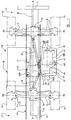
- The invention will now be described by way of example with reference to the accompanying diagrammatic drawings in which;
- FIGURE 1 is a fragmentary plan view, with parts omitted for clarity, of part of a telescopic loader vehicle embodying the invention,
- FIGURE 2 is a fragmentary side elevation, with parts omitted for clarity, of the vehicle of Figure 1,
- FIGURE 3 is a front end view, with parts omitted for clarity, of the vehicle of Figure 1,
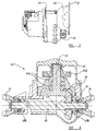
- FIGURE 4 is a fragmentary plan view, partly in section and to an enlarged scale, showing a transmission unit of the vehicle of Figure 1,
- FIGURE 5 is a side view of a gearbox and torque converter of a transmission unit for use in the vehicle of Figure 1,
- FIGURE 6 is an end view of the transmission unit of Figure 5 looking in the direction of the arrow A,
- FIGURE 7 is a side view of gearbox and torque converter parts of the transmission unit of Figure 5,
- FIGURE 8 is a section on the line 8-8 of Figure 6, and
- FIGURE 9 is a section on the line 9-9 of Figure 6.
-
- Referring to the Figures, a material-handling vehicle is indicated generally at 10 and comprises a main structure 11 having a
front end 12 and arear end 13 with a longitudinal axis X-X extending between the front and rear ends. The structure 11 comprises a pair of spacedparallel frame members - Each
frame member upper surface frame members upright parts hand frame member 15 has an upwardlyrelieved part 28 to provide clearance for an engine and a transmission unit as hereinafter to be described. - A
front axle 30 is mounted on theframe members rear axle 31 is mounted on theframe members axles front wheels 33 and rear wheels 34 respectively. Both thefront wheels 33 and both rear wheels 34 are pivotable relative to their associated axis about a steering axis V for steering movement of the vehicle, If desired at least one of the axles may be mounted relative to theframe members axle propeller shafts rear output couplings transmission unit 41. - The
transmission unit 41 incorporates a change speed gear train, shown in block diagrammatic form at 42, disposed in agear box 43, atorque converter 44 and an angle drive in anangle drive housing 45. If desired thetorque converter 44 may be omitted or other means for disconnecting drive when the vehicle is stationary may be provided, such as a mechanical clutch, for example, a friction clutch, or a fluid coupling. - The
gearbox 43 is, in the present example, a power shift gearbox where the gears and direction of rotation of the change speed gear train are selected by solenoid controlled hydraulically actuated clutch packs. If desired, the gearbox may be of a type where the gear or direction of rotation of the change speed gear train is mechanically selected or a combination of mechanical and clutch pack selection may be used. - The change speed gear train 42, as best shown in Figures 4 to 9, has an
output shaft 61a at the end thereof adjacent theangle drive housing 45, which has affixed, thereto to rotate therewith, a pinion 64a which meshes with apinion 64b splined to anintermediate shaft 65 which has afirst bevel gear 66 formed integrally therewith. Thebevel gear 66 meshes with asecond bevel gear 67 splined to ashaft 68 which is provided with the forward and rearward outputs 39, 40 respectively. Theoutputs torque converter 44 and so are disposed at the end of the transmission to be adjacent to the engine. Theshafts gearbox 43 bybearings shaft 65,first bevel gear 66,second bevel gear 67 andshaft 68 provide an input shaft, meshed gears and an output shaft, respectively of a further angle drive which in the present example is disposed in thehousing 45 which is part of the transmission unit. - The
gearbox 43 is disposed essentially between theframe members face 47 of theangle drive housing 45 is bolted to anopposed face 48 of anengine 49. A second mountingface 50 of the angle drive housing, disposed at right angles to theface 47, is bolted to an opposed mountingface 51 of thegearbox 43. - The
transmission unit 41 is mounted on theframe members first frame member 14, which is adjacent the operator's cab, and thegearbox 43. Asecond mount 46b is provided between thesecond frame member 15 and theangle drive housing 45. A third mounting 46c is provided between a part projecting transversely from theframe member 15 and theangle drive housing 45 on the opposite of the longitudinal axis of the engine to theframe member 15. Theengine 49 is supported in cantilever by virtue of the mountingface 48 of the engine being connected to the mountingface 47 of theangle drive housing 45. - The
torque converter 44 may be disposed wholly or partly in thegearbox 43 or in theangle drive housing 45 or may be provided partially in each thereof. Alternatively a separate housing may be provided for all or part of thetorque converter 44 appropriately disposed between thegearbox 43 and theangle drive housing 45. - The
engine 49 is, in the present example, a four cylinder engine having a crankshaft indicated diagrammatically at 52 which is rotatable about an axis which is parallel to the longitudinal axis X-X of the vehicle i.e. an axis which is midway between the ground engageable propulsion means on either side of the vehicle and which intersects the axis of rotation of the front and rear ground engageable propulsion means. Thecrankshaft 52 provides a drive shaft of the engine. - If desired the engine may be of other type such as a rotary engine such as a Wankel engine or a turbine. In this case of the rotor shaft or the turbine shaft respectively provides the drive shaft.
- Rotatably mounted within the
angle drive housing 45 is an angle drive which, as best shown in Figure 4, carries in suitable bearing means aninput shaft 53 which is connected via a vibration damper 54 to the engine output, provided in this example by aflywheel 55 on thedrive shaft 52. The angle drive also carries in suitable bearing means anoutput shaft 56 which is connected via thetorque converter 44 to aninput shaft 57 of the change speed gear train incorporated in thegearbox 43. The input andoutput shafts bevel gear 53a, 56a respectively fixed relative thereto, in the present example by being formed integrally therewith, and which are interengaged to transmit torque between the engine and the gearbox and to turn the direction of drive through 90° from a longitudinal direction to a transverse direction. - If desired, the first and second shafts may be formed separately from the input and output shafts and may be connected to them in any suitable manner. If desired, the input and output shafts may rotate about different axes to the first and second shafts and may be connected thereto by suitable gear means.
- The
output shaft 56 is connected by aquill shaft 58 to ahydraulic pump 59 bolted to thehousing 45. Alternatively, thehydraulic pump 59 may be orientated in the dotted line position shown in Figure 1 in which case the pump may be driven by the input bevel gear shaft. - Although in this example the
torque converter 44 is housed by virtue of thetransfer box 45 having an extension part 45a which provides a first torque converter housing part which cooperates with a second torque converter housing part 43a of thegearbox 43 to provide a housing for thetorque converter 44, if desired, the torque converter housing part may be separate from and bolted to thetransfer box 45. Moreover, the torque converter may be housed in any other desired manner so as to be operatively disposed between the change speed gear train and the angle drive or in another suitable disposition of the drive path such as between the engine and the angle drive or between the change speed gear train and the ground engaging propulsion means. - If desired, other forms of mechanical transfer means may be provided to transfer the drive between the engine and the gearbox.
- The engine is provided with a suitable cooling radiator but not shown. If desired this may be provided in the space to the rear of the engine above the
angle drive housing 45. - Although in the present example the
engine 49 is disposed substantially wholly to the front of a longitudinal midpoint between the axis RF and RR and the gearbox and transfer box substantially wholly to the rear of such midpoint, if desired, the engine may be disposed at any desired longitudinal position between the wheels and the gearbox may be positioned at a desired longitudinal position of the machine with a suitable spacing mechanism or connecting mechanism being provided between the engine and the angle drive housing where the angle drive is connected to the gearbox as described hereinbefore. Alternatively, suitable means may be provided to connect the output of the transfer box to the input of the gearbox where these components are longitudinally offset. - The distance between the outside of the
frame members range 27%-30%. - An operator's
cab 70 is mounted on theframe member 14 by vibration isolating mounts so that thecab 70 is supported on one side of the longitudinal axis X-X of the vehicle. Thecab 70 has a front window 77a, a rear window 77b and twoside windows 77c, 77d, the window 77c facing transversely across the machine. The or each window may be provided with a transparent closure element such as glass, or may be open, or may be provided with a protective element such as a grille or bars. A driver's seat, steering wheel S and other controls, not shown, are provided in the cab and the cab is provided with an access door or opening on the side in which thewindow 77d is provided. - A
loader arm 80, has a longitudinal axis L-L which lies in a vertical plane which is parallel to a vertical plane containing the longitudinal axis X-X of the vehicle and offset therefrom towards theengine 49. Thearm 80 is pivotally mounted, by means ofaxis member 81, between theframe members loader arm 80 is telescopic and comprises a rearouter section 82 which is pivotally connected to theframe members axis 81 and a forward inner member 87 which is telescopically slidable within thesection 82 under the control of hydraulic rams in conventional manner in the direction of the longitudinal axis L-L. At its front end thepart 83 is provided with a downwardly and forwardly extendingpart 84 adapted to carry a material handling implement such as a loader bucket or lifting forks or other desired material handling means. If desired the loader arm may have more than two telescopically slidable sections or may not be telescopic. If desired ram means for telescoping two or more sections may be disposed externally of the section. - When the
loader arm 80 is in its lowermost position, as shown in the figures, it lies in a well 90 of a minimum width which is slightly greater than the width of the loader arm, so as to provide a clearance therebetween. The well 90 is provided between thecab 70 and theframe member 15. In this lowermost position the arm is substantially horizontal but is inclined slightly downward in a forward direction. - The
internal combustion engine 49 is disposed on the opposite side of theframe member 15 to the well 90 and thus is disposed on the opposite side of the longitudinal axis X-X of the vehicle to thecab 70. - The engine is disposed in a
housing 85, the top 86a of which extends generally transversely away from theframe member 15 and is inclined generally forwardly and downwardly, as best shown in Figure 3. At its transversely outer side thehousing 85 has a generallyvertical side surface 86b and, front and rear end faces 86c, 86d respectively. If desired, the housing may be of a different configuration than that described hereinbefore and may be wholly or partly omitted. The top of the housing is below the top of the loader arm or any telescoping ram therefor so that the housing does not obstruct the view of an operator transversely over the loader arm. - The
engine 49 is so arranged that its crankshaft is parallel to the longitudinal axis X-X of the vehicle. - However, in another arrangement, if desired, the axis of rotation of the drive shaft of the engine may be arranged at an angle to the longitudinal axis X-X lying in the range +z° to -z° where z is 15° and preferably 10°. If desired the bevel gears 53a and 53b may be configured so as to maintain the axis of the gearbox at right angles to the longitudinal axis X-X whilst the axis of rotation of the drive shaft of the engine is varied as described above.
- In the present example the radiator is provided with an hydraulically operated fan, but if desired, it may be provided with an electrically or mechanically operated fan to cause flow of cooling air of the radiator, suitable ventilation openings may be provided in the housing 72 for flow of such air. If desired the radiator may be positioned at another position on the vehicle, such as adjacent to the rear thereof.
- The top of the
loader arm 80 in a fully lowered position and at a location alongside the top of a steering wheel in the operator's cab is disposed wholly or substantially wholly below a horizontal plane which is not more than 1 metre, or preferably not more than 0.5 metre above the top of the steering wheel so that the driver's vision is substantially unobstructed by the loader arm. If desired, and as in the present case the top of the boom at said position is wholly below a horizontal plane containing the top of the steering wheel. - The loader arm in its lowered position may be horizontal or may extend forwardly and downwardly.
- The loader arm may be telescopic in the direction of the longitudinal axis of the loader arm.
- The longitudinal axis of the loader arm may in a substantially horizontal plane when the loader arm is in a position in which the implement engages a horizontal plane on which the ground engageable propulsion means are supported and, if the loader arm is telescopic, the loader arm is fully retracted.
- In the specification by "substantially horizontal" we mean that the longitudinal axis is either in a horizontal plane or is in a plane which is inclined upwardly or downwardly to the horizontal at an angle lying the in the range of +5° to -25°.
- The engine may be disposed so that at least a major portion of the engine is situated below a plane tangent to the top of the ground engaging propulsion means so as not to interfere with the view of an operator working in the operator's cab.
- If desired, the wheels on the front axle may have a different track to the wheels of the rear axle.
- If desired the ground engageable propulsion means may comprise endless tracks entrained about front and rear wheels in conventional manner.
- By a "longitudinal axis of the vehicle" we mean an axis which passes through a mid point of the front wheel track and the rear wheel track of the vehicle.
- The differential may be positioned on the front and rear axle as desired in order to minimise the respective propeller shaft angle.
- Although in this specification the angle drive, torque converter, change speed gear train, and further angle drive have all been described as being disposed in a multi-part housing in which the parts are rigidly connected together to form a unitary transmission unit, if desired the unitary transmission unit housing may be made of a desired number of parts and may contain all the above mentioned components or one or other desired number of said components. The or each component not included in the transmission unit may be provided each as a separate unit or may be provided as a further transmission unit or units.
- Although in the above example the engine has been described as having a crankshaft which lies parallel to the longitudinal axis of the vehicle and the gearbox as having an input shaft and an output shaft which lie at 90° to the longitudinal axis of the vehicle, it may be desired to orientate the engine or the gearbox at angles inclined to those mentioned above for example for improved access or to reduce drive shaft angle.
- Accordingly in this specification the term "longitudinal" is used to mean a direction which is parallel to a vertical plane containing the longitudinal axis of the vehicle or a direction which inclined relative to said direction at an angle lying in the range of +x° to -x° and the term "transverse" is used to mean to a direction which is inclined at 90° to a vertical plane containing the longitudinal axis of the vehicle or which is inclined relative to said direction at an angle lying in the range +y° to -y° where x = 15° and preferably 10° and y = 15° or preferably 10°.
- Although in the present example the engine is a reciprocatory engine having a crankshaft to provide the shaft, the engine may be a rotary engine such as a Wankel engine or a turbine, the rotor or turbine of which is mounted on a drive shaft of the engine.
- Whilst in the example described the angle drive has comprised an input shaft and an output shaft mutually inclined at 90° and kinematically, mechanically or hydrostatically connected by gears the term "angle drive" is used herein to mean a drive having an input shaft and an output shaft which are kinematically connected in any suitable way for example mechanically or hydrostatically and which are mutually inclined at any desired angle.
- In the present specification "comprise" means "includes or consists of" and "comprising" means "including or consisting of".
- The features disclosed in the foregoing description, or the following claims, or the accompanying drawings, expressed in their specific forms or in terms of a means for performing the disclosed function, or a method or process for attaining the disclosed result, as appropriate, may, separately, or in any combination of such features, be utilised for realising the invention in diverse forms thereof.
Claims (28)
- A material handling vehicle including a structure having ground engageable propulsion means, a loader arm mounted on the structure for up and down swinging movement and, on opposite sides of the loader arm, an operator's cab and an engine having an output to provide power for said movement of the loader arm and for propulsion of the vehicle and a drive to connect the output of the engine to the ground engageable propulsion means to propel the vehicle, wherein the drive includes an angle drive and a change speed gear train, the output of the engine is kinematically connected to an input of the angle drive and an output of the angle drive is kinematically connected to an input of the change speed gear train, and an output of the change speed gear train is kinematically connected to the ground engageable propulsion means wherein the output of the engine and the input of the angle drive are disposed longitudinally of the vehicle whilst the output of the angle drive is disposed transversely of the vehicle.
- A vehicle according to Claim 1 wherein the input of the change speed gear is disposed transversely of the vehicle and the output of the change gear train is disposed transversely of the vehicle.
- A vehicle according to Claim 1 or Claim 2 wherein the drive means includes means for disconnecting the drive between the engine and the ground engageable propulsion means.
- A vehicle according to Claim 3 wherein said disconnecting means is disposed between the engine and the angle drive.
- A vehicle according to any preceding claim wherein the engine has a drive shaft which is disposed longitudinally of the vehicle.
- A vehicle according to any preceding claim wherein the change speed gear train is disposed in a housing comprising a gearbox.
- A vehicle according to any one of the preceding claims wherein the angle drive and the change speed gear train are disposed in at least one housing, said at least one housing comprising a transmission unit.
- A vehicle according to any one of the preceding claims wherein the vehicle comprises a chassis having a pair of spaced longitudinally extending frame members.
- A vehicle according to Claim 7 or Claim 8 when dependent on Claim 7, wherein the transmission unit is provided with at least one output which is kinematically connected to said ground engageable propulsion means.
- A vehicle according to Claim 9 wherein the at least one output is disposed on or parallel to a longitudinal axis of the vehicle.
- A vehicle according to Claim 9 or Claim 10 wherein the transmission unit has a front output and a rear output.
- A vehicle according to Claim 11 wherein said outputs of the transmission units are provided at opposite ends of a shaft, which is driven by the output of the change speed gear train, and which is disposed longitudinally of the vehicle.
- A vehicle according to any one of the preceding claims wherein the output of the change speed gear train is connected to an input of a further angle drive having an output which extends longitudinally of the vehicle.
- A vehicle according to any one of Claims 9 to 13 wherein the output of the change speed gear train is connected to an input of a further angle drive having an output which is kinematically connected to said output of the transmission unit.
- A vehicle according to Claim 13 or Claim 14 wherein the output of the further angle drive is disposed adjacent the engine.
- A vehicle according to Claim 15 wherein the further angle drive is disposed adjacent the engine.
- A vehicle according to Claim 9 or any one of Claims 10 to 16 when dependent on Claim 9 wherein a vehicle comprises a front axle and a rear axle each having a ground engageable propulsion means and the propulsion means of at least one of said axles being connected to said at least one output of the transmission unit.
- A vehicle according to Claim 8 or any one of Claims 10 to 17 when dependent on Claim 8 wherein the change speed gear train is disposed substantially within the chassis frame members and between axes of rotation of front and rear ground engageable propulsion means.
- A vehicle according to any one of the preceding claims wherein the engine is spaced from the cab to define a well between the cab and the engine in which the arm, in a lowered position, can be at least partly accommodated.
- A vehicle according to Claim 19 when dependent on Claim 8 or on any one of Claims 9 to 18 when dependent on Claim 8 wherein the well is disposed between the chassis frame member.
- A vehicle according to Claim 7 or any one of Claims 8 to 20 when dependent on Claim 7 wherein mounting means are provided between the structure and at least one of the engine and transmission unit.
- A vehicle according to Claim 21 wherein mounting means are provided between the structure and the transmission unit and the engine is carried by the transmission unit.
- A vehicle according to any preceding claim wherein the engine, angle drive housing and change speed gearbox are rigidly connected together.
- A vehicle according to any one of the preceding claims wherein the angle drive comprises first and second shafts disposed at an angle to each other, the first shaft being connected to or comprising the input shaft of the angle drive and the second shaft being connected to or comprising the output of the angle drive and the first and second shafts being connectable in torque transmitting relationship.
- A vehicle according to Claim 24 wherein said first and second shafts are connectable in said torque transmitting relationship by a bevel gear set.
- A vehicle according to any one of the preceding claims wherein the angle drive comprises a first bevel gear mounted for rotation about an axis which extends longitudinally of the vehicle and which is in mesh with a second bevel gear which is mounted for rotation about an axis which extends transversely of the vehicle.
- A vehicle according to any one of the preceding claims wherein at lease one pump for hydraulic fluid is either transversely and/or longitudinally disposed so as to be driven by transversely and/or longitudinally disposed shafts of the angle drive.
- A vehicle according to any one of the preceding claims wherein a cooling radiator is disposed above the angle drive.
Applications Claiming Priority (2)
| Application Number | Priority Date | Filing Date | Title |
|---|---|---|---|
| GB9921800 | 1999-09-16 | ||
| GBGB9921800.0A GB9921800D0 (en) | 1999-09-16 | 1999-09-16 | Material -handling vehicle |
Publications (2)
| Publication Number | Publication Date |
|---|---|
| EP1084986A1 true EP1084986A1 (en) | 2001-03-21 |
| EP1084986B1 EP1084986B1 (en) | 2004-12-29 |
Family
ID=10860957
Family Applications (1)
| Application Number | Title | Priority Date | Filing Date |
|---|---|---|---|
| EP00119916A Expired - Lifetime EP1084986B1 (en) | 1999-09-16 | 2000-09-13 | Material-handling vehicle |
Country Status (6)
| Country | Link |
|---|---|
| US (1) | US6382899B1 (en) |
| EP (1) | EP1084986B1 (en) |
| AT (1) | ATE285982T1 (en) |
| DE (1) | DE60017036T2 (en) |
| ES (1) | ES2232365T3 (en) |
| GB (2) | GB9921800D0 (en) |
Cited By (6)
| Publication number | Priority date | Publication date | Assignee | Title |
|---|---|---|---|---|
| EP1362824A1 (en) * | 2002-05-15 | 2003-11-19 | Komatsu Utility Europe S.p.A. | Lifting vehicle with a telescopic lifting arm |
| EP1312498A3 (en) * | 2001-11-16 | 2004-05-26 | Caterpillar Inc. | Horizontal transmission and oil system for telehandlers |
| IT201900004839A1 (en) * | 2019-04-01 | 2020-10-01 | Dieci S R L | VEHICLE FOR HANDLING LOADS |
| IT201900004845A1 (en) * | 2019-04-01 | 2020-10-01 | Dieci S R L | VEHICLE FOR HANDLING LOADS |
| IT201900004833A1 (en) * | 2019-04-01 | 2020-10-01 | Dieci S R L | VEHICLE FOR HANDLING LOADS |
| EP3702312B1 (en) | 2019-03-01 | 2023-12-13 | J.C. Bamford Excavators Limited | Working machine |
Families Citing this family (7)
| Publication number | Priority date | Publication date | Assignee | Title |
|---|---|---|---|---|
| JP4553447B2 (en) * | 2000-04-26 | 2010-09-29 | 本田技研工業株式会社 | Rough terrain vehicle |
| FR2884459B1 (en) * | 2005-04-14 | 2008-09-19 | Peugeot Citroen Automobiles Sa | HYBRID TRACTION CHAIN AND HYBRID VEHICLE EQUIPPED WITH SUCH A HYBRID TRACTION CHAIN |
| US20080271940A1 (en) * | 2007-05-04 | 2008-11-06 | De Craemer Thomas M M | Transmission system for a vehicle |
| GB2470739A (en) * | 2009-06-02 | 2010-12-08 | Redrock Engineering Ltd | Telehandler vehicle having improved drive train layout |
| DE102018115036A1 (en) * | 2018-06-22 | 2019-12-24 | Weidemann GmbH | Work vehicle with electrical energy storage |
| GB2623565B8 (en) * | 2022-10-20 | 2025-07-23 | Bamford Excavators Ltd | A material handling machine |
| FR3148395A1 (en) * | 2023-05-03 | 2024-11-08 | Manitou Bf | Working machine comprising a removable power supply unit |
Citations (3)
| Publication number | Priority date | Publication date | Assignee | Title |
|---|---|---|---|---|
| EP0656315A1 (en) * | 1993-12-01 | 1995-06-07 | Manitou Bf | Forklift truck with telescopic arm |
| EP0692448A1 (en) * | 1994-07-15 | 1996-01-17 | J.C. Bamford Excavators Limited | Material-handling vehicle |
| US5707202A (en) * | 1994-05-16 | 1998-01-13 | Caterpillar Inc. | Material handling machine |
Family Cites Families (8)
| Publication number | Priority date | Publication date | Assignee | Title |
|---|---|---|---|---|
| DE240869C (en) | ||||
| US2257772A (en) * | 1932-04-07 | 1941-10-07 | Austin M Wolf | Motor vehicle propulsion |
| GB1127922A (en) * | 1964-10-20 | 1968-09-18 | Ferguson Res Ltd Harry | Improvements in or relating to motor vehicle drive arrangements |
| IT212207Z2 (en) | 1987-07-27 | 1989-07-04 | Merlo Ind Metalmecc | TELESCOPIC ARM FORKLIFT |
| CA2009968C (en) | 1990-02-13 | 1996-06-25 | Giovanni Bentivoglio | Boom operated fork truck |
| GB2268155B (en) | 1992-06-30 | 1996-10-02 | Artix Ltd | Material handling machine |
| GB2317598B (en) * | 1996-09-26 | 2000-10-25 | Multidrive Ltd | Truck |
| GB9807530D0 (en) * | 1998-04-09 | 1998-06-10 | Bamford Excavators Ltd | Material-handling vehicle |
-
1999
- 1999-09-16 GB GBGB9921800.0A patent/GB9921800D0/en not_active Ceased
-
2000
- 2000-09-07 GB GB0021960A patent/GB2354212B/en not_active Expired - Lifetime
- 2000-09-13 EP EP00119916A patent/EP1084986B1/en not_active Expired - Lifetime
- 2000-09-13 DE DE60017036T patent/DE60017036T2/en not_active Expired - Lifetime
- 2000-09-13 AT AT00119916T patent/ATE285982T1/en not_active IP Right Cessation
- 2000-09-13 ES ES00119916T patent/ES2232365T3/en not_active Expired - Lifetime
- 2000-09-14 US US09/661,868 patent/US6382899B1/en not_active Expired - Lifetime
Patent Citations (4)
| Publication number | Priority date | Publication date | Assignee | Title |
|---|---|---|---|---|
| EP0656315A1 (en) * | 1993-12-01 | 1995-06-07 | Manitou Bf | Forklift truck with telescopic arm |
| US5707202A (en) * | 1994-05-16 | 1998-01-13 | Caterpillar Inc. | Material handling machine |
| EP0692448A1 (en) * | 1994-07-15 | 1996-01-17 | J.C. Bamford Excavators Limited | Material-handling vehicle |
| US5836733A (en) * | 1994-07-15 | 1998-11-17 | J.C. Bamford Excavators Limited | Material-handling vehicle |
Cited By (11)
| Publication number | Priority date | Publication date | Assignee | Title |
|---|---|---|---|---|
| EP1312498A3 (en) * | 2001-11-16 | 2004-05-26 | Caterpillar Inc. | Horizontal transmission and oil system for telehandlers |
| US6904994B2 (en) | 2001-11-16 | 2005-06-14 | Caterpillar Inc | Horizontal transmission and oil system for telehandlers |
| EP1362824A1 (en) * | 2002-05-15 | 2003-11-19 | Komatsu Utility Europe S.p.A. | Lifting vehicle with a telescopic lifting arm |
| EP3702312B1 (en) | 2019-03-01 | 2023-12-13 | J.C. Bamford Excavators Limited | Working machine |
| EP4310046A3 (en) * | 2019-03-01 | 2024-05-01 | J.C. Bamford Excavators Limited | Working machine |
| IT201900004839A1 (en) * | 2019-04-01 | 2020-10-01 | Dieci S R L | VEHICLE FOR HANDLING LOADS |
| IT201900004845A1 (en) * | 2019-04-01 | 2020-10-01 | Dieci S R L | VEHICLE FOR HANDLING LOADS |
| IT201900004833A1 (en) * | 2019-04-01 | 2020-10-01 | Dieci S R L | VEHICLE FOR HANDLING LOADS |
| EP3718952A1 (en) * | 2019-04-01 | 2020-10-07 | Dieci S.r.l. | Vehicle for load handling |
| EP3718954A1 (en) * | 2019-04-01 | 2020-10-07 | Dieci S.r.l. | Vehicle for load handling |
| EP3718953A1 (en) * | 2019-04-01 | 2020-10-07 | Dieci S.r.l. | Vehicle for load handling |
Also Published As
| Publication number | Publication date |
|---|---|
| US6382899B1 (en) | 2002-05-07 |
| GB2354212A (en) | 2001-03-21 |
| DE60017036D1 (en) | 2005-02-03 |
| GB9921800D0 (en) | 1999-11-17 |
| ES2232365T3 (en) | 2005-06-01 |
| GB0021960D0 (en) | 2000-10-25 |
| ATE285982T1 (en) | 2005-01-15 |
| DE60017036T2 (en) | 2005-06-16 |
| GB2354212B (en) | 2002-09-25 |
| EP1084986B1 (en) | 2004-12-29 |
Similar Documents
| Publication | Publication Date | Title |
|---|---|---|
| US5836733A (en) | Material-handling vehicle | |
| EP1084986B1 (en) | Material-handling vehicle | |
| EP0949187A2 (en) | Material-handling vehicle | |
| US6514031B1 (en) | Material-handling vehicle | |
| EP0876932B1 (en) | Power transfer arrangement for a machine | |
| US6554558B2 (en) | Material-handling vehicle | |
| GB2291384A (en) | Material-handling vehicle with a loader arm and transverse engine | |
| EP1348889B1 (en) | Material handling vehicle transmission | |
| EP1312498B1 (en) | Horizontal transmission and oil system for telehandlers | |
| US6079937A (en) | Material-handling vehicle | |
| EP0949186A2 (en) | Material-handling vehicle | |
| GB2289656A (en) | Drive arrangement for a material handling vehicle | |
| JP4323000B2 (en) | Work vehicle | |
| EP0945396A2 (en) | A vehicle with a lifting boom, having an engine inclined with respect to the longitudinal axis of the vehicle | |
| JPH057032U (en) | Mower Tractor Mt Mount Mower Drive Unit | |
| JP2021104776A (en) | Service car | |
| JPH06211061A (en) | Work vehicle | |
| RU98112728A (en) | TRANCHED TRACKED MACHINE | |
| JP2535023B2 (en) | HST type traveling transmission | |
| JP2001105895A (en) | Wheel type work vehicle | |
| RU8325U1 (en) | HIGH PERFORMANCE VEHICLE (OPTIONS) | |
| JPH0647339B2 (en) | Mounting mechanism of the Mitumount work machine | |
| JPH02119637A (en) | Power taking out mechanism for working machine |
Legal Events
| Date | Code | Title | Description |
|---|---|---|---|
| PUAI | Public reference made under article 153(3) epc to a published international application that has entered the european phase |
Free format text: ORIGINAL CODE: 0009012 |
|
| AK | Designated contracting states |
Kind code of ref document: A1 Designated state(s): AT BE CH CY DE DK ES FI FR GB GR IE IT LI LU MC NL PT SE |
|
| AX | Request for extension of the european patent |
Free format text: AL;LT;LV;MK;RO;SI |
|
| 17P | Request for examination filed |
Effective date: 20010920 |
|
| AKX | Designation fees paid |
Free format text: AT BE CH CY DE DK ES FI FR GB GR IE IT LI LU MC NL PT SE |
|
| GRAP | Despatch of communication of intention to grant a patent |
Free format text: ORIGINAL CODE: EPIDOSNIGR1 |
|
| GRAS | Grant fee paid |
Free format text: ORIGINAL CODE: EPIDOSNIGR3 |
|
| GRAA | (expected) grant |
Free format text: ORIGINAL CODE: 0009210 |
|
| AK | Designated contracting states |
Kind code of ref document: B1 Designated state(s): AT BE CH CY DE DK ES FI FR GB GR IE IT LI LU MC NL PT SE |
|
| PG25 | Lapsed in a contracting state [announced via postgrant information from national office to epo] |
Ref country code: AT Free format text: LAPSE BECAUSE OF FAILURE TO SUBMIT A TRANSLATION OF THE DESCRIPTION OR TO PAY THE FEE WITHIN THE PRESCRIBED TIME-LIMIT Effective date: 20041229 Ref country code: CH Free format text: LAPSE BECAUSE OF FAILURE TO SUBMIT A TRANSLATION OF THE DESCRIPTION OR TO PAY THE FEE WITHIN THE PRESCRIBED TIME-LIMIT Effective date: 20041229 Ref country code: LI Free format text: LAPSE BECAUSE OF FAILURE TO SUBMIT A TRANSLATION OF THE DESCRIPTION OR TO PAY THE FEE WITHIN THE PRESCRIBED TIME-LIMIT Effective date: 20041229 Ref country code: FI Free format text: LAPSE BECAUSE OF FAILURE TO SUBMIT A TRANSLATION OF THE DESCRIPTION OR TO PAY THE FEE WITHIN THE PRESCRIBED TIME-LIMIT Effective date: 20041229 |
|
| REG | Reference to a national code |
Ref country code: GB Ref legal event code: FG4D |
|
| REG | Reference to a national code |
Ref country code: CH Ref legal event code: EP |
|
| RBV | Designated contracting states (corrected) |
Designated state(s): AT BE CH CY DE DK ES FI FR GR IE IT LI LU MC NL PT SE |
|
| REG | Reference to a national code |
Ref country code: IE Ref legal event code: FG4D |
|
| REF | Corresponds to: |
Ref document number: 60017036 Country of ref document: DE Date of ref document: 20050203 Kind code of ref document: P |
|
| PG25 | Lapsed in a contracting state [announced via postgrant information from national office to epo] |
Ref country code: DK Free format text: LAPSE BECAUSE OF FAILURE TO SUBMIT A TRANSLATION OF THE DESCRIPTION OR TO PAY THE FEE WITHIN THE PRESCRIBED TIME-LIMIT Effective date: 20050329 Ref country code: GR Free format text: LAPSE BECAUSE OF FAILURE TO SUBMIT A TRANSLATION OF THE DESCRIPTION OR TO PAY THE FEE WITHIN THE PRESCRIBED TIME-LIMIT Effective date: 20050329 |
|
| REG | Reference to a national code |
Ref country code: SE Ref legal event code: TRGR |
|
| REG | Reference to a national code |
Ref country code: ES Ref legal event code: FG2A Ref document number: 2232365 Country of ref document: ES Kind code of ref document: T3 |
|
| REG | Reference to a national code |
Ref country code: CH Ref legal event code: PL |
|
| PG25 | Lapsed in a contracting state [announced via postgrant information from national office to epo] |
Ref country code: CY Free format text: LAPSE BECAUSE OF FAILURE TO SUBMIT A TRANSLATION OF THE DESCRIPTION OR TO PAY THE FEE WITHIN THE PRESCRIBED TIME-LIMIT Effective date: 20050913 |
|
| PG25 | Lapsed in a contracting state [announced via postgrant information from national office to epo] |
Ref country code: LU Free format text: LAPSE BECAUSE OF NON-PAYMENT OF DUE FEES Effective date: 20050930 Ref country code: MC Free format text: LAPSE BECAUSE OF NON-PAYMENT OF DUE FEES Effective date: 20050930 |
|
| PLBE | No opposition filed within time limit |
Free format text: ORIGINAL CODE: 0009261 |
|
| STAA | Information on the status of an ep patent application or granted ep patent |
Free format text: STATUS: NO OPPOSITION FILED WITHIN TIME LIMIT |
|
| 26N | No opposition filed |
Effective date: 20050930 |
|
| ET | Fr: translation filed | ||
| PG25 | Lapsed in a contracting state [announced via postgrant information from national office to epo] |
Ref country code: PT Free format text: LAPSE BECAUSE OF NON-PAYMENT OF DUE FEES Effective date: 20050529 |
|
| REG | Reference to a national code |
Ref country code: FR Ref legal event code: PLFP Year of fee payment: 17 |
|
| REG | Reference to a national code |
Ref country code: FR Ref legal event code: PLFP Year of fee payment: 18 |
|
| REG | Reference to a national code |
Ref country code: FR Ref legal event code: PLFP Year of fee payment: 19 |
|
| PGFP | Annual fee paid to national office [announced via postgrant information from national office to epo] |
Ref country code: SE Payment date: 20190918 Year of fee payment: 20 Ref country code: FR Payment date: 20190925 Year of fee payment: 20 Ref country code: NL Payment date: 20190918 Year of fee payment: 20 Ref country code: IT Payment date: 20190925 Year of fee payment: 20 Ref country code: IE Payment date: 20190919 Year of fee payment: 20 Ref country code: DE Payment date: 20190918 Year of fee payment: 20 |
|
| PGFP | Annual fee paid to national office [announced via postgrant information from national office to epo] |
Ref country code: BE Payment date: 20190918 Year of fee payment: 20 |
|
| PGFP | Annual fee paid to national office [announced via postgrant information from national office to epo] |
Ref country code: ES Payment date: 20191022 Year of fee payment: 20 |
|
| REG | Reference to a national code |
Ref country code: DE Ref legal event code: R071 Ref document number: 60017036 Country of ref document: DE |
|
| REG | Reference to a national code |
Ref country code: NL Ref legal event code: MK Effective date: 20200912 |
|
| REG | Reference to a national code |
Ref country code: BE Ref legal event code: MK Effective date: 20200913 |
|
| REG | Reference to a national code |
Ref country code: IE Ref legal event code: MK9A |
|
| PG25 | Lapsed in a contracting state [announced via postgrant information from national office to epo] |
Ref country code: IE Free format text: LAPSE BECAUSE OF EXPIRATION OF PROTECTION Effective date: 20200913 Ref country code: ES Free format text: LAPSE BECAUSE OF EXPIRATION OF PROTECTION Effective date: 20200914 |