EP1084889B1 - Tank insert and method for its manufacturing - Google Patents
Tank insert and method for its manufacturing Download PDFInfo
- Publication number
- EP1084889B1 EP1084889B1 EP00117409A EP00117409A EP1084889B1 EP 1084889 B1 EP1084889 B1 EP 1084889B1 EP 00117409 A EP00117409 A EP 00117409A EP 00117409 A EP00117409 A EP 00117409A EP 1084889 B1 EP1084889 B1 EP 1084889B1
- Authority
- EP
- European Patent Office
- Prior art keywords
- insert
- thermoplastic material
- tank
- connection
- fuel tank
- Prior art date
- Legal status (The legal status is an assumption and is not a legal conclusion. Google has not performed a legal analysis and makes no representation as to the accuracy of the status listed.)
- Expired - Lifetime
Links
Images


Classifications
-
- B—PERFORMING OPERATIONS; TRANSPORTING
- B60—VEHICLES IN GENERAL
- B60K—ARRANGEMENT OR MOUNTING OF PROPULSION UNITS OR OF TRANSMISSIONS IN VEHICLES; ARRANGEMENT OR MOUNTING OF PLURAL DIVERSE PRIME-MOVERS IN VEHICLES; AUXILIARY DRIVES FOR VEHICLES; INSTRUMENTATION OR DASHBOARDS FOR VEHICLES; ARRANGEMENTS IN CONNECTION WITH COOLING, AIR INTAKE, GAS EXHAUST OR FUEL SUPPLY OF PROPULSION UNITS IN VEHICLES
- B60K15/00—Arrangement in connection with fuel supply of combustion engines or other fuel consuming energy converters, e.g. fuel cells; Mounting or construction of fuel tanks
- B60K15/03—Fuel tanks
- B60K15/035—Fuel tanks characterised by venting means
- B60K15/03519—Valve arrangements in the vent line
-
- B—PERFORMING OPERATIONS; TRANSPORTING
- B60—VEHICLES IN GENERAL
- B60K—ARRANGEMENT OR MOUNTING OF PROPULSION UNITS OR OF TRANSMISSIONS IN VEHICLES; ARRANGEMENT OR MOUNTING OF PLURAL DIVERSE PRIME-MOVERS IN VEHICLES; AUXILIARY DRIVES FOR VEHICLES; INSTRUMENTATION OR DASHBOARDS FOR VEHICLES; ARRANGEMENTS IN CONNECTION WITH COOLING, AIR INTAKE, GAS EXHAUST OR FUEL SUPPLY OF PROPULSION UNITS IN VEHICLES
- B60K15/00—Arrangement in connection with fuel supply of combustion engines or other fuel consuming energy converters, e.g. fuel cells; Mounting or construction of fuel tanks
- B60K15/03—Fuel tanks
- B60K15/03177—Fuel tanks made of non-metallic material, e.g. plastics, or of a combination of non-metallic and metallic material
-
- B—PERFORMING OPERATIONS; TRANSPORTING
- B60—VEHICLES IN GENERAL
- B60K—ARRANGEMENT OR MOUNTING OF PROPULSION UNITS OR OF TRANSMISSIONS IN VEHICLES; ARRANGEMENT OR MOUNTING OF PLURAL DIVERSE PRIME-MOVERS IN VEHICLES; AUXILIARY DRIVES FOR VEHICLES; INSTRUMENTATION OR DASHBOARDS FOR VEHICLES; ARRANGEMENTS IN CONNECTION WITH COOLING, AIR INTAKE, GAS EXHAUST OR FUEL SUPPLY OF PROPULSION UNITS IN VEHICLES
- B60K15/00—Arrangement in connection with fuel supply of combustion engines or other fuel consuming energy converters, e.g. fuel cells; Mounting or construction of fuel tanks
- B60K15/03—Fuel tanks
- B60K2015/03032—Manufacturing of fuel tanks
- B60K2015/03046—Manufacturing of fuel tanks made from more than one layer
-
- B—PERFORMING OPERATIONS; TRANSPORTING
- B60—VEHICLES IN GENERAL
- B60K—ARRANGEMENT OR MOUNTING OF PROPULSION UNITS OR OF TRANSMISSIONS IN VEHICLES; ARRANGEMENT OR MOUNTING OF PLURAL DIVERSE PRIME-MOVERS IN VEHICLES; AUXILIARY DRIVES FOR VEHICLES; INSTRUMENTATION OR DASHBOARDS FOR VEHICLES; ARRANGEMENTS IN CONNECTION WITH COOLING, AIR INTAKE, GAS EXHAUST OR FUEL SUPPLY OF PROPULSION UNITS IN VEHICLES
- B60K15/00—Arrangement in connection with fuel supply of combustion engines or other fuel consuming energy converters, e.g. fuel cells; Mounting or construction of fuel tanks
- B60K15/03—Fuel tanks
- B60K2015/03328—Arrangements or special measures related to fuel tanks or fuel handling
- B60K2015/03447—Arrangements or special measures related to fuel tanks or fuel handling for improving the sealing
-
- B—PERFORMING OPERATIONS; TRANSPORTING
- B60—VEHICLES IN GENERAL
- B60K—ARRANGEMENT OR MOUNTING OF PROPULSION UNITS OR OF TRANSMISSIONS IN VEHICLES; ARRANGEMENT OR MOUNTING OF PLURAL DIVERSE PRIME-MOVERS IN VEHICLES; AUXILIARY DRIVES FOR VEHICLES; INSTRUMENTATION OR DASHBOARDS FOR VEHICLES; ARRANGEMENTS IN CONNECTION WITH COOLING, AIR INTAKE, GAS EXHAUST OR FUEL SUPPLY OF PROPULSION UNITS IN VEHICLES
- B60K15/00—Arrangement in connection with fuel supply of combustion engines or other fuel consuming energy converters, e.g. fuel cells; Mounting or construction of fuel tanks
- B60K15/03—Fuel tanks
- B60K2015/03328—Arrangements or special measures related to fuel tanks or fuel handling
- B60K2015/03453—Arrangements or special measures related to fuel tanks or fuel handling for fixing or mounting parts of the fuel tank together
- B60K2015/03467—Arrangements or special measures related to fuel tanks or fuel handling for fixing or mounting parts of the fuel tank together by clip or snap fit fittings
Abstract
Description
Die Erfindung betrifft einen Einsatz aus thermoplastischem Material zur Verbindung mit einem Hohlkörper aus thermoplastischem Material, insbesondere als eine Anschlußöffnung eines Kraftstofftanks auskleindendes und/oder einen Sitz für ein Anschlußelement bildendes Bauteil. Ein solcher Einsatz ist aus dem gattungsbildenden Dokument US-A-5 404 907 bekannt.The invention relates to an insert made of thermoplastic Material for connection to a hollow body made of thermoplastic Material, especially as a connection opening of a Fuel tank lining and / or a seat for one Component forming the connecting element. Such use is over the generic document US-A-5 404 907 is known.
Als Anschlußelemente kommen beispielsweise Ventile, Anschlußstutzen sowie Nippel in Betracht. Weiterhin kann eine Anschlußöffnung des Tanks zur Aufnahme einer Fördereinheit oder als sogenannte Geberöffnung (Füllstandsanzeige) oder auch als Einführrohranschluß ausgebildet sein.Valves and connecting pieces, for example, come as connection elements as well as nipples. Furthermore, a Connection opening of the tank to accommodate a conveyor unit or as a so-called transmitter opening (level indicator) or also be designed as an insertion tube connection.
An Kraftstofftanks sind erhöhte Anforderungen an deren Durchlässigkeit für Kohlenwasserstoffe zu stellen. Nach neuesten Umweltvorschriften darf die Gesamtkohlenwasserstoff-Emission eines abgestellten Fahrzeugs nicht mehr als 0,5 g in 24 Stunden betragen. Entsprechend hohe Anforderungen sind an die maximale Kohlenwasserstoff-Emission eines Kraftstofftank-Systems zu stellen. Aus diesem Grunde ist es bekannt, Kraftstofftanks im Co-Extrusions-Blasverfahren herzustellen, wobei deren Wandung aus einem Laminat mit einer oder mehreren für Kohlenwasserstoffe schwer permeablen Barriereschichten besteht. Solche Tanks genügen im allgemeinen den erhöhten Anforderungen im Bezug auf maximal zulässige Kohlenwasserstoff-Emissionen. There are increased requirements for their permeability to fuel tanks to provide for hydrocarbons. According to the latest Total hydrocarbon emissions are allowed by environmental regulations of a parked vehicle not more than 0.5 g in 24 hours be. Correspondingly high demands are made on the maximum hydrocarbon emissions from a fuel tank system to deliver. Because of this, it is known to use fuel tanks to produce in the co-extrusion blow molding process, wherein the wall of which is made of a laminate with one or more for There are hydrocarbon-difficult permeable barrier layers. Such tanks generally meet the increased requirements in terms of maximum permissible hydrocarbon emissions.
In dieser Hinsicht problematisch sind jedoch Anschlußöffnungen im Tank, die einen Dichtsitz für Stutzen, Ventile und dergleichen bilden. Da soche Anschlußöffnungen eng toleriert sein müssen, um beispielsweise einen hinreichend dichtenden und spielfreien Sitz eines Anschlußstutzens oder eines Ventils zu gewährleisten, ist es in vielen Fällen nicht möglich, den Ventilsitz bzw. Dichtsitz für das Anschlußbauteil in einem Arbeitsgang bei der Herstellung (Extrusionsblasen) des Tanks mit vorzusehen.However, connection openings are problematic in this respect in the tank, which has a sealing seat for nozzles, valves and the like form. Since such openings are closely tolerated have to, for example, a sufficiently sealing and play-free seat of a connecting piece or a valve guarantee, it is not possible in many cases Valve seat or sealing seat for the connection component in one Operation in the manufacture (extrusion blow molding) of the tank to provide with.
In dem Tank wird daher als Anschlußöffnung eine Öffnung vorgesehen. Es gibt nun verschiedene Möglichkeiten, beispielsweise ein Ventil dichtend in diese Öffnung einzusetzen. Einerseits besteht die Möglichkeit, das Ventil mittels gegen die Tankwandung anliegender Dichtungen gegen die Tankwand zu verschrauben. Diese Maßnahme ist für Kraftstofftanks wegen erhöhter Dichtigkeitsanforderungen an den Tank ungeeignet. Ein Verschweißen des Ventils mit dem Tank kommt ohne weiteres ebenfalls nicht in Betracht, da Ventile und Anschlußstutzen in der Regel insbesondere wegen der Kraftstoffbeständigkeit des Materials aus POM (Polyoximethylen) bestehen, wohingegen der Tank zumindest teilweise aus PE (Polyethylen) besteht; die verschiedenen Materialien sind nicht miteinander verschweißbar.An opening is therefore provided in the tank as a connection opening. There are now several options, for example insert a valve sealingly into this opening. On the one hand there is the possibility of using the valve against the Screw the tank wall of adjacent seals against the tank wall. This measure is increased for fuel tanks Tightness requirements for the tank unsuitable. On Welding the valve to the tank is straightforward also not considered, since valves and connecting pieces in generally because of the fuel resistance of the Materials are made of POM (polyoxymethylene), whereas the Tank is at least partially made of PE (polyethylene); the different materials cannot be welded together.
Deswegen werden aus POM bestehende Ventile oder Nippel mit einem aus PE gespritzten Schaft versehen, in welchen das Ventil oder der Anschlußnippel eingeclipst werden. Der Schaft kann dann im Bereich der Anschlußöffnung des Tanks mit diesem verschweißt werden, beispielsweise im Heizelement-Schweißverfahren. Letztere Vorgehensweise ist immer noch mit dem Nachteil behaftet, daß die Anschlußöffnung des Tanks im Hinblick auf eine mögliche Emission von Kohlenwasserstoffen eine Schwachstelle darstellt, da PE (Polyethylen) für Kohlenwasserstoffe permeabel ist und bei deren Anwesenheit quillt, wohingegen POM (Polyoximethylen) für Kohlenwasserstoffe kaum durchlässig ist. That is why valves or nipples made of POM are also used a PE injection molded shaft in which the valve or the connection nipple can be clipped on. The shaft can then in the connection opening of the tank with this are welded, for example in the heating element welding process. The latter approach still has the disadvantage that the connection opening of the tank with regard to a possible emission of hydrocarbons a weak point represents because PE (polyethylene) is permeable to hydrocarbons and swells when they are present, whereas POM (polyoxymethylene) is hardly permeable to hydrocarbons.
Eine Anschlußöffnung im Tank stellt daher nach wie vor eine Emissionsquelle dar.A connection opening in the tank is therefore still a Emission source.
Der Erfindung liegt daher die Aufgabe zugrunde, ein in einer Anschlußöffnung einzusetzendes Verbindungselement zu schaffen, insbesondere einen Einsatz der eingangs genannten Art als Einsatz für eine Anschlußöffnung zu schaffen, dessen Permabilität für Kohlenwasserstoffe reduziert ist, so daß die Gesamt-Kohlenwasserstoff-Emissionen eines Kraftstofftanks gegenüber den bekannten Tanks verringert ist.The invention is therefore based on the object, one in one To create a connecting element to be inserted, in particular an application of the type mentioned at the beginning as Use for a connection opening to create its permeability for hydrocarbons is reduced so that the total hydrocarbon emissions of a fuel tank the known tanks is reduced.
Die Aufgabe wird gelöst durch die Merkmale des Anspruchs 1.
Ein
solcher Einsatz bietet gegenüber einem nur aus Polyethylen
gespritzen Einsatz den Vorzug der verringerten Durchlässigkeit
für Kohlenwasserstoffe einerseits, andererseits ist ein solcher
Einsatz verhältnismäßig einfach herstellbar, beispielsweise
unter Verwendung des bei Herstellung des Tanks im Co-Extrusions-Blasverfahren
ohnehin vorhandenen mehrschichtigen
Extrudats. Es ist selbstverständlich alternativ hierzu möglich,
zur Herstellung des Einsatzes plattenförmiges und mehrschichtiges
Halbzeug oder beim Blasen des Tanks anfallendes
überschüssiges Extrudat zu verwenden.The object is achieved by the features of
Zweckmäßigerweise ist der Einsatz stoffschlüssig mit dem Kraftstofftank verbindbar, vorzugsweise mit diesem verschweißbar, was insbesondere dann gewährleistet ist, wenn der Einsatz aus dem gleichen Laminat besteht wie der Tank. Für die Verbindung des Einsatzes mit dem Kraftstofftank kommen als Schweißtechniken das Heizelementschweißverfahren, Spiegelschweißen oder Reibschweißen in Betracht, wobei das Heizelementschweißverfahren bevorzugt wird. The use is expediently cohesive with the Connectable fuel tank, preferably weldable to it, which is particularly guaranteed when the application is made of the same laminate as the tank. For the connection of use with the fuel tank come as welding techniques the heating element welding process, mirror welding or friction welding into consideration, the heating element welding process is preferred.
Vorzugsweise sind zwei Barriereschichten vorgesehen. Die Barriereschichten können in einen im wesentlichen aus Polyethylen bestehenden Grundkörper eingebettet sein. Dabei ist gewährleistet, daß der Grundkörper mit dem Material des Tanks verschweißbar ist. Die Barriereschichten sollten dabei so in dem Material verlaufend angeordnet sein, daß diese bei Verschweißung des Einsatzes mit dem Tank möglichst dicht an die in der Tankwandung verlaufenden Barriereschichten anschließen. Im übrigen ist es wünschenswert, wenn die Barriereschichten möglichst in der Nähe der Innenwandung des Einsatzes verlaufen, in einem Winkel zur Längsachse des Einsatzes, so daß eine Migration von Kraftstoff um die Barriereschicht herum weitestgehend vermieden wird.Preferably two barrier layers are provided. The barrier layers can be made in an essentially made of polyethylene Be embedded. It is ensured that the Base body can be welded to the material of the tank. The Barrier layers should run in the material be arranged so that when welding the insert with the tank as close as possible to those running in the tank wall Connect barrier layers. Otherwise it is desirable if the barrier layers in the Run near the inner wall of the insert at an angle to the longitudinal axis of the insert, so that migration of fuel largely avoided around the barrier layer becomes.
Die Barriereschichten bestehen erfindungsgemäß aus EVOH (Ethylen-Vinyl-Alkohol). Ein im Co-Extrusions-Blasverfahren hergestellter Behälter ist beispielsweise aus der DE 43 37 491 A1 bekannt.According to the invention, the barrier layers consist of EVOH (ethylene vinyl alcohol). A co-extrusion blow molded Container is known for example from DE 43 37 491 A1.
Die der Erfindung zugrundeliegende Aufgabe wird weiterhin
gelöst durch ein Verfahren nach Anspruch 6.
Je nachdem
wie der Schichtaufbau des verwendeten Laminats beschaffen ist,
erhält der fertige Einsatz eine oder mehrere Barriereschichten.
Darüber hinaus ist der Verlauf der Barriereschichten in
dem Einsatz auch abhängig von der Ausbildung des Preßwerkzeugs,
beispielsweise von der Lage der Werkzeugteilung bzw.
der Schließ- oder Abquetschstellen des Werkzeugs.The object underlying the invention will continue
solved by a method according to
Vorzugsweise wird ein mehrschichtiger Vorformling co-extrudiert und durch Pressen in der ersten Hitze in seine endgültige Form gebracht.A multi-layer preform is preferably co-extruded and by pressing it into its final heat Formed.
Besonders günstig ist es, wenn der Vorformling in Form eines Schlauchs extrudiert wird, dessen gegenüberliegende Wandungen in der Preßform aufeinander gedrückt werden. Ein solcher Schlauch wird beispielsweise auch zur Herstellung des Tanks extrudiert, so daß der Einsatz letztendlich mit derselben Extrusionstechnik herstellbar ist, wobei lediglich ein anderes Werkzeug erforderlich ist.It is particularly favorable if the preform is in the form of a Hose is extruded, its opposite walls are pressed together in the mold. Such a Hose is also used, for example, to manufacture the tank extruded so that the insert ultimately matches the same Extrusion technology can be produced, only another Tool is required.
Unter Preßformen im Sinne der Erfindung wird das Formen eines erweichten thermoplastischen Materials, entweder als Extrudat oder als erweichtes Halbzeug, in einer mehrteiligen, vorzugsweise zweiteiligen Form, bestehend aus Stempel und Matritze, zu verstehen sein.Press molding in the sense of the invention is the molding of a soften thermoplastic material, either as an extrudate or as a softened semi-finished product, preferably in a multi-part two-part form, consisting of stamp and die, to be understood.
Es ist selbstverständlich auch möglich, den Einsatz aus dem bei der Herstellung des Tanks im Co-Extrusions-Blasverfahren aus dem Schlauchüberstand anfallenden Abfall (scrap), der nach dem Blasformen von dem Tank abgetrennt wird, herzustellen. Dies kann in einem Arbeitsgang beim Schließen der Blasform geschehen, so daß beim Öffnen der Blasform neben dem Tank auch der bereits preßgeformte Einsatz erhalten wird. Die Blasform ist dazu außerhalb des Formnestes mit den für die Formgebung des Einsatzes erforderlichen Preßformteilen, also Stempel und Matrize, versehen.It is of course also possible to use the in the production of the tank using the co-extrusion blow molding process from the hose protruding waste (scrap), which after the blow molding is separated from the tank. This can be done in one step when closing the blow mold happen so that when opening the blow mold next to the tank also the press-molded insert is obtained. The blow mold is outside of the mold nest with those for shaping the use of press mold parts required, ie stamp and Die, provided.
Die Erfindung wird nachstehend anhand mehrerer in den Zeichnungen dargestellter Ausführungsbeispiele erläutert.The invention is described below with reference to several in the drawings illustrated embodiments explained.
Es zeigen:
- Fig. 1
- einen mit einem Tank verschweißten Einsatz gemäß einem ersten Ausführungsbeispiel der Erfindung mit einem in den Einsatz eingesetzten Ventil, teilweise im Schnitt,
- Fig. 2
- einen mit einem Tank verschweißten Einsatz gemäß einem zweiten Ausführungsbeispiel der Erfindung, im Schnitt,
- Fig. 3
- einen Einsatz gemäß einem dritten Ausführungsbeispiel der Erfindung, im Schnitt,
- Fig. 4
- einen Einsatz gemäß einem vierten Ausführungsbeispiel der Erfindung mit einem darin eingesetzten Winkelstutzen, teilweise im Schnitt,
- Fig. 5
- eine Schnittansicht der geöffneten Preßform,
- Fig. 6
- eine Schnittansicht der geschlossenen Preßform und
- Fig. 7
- eine vergrößerte Ansicht des in Fig. 3 dargestellten Ausschnitts V.
- Fig. 1
- an insert welded to a tank according to a first embodiment of the invention with a valve inserted into the insert, partly in section,
- Fig. 2
- an insert welded to a tank according to a second embodiment of the invention, in section,
- Fig. 3
- an insert according to a third embodiment of the invention, in section,
- Fig. 4
- an insert according to a fourth embodiment of the invention with an angled connector inserted therein, partly in section,
- Fig. 5
- 2 shows a sectional view of the opened mold,
- Fig. 6
- a sectional view of the closed mold and
- Fig. 7
- 3 shows an enlarged view of section V shown in FIG. 3.
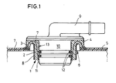
Wie dies aus Fig. 1 ersichtlich ist, ist der Einsatz 1 gemäß
der Erfindung als hohlzylindrisches, ringförmiges Element mit
einem zylindrischen Abschnitt 2 und einem einen Auflageflansch
3 bildenden Kragen 4 ausgebildet.As can be seen from FIG. 1, the
Mit 5 ist die Wandung eines im Co-Extrusions-Blasverfahren
hergestellten Kraftstofftanks bezeichnet, mit welcher der
Kragen 4 des Einsatzes 1 im peripheren Bereich einer Anschlußöffnung
6 verschweißt ist. Die Wandung 5 des Kraftstofftanks
besteht aus einem für Kohlenwasserstoffe schwer permeablen
Laminat mit einer Barriereschicht 7 aus EVOH (Ethylen-Vinyl-Alkohol).
Die Barriereschicht 7 bewirkt eine Absperrung gegen
das Hindurchtreten von Kohlenwasserstoffen durch die Wandung
5 des Tanks.At 5 the wall is one in the co-extrusion blow molding process
Manufactured fuel tanks with which the
Der in den Fig. 1 und 2 dargestellte Einsatz 1 besteht gemäß
der Erfindung ebenfalls aus einem für Kohlenwasserstoffe
schwer permeablen Laminat mit einer Barriereschicht 7. Die in
den Fig. 1 und 2 dargestellten Ausführungsbeispiele unterscheiden
sich insoweit, als daß der Verlauf der
Barriereschicht 7 dort jeweils unterschiedlich gewählt ist.
Bei dem in Fig. 1 gezeigten Ausführungsbeispiel verläuft die
Barriereschicht 7 im Bereich des zylindrischen Abschnitts 2
des Einsatzes 1 in einem Winkel zur Längsachse des Einsatzes
1 und befindet sich am unteren Ende des zylindrischen
Abschnitts 2 in der Nähe dessen Innenwandung 13. Im Bereich
des Kragens 4 tritt die Barriereschicht geringfügig oberhalb
des Auflageflanschs 3 aus.The
Bei der in Fig. 2 dargestellten zweiten Ausführungsform der
Erfindung verläuft die Barriereschicht 7 idealerweise zunächst
möglichst nahe an und parallel zu der Innenwandung 13 des
Einsatzes 1. Im Bereich des Kragens 4 verläuft die Barriereschicht
7 möglichst nahe an der Außenseite des Einsatzes 1 und
endet ziemlich genau in dem äußeren Eckbereich des Auflageflansches
3.In the second embodiment shown in FIG
According to the invention, the
Bei dem in Fig. 3 dargestellten dritten Ausführungsbeispiel
des Einsatzes 1 gemäß der Erfindung sind insgesamt zwei Barriereschichten
7 vorgesehen. Der genaue Schichtaufbau des
Einsatzes 1 gemäß dem in Fig. 3 dargestellten Ausführungsbeispiel
ergibt sich aus Fig. 7.In the third embodiment shown in FIG. 3
of
Da der Grundwerkstoff des Einsatzes 1 als auch des Tanks Polyethylen
ist, welches in Anwesenheit von Kohlenwasserstoffen
quillt, ist der Einsatz 1 mit einem metallenen Stützring 8
versehen, der eine Formänderung im Sinne einer Durchmesservergrößerung
des Einsatzes 1 aufgrund der Aufnahme von Kohlenwasserstoffen
verhindert und der den Einsatz 1 wie eine Manschette
umgibt. Sollte der Einsatz 1 aufgrund der Anwesenheit
von Kohlenwasserstoffen quellen, so kann dieser wegen des
Vorhandenseins des metallenen Stützrings 8 nur nach innen
ausweichen, so daß die Verbindung mit der Wandung 5 des Tanks
nicht beeinträchtigt wird. Darüber hinaus erfährt das im Einsatz
befindliche Teil, z. B. ein Ventil oder auch ein anderes
Teil, bezüglich seines Sitzes im Einsatz und der damit verbundenen
Abdichtung keine nachteiligen Einwirkungen.Since the base material of the
In dem in Fig. 1 dargestellten Ausführungsbeispiel dient der
Einsatz 1 als Dichtsitz für ein Ventil 9 aus POM (Polyoximethylen).
Das Ventil 9 besitzt einen zylindrischen Grundkörper
10, dessen Außenkontur und dessen Außendurchmesser etwa
der Innenkontur und dem Innendurchmesser des Einsatzes entspricht,
und zwar mit verhältnismäßig hoher Maßhaltigkeit.
Über Rastnasen 11 ist der Grundkörper 10 des Ventils 9 unlösbar
mit dem Einsatz 1 verrastet. Das Ventil 9 ist gegen den
Einsatz 1 mittels zweier O-Ring-Dichtungen 12 abgedichtet,
wobei eine der O-Ring-Dichtungen für den Tieftemperaturbereich
und die andere für den Hochtemperaturbereich vorgesehen ist.In the embodiment shown in FIG. 1, the
Wie dies insbesondere aus Fig. 2 ersichtlich ist, liegt die
Barriereschicht 7 im Bereich des Auflageflansches 3 möglichst
weit außen, um bei Verschweißen des Auflageflansches 3 mit der
Wandung 5 des Tanks einen Anschluß der Barriereschicht 7 des
Einsatzes 1 an die Barriereschicht 7 der Wandung 5 zu gewährleisten.
In jedem Fall sollte die Barriereschicht 7 in das
Grundmaterial des Einsatzes 1 eingebettet sein, um vor physikalischen
Verletzungen geschützt zu sein.As can be seen in particular from FIG. 2, the
Der in Fig. 4 dargestellte Einsatz 1 nimmt anstelle eines
Ventils einen Winkelstutzen aus POM (Polyoximethylen) auf. Bei
allen dargestellten Ausführungsbeispielen ist eine verhältnismäßig
einfache Variante des Einsatzes 1 wiedergegeben, der
eine glatte Innenwandung 13 aufweist, wobei entweder der Winkelstutzen
14 oder das Ventil 9 unlösbar mit dem Einsatz 1
verrastet sind. Es ist ebenso denkbar, den Einsatz 1 mit einer
profilierten Innenwandung auszustatten, beispielsweise in Form
eines Gewindes, so daß das betreffende Anschlußelement mit dem
Einsatz 1 verschraubbar ist.The
In den Fig. 5 und 6 ist der Vorgang der Herstellung des Einsatzes
1 schematisch dargestellt. Mit 15 ist ein zweiteiliges
Werkzeug, bestehend aus Stempel 16 und Matritze 17 bezeichnet,
welches die Preßform zur Herstellung des Einsatzes bildet.
Gemäß dem bevorzugten Verfahren ist vorgesehen, daß der Einsatz
1 durch Extrudieren eines mehrschichtigen Schlauches 18
im Co-Extrusions-Verfahren erzeugt wird, wobei der Schlauch 18
in das geöffnete Werkzeug 15 (siehe Fig. 5) eingeführt wird. 5 and 6 is the process of making the
Die Teile des Werkzeugs 15, d. h. der Stempel 16 und die Matritze
17 werden aufeinanderzubewegt, wobei der Schlauch 18
die Kavität 19 des Werkzeugs 15 ausfüllt. Durch die auf die
Matritze 17 und den Stempel 16 aufgebrachten Schließkräfte
wird das überschüssige Material teilweise abgequetscht und
teilweise in den Ausgleichsraum 20 getrieben. Der vorzugsweise
aus sechs Schichten co-extrudierte Schlauch wird zu einem
insgesamt zwölfschichtigen Gebilde zusammengepreßt.The parts of the
Nach dem Entformen des Einsatzes 1 müssen das an diesem noch
befestigte Ausgleichsvolumen sowie die seitlichen Überstände
entfernt werden.After the
Der fertige Einsatz hat den in Fig. 7 schematisch dargestellten
Aufbau aus insgesamt zwölf parallelen Schichten, von denen
die beiden äußeren Schichten 21 beispielsweise aus Polyethylen
bestehen, an diese schließen sich jeweils Schichten aus Regenerat
22 an. Unter Regenerat 22 ist rückgeführtes Material zu
verstehen, was beispielsweise bei der Herstellung des Tanks
bzw. Behälters oder bei der Herstellung des Einsatzes 1 als
Abfallmaterial (scrap) angefallen ist.The finished insert has the one shown schematically in FIG. 7
Construction from a total of twelve parallel layers, of which
the two
Die aus EVOH (Ethylen-Vinyl-Alkohol) bestehenden Barriereschichten
7 sind jeweils in eine Haftvermittlerschicht 23
eingebettet, mit der eine Verbindung der Barriereschichten mit
dem Regenerat 22 oder den äußeren Schichten 21 aus Polyethylen
gewährleistet ist.The barrier layers made of EVOH (ethylene vinyl alcohol)
7 are each in an
Aufgrund der Herstellung des Einsatzes über einen co-extrudierten
Schlauch ergibt sich der insgesamt zwölfschichtige
Aufbau, bei dem alle Schichten wenigstens doppelt vorhanden
sind. Der zwölfschichtige Aufbau des Einsatzes 1 ist nur bei
dem in Fig. 3 dargestellten Ausführungsbeispiel verwirklicht,
bei welchem insgesamt zwei Barriereschichten 7 vorgesehen
sind.Due to the manufacture of the insert via a co-extruded one
Tube results in a total of twelve layers
Structure in which all layers exist at least twice
are. The twelve-layer structure of
Claims (9)
- An insert of thermoplastic material for connection to a hollow body of thermoplastic material, in particular in the form of a component for lining a connection opening of a fuel tank and/or a seat for a connection element, characterized in that the insert (1) was obtained by press shaping of a laminate involving a low level of permeability for hydrocarbons, that the insert comprises a laminate with at least one barrier layer (7) for hydrocarbons and that the barrier layers (7) comprise ethylene vinyl alcohol.
- An insert according to claim 1 characterised in that the insert (1) can be connected to the fuel tank by a connection involving joining of the materials concerned, preferably by welding.
- An insert according to one of claims 1 or 2 characterised in that the barrier layer or layers (7) is or are almost completely embedded into the material of the insert (1), preferably at least in the region of a cylindrical portion (3) of the insert (1) near the inside wall (13) thereof.
- An insert according to one of claims 1 to 3 characterised in that there are at least two barrier layers.
- An insert according to one of claims 1 to 4 characterised in that the barrier layers (7) are embedded in a main body substantially comprising polyethylene.
- A process for producing an insert for sealing and non-releasable connection to a fuel tank of thermoplastic material, characterised in that the insert is obtained by press shaping of softened thermoplastic material in the form of an extrudate or semifinished product in the form of a laminate with a low level of permeability for hydrocarbons in a multi-part mould.
- A process according to claim 6 characterised by co-extrusion of a multi-layer preform and pressing of the preform in the first heat to the definitive shape.
- A process according to one of claims 6 and 7 characterised in that the preform is extruded in the form of a tube whose oppositely disposed walls are pressed against each other in the pressing mould.
- A hollow body of thermoplastic material, in particular a fuel tank, including an insert according to one of claims 1 to 5.
Applications Claiming Priority (2)
| Application Number | Priority Date | Filing Date | Title |
|---|---|---|---|
| DE19943673A DE19943673A1 (en) | 1999-09-13 | 1999-09-13 | Tank insert and process for its manufacture |
| DE19943673 | 1999-09-13 |
Publications (2)
| Publication Number | Publication Date |
|---|---|
| EP1084889A1 EP1084889A1 (en) | 2001-03-21 |
| EP1084889B1 true EP1084889B1 (en) | 2004-06-09 |
Family
ID=7921750
Family Applications (1)
| Application Number | Title | Priority Date | Filing Date |
|---|---|---|---|
| EP00117409A Expired - Lifetime EP1084889B1 (en) | 1999-09-13 | 2000-08-11 | Tank insert and method for its manufacturing |
Country Status (7)
| Country | Link |
|---|---|
| US (1) | US20040124567A1 (en) |
| EP (1) | EP1084889B1 (en) |
| JP (1) | JP3528154B2 (en) |
| AT (1) | ATE268704T1 (en) |
| CA (1) | CA2318653A1 (en) |
| DE (2) | DE19943673A1 (en) |
| ES (1) | ES2220304T3 (en) |
Cited By (2)
| Publication number | Priority date | Publication date | Assignee | Title |
|---|---|---|---|---|
| US6915812B2 (en) | 2000-09-12 | 2005-07-12 | Alfmeier Corporation | Low permeation weldable fuel tank assembly |
| US6966330B2 (en) | 2003-08-27 | 2005-11-22 | Alfmeier Corporation | Weldring with locking arrangement for valve assembly |
Families Citing this family (26)
| Publication number | Priority date | Publication date | Assignee | Title |
|---|---|---|---|---|
| US6652699B1 (en) | 2000-02-17 | 2003-11-25 | Salflex Polymers Ltd. | Flanged member with barrier layer |
| US6860398B2 (en) * | 2000-11-30 | 2005-03-01 | Visteon Global Technologies, Inc. | Low permeation fittings, low permeation containers utilizing same, and methods for forming same |
| AT4938U1 (en) * | 2001-01-19 | 2002-01-25 | Tesma Motoren Getriebetechnik | FUEL TANK WITH LID |
| US6669043B2 (en) | 2001-09-27 | 2003-12-30 | Visteon Global Technologies, Inc. | Passthru device for internalized component fuel tanks |
| DE10328961A1 (en) * | 2003-06-27 | 2005-01-13 | Volkswagen Ag | Fuel supply installation, in particular, for a motor vehicle comprises a fuel tank with an opening provided with fixing ring incorporating means which form an axial catch for a flange with a fuel delivery module |
| JP2005090595A (en) * | 2003-09-16 | 2005-04-07 | Mitsubishi Plastics Ind Ltd | Electric fusion joint, and method for manufacturing the same |
| US7565986B2 (en) * | 2003-12-02 | 2009-07-28 | Ti Group Automotive Systems, L.L.C. | Fuel system component and method of manufacture |
| US7704440B2 (en) * | 2003-12-02 | 2010-04-27 | Ti Group Automotive Systems, L.L.C. | Fuel system component and method of manufacture |
| JP4442325B2 (en) * | 2004-05-31 | 2010-03-31 | 東洋製罐株式会社 | Method for producing multilayer structure |
| KR101280334B1 (en) * | 2004-11-30 | 2013-07-01 | 티아이 그룹 오토모티브 시스템즈 엘엘씨 | Fuel system component and method of manufacture |
| JP4991172B2 (en) * | 2006-03-27 | 2012-08-01 | 株式会社ニフコ | Fuel tank connector |
| JP5010294B2 (en) * | 2007-01-22 | 2012-08-29 | エクセル株式会社 | Sealing structure of through-holes formed in the wall of plastic hollow molding |
| JP2008201365A (en) * | 2007-02-22 | 2008-09-04 | Tokai Rubber Ind Ltd | Joint component for resin fuel tank and manufacturing method therefor |
| US20080314670A1 (en) * | 2007-06-20 | 2008-12-25 | Buell Motorcycle Company | Fuel pump mounting for a motorcycle |
| US20090127805A1 (en) * | 2007-11-20 | 2009-05-21 | Eaton Corporation | Assembly for Sealing a Component and Method |
| FR2929891B1 (en) * | 2008-04-10 | 2010-09-03 | Inergy Automotive Systems Res | METHOD FOR FASTENING A COMPONENT IN A FUEL TANK |
| DE102008036538A1 (en) * | 2008-08-06 | 2010-04-22 | Kautex Textron Gmbh & Co Kg | Motor vehicle fuel tank |
| CN101823425B (en) | 2009-01-22 | 2014-05-21 | 麦格纳斯太尔燃油系统公司 | Fuel tank having installations and method for the production thereof |
| DE102009005826A1 (en) | 2009-01-22 | 2010-07-29 | Magna Steyr Fuel Systems Gmbh | Fuel tank with built-in additional tank |
| JP5690092B2 (en) * | 2010-07-29 | 2015-03-25 | 本田技研工業株式会社 | Fuel tank seal structure and fuel tank manufacturing method |
| DE102010032931A1 (en) * | 2010-07-30 | 2012-02-02 | Kautex Textron Gmbh & Co. Kg | Container made of thermoplastic material |
| US9347545B2 (en) * | 2012-07-12 | 2016-05-24 | Gm Global Technology Operations, Llc | Transmission vent cap |
| DE102014207589B4 (en) * | 2014-04-22 | 2023-09-28 | Volkswagen Aktiengesellschaft | Method for producing a liquid container |
| EP3124305A1 (en) | 2015-07-31 | 2017-02-01 | Plastic Omnium Advanced Innovation and Research | A liquid vehicle tank comprising fastened component |
| EP3127735B1 (en) | 2015-08-07 | 2017-07-05 | Magna Steyr Fuel Systems GesmbH | Fuel filling neck for a vehicle with improved diffusion strength |
| CN111405999B (en) * | 2017-11-30 | 2023-03-17 | 本田技研工业株式会社 | Resin box |
Citations (1)
| Publication number | Priority date | Publication date | Assignee | Title |
|---|---|---|---|---|
| EP1063078A2 (en) * | 1999-06-21 | 2000-12-27 | Rasmussen GmbH | Process for making a branch stub |
Family Cites Families (11)
| Publication number | Priority date | Publication date | Assignee | Title |
|---|---|---|---|---|
| US4212488A (en) * | 1978-06-21 | 1980-07-15 | Cook Richard L | Fitting for flexible walled receptacle |
| US4214767A (en) * | 1978-08-21 | 1980-07-29 | Gilson Brothers Company | Fuel tank including air entrapment chambers |
| DE3736164A1 (en) * | 1987-09-04 | 1989-03-16 | Kautex Werke Gmbh | METHOD FOR PRODUCING LAMINATES IN THE COEXTRUSION METHOD AND LAMINATES PRODUCED BY THIS METHOD |
| DE4239909C1 (en) * | 1992-11-27 | 1994-05-05 | Rasmussen Gmbh | Tubular plastic connector for flexible lines - comprises fibre reinforced first part with low creep, injected onto unreinforced second part |
| US5589241A (en) * | 1992-12-14 | 1996-12-31 | Ford Motor Company | Fuel tank having an integrallly molded permeation barrier |
| US5404907A (en) * | 1993-02-18 | 1995-04-11 | G. T. Products, Inc. | Weldable vapor vent valve for fuel tanks |
| DE4310884A1 (en) * | 1993-04-02 | 1994-10-06 | Huels Chemische Werke Ag | Multi-layer plastic tube |
| US5443874A (en) * | 1993-05-24 | 1995-08-22 | Mitsubishi Petrochemical Co., Ltd. | Hollow multi-layer molding |
| JPH07205264A (en) * | 1994-01-11 | 1995-08-08 | Nippon Steel Chem Co Ltd | Multilayer blow molded form |
| US5855926A (en) * | 1996-10-25 | 1999-01-05 | The Japan Steel Works, Ltd. | Method for extrusion-molding laminated parison and apparatus for the same |
| JP3417282B2 (en) * | 1998-01-13 | 2003-06-16 | トヨタ自動車株式会社 | Hollow resin container |
-
1999
- 1999-09-13 DE DE19943673A patent/DE19943673A1/en not_active Ceased
-
2000
- 2000-08-11 ES ES00117409T patent/ES2220304T3/en not_active Expired - Lifetime
- 2000-08-11 EP EP00117409A patent/EP1084889B1/en not_active Expired - Lifetime
- 2000-08-11 AT AT00117409T patent/ATE268704T1/en not_active IP Right Cessation
- 2000-08-11 DE DE50006734T patent/DE50006734D1/en not_active Expired - Lifetime
- 2000-09-01 JP JP2000265064A patent/JP3528154B2/en not_active Expired - Fee Related
- 2000-09-12 CA CA002318653A patent/CA2318653A1/en not_active Abandoned
-
2003
- 2003-12-15 US US10/735,998 patent/US20040124567A1/en not_active Abandoned
Patent Citations (1)
| Publication number | Priority date | Publication date | Assignee | Title |
|---|---|---|---|---|
| EP1063078A2 (en) * | 1999-06-21 | 2000-12-27 | Rasmussen GmbH | Process for making a branch stub |
Cited By (4)
| Publication number | Priority date | Publication date | Assignee | Title |
|---|---|---|---|---|
| US6915812B2 (en) | 2000-09-12 | 2005-07-12 | Alfmeier Corporation | Low permeation weldable fuel tank assembly |
| US7159607B2 (en) | 2003-01-31 | 2007-01-09 | Alfmeier Corporation | Low permeation weldable fuel tank assembly |
| US7275556B2 (en) | 2003-01-31 | 2007-10-02 | Alfmeier Corporation | Low permeation weldable fuel tank assembly |
| US6966330B2 (en) | 2003-08-27 | 2005-11-22 | Alfmeier Corporation | Weldring with locking arrangement for valve assembly |
Also Published As
| Publication number | Publication date |
|---|---|
| DE19943673A1 (en) | 2001-03-29 |
| CA2318653A1 (en) | 2001-03-13 |
| ATE268704T1 (en) | 2004-06-15 |
| ES2220304T3 (en) | 2004-12-16 |
| JP2001113590A (en) | 2001-04-24 |
| EP1084889A1 (en) | 2001-03-21 |
| JP3528154B2 (en) | 2004-05-17 |
| DE50006734D1 (en) | 2004-07-15 |
| US20040124567A1 (en) | 2004-07-01 |
Similar Documents
| Publication | Publication Date | Title |
|---|---|---|
| EP1084889B1 (en) | Tank insert and method for its manufacturing | |
| DE69634313T2 (en) | Container made of laminated easily separable material | |
| EP0182094B1 (en) | Method for making a container with a sealable opening, and container obtained thereby | |
| EP1894702B1 (en) | Method for manufacturing a fuel container | |
| EP0036967B1 (en) | Coextrusion blowmolding method of producing hollow plastic bodies | |
| WO2002036380A1 (en) | Double-walled fuel tank made of synthetic material | |
| EP1332064A1 (en) | Fuel tank | |
| EP2285549A2 (en) | Method for producing a fuel tank for a motor vehicle and fuel tank for a motor vehicle | |
| CH653601A5 (en) | PREFORMING MADE OF THERMOPLASTIC PLASTIC. | |
| DE19617349C1 (en) | Injection moulding of multilayered tubing | |
| EP3490776B1 (en) | Method for producing a liquid container, liquid container for a motor vehicle and injection molding tool | |
| DE102007024677A1 (en) | A method for producing a container of thermoplastic by extrusion blow molding and connecting element for use in such a method | |
| DE2419530C3 (en) | Tube-shaped container made of a multilayered thermoplastic resin film | |
| EP1414706B1 (en) | Method of manufacturing a packaging container | |
| DE60107514T2 (en) | Process for producing a multilayer hollow body and blow molding tool with pinch edges | |
| DE3407060A1 (en) | METHOD FOR PRODUCING A PREFORM FOR BLOW MOLDING A HOLLOW BODY | |
| DE3439285A1 (en) | Blow-moulded tubes with projections - produced by feeding melt to recess in one mould cavity extruding tubular parison into cavity applying second mould tool and blowing | |
| EP0349872B1 (en) | Method and apparatus for the manufacture of hollow bodies from thermoplastics material | |
| DE1917889C3 (en) | Packaging container made of a thin-walled, inner hollow body made of plastic and a casing that at least partially surrounds it, as well as a method for its production | |
| EP1631469B1 (en) | Extrusion blow-molded filling tube made of plastic | |
| DE19911424A1 (en) | Pressed profile for vehicles useful e.g. as window, exterior, interior or roof-sealing profile | |
| EP0619174A1 (en) | Process for making thermoplastic hollow objects | |
| EP0894608A2 (en) | Method of manufacturing a hot water bottle and hot water bottle manufactured by this process | |
| DE102017128333B3 (en) | Adapter and method of manufacturing a container using the adapter and container with the adapter | |
| DE3516470A1 (en) | METHOD AND DEVICE FOR PRODUCING BLOW-MOLDED HOLLOW BODIES FROM THERMOPLASTIC PLASTICS |
Legal Events
| Date | Code | Title | Description |
|---|---|---|---|
| PUAI | Public reference made under article 153(3) epc to a published international application that has entered the european phase |
Free format text: ORIGINAL CODE: 0009012 |
|
| AK | Designated contracting states |
Kind code of ref document: A1 Designated state(s): AT BE CH CY DE DK ES FI FR GB GR IE IT LI LU MC NL PT SE |
|
| AX | Request for extension of the european patent |
Free format text: AL;LT;LV;MK;RO;SI |
|
| 17P | Request for examination filed |
Effective date: 20010526 |
|
| AKX | Designation fees paid |
Free format text: AT BE CH CY DE DK ES FI FR GB GR IE IT LI LU MC NL PT SE |
|
| 17Q | First examination report despatched |
Effective date: 20030722 |
|
| GRAP | Despatch of communication of intention to grant a patent |
Free format text: ORIGINAL CODE: EPIDOSNIGR1 |
|
| GRAS | Grant fee paid |
Free format text: ORIGINAL CODE: EPIDOSNIGR3 |
|
| GRAA | (expected) grant |
Free format text: ORIGINAL CODE: 0009210 |
|
| AK | Designated contracting states |
Kind code of ref document: B1 Designated state(s): AT BE CH CY DE DK ES FI FR GB GR IE IT LI LU MC NL PT SE |
|
| PG25 | Lapsed in a contracting state [announced via postgrant information from national office to epo] |
Ref country code: CY Free format text: LAPSE BECAUSE OF FAILURE TO SUBMIT A TRANSLATION OF THE DESCRIPTION OR TO PAY THE FEE WITHIN THE PRESCRIBED TIME-LIMIT Effective date: 20040609 Ref country code: NL Free format text: LAPSE BECAUSE OF FAILURE TO SUBMIT A TRANSLATION OF THE DESCRIPTION OR TO PAY THE FEE WITHIN THE PRESCRIBED TIME-LIMIT Effective date: 20040609 Ref country code: FI Free format text: LAPSE BECAUSE OF FAILURE TO SUBMIT A TRANSLATION OF THE DESCRIPTION OR TO PAY THE FEE WITHIN THE PRESCRIBED TIME-LIMIT Effective date: 20040609 Ref country code: IE Free format text: LAPSE BECAUSE OF FAILURE TO SUBMIT A TRANSLATION OF THE DESCRIPTION OR TO PAY THE FEE WITHIN THE PRESCRIBED TIME-LIMIT Effective date: 20040609 |
|
| REG | Reference to a national code |
Ref country code: GB Ref legal event code: FG4D Free format text: NOT ENGLISH |
|
| REG | Reference to a national code |
Ref country code: CH Ref legal event code: EP |
|
| REF | Corresponds to: |
Ref document number: 50006734 Country of ref document: DE Date of ref document: 20040715 Kind code of ref document: P |
|
| REG | Reference to a national code |
Ref country code: IE Ref legal event code: FG4D Free format text: GERMAN |
|
| PG25 | Lapsed in a contracting state [announced via postgrant information from national office to epo] |
Ref country code: AT Free format text: LAPSE BECAUSE OF NON-PAYMENT OF DUE FEES Effective date: 20040811 Ref country code: LU Free format text: LAPSE BECAUSE OF NON-PAYMENT OF DUE FEES Effective date: 20040811 |
|
| PG25 | Lapsed in a contracting state [announced via postgrant information from national office to epo] |
Ref country code: LI Free format text: LAPSE BECAUSE OF NON-PAYMENT OF DUE FEES Effective date: 20040831 Ref country code: CH Free format text: LAPSE BECAUSE OF NON-PAYMENT OF DUE FEES Effective date: 20040831 Ref country code: MC Free format text: LAPSE BECAUSE OF NON-PAYMENT OF DUE FEES Effective date: 20040831 |
|
| PG25 | Lapsed in a contracting state [announced via postgrant information from national office to epo] |
Ref country code: GR Free format text: LAPSE BECAUSE OF FAILURE TO SUBMIT A TRANSLATION OF THE DESCRIPTION OR TO PAY THE FEE WITHIN THE PRESCRIBED TIME-LIMIT Effective date: 20040909 Ref country code: DK Free format text: LAPSE BECAUSE OF FAILURE TO SUBMIT A TRANSLATION OF THE DESCRIPTION OR TO PAY THE FEE WITHIN THE PRESCRIBED TIME-LIMIT Effective date: 20040909 Ref country code: SE Free format text: LAPSE BECAUSE OF FAILURE TO SUBMIT A TRANSLATION OF THE DESCRIPTION OR TO PAY THE FEE WITHIN THE PRESCRIBED TIME-LIMIT Effective date: 20040909 |
|
| GBT | Gb: translation of ep patent filed (gb section 77(6)(a)/1977) |
Effective date: 20040825 |
|
| NLV1 | Nl: lapsed or annulled due to failure to fulfill the requirements of art. 29p and 29m of the patents act | ||
| REG | Reference to a national code |
Ref country code: ES Ref legal event code: FG2A Ref document number: 2220304 Country of ref document: ES Kind code of ref document: T3 |
|
| REG | Reference to a national code |
Ref country code: IE Ref legal event code: FD4D |
|
| ET | Fr: translation filed | ||
| PLBE | No opposition filed within time limit |
Free format text: ORIGINAL CODE: 0009261 |
|
| REG | Reference to a national code |
Ref country code: CH Ref legal event code: PL |
|
| STAA | Information on the status of an ep patent application or granted ep patent |
Free format text: STATUS: NO OPPOSITION FILED WITHIN TIME LIMIT |
|
| 26N | No opposition filed |
Effective date: 20050310 |
|
| PG25 | Lapsed in a contracting state [announced via postgrant information from national office to epo] |
Ref country code: PT Free format text: LAPSE BECAUSE OF NON-PAYMENT OF DUE FEES Effective date: 20041109 |
|
| PGFP | Annual fee paid to national office [announced via postgrant information from national office to epo] |
Ref country code: GB Payment date: 20080821 Year of fee payment: 9 |
|
| PGFP | Annual fee paid to national office [announced via postgrant information from national office to epo] |
Ref country code: ES Payment date: 20090821 Year of fee payment: 10 |
|
| PGFP | Annual fee paid to national office [announced via postgrant information from national office to epo] |
Ref country code: BE Payment date: 20090915 Year of fee payment: 10 |
|
| GBPC | Gb: european patent ceased through non-payment of renewal fee |
Effective date: 20090811 |
|
| PGFP | Annual fee paid to national office [announced via postgrant information from national office to epo] |
Ref country code: IT Payment date: 20090820 Year of fee payment: 10 |
|
| PG25 | Lapsed in a contracting state [announced via postgrant information from national office to epo] |
Ref country code: GB Free format text: LAPSE BECAUSE OF NON-PAYMENT OF DUE FEES Effective date: 20090811 |
|
| PGFP | Annual fee paid to national office [announced via postgrant information from national office to epo] |
Ref country code: DE Payment date: 20100730 Year of fee payment: 11 Ref country code: FR Payment date: 20100901 Year of fee payment: 11 |
|
| BERE | Be: lapsed |
Owner name: *KAUTEX TEXTRON G.M.B.H. & CO. K.G. Effective date: 20100831 |
|
| PG25 | Lapsed in a contracting state [announced via postgrant information from national office to epo] |
Ref country code: IT Free format text: LAPSE BECAUSE OF NON-PAYMENT OF DUE FEES Effective date: 20100811 |
|
| PG25 | Lapsed in a contracting state [announced via postgrant information from national office to epo] |
Ref country code: BE Free format text: LAPSE BECAUSE OF NON-PAYMENT OF DUE FEES Effective date: 20100831 |
|
| REG | Reference to a national code |
Ref country code: ES Ref legal event code: FD2A Effective date: 20111019 |
|
| PG25 | Lapsed in a contracting state [announced via postgrant information from national office to epo] |
Ref country code: ES Free format text: LAPSE BECAUSE OF NON-PAYMENT OF DUE FEES Effective date: 20100812 |
|
| REG | Reference to a national code |
Ref country code: FR Ref legal event code: ST Effective date: 20120430 |
|
| REG | Reference to a national code |
Ref country code: DE Ref legal event code: R119 Ref document number: 50006734 Country of ref document: DE Effective date: 20120301 |
|
| PG25 | Lapsed in a contracting state [announced via postgrant information from national office to epo] |
Ref country code: FR Free format text: LAPSE BECAUSE OF NON-PAYMENT OF DUE FEES Effective date: 20110831 |
|
| REG | Reference to a national code |
Ref country code: DE Ref legal event code: R082 Ref document number: 50006734 Country of ref document: DE Representative=s name: FLEISCHER, GODEMEYER, KIERDORF & PARTNER, PATE, DE |
|
| PG25 | Lapsed in a contracting state [announced via postgrant information from national office to epo] |
Ref country code: DE Free format text: LAPSE BECAUSE OF NON-PAYMENT OF DUE FEES Effective date: 20120301 |