EP1084881A1 - Open roof construction for a vehicle - Google Patents
Open roof construction for a vehicle Download PDFInfo
- Publication number
- EP1084881A1 EP1084881A1 EP00203135A EP00203135A EP1084881A1 EP 1084881 A1 EP1084881 A1 EP 1084881A1 EP 00203135 A EP00203135 A EP 00203135A EP 00203135 A EP00203135 A EP 00203135A EP 1084881 A1 EP1084881 A1 EP 1084881A1
- Authority
- EP
- European Patent Office
- Prior art keywords
- closure element
- guide rail
- roof construction
- operating mechanism
- roof
- Prior art date
- Legal status (The legal status is an assumption and is not a legal conclusion. Google has not performed a legal analysis and makes no representation as to the accuracy of the status listed.)
- Granted
Links
- 238000010276 construction Methods 0.000 title claims abstract description 26
- 230000007246 mechanism Effects 0.000 claims abstract description 30
- 230000007704 transition Effects 0.000 claims 1
- 239000002184 metal Substances 0.000 description 9
- 238000004519 manufacturing process Methods 0.000 description 4
- 230000009977 dual effect Effects 0.000 description 3
- 239000000463 material Substances 0.000 description 3
- 238000000465 moulding Methods 0.000 description 2
- 239000007787 solid Substances 0.000 description 2
- 238000005452 bending Methods 0.000 description 1
- 230000008878 coupling Effects 0.000 description 1
- 238000010168 coupling process Methods 0.000 description 1
- 238000005859 coupling reaction Methods 0.000 description 1
- 230000000694 effects Effects 0.000 description 1
- 238000001746 injection moulding Methods 0.000 description 1
- 238000000034 method Methods 0.000 description 1
- 238000010008 shearing Methods 0.000 description 1
Images


Classifications
-
- B—PERFORMING OPERATIONS; TRANSPORTING
- B60—VEHICLES IN GENERAL
- B60J—WINDOWS, WINDSCREENS, NON-FIXED ROOFS, DOORS, OR SIMILAR DEVICES FOR VEHICLES; REMOVABLE EXTERNAL PROTECTIVE COVERINGS SPECIALLY ADAPTED FOR VEHICLES
- B60J7/00—Non-fixed roofs; Roofs with movable panels, e.g. rotary sunroofs
- B60J7/02—Non-fixed roofs; Roofs with movable panels, e.g. rotary sunroofs of sliding type, e.g. comprising guide shoes
- B60J7/04—Non-fixed roofs; Roofs with movable panels, e.g. rotary sunroofs of sliding type, e.g. comprising guide shoes with rigid plate-like element or elements, e.g. open roofs with harmonica-type folding rigid panels
- B60J7/05—Non-fixed roofs; Roofs with movable panels, e.g. rotary sunroofs of sliding type, e.g. comprising guide shoes with rigid plate-like element or elements, e.g. open roofs with harmonica-type folding rigid panels pivoting upwardly to vent mode and moving downward before sliding to fully open mode
Definitions
- the invention relates to an open roof construction in accordance with the preamble of claim 1.
- the object of the invention is to further improve the open roof construction of the kind referred to in the introduction.
- said element consists of a cam
- said counter elements consist of camways
- said cam is preferably formed on the closure element and said camways are formed on the element in the form of a link slide.
- the invention is especially advantageous if the link slide is divided in longitudinal direction, being made of two interconnected halves.
- the camways may be shifted in horizontal direction with respect to each other due to the fact that the two parts of the link slide are not entirely correctly aligned. Since the camways will generally exhibit a fairly steep slope, the cams may easily jam if two cams are used, which will result in variations in the required driving force, an increased noise level of the driving mechanism and a loss of "sense of quality" in the driving mechanism. This is avoided with the open roof construction according to the invention.
- FIG. 1 - 4 show an exemplary embodiment of the open roof construction according to the invention, which is built into a vehicle, such as a passenger car, in whose fixed roof 1 a roof opening 2 is present.
- the open roof construction comprises a frame 3 or different stationary part, which can be attached to the fixed roof 1, or which is formed thereon.
- Said frame 3 supports, in a manner to be described in more detail hereafter, a closure element 4 which is capable of selectively closing the roof opening 2 or releasing it at least partially.
- the open roof construction is a so-called sliding-tilt roof, wherein the closure element 4 is in the form of a transparent, rigid panel, which can be moved from the closed position in roof opening 2 (Fig. 2), on the one hand to an upwardly sloping ventilating position (Fig. 1) and on the other hand downwards (Fig. 3) and subsequently rearwards to a position under the fixed roof 1 (Fig. 4).
- panel 4 is fitted with an operating mechanism at both longitudinal edges, one of which is shown in the drawings, whereby it should be considered, however, that the same operating mechanism is disposed at the other longitudinal edge of panel 4 in mirror image thereof.
- Said operating mechanisms are disposed in guide rails 5, which are mounted in frame 3 or integrated therein and which extend on either side of the roof opening 2 and rearwards thereof under fixed roof 1.
- Each operating mechanism is actuated by a driving slide 6, which is guided in the associated guide rail 5 and which can be moved along guide rail 5 by means of a pull-push cable (not shown) or other connecting element which is connected to a drive unit such as an electric motor, a crank handle or the like.
- a vertically adjustable member in the form of an arm 7 is attached to the driving slide, which arm is connected to the driving slide 6 by means of a horizontal, transversely extending pivot 8.
- the arm 7 of driving slide 6 includes a first guide member 9 in the form of a double guide cam, which is in engagement with a guideway 10 in the form of a rib projecting in transverse direction, which is formed on a link plate 11 which is mounted on the underside of panel 4 and which extends in the longitudinal direction thereof.
- link plate 11 is formed of two abutting metal plates 12 or the like, which are each other's mirror image and on each of which various parts of the operating mechanism are formed in mirror image of each other. This also applies to guideway 10, which is formed on either side of link plate 11 by moulding plastic material on laterally projecting flanges 13 of the metal plates 12 (see Fig. 7).
- the metal plates 12 of the link plate 11 widely diverge, forming legs 14, on the lower ends of which sliding shoes 15 are moulded, which sliding shoes are accommodated in associated grooves 16 of the guide rail and which are formed such that they are not only capable of sliding movement but also allow rotation about a transverse axis, so that the sliding shoes 15 serve as pivots at the same time.
- a correction mechanism 17 Disposed some distance behind the front sliding shoes 15 or the front pivot 15 of panel 4 is a correction mechanism 17, which causes panel 4 to move slightly rearwards upon pivoting from the closed position which is shown in Fig. 2 to the ventilating position which is shown in Fig. 1, so as to detach a seal 18 on the front side of panel 4 from the edge of the fixed roof 1, thus to prevent said seal 18 from being exposed to high shearing forces upon being moved downwards slightly due to the pivoting movement of panel 4.
- Said correction mechanism 17 comprises a cam 19 that is formed on either one of the two metal plates 12 of link plate 11, which cam is in engagement with either one of the camways 20 that are formed on a link slide 21, which will be explained in more detail yet.
- the link slide remains stationary during pivoting movement of panel 4 and moves along when the panel moves in the longitudinal direction of guide rail 5, so that cams 19 and camways 20 can remain in constant engagement with each other because cams 19 allow rearward movement of panel 4 in a lowermost position in camways 20.
- Said link slide 21 is made up of two interconnected metal plates 35 and 36 formed by cutting and bending, and it is substantially symmetrical relative to a vertical longitudinal plane through the link slide, so that the same link slide 21 can be used on the left-hand side and on the right-hand side of the roof opening.
- Link slide 21 cooperates with the driving slide 6 in various manners.
- Driving slide 6 and link slide 21 are guided in two separate, adjoining guideways 5' and 5'' of guide rail 5, but driving slide 6 is guided along an upright flange 32 between the two guideways 5' and 5'', and projects laterally into guideway 5''.
- Dual second guide members 22 and second guideways 23 are used again, wherein the guideways 23 are facing ribs between which the two twin cams of the second guide member 22 are positioned (see Fig. 7).
- the guideways 10 and 23 are substantially the same length, whilst they are furthermore disposed at least substantially above each other and exhibit approximately the same slope, albeit in opposite direction.
- the guideways 10 and 23 are so formed and positioned that they can at least partially overlap upon pivoting movement of link plate 11 under the influence of the movement of the first and the second guide member 9, 22 of arm 7 along guideway 10.
- the sliding block of the arm 7 in which the guide members 9 and 22 are formed is capable of transmitting forces being exerted on panel 4 directly to the link slide 21, as a result of which arm 7 is hardly loaded, if at all, and a very stable support of the panel can be ensured. This effect is further enhanced by the dual construction of guide members 9, 22 and guideways 10, 23.
- link plate 21 only moves so as to enable movement of panel 4 in longitudinal direction, it must remain stationary during the other movements of panel 4 in vertical direction, and consequently driving slide 6 must move relative to link slide 21 in that case.
- driving slide 6 and link slide 21 move as one unit.
- Cam 19 and camways 20 are formed by moulding plastic material round metal parts of link plate 11 and link slide 21.
- a horizontal lip 33 (see Fig. 6) is formed on either one of the two metal plates 12 of link plate 11, which lip functions to support the plastic cam 19, whilst two vertical lips are cut/bent from each plate of link slide 21 (see opening 34), around which the plastic material for forming camway 30 has been formed by means of an injection moulding technique.
- the angle that camways 20 include with the horizontal is large, as a consequence of which a horizontal movement of the metal plate portions 35 and 36 of link slide 21 relative to each other due to production tolerances will result in a misalignment of said camways 20, which have been formed prior to interconnecting the metal plate portions 35 and 36. Since only one cam 19 is used, this does not present any problems. On the other hand, since the two camways 20 are maintained, it is possible to use the same link slide 21 both on the left and on the right, so that the number of parts will not increase.
- the invention provides an open roof construction which on the one hand is remarkable for its simplicity and its small overall height and which on the other hand provides a stable support, whilst the compensation mechanism is of solid and stable construction and insensitive to production tolerances, whilst it does not add to the number of different parts.
- the invention is not restricted to the above-described embodiment as shown in the drawing, which can be varied in several ways without departing from the scope of the invention.
- the invention can also be used with other kinds of open roof constructions such as tilt roofs, spoiler roofs and other types of roofs comprising panels or different single or multiple closure elements.
- the vertically adjustable part of the driving slide could also be in engagement via one guide pin or similar guide member with the guideways in the form of guide slots of the closure element and the stationary part.
- the guide members and guideways as well as the cam and the camways of the correction mechanism could also be kinematically reversed.
- the cam and the camways may also be of different construction, for example being formed with a pin and a slot or with a link rib and cams engaging therearound.
Landscapes
- Engineering & Computer Science (AREA)
- Mechanical Engineering (AREA)
- Fittings On The Vehicle Exterior For Carrying Loads, And Devices For Holding Or Mounting Articles (AREA)
- Body Structure For Vehicles (AREA)
- Conveying And Assembling Of Building Elements In Situ (AREA)
Abstract
Description
- The invention relates to an open roof construction in accordance with the preamble of
claim 1. - In Dutch patent application No. 1011863 (=EP 00201260.7) (not pre-published), from which the present invention departs, the element and the counter element consist of two cams formed on the panel and two camways formed on a link slide, respectively. Although the twin construction provides a solid structure, it has the drawback that if the two cams or camways are not properly aligned, the cams may jam in the camways, which may interfere with the smooth operation of the operating mechanism.
- The object of the invention is to further improve the open roof construction of the kind referred to in the introduction.
- To this end the open roof construction according to the invention is characterised by the features defined in the characterizing portion of
claim 1. - By constructing either one of said element and said counter element as twin elements, parts such as the element of the operating mechanism can remain identical on the left and on the right, which simplifies production and stockkeeping. Jamming problems are avoided by using only one element or counter element for the correction mechanism, as a result of which the correction mechanism is less sensitive to production tolerances, whilst a smooth operation of the operating mechanism is nevertheless ensured.
- In an advantageous embodiment said element consists of a cam, and said counter elements consist of camways, wherein said cam is preferably formed on the closure element and said camways are formed on the element in the form of a link slide.
- The invention is especially advantageous if the link slide is divided in longitudinal direction, being made of two interconnected halves.
- In an embodiment of this kind the camways may be shifted in horizontal direction with respect to each other due to the fact that the two parts of the link slide are not entirely correctly aligned. Since the camways will generally exhibit a fairly steep slope, the cams may easily jam if two cams are used, which will result in variations in the required driving force, an increased noise level of the driving mechanism and a loss of "sense of quality" in the driving mechanism. This is avoided with the open roof construction according to the invention.
- The invention will now be explained in more detail with reference to the drawing, which shows an embodiment of the open roof construction according to the invention.
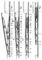
- Figs. 1 - 4 are longitudinal sectional views of the embodiment of the open roof construction according to the invention, showing four different positions thereof.
- Fig. 5 is a perspective view of the main components of the operating mechanism of the open roof construction of Figs. 1 - 4.
- Fig. 6 is a larger-scale cross-sectional view along the line VI-VI in Fig. 2.
- Fig. 7 is a larger-scale cross-sectional view along the line VII-VII in Fig. 2.
-
- The drawings, and in the first instance Figs. 1 - 4, show an exemplary embodiment of the open roof construction according to the invention, which is built into a vehicle, such as a passenger car, in whose fixed roof 1 a roof opening 2 is present. The open roof construction comprises a frame 3 or different stationary part, which can be attached to the
fixed roof 1, or which is formed thereon. Said frame 3 supports, in a manner to be described in more detail hereafter, aclosure element 4 which is capable of selectively closing the roof opening 2 or releasing it at least partially. - In the illustrated embodiment the open roof construction is a so-called sliding-tilt roof, wherein the
closure element 4 is in the form of a transparent, rigid panel, which can be moved from the closed position in roof opening 2 (Fig. 2), on the one hand to an upwardly sloping ventilating position (Fig. 1) and on the other hand downwards (Fig. 3) and subsequently rearwards to a position under the fixed roof 1 (Fig. 4). - In order to enable these movements,
panel 4 is fitted with an operating mechanism at both longitudinal edges, one of which is shown in the drawings, whereby it should be considered, however, that the same operating mechanism is disposed at the other longitudinal edge ofpanel 4 in mirror image thereof. Said operating mechanisms are disposed inguide rails 5, which are mounted in frame 3 or integrated therein and which extend on either side of the roof opening 2 and rearwards thereof underfixed roof 1. Each operating mechanism is actuated by adriving slide 6, which is guided in the associatedguide rail 5 and which can be moved alongguide rail 5 by means of a pull-push cable (not shown) or other connecting element which is connected to a drive unit such as an electric motor, a crank handle or the like. - As is also clearly shown in Fig. 5, a vertically adjustable member in the form of an
arm 7 is attached to the driving slide, which arm is connected to thedriving slide 6 by means of a horizontal, transversely extendingpivot 8. Thearm 7 of drivingslide 6 includes afirst guide member 9 in the form of a double guide cam, which is in engagement with aguideway 10 in the form of a rib projecting in transverse direction, which is formed on alink plate 11 which is mounted on the underside ofpanel 4 and which extends in the longitudinal direction thereof. - As is shown in Figs. 5 and 7,
link plate 11 is formed of twoabutting metal plates 12 or the like, which are each other's mirror image and on each of which various parts of the operating mechanism are formed in mirror image of each other. This also applies toguideway 10, which is formed on either side oflink plate 11 by moulding plastic material on laterally projectingflanges 13 of the metal plates 12 (see Fig. 7). - On the front side, the
metal plates 12 of thelink plate 11 widely diverge, forminglegs 14, on the lower ends of which slidingshoes 15 are moulded, which sliding shoes are accommodated in associatedgrooves 16 of the guide rail and which are formed such that they are not only capable of sliding movement but also allow rotation about a transverse axis, so that thesliding shoes 15 serve as pivots at the same time. This leads to a reduction of the number of parts. - Disposed some distance behind the
front sliding shoes 15 or thefront pivot 15 ofpanel 4 is acorrection mechanism 17, which causespanel 4 to move slightly rearwards upon pivoting from the closed position which is shown in Fig. 2 to the ventilating position which is shown in Fig. 1, so as to detach aseal 18 on the front side ofpanel 4 from the edge of thefixed roof 1, thus to prevent saidseal 18 from being exposed to high shearing forces upon being moved downwards slightly due to the pivoting movement ofpanel 4. Saidcorrection mechanism 17 comprises acam 19 that is formed on either one of the twometal plates 12 oflink plate 11, which cam is in engagement with either one of thecamways 20 that are formed on alink slide 21, which will be explained in more detail yet. The link slide remains stationary during pivoting movement ofpanel 4 and moves along when the panel moves in the longitudinal direction ofguide rail 5, so thatcams 19 andcamways 20 can remain in constant engagement with each other becausecams 19 allow rearward movement ofpanel 4 in a lowermost position incamways 20. - Said
link slide 21 is made up of twointerconnected metal plates same link slide 21 can be used on the left-hand side and on the right-hand side of the roof opening.Link slide 21 cooperates with thedriving slide 6 in various manners. Drivingslide 6 andlink slide 21 are guided in two separate, adjoining guideways 5' and 5'' ofguide rail 5, but drivingslide 6 is guided along anupright flange 32 between the two guideways 5' and 5'', and projects laterally into guideway 5''. Besidesfirst guide member 9,arm 7 of drivingslide 6, which extends above guideway 5'', also has a second,guide member 22, likewise in the form of dual cams engaging round asecond guideway 23 onlink slide 21. Dualsecond guide members 22 andsecond guideways 23 are used again, wherein theguideways 23 are facing ribs between which the two twin cams of thesecond guide member 22 are positioned (see Fig. 7). Theguideways guideways link plate 11 under the influence of the movement of the first and thesecond guide member arm 7 alongguideway 10. The sliding block of thearm 7 in which theguide members panel 4 directly to thelink slide 21, as a result of whicharm 7 is hardly loaded, if at all, and a very stable support of the panel can be ensured. This effect is further enhanced by the dual construction ofguide members guideways - As already mentioned before,
link plate 21 only moves so as to enable movement ofpanel 4 in longitudinal direction, it must remain stationary during the other movements ofpanel 4 in vertical direction, and consequently drivingslide 6 must move relative tolink slide 21 in that case. Whenpanel 4 moves in longitudinal direction, drivingslide 6 andlink slide 21 move as one unit. - Special locking, coupling and operating means 24 - 31, which will not be further explained herein, are provided for locking
link slide 21 in position and releasing it. For an explanation the reader is referred to Dutch patent application No. 1011863 (EP 002012670.7), the contents of which are incorporated herein by reference thereto. -
Cam 19 andcamways 20 are formed by moulding plastic material round metal parts oflink plate 11 andlink slide 21. A horizontal lip 33 (see Fig. 6) is formed on either one of the twometal plates 12 oflink plate 11, which lip functions to support theplastic cam 19, whilst two vertical lips are cut/bent from each plate of link slide 21 (see opening 34), around which the plastic material for formingcamway 30 has been formed by means of an injection moulding technique. The angle thatcamways 20 include with the horizontal is large, as a consequence of which a horizontal movement of themetal plate portions link slide 21 relative to each other due to production tolerances will result in a misalignment of saidcamways 20, which have been formed prior to interconnecting themetal plate portions cam 19 is used, this does not present any problems. On the other hand, since the twocamways 20 are maintained, it is possible to use thesame link slide 21 both on the left and on the right, so that the number of parts will not increase. - The operation of the illustrated embodiment of the open roof construction according to the invention is in principle similar to that of the embodiments described in Dutch patent applications Nos. 1009773 (WO-A-00/06403), 1011863 (EP 00201260.7), 1012645 (EP 00202266.3) and 1012646 (EP 00202268.9) so that the reader is referred to said prior patent applications for a further explanation thereof, and the contents of said patent applications are incorporated herein by reference thereto.
- From the foregoing it will be understood that the invention provides an open roof construction which on the one hand is remarkable for its simplicity and its small overall height and which on the other hand provides a stable support, whilst the compensation mechanism is of solid and stable construction and insensitive to production tolerances, whilst it does not add to the number of different parts.
- The invention is not restricted to the above-described embodiment as shown in the drawing, which can be varied in several ways without departing from the scope of the invention. Thus the invention can also be used with other kinds of open roof constructions such as tilt roofs, spoiler roofs and other types of roofs comprising panels or different single or multiple closure elements. The vertically adjustable part of the driving slide could also be in engagement via one guide pin or similar guide member with the guideways in the form of guide slots of the closure element and the stationary part. The guide members and guideways as well as the cam and the camways of the correction mechanism could also be kinematically reversed. The cam and the camways may also be of different construction, for example being formed with a pin and a slot or with a link rib and cams engaging therearound.
- The invention is not restricted to the above-described embodiment as shown in the drawing, which can be varied in several ways without departing from the scope of the invention.
Claims (7)
- An open roof construction for a vehicle having an opening (2) in its fixed roof (1), comprising a stationary part (3) to be fixed to the roof, an adjustable closure element (4) supported by said stationary part, which is adjustable between a closed position, in which it closes the roof opening, and an open position, in which it releases the roof opening on the front side, wherein said stationary part comprises at least one guide rail (5) extending in the longitudinal direction of the vehicle, whilst the closure element includes a pivot member (15) near the front side and is slidably supported by at least one sliding shoe (15) which is capable of movement in said guide rail, whilst an operating mechanism for the closure element (4) is provided, which is arranged for effecting the pivoting movement of the closure element and movement of the closure element in the longitudinal direction of the guide rail (5), said operating mechanism including an element (21) which is at least substantially stationary during the pivoting movement of the closure element (4) and which moves along with the movement of the closure element, as well as a correction mechanism (17) disposed some distance behind said pivot member, which functions to move the closure element slightly in the longitudinal direction of the guide rail (5) upon pivoting movement of said closure element about the pivot member (15), which correction mechanism includes an assembly consisting of an element (19) and a counter element (20), wherein either one of said element (19) and said counter element (20) is connected to said closure element (4) and the other is formed on said element (21) of the operating mechanism, characterised in that parts of the operating mechanism on the element (21) and the closure element are twin parts, being substantially symmetrical with respect to a longitudinal plane, whilst only one of said element and said counter element is in the form of twin elements, the other being a single element.
- An open roof construction according to claim 1, wherein said element and said counter elements each consist of a cam (19) and a camway (20), respectively.
- An open roof construction according to claim 1 or 2, wherein said cam (19) is formed on said closure element (4) and said camways (20) are formed on the element (21) in the form of a link slide.
- An open roof construction according to claim 3, wherein said link slide (21) is divided in longitudinal direction, being made of two interconnected halves.
- An open roof construction according to any one of the preceding claims, wherein said closure element (4) is the panel of a sliding-tilt roof, which can on the one hand be pivoted from the closed position to a ventilating position and which can on the other hand be moved downwards and rearwards to a position under the fixed roof.
- An open roof construction according to claim 5, wherein said operating mechanism comprises a driving slide (6), which is engagement via a vertically adjustable element (7) with a guideway (23) on said panel (4) and with a guideway on a link slide (21) that is guided in said guide rail (5), which link slide includes a locking member (25), which locks the link slide (21) in position with respect to the guide rail during pivoting movements of the panel (4) and which can be released by the driving glide (6) at the transition to longitudinal movements of the panel (4), and wherein the camway (20) of the correction mechanism (17) is formed on said link slide (21).
- An open roof construction according to any one of the preceding claims, wherein the camways (20) of the assembly are positioned in opposite sense in transverse direction on either side of a link plate (11) on the closure element (4).
Applications Claiming Priority (2)
| Application Number | Priority Date | Filing Date | Title |
|---|---|---|---|
| NL1013053A NL1013053C2 (en) | 1999-09-15 | 1999-09-15 | Open roof construction for a vehicle. |
| NL1013053 | 1999-09-15 |
Publications (2)
| Publication Number | Publication Date |
|---|---|
| EP1084881A1 true EP1084881A1 (en) | 2001-03-21 |
| EP1084881B1 EP1084881B1 (en) | 2004-12-29 |
Family
ID=19769880
Family Applications (1)
| Application Number | Title | Priority Date | Filing Date |
|---|---|---|---|
| EP00203135A Expired - Lifetime EP1084881B1 (en) | 1999-09-15 | 2000-09-11 | Open roof construction for a vehicle |
Country Status (4)
| Country | Link |
|---|---|
| US (1) | US6419310B1 (en) |
| EP (1) | EP1084881B1 (en) |
| DE (1) | DE60017035T2 (en) |
| NL (1) | NL1013053C2 (en) |
Cited By (1)
| Publication number | Priority date | Publication date | Assignee | Title |
|---|---|---|---|---|
| CN104442315A (en) * | 2013-09-19 | 2015-03-25 | 韦巴斯托股份公司 | Vehicle sunroof device |
Families Citing this family (13)
| Publication number | Priority date | Publication date | Assignee | Title |
|---|---|---|---|---|
| EP1494883B1 (en) * | 2002-04-12 | 2007-08-08 | Inalfa Roof Systems Group B.V. | Roof assembly for a vehicle |
| DE60213202T2 (en) * | 2002-05-03 | 2007-07-19 | Inalfa Roof Systems Group B.V. | Openable roof construction for a vehicle and method for operating an associated closing element |
| US6695398B2 (en) * | 2002-06-13 | 2004-02-24 | Webasto Sunroofs, Inc. | Spoiler sunroof mechanism |
| DE102005045740B4 (en) * | 2005-09-23 | 2007-12-13 | Magna Car Top Systems Gmbh | Locking between a receiving part and a lid part |
| CN101977787B (en) * | 2009-02-09 | 2014-03-05 | 韦巴斯托股份公司 | Mechanism for adjustable body component of vehicle |
| EP2305500B1 (en) * | 2009-10-05 | 2013-09-25 | Inalfa Roof Systems Group B.V. | Open roof construction for a vehicle |
| EP2455247B1 (en) * | 2010-11-19 | 2013-04-10 | Roof Systems Germany GmbH | Sliding roof systems |
| JP6001303B2 (en) * | 2012-04-10 | 2016-10-05 | ベバスト ジャパン株式会社 | Sunroof device |
| JP6001304B2 (en) * | 2012-04-10 | 2016-10-05 | ベバスト ジャパン株式会社 | Sunroof device |
| JP6330558B2 (en) * | 2014-07-31 | 2018-05-30 | アイシン精機株式会社 | Sunroof device |
| JP6627423B2 (en) * | 2015-10-29 | 2020-01-08 | アイシン精機株式会社 | Moving equipment |
| EP3647094B1 (en) | 2018-11-05 | 2022-10-26 | Inalfa Roof Systems Group B.V. | Roof system for a vehicle |
| EP3792091B1 (en) | 2019-09-10 | 2022-06-15 | Inalfa Roof Systems Group B.V. | Roof assembly for a vehicle and a method of assembling |
Citations (8)
| Publication number | Priority date | Publication date | Assignee | Title |
|---|---|---|---|---|
| FR2495068A1 (en) * | 1980-11-28 | 1982-06-04 | Vermeulen Hollandia Octrooien | OPENING ROOF FOR VEHICLE |
| FR2527995A1 (en) * | 1982-06-07 | 1983-12-09 | Rockwell Golde Gmbh | CABLE GUIDE FOR SLIDING ROOFS OF VEHICLES |
| NL1009773C2 (en) | 1998-07-30 | 2000-02-01 | Inalfa Ind Bv | Slide and tilt mechanism for vehicle sun roof includes fixed frame and guide rails with motor=driven slide operating tilting and retracting mechanism |
| WO2000006403A2 (en) | 1998-07-30 | 2000-02-10 | Inalfa Industries B.V. | Open roof construction for a vehicle |
| NL1011863C2 (en) | 1999-04-22 | 2000-10-24 | Inalfa Ind Bv | Open roof construction for a vehicle. |
| NL1012646C2 (en) | 1999-07-20 | 2001-01-23 | Inalfa Ind Bv | Open roof construction for a vehicle. |
| NL1012645C2 (en) | 1999-07-20 | 2001-01-23 | Inalfa Ind Bv | Open roof construction for a vehicle. |
| EP1281551A2 (en) | 2001-07-30 | 2003-02-05 | DaimlerChrysler AG | Motor vehicle with open rigid roof |
Family Cites Families (28)
| Publication number | Priority date | Publication date | Assignee | Title |
|---|---|---|---|---|
| FR2474971A1 (en) | 1980-01-31 | 1981-08-07 | Renault | DEVICE FOR MANEUVERING A SUNROOF OF A MOTOR VEHICLE |
| DE3020675C2 (en) | 1980-05-30 | 1987-01-02 | Rockwell Golde Gmbh, 6000 Frankfurt | Lift and slide roof for motor vehicles |
| JPS6071327A (en) | 1983-09-29 | 1985-04-23 | Johnan Seisakusho Co Ltd | Opening and closing method for car sun roof and device thereof |
| EP0143589B1 (en) | 1983-11-25 | 1989-01-18 | Britax Weathershields Limited | Opening roof for a motor vehicle |
| DE3417098A1 (en) | 1984-05-09 | 1985-11-14 | Webasto-Werk W. Baier GmbH & Co, 8035 Gauting | VEHICLE SUNROOF |
| DE3444522A1 (en) | 1984-10-02 | 1986-04-10 | Webasto-Werk W. Baier GmbH & Co, 8035 Gauting | SLIDING LIFTING ROOF |
| DE3442600A1 (en) | 1984-11-22 | 1986-05-28 | Daimler-Benz Ag, 7000 Stuttgart | Sliding and tilt-up roof |
| JPS61278422A (en) | 1985-06-04 | 1986-12-09 | Oi Seisakusho Co Ltd | Sunroofing device for vehicle |
| DE3529118C1 (en) | 1985-08-14 | 1990-01-25 | Adam Opel Ag, 6090 Ruesselsheim, De | |
| DE3532679C1 (en) | 1985-09-13 | 1986-11-27 | Adam Opel AG, 6090 Rüsselsheim | Guide bolts in a sunroof arrangement |
| DE3537964C1 (en) | 1985-10-25 | 1987-02-19 | Rockwell Golde Gmbh | Cable guide for motor vehicle sliding roofs |
| DE3603314A1 (en) | 1986-02-04 | 1987-08-06 | Weinsberg Karosseriewerke | Tilt-and-slide sunroof for vehicles |
| NL8701492A (en) | 1987-06-25 | 1989-01-16 | Vermeulen Hollandia Octrooien | OPEN ROOF CONSTRUCTION FOR A VEHICLE. |
| DE3910894C3 (en) | 1988-04-05 | 2000-12-14 | Aisin Seiki | Movement mechanism for a lid of a vehicle roof cutout |
| NL8801359A (en) | 1988-05-27 | 1988-08-01 | Vermeulen Hollandia Octrooien | OPEN ROOF CONSTRUCTION FOR A VEHICLE. |
| NL8803010A (en) | 1988-12-08 | 1990-07-02 | Vermeulen Hollandia Octrooien | SLIDING ROOF FOR A VEHICLE. |
| DE3908645C1 (en) * | 1989-03-16 | 1990-06-13 | Rockwell Golde Gmbh, 6000 Frankfurt, De | |
| DE3930756A1 (en) | 1989-09-14 | 1991-03-28 | Webasto Ag Fahrzeugtechnik | Sliding and tilting sunroof operating mechanism - has two levers, fixed at one end to each other and extending in same direction |
| JPH04297323A (en) | 1991-01-29 | 1992-10-21 | Mazda Motor Corp | Openable roof structure for vehicle |
| NL9100972A (en) | 1991-06-06 | 1993-01-04 | Vermeulen Hollandia Octrooien | LIFT-SLIDING ROOF FOR A VEHICLE. |
| DE9116412U1 (en) | 1991-10-30 | 1992-12-24 | Locher, Gebhard, Sarnthein, Südtirol | Door handle arrangement |
| JP3269189B2 (en) | 1993-07-13 | 2002-03-25 | アイシン精機株式会社 | Sunroof device for vehicles |
| DE4405742C1 (en) | 1994-02-23 | 1995-05-04 | Wahl Peter Gmbh & Co | Slotted guide link for sliding panels on tilt-and-slide roof constructions for motor vehicles |
| DE19514585C5 (en) | 1995-04-20 | 2004-11-18 | Gubesch Gmbh | Sliding element for a link part of a sliding / lifting roof of a motor vehicle |
| DE19521278C1 (en) | 1995-06-10 | 1996-08-14 | Webasto Karosseriesysteme | Guide slideway for cover of sliding and lifting roof |
| JP3505307B2 (en) | 1996-01-08 | 2004-03-08 | ベバスト ジャパン株式会社 | Slide tilt roof device |
| NL1006867C2 (en) | 1997-08-28 | 1999-03-02 | Inalfa Ind Bv | Open roof construction for a vehicle. |
| US6164128A (en) | 1999-10-13 | 2000-12-26 | Santa Cruz; Cathy D. | Apparatus, method and formula relating to total-wind statistics |
-
1999
- 1999-09-15 NL NL1013053A patent/NL1013053C2/en not_active IP Right Cessation
-
2000
- 2000-09-11 EP EP00203135A patent/EP1084881B1/en not_active Expired - Lifetime
- 2000-09-11 DE DE60017035T patent/DE60017035T2/en not_active Expired - Lifetime
- 2000-09-13 US US09/661,231 patent/US6419310B1/en not_active Expired - Lifetime
Patent Citations (10)
| Publication number | Priority date | Publication date | Assignee | Title |
|---|---|---|---|---|
| FR2495068A1 (en) * | 1980-11-28 | 1982-06-04 | Vermeulen Hollandia Octrooien | OPENING ROOF FOR VEHICLE |
| FR2527995A1 (en) * | 1982-06-07 | 1983-12-09 | Rockwell Golde Gmbh | CABLE GUIDE FOR SLIDING ROOFS OF VEHICLES |
| NL1009773C2 (en) | 1998-07-30 | 2000-02-01 | Inalfa Ind Bv | Slide and tilt mechanism for vehicle sun roof includes fixed frame and guide rails with motor=driven slide operating tilting and retracting mechanism |
| WO2000006403A2 (en) | 1998-07-30 | 2000-02-10 | Inalfa Industries B.V. | Open roof construction for a vehicle |
| NL1011863C2 (en) | 1999-04-22 | 2000-10-24 | Inalfa Ind Bv | Open roof construction for a vehicle. |
| NL1012646C2 (en) | 1999-07-20 | 2001-01-23 | Inalfa Ind Bv | Open roof construction for a vehicle. |
| NL1012645C2 (en) | 1999-07-20 | 2001-01-23 | Inalfa Ind Bv | Open roof construction for a vehicle. |
| EP1070614A1 (en) | 1999-07-20 | 2001-01-24 | Inalfa Industries B.V. | Open roof construction for a vehicle |
| EP1070616A1 (en) | 1999-07-20 | 2001-01-24 | Inalfa Industries B.V. | Open roof construction for a vehicle |
| EP1281551A2 (en) | 2001-07-30 | 2003-02-05 | DaimlerChrysler AG | Motor vehicle with open rigid roof |
Cited By (3)
| Publication number | Priority date | Publication date | Assignee | Title |
|---|---|---|---|---|
| CN104442315A (en) * | 2013-09-19 | 2015-03-25 | 韦巴斯托股份公司 | Vehicle sunroof device |
| WO2015040018A1 (en) * | 2013-09-19 | 2015-03-26 | Webasto SE | Vehicle sunroof device |
| US9592723B2 (en) | 2013-09-19 | 2017-03-14 | Webasto SE | Vehicle sunroof device |
Also Published As
| Publication number | Publication date |
|---|---|
| DE60017035D1 (en) | 2005-02-03 |
| US6419310B1 (en) | 2002-07-16 |
| DE60017035T2 (en) | 2005-12-22 |
| NL1013053C2 (en) | 2001-03-16 |
| EP1084881B1 (en) | 2004-12-29 |
Similar Documents
| Publication | Publication Date | Title |
|---|---|---|
| EP1084881B1 (en) | Open roof construction for a vehicle | |
| EP1070614B1 (en) | Open roof construction for a vehicle | |
| EP1046529B1 (en) | Open roof construction for a vehicle | |
| EP1424234B1 (en) | An open roof construction for a vehicle | |
| US20090072588A1 (en) | Vehicle sun roof system | |
| KR900014169A (en) | Sliding Lifting Loop for Automotive | |
| EP1070616B1 (en) | Open roof construction for a vehicle | |
| EP1095807B1 (en) | An open roof construction for a vehicle | |
| US4647105A (en) | Opening roof for a motor vehicle | |
| EP0187398A1 (en) | Sliding roof for a vehicle | |
| EP0143589A2 (en) | Opening roof for a motor vehicle | |
| EP2305500B1 (en) | Open roof construction for a vehicle | |
| EP1359037A1 (en) | An open roof construction for a vehicle, and method of moving a closure element thereof | |
| EP0955194B1 (en) | Open roof construction for a vehicle | |
| EP1494883B1 (en) | Roof assembly for a vehicle | |
| JP4101360B2 (en) | Open roof structure for vehicles | |
| EP1070615B1 (en) | Open roof construction for a vehicle | |
| EP1046530A1 (en) | Open roof construction for a vehicle | |
| EP0348073B1 (en) | Opening roof for a motor vehicle | |
| GB2209795A (en) | Opening roof for motor vehicle |
Legal Events
| Date | Code | Title | Description |
|---|---|---|---|
| PUAI | Public reference made under article 153(3) epc to a published international application that has entered the european phase |
Free format text: ORIGINAL CODE: 0009012 |
|
| AK | Designated contracting states |
Kind code of ref document: A1 Designated state(s): DE FR GB |
|
| AX | Request for extension of the european patent |
Free format text: AL;LT;LV;MK;RO;SI |
|
| 17P | Request for examination filed |
Effective date: 20010807 |
|
| AKX | Designation fees paid |
Free format text: DE FR GB |
|
| RAP1 | Party data changed (applicant data changed or rights of an application transferred) |
Owner name: INALFA ROOF SYSTEMS GROUP B.V. |
|
| 17Q | First examination report despatched |
Effective date: 20031202 |
|
| GRAP | Despatch of communication of intention to grant a patent |
Free format text: ORIGINAL CODE: EPIDOSNIGR1 |
|
| GRAS | Grant fee paid |
Free format text: ORIGINAL CODE: EPIDOSNIGR3 |
|
| GRAA | (expected) grant |
Free format text: ORIGINAL CODE: 0009210 |
|
| AK | Designated contracting states |
Kind code of ref document: B1 Designated state(s): DE FR GB |
|
| REG | Reference to a national code |
Ref country code: GB Ref legal event code: FG4D |
|
| REF | Corresponds to: |
Ref document number: 60017035 Country of ref document: DE Date of ref document: 20050203 Kind code of ref document: P |
|
| PLBE | No opposition filed within time limit |
Free format text: ORIGINAL CODE: 0009261 |
|
| STAA | Information on the status of an ep patent application or granted ep patent |
Free format text: STATUS: NO OPPOSITION FILED WITHIN TIME LIMIT |
|
| ET | Fr: translation filed | ||
| 26N | No opposition filed |
Effective date: 20050930 |
|
| PGFP | Annual fee paid to national office [announced via postgrant information from national office to epo] |
Ref country code: GB Payment date: 20080923 Year of fee payment: 9 |
|
| GBPC | Gb: european patent ceased through non-payment of renewal fee |
Effective date: 20090911 |
|
| PG25 | Lapsed in a contracting state [announced via postgrant information from national office to epo] |
Ref country code: GB Free format text: LAPSE BECAUSE OF NON-PAYMENT OF DUE FEES Effective date: 20090911 |
|
| REG | Reference to a national code |
Ref country code: FR Ref legal event code: PLFP Year of fee payment: 16 |
|
| REG | Reference to a national code |
Ref country code: FR Ref legal event code: PLFP Year of fee payment: 17 |
|
| REG | Reference to a national code |
Ref country code: FR Ref legal event code: PLFP Year of fee payment: 18 |
|
| REG | Reference to a national code |
Ref country code: FR Ref legal event code: PLFP Year of fee payment: 19 |
|
| PGFP | Annual fee paid to national office [announced via postgrant information from national office to epo] |
Ref country code: FR Payment date: 20190925 Year of fee payment: 20 |
|
| PGFP | Annual fee paid to national office [announced via postgrant information from national office to epo] |
Ref country code: DE Payment date: 20190927 Year of fee payment: 20 |
|
| REG | Reference to a national code |
Ref country code: DE Ref legal event code: R071 Ref document number: 60017035 Country of ref document: DE |