EP1084608B1 - An implement for milking animals - Google Patents
An implement for milking animals Download PDFInfo
- Publication number
- EP1084608B1 EP1084608B1 EP00204559A EP00204559A EP1084608B1 EP 1084608 B1 EP1084608 B1 EP 1084608B1 EP 00204559 A EP00204559 A EP 00204559A EP 00204559 A EP00204559 A EP 00204559A EP 1084608 B1 EP1084608 B1 EP 1084608B1
- Authority
- EP
- European Patent Office
- Prior art keywords
- milk
- implement
- rinsing fluid
- line
- teat cups
- Prior art date
- Legal status (The legal status is an assumption and is not a legal conclusion. Google has not performed a legal analysis and makes no representation as to the accuracy of the status listed.)
- Expired - Lifetime
Links
- 241001465754 Metazoa Species 0.000 title claims abstract description 17
- 239000008267 milk Substances 0.000 claims abstract description 81
- 210000004080 milk Anatomy 0.000 claims abstract description 81
- 235000013336 milk Nutrition 0.000 claims abstract description 81
- 239000012530 fluid Substances 0.000 claims abstract description 47
- 238000004140 cleaning Methods 0.000 claims abstract description 30
- 238000007599 discharging Methods 0.000 claims abstract description 4
- 241000283690 Bos taurus Species 0.000 claims abstract description 3
- 210000002445 nipple Anatomy 0.000 claims description 56
- 238000005507 spraying Methods 0.000 claims description 7
- 238000001035 drying Methods 0.000 claims description 6
- 239000011521 glass Substances 0.000 description 9
- XLYOFNOQVPJJNP-UHFFFAOYSA-N water Substances O XLYOFNOQVPJJNP-UHFFFAOYSA-N 0.000 description 4
- 101100327917 Caenorhabditis elegans chup-1 gene Proteins 0.000 description 3
- 235000013361 beverage Nutrition 0.000 description 3
- 239000000126 substance Substances 0.000 description 2
- 238000007664 blowing Methods 0.000 description 1
- 239000003518 caustics Substances 0.000 description 1
- 238000010276 construction Methods 0.000 description 1
- 239000003651 drinking water Substances 0.000 description 1
- 235000020188 drinking water Nutrition 0.000 description 1
- 230000000694 effects Effects 0.000 description 1
- 239000000203 mixture Substances 0.000 description 1
Images
Classifications
-
- A—HUMAN NECESSITIES
- A01—AGRICULTURE; FORESTRY; ANIMAL HUSBANDRY; HUNTING; TRAPPING; FISHING
- A01J—MANUFACTURE OF DAIRY PRODUCTS
- A01J5/00—Milking machines or devices
- A01J5/017—Automatic attaching or detaching of clusters
- A01J5/0175—Attaching of clusters
-
- A—HUMAN NECESSITIES
- A01—AGRICULTURE; FORESTRY; ANIMAL HUSBANDRY; HUNTING; TRAPPING; FISHING
- A01J—MANUFACTURE OF DAIRY PRODUCTS
- A01J7/00—Accessories for milking machines or devices
- A01J7/02—Accessories for milking machines or devices for cleaning or sanitising milking machines or devices
- A01J7/025—Teat cup cleaning, e.g. by rinse jetters or nozzles
Definitions
- the present invention relates to an implement for milking animals, such as cows, according to the preamble of claim 1, and already disclosed by US-A- 52 75 124.
- the implement is characterized in that in at least one milk line, between a teat cup and a computer-controlled valve included in the relevant milk line, there is included a rinsing fluid discharge element for discharging the cleaning fluid supplied by the cleaning means.
- a rinsing fluid discharge element for discharging the cleaning fluid supplied by the cleaning means.
- the rinsing fluid discharge element comprises a closing element, which closes off the outlet opening of the rinsing fluid discharge element because of the vacuum present in the milk line.
- This closing element releases the outlet opening of the auxiliary reservoir when the teat cup is included in a rinsing line system only intended for cleaning the teat cup, or when the teat cup is included in a rinsing line system and rinsing of the teat cup and the milk line connected thereto is ended.
- the rinsing fluid is collected in the auxiliary reservoir, in particular when said rinsing fluid does not contain chemical components that are harmful for the animals, but substantially consists of water containing milk residues if any.
- the rinsing fluid discharged via the auxiliary reservoir is supplied to an implement for supplying feed and/or beverage to an animal. In this manner, insofar as water is used as a rinsing fluid, the water containing milk residues if any, flowing out of the auxiliary reservoir, needs not to be wasted.
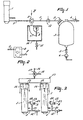
- FIG 1 shows only one of the teat cups to be connected automatically to the teats of an animal to be milked by means of a (non-shown) milking robot. Like the other teat cups, this teat cup 1 is connected to milk container means 3 via a milk line 2. As shown in this figure, the milk container means are constituted by a milk glass. The four milk lines 2 of the teat cups debouch into said milk glass 3, while the milk glass is furthermore connected via a valve 4 to the vacuum system of the milking implement. From the milk glass 3 the milk is discharged to a (non-shown) milk tank via a valve 5 by means of a pump 6. In each of the milk lines 2 there is included an auxiliary reservoir 7. In Figure 1 this provision is only represented for one milk line.
- the content of the auxiliary reservoir is larger than the to be expected quantity of foremilk that is obtained at the start of the milking via the relevant teat cup 1.
- the content of the auxiliary reservoir is preferably approximately two to three times as large as the to be expected quantity of foremilk.
- the connecting element 8 is constituted by a space to which the interrupted ends of a milk line 2 are connected. In the bottom of this space there is made an opening which is in direct connection with the auxiliary reservoir 7.
- both ends of the milk line 2 are connected to the connecting element 8, in a substantially horizontal plane, so as to face each other in a staggering position.
- a valve 12 is thereby disposed between the connecting element 8 and the milk glass 3.
- the auxiliary reservoir 7 is provided with an outlet valve 9 which closes off the auxiliary reservoir 7 because of the vacuum present in a milk line 2.
- the auxiliary reservoir 7 is no longer closed off by the outlet valve 9. Due to the pressure of the (fore)milk present in the auxiliary reservoir 7 the outlet valve 9 will easily deviate and the (fore)milk will flow into a collecting element 10.
- the (fore)milk collected in the collecting element 10 can be discharged via the valve 11 and a (non-shown) pump, in particular to an implement for supplying feed and/or beverage to an animal.
- the milk yielded by means of the teat cups will not directly flow through to the milk container means 3 due to the presence of the connecting element 8 in the milk line 2 and the opening made in the lower side of said connecting element which is in connection with the auxiliary reservoir 7, due to the fact that the connecting element constitutes a resistance for the milk stream. Said resistance is realized by the staggering interruption, in a substantially horizontal plane, in the milk line 2. Therefore the milk obtained first will fill first the auxiliary reservoir 7 via the opening at the lower side of the connecting element, while the subsequent milk stream will flow through the connecting element 8 to the milk glass 3. In practice it has appeared that the milk flowing from the teat cup 2 to the milk glass 3 does practically not mix with the foremilk present in the lower part of the auxiliary reservoir.
- the teat cups are connected in a customary manner to rinsing members by means of which a rinsing fluid is guided in the teat cups and possibly also over the edge thereof.
- a rinsing fluid By closing the valve 12 provided behind the connecting element 8, the rinsing fluid can be discharged directly via the auxiliary reservoir 7; thereby the valve 11 will in principle be opened. In this manner a very quick rinsing fluid discharge is possible, so that the teat cups can be cleaned easily and quickly after each milking run of an animal.
- drying air can be pressed through the teat cups and escape via the auxiliary reservoir 7.
- the teat cups and the milk line system When the teat cups and the milk line system have to be cleaned, the teat cups are connected in a customary manner to rinsing members and now also included in a rinsing line system. Like the (fore)milk, the rinsing fluid will first fill the auxiliary reservoir 7 and then be guided further to the milk glass 3 and be discharged via the valve 5 and the pump 6. In this manner the teat cups and the lines connected thereto including the milk glass 3 will be rinsed. When cleaning of the teat cups and the milk line system has ended, rinsing fluid will remain in the auxiliary reservoir 7.
- the rinsing fluid When the rinsing members are disconnected from the teat cups and consequently the teat cups are again in open connection with the open air, so that the vacuum is removed from the milk line 2, the rinsing fluid will get into the collecting element 10 via the outlet valve 9, in the same manner as described above for the (fore)milk present in the auxiliary reservoir, and will be discharged via the valve 11. Thereby the valve 12 is in its closed position.
- the rinsing fluid collected in the collecting element 10 can also be supplied as drinking-water to the implement for supplying feed and/or beverage to the animals.
- a holder 13 for cleaning means can be connected to the teat cups 1.
- the holder 13 for cleaning means comprises spraying members 14, by means of which the inside of the teat cups 1, the milk lines 2, as well as the upper edge 15 of the teat cups 1 can be cleaned.
- the cleaning fluid is supplied to the spraying members 14 via a line 16, connected to the holder 13 for cleaning means.
- a computer-controlled three-way valve 17 is included in the line 16. To the computer-controlled three-way valve 17 there is further connected a line 18 through which drying air can be pressed to the spraying members 14.
- each of the milk lines 2 there is further included a computer-controlled valve 12, by means of which a short rinsing fluid discharge line can be obtained by closing off the valve 12.
- the milk lines 2 between the teat cups 1 and the computer-controlled valves 12 have a length lying between 100 cm and 200 cm and preferably being 150 cm.
- a rinsing fluid discharge element 19 comprises a line 20, extending with a first portion 21 from a milk line 2 in upward direction. The first portion 21 merges into a second bent portion 22, whose end extends horizontally.
- the end of the second bent portion 22 is provided with an outlet valve 9 which is freely pivotable about a horizontal pivot shaft 23.
- the outlet valve 9 closes off the line 20 of the rinsing fluid discharge element 19 because of the vacuum present in the milk line 2. Due to the fact that the line 20 is disposed in upward direction relative to the milk line 2, there is not collected milk and/or foremilk in the line 20, like in the previous construction.
- the rinsing fluid discharge element 19 exclusively serves for discharging the rinsing fluid.
- the teat cups 1 as well as the first part of the milk lines 2 are cleaned by means of the holder 13 for cleaning means.
- cleaning fluid is sprayed over the edges 15 of the teat cups 1 by means of the spraying members 14 for cleaning the outside of the teat cups 1, while by means of the spraying members 14 there is also sprayed a cleaning fluid, such as a water-caustic solution, into the teat cups 1 and the milk lines 2.
- a cleaning fluid such as a water-caustic solution
- the computer-controlled three-way valve 16 is operated so that the line 18 is connected with the holder 13 for cleaning means.
- the spraying members 14 there is brought drying air into the teat cups 1 and the milk line 2.
- the rinsing fluid is pressed out of the teat cups 1 and the milk lines 2, such that by opening the outlet valves 9 the rinsing fluid is allowed to leave the milk lines 2. Due to the cleaning of the teat cups 1 and the milk lines 2 by blowing drying air, rinsing fluid residues are prevented from remaining in the teat cups and the milk lines 2, and from mixing with the milk, as a result thereof, during a next working run.
- the holder 13 for cleaning means is removed, the computer-controlled valves 12 are opened and the teat cups 1 can again be connected to the teats of an animal to be milked, after which the valves 9 close automatically because of the vacuum in the milk lines 2.
Abstract
Description
- The present invention relates to an implement for milking animals, such as cows, according to the preamble of claim 1, and already disclosed by US-A- 52 75 124.
- When milking animals in a suchlike implement, it is important that the cleaning takes place easily and quickly. For that reason, in accordance with the invention, the implement is characterized in that in at least one milk line, between a teat cup and a computer-controlled valve included in the relevant milk line, there is included a rinsing fluid discharge element for discharging the cleaning fluid supplied by the cleaning means. In this manner a very quick rinsing fluid discharge is possible, so that the teat cups can be cleaned easily and quickly after each milking run of an animal.
- In a particular embodiment the rinsing fluid discharge element comprises a closing element, which closes off the outlet opening of the rinsing fluid discharge element because of the vacuum present in the milk line. This closing element releases the outlet opening of the auxiliary reservoir when the teat cup is included in a rinsing line system only intended for cleaning the teat cup, or when the teat cup is included in a rinsing line system and rinsing of the teat cup and the milk line connected thereto is ended. In other words, when the milk line system has to be cleaned and a rinsing fluid is brought into the teat cup and the milk line connected thereto in a customary manner by means of rinsing members connected to a teat cup, because of the fact that the auxiliary reservoir is then, of course, filled with rinsing fluid, said rinsing fluid will have to be discharged as soon as the teat cup is disconnected from the rinsing member. In order to avoid that the rinsing fluid flowing out of the auxiliary reservoir each time gets onto the floor and flows away, the auxiliary reservoir has an outlet opening debouching into a collecting element. In other words, the rinsing fluid is collected in the auxiliary reservoir, in particular when said rinsing fluid does not contain chemical components that are harmful for the animals, but substantially consists of water containing milk residues if any. For that purpose, in accordance with the invention, the rinsing fluid discharged via the auxiliary reservoir is supplied to an implement for supplying feed and/or beverage to an animal. In this manner, insofar as water is used as a rinsing fluid, the water containing milk residues if any, flowing out of the auxiliary reservoir, needs not to be wasted.
- For a better understanding of the invention and to show how the same may be carried into effect, reference will now be made, by way of example, to the accompanying drawings, in which:
- Figure 1 shows schematically the milk line system between a teat cup and the milk container means;
- Figure 2 is a plan view of the connecting element, and
- Figure 3 shows schematically an embodiment of a milk line system including a short rinsing fluid discharge line.
-
- Figure 1 shows only one of the teat cups to be connected automatically to the teats of an animal to be milked by means of a (non-shown) milking robot. Like the other teat cups, this teat cup 1 is connected to milk container means 3 via a milk line 2. As shown in this figure, the milk container means are constituted by a milk glass. The four milk lines 2 of the teat cups debouch into said milk glass 3, while the milk glass is furthermore connected via a valve 4 to the vacuum system of the milking implement. From the milk glass 3 the milk is discharged to a (non-shown) milk tank via a valve 5 by means of a pump 6. In each of the milk lines 2 there is included an auxiliary reservoir 7. In Figure 1 this provision is only represented for one milk line. The content of the auxiliary reservoir is larger than the to be expected quantity of foremilk that is obtained at the start of the milking via the relevant teat cup 1. The content of the auxiliary reservoir is preferably approximately two to three times as large as the to be expected quantity of foremilk. Via a connecting element 8 the auxiliary reservoir 7 is in open connection with the relevant milk line 2. The connecting element 8 is constituted by a space to which the interrupted ends of a milk line 2 are connected. In the bottom of this space there is made an opening which is in direct connection with the auxiliary reservoir 7. As represented in Figure 2, both ends of the milk line 2 are connected to the connecting element 8, in a substantially horizontal plane, so as to face each other in a staggering position. A
valve 12 is thereby disposed between the connecting element 8 and the milk glass 3. - The auxiliary reservoir 7 is provided with an outlet valve 9 which closes off the auxiliary reservoir 7 because of the vacuum present in a milk line 2. When the
valve 12 is closed and the vacuum in the milk line 2 is removed, the auxiliary reservoir 7 is no longer closed off by the outlet valve 9. Due to the pressure of the (fore)milk present in the auxiliary reservoir 7 the outlet valve 9 will easily deviate and the (fore)milk will flow into acollecting element 10. The (fore)milk collected in thecollecting element 10 can be discharged via the valve 11 and a (non-shown) pump, in particular to an implement for supplying feed and/or beverage to an animal. - The milk yielded by means of the teat cups will not directly flow through to the milk container means 3 due to the presence of the connecting element 8 in the milk line 2 and the opening made in the lower side of said connecting element which is in connection with the auxiliary reservoir 7, due to the fact that the connecting element constitutes a resistance for the milk stream. Said resistance is realized by the staggering interruption, in a substantially horizontal plane, in the milk line 2. Therefore the milk obtained first will fill first the auxiliary reservoir 7 via the opening at the lower side of the connecting element, while the subsequent milk stream will flow through the connecting element 8 to the milk glass 3. In practice it has appeared that the milk flowing from the teat cup 2 to the milk glass 3 does practically not mix with the foremilk present in the lower part of the auxiliary reservoir.
- When only the teat cups have to be cleaned, the teat cups are connected in a customary manner to rinsing members by means of which a rinsing fluid is guided in the teat cups and possibly also over the edge thereof. By closing the
valve 12 provided behind the connecting element 8, the rinsing fluid can be discharged directly via the auxiliary reservoir 7; thereby the valve 11 will in principle be opened. In this manner a very quick rinsing fluid discharge is possible, so that the teat cups can be cleaned easily and quickly after each milking run of an animal. In a similar manner drying air can be pressed through the teat cups and escape via the auxiliary reservoir 7. When the teat cups and the milk line system have to be cleaned, the teat cups are connected in a customary manner to rinsing members and now also included in a rinsing line system. Like the (fore)milk, the rinsing fluid will first fill the auxiliary reservoir 7 and then be guided further to the milk glass 3 and be discharged via the valve 5 and the pump 6. In this manner the teat cups and the lines connected thereto including the milk glass 3 will be rinsed. When cleaning of the teat cups and the milk line system has ended, rinsing fluid will remain in the auxiliary reservoir 7. When the rinsing members are disconnected from the teat cups and consequently the teat cups are again in open connection with the open air, so that the vacuum is removed from the milk line 2, the rinsing fluid will get into thecollecting element 10 via the outlet valve 9, in the same manner as described above for the (fore)milk present in the auxiliary reservoir, and will be discharged via the valve 11. Thereby thevalve 12 is in its closed position. When it is ensured that the rinsing fluid does not contain chemical components that are harmful for the animals and only consists of water including milk residues if any, the rinsing fluid collected in the collectingelement 10 can also be supplied as drinking-water to the implement for supplying feed and/or beverage to the animals. - In order to make it possible to clean the teat cups 1 and the milk lines 2 after each milking run by means of a cleaning fluid, a holder 13 for cleaning means can be connected to the teat cups 1. The holder 13 for cleaning means comprises spraying
members 14, by means of which the inside of the teat cups 1, the milk lines 2, as well as theupper edge 15 of the teat cups 1 can be cleaned. The cleaning fluid is supplied to the sprayingmembers 14 via aline 16, connected to the holder 13 for cleaning means. A computer-controlled three-way valve 17 is included in theline 16. To the computer-controlled three-way valve 17 there is further connected a line 18 through which drying air can be pressed to the sprayingmembers 14. In each of the milk lines 2 there is further included a computer-controlledvalve 12, by means of which a short rinsing fluid discharge line can be obtained by closing off thevalve 12. The milk lines 2 between the teat cups 1 and the computer-controlledvalves 12 have a length lying between 100 cm and 200 cm and preferably being 150 cm. To each of the milk lines 2, between the teat cup 1 and the computer-controlledvalve 12, there is further connected a rinsingfluid discharge element 19. Said rinsingfluid discharge element 19 comprises a line 20, extending with afirst portion 21 from a milk line 2 in upward direction. Thefirst portion 21 merges into a second bent portion 22, whose end extends horizontally. The end of the second bent portion 22 is provided with an outlet valve 9 which is freely pivotable about a horizontal pivot shaft 23. During milking, the outlet valve 9 closes off the line 20 of the rinsingfluid discharge element 19 because of the vacuum present in the milk line 2. Due to the fact that the line 20 is disposed in upward direction relative to the milk line 2, there is not collected milk and/or foremilk in the line 20, like in the previous construction. The rinsingfluid discharge element 19 exclusively serves for discharging the rinsing fluid. - The function of the rinsing
fluid discharge element 19 will be explained in what follows: - After each milking run the teat cups 1 as well as the first part of the milk lines 2 are cleaned by means of the holder 13 for cleaning means. To that end cleaning fluid is sprayed over the
edges 15 of the teat cups 1 by means of the sprayingmembers 14 for cleaning the outside of the teat cups 1, while by means of the sprayingmembers 14 there is also sprayed a cleaning fluid, such as a water-caustic solution, into the teat cups 1 and the milk lines 2. After a fixed period of time the computer-controlledvalves 12 are automatically closed so that the teat cups 1 and the portions of the milk lines 2 located between the teat cups and the computer-controlledvalve 12 will completely be filled with cleaning fluid. Then the computer-controlled three-way valve 16 is operated so that the line 18 is connected with the holder 13 for cleaning means. In this manner, via the sprayingmembers 14, there is brought drying air into the teat cups 1 and the milk line 2. By means of the drying air the rinsing fluid is pressed out of the teat cups 1 and the milk lines 2, such that by opening the outlet valves 9 the rinsing fluid is allowed to leave the milk lines 2. Due to the cleaning of the teat cups 1 and the milk lines 2 by blowing drying air, rinsing fluid residues are prevented from remaining in the teat cups and the milk lines 2, and from mixing with the milk, as a result thereof, during a next working run. After the teat cups 1 and the milk lines 2 have been cleaned, the holder 13 for cleaning means is removed, the computer-controlledvalves 12 are opened and the teat cups 1 can again be connected to the teats of an animal to be milked, after which the valves 9 close automatically because of the vacuum in the milk lines 2.
Claims (9)
- An implement for milking animals, such as cows, comprising a milking parlour and a milking machine including teat cups (1) for automatically milking animals, and cleaning means for cleaning at least the teat cups (1) and the milk lines (2) connected thereto, characterized in that in at least one milk line (2), between a teat cup (1) and a computer-controlled valve (12) included in the relevant milk line (2), there is included a rinsing fluid discharge element (7, 19) for discharging the cleaning fluid supplied by the cleaning means.
- An implement as claimed in claim 1, characterized in that the rinsing fluid discharge element (7, 19) comprises a closing element (9), which closes off the outlet opening of the rinsing fluid discharge element (7, 19) because of the vacuum present in the milk line (2).
- An implement as claimed in claim 2, characterized in that the closing element (9) releases the outlet opening of the rinsing fluid discharge element (7, 19) when after milking a teat cup (1) and the short milk line (2) connected thereto are rinsed.
- An implement as claimed in any one of claims 1 to 3, characterized in that the rinsing fluid discharge element (7, 19) comprises a line (20) connected with one end to the milk line (2) and whose other end is provided with the closing element (9).
- An implement as claimed in claim 4, characterized in that the line (20) extends with a first portion (21) from the milk line (2) in upward direction, which first portion (21) merges into a second bent portion (22).
- An implement as claimed in claim 4 or 5, characterized in that the closing element (9), near the end of the second bent portion (22), is constituted by a freely pivotable outlet valve (9).
- An implement as claimed in any one of the preceding claims, characterized in that the cleaning means comprise a holder (13) for cleaning means including spraying members (14) capable of being connected to the teat cups (1).
- An implement as claimed in claim 7, characterized in that to the holder (13) for cleaning means there is connected a drying air line (18), by means of which, after cleaning, the rinsing fluid can be pressed out of the teat cups (1) and the short milk lines (2) to the rinsing fluid discharge element (7, 19).
- An implement as claimed in any one of the preceding claims, characterized in that the implement comprises a milking robot for automatically connecting the teat cups (1) to the teats of an animal to be milked, respectively disconnecting same therefrom.
Applications Claiming Priority (7)
| Application Number | Priority Date | Filing Date | Title |
|---|---|---|---|
| NL1001740 | 1995-11-24 | ||
| NL1001740 | 1995-11-24 | ||
| NL1002472 | 1996-02-28 | ||
| NL1002472 | 1996-02-28 | ||
| NL1004196 | 1996-10-04 | ||
| NL1004196A NL1004196C1 (en) | 1995-11-24 | 1996-10-04 | Device for milking animals. |
| EP96938556A EP0805622B2 (en) | 1995-11-24 | 1996-11-22 | An implement for milking animals |
Related Parent Applications (1)
| Application Number | Title | Priority Date | Filing Date |
|---|---|---|---|
| EP96938556A Division EP0805622B2 (en) | 1995-11-24 | 1996-11-22 | An implement for milking animals |
Publications (3)
| Publication Number | Publication Date |
|---|---|
| EP1084608A2 EP1084608A2 (en) | 2001-03-21 |
| EP1084608A3 EP1084608A3 (en) | 2002-03-13 |
| EP1084608B1 true EP1084608B1 (en) | 2003-07-02 |
Family
ID=27351118
Family Applications (2)
| Application Number | Title | Priority Date | Filing Date |
|---|---|---|---|
| EP00204559A Expired - Lifetime EP1084608B1 (en) | 1995-11-24 | 1996-11-22 | An implement for milking animals |
| EP96938556A Expired - Lifetime EP0805622B2 (en) | 1995-11-24 | 1996-11-22 | An implement for milking animals |
Family Applications After (1)
| Application Number | Title | Priority Date | Filing Date |
|---|---|---|---|
| EP96938556A Expired - Lifetime EP0805622B2 (en) | 1995-11-24 | 1996-11-22 | An implement for milking animals |
Country Status (10)
| Country | Link |
|---|---|
| US (1) | US5913281A (en) |
| EP (2) | EP1084608B1 (en) |
| JP (1) | JP3653100B2 (en) |
| AT (2) | ATE203367T1 (en) |
| CA (1) | CA2210630A1 (en) |
| DE (2) | DE69614092T3 (en) |
| DK (2) | DK0805622T4 (en) |
| ES (1) | ES2161381T3 (en) |
| NL (1) | NL1004196C1 (en) |
| WO (1) | WO1997018701A2 (en) |
Families Citing this family (17)
| Publication number | Priority date | Publication date | Assignee | Title |
|---|---|---|---|---|
| NL1006171C2 (en) * | 1997-05-30 | 1998-12-01 | Maasland Nv | Construction with a device for automatic milking of animals. |
| SE9704781D0 (en) | 1997-12-19 | 1997-12-19 | Alfa Laval Agri Ab | A method and apparatus for separating foremilk |
| NL1014780C2 (en) * | 2000-03-29 | 2001-02-20 | Idento Electronics Bv | Method and device for milking livestock. |
| NL1015525C2 (en) | 2000-06-26 | 2001-12-28 | Lely Entpr Ag | Device for milking animals. |
| SE520918C2 (en) * | 2001-03-14 | 2003-09-16 | Delaval Holding Ab | Apparatus for separating colostrum from subsequent rinsing water in an automated milking system |
| NL1019625C2 (en) * | 2001-12-20 | 2003-06-30 | Lely Entpr Ag | Device and teat cup for milking animals. |
| NL1020805C2 (en) * | 2002-06-06 | 2003-12-09 | Lely Entpr Ag | Method and device for performing measurements on milk obtained from the animal. |
| US20060249084A1 (en) * | 2003-06-11 | 2006-11-09 | Rawlin Grant T | Method and apparatus for collection of fluids |
| NL1025819C2 (en) † | 2004-03-26 | 2005-09-27 | Lely Entpr Ag | Method and device for milking a dairy animal. |
| WO2007045489A1 (en) * | 2005-10-20 | 2007-04-26 | Gea Westfaliasurge Gmbh | Milking device and milking method |
| NL1030475C2 (en) * | 2005-11-21 | 2007-05-22 | Maasland Nv | Device for milking animals. |
| NL1032570C2 (en) * | 2006-09-26 | 2008-03-27 | Maasland Nv | Method and device for milking a dairy animal and cleaning at least a part of a milking device for milking the dairy animal. |
| DE102006053602A1 (en) | 2006-11-14 | 2008-05-15 | Jakob Maier | Cleaning system for milking cups |
| EP2060169B1 (en) * | 2007-11-16 | 2014-12-24 | DeLaval Holding AB | Apparatus and method for cleaning a milking system |
| JP5327527B2 (en) * | 2008-05-12 | 2013-10-30 | オリオン機械株式会社 | Milking bucket cleaning device and connection structure |
| DE102009034234B4 (en) * | 2009-07-23 | 2013-06-13 | Wmf Württembergische Metallwarenfabrik Ag | Vending Machine |
| NL2012789B1 (en) * | 2014-05-09 | 2016-02-24 | Lely Patent Nv | Milking establishment. |
Family Cites Families (13)
| Publication number | Priority date | Publication date | Assignee | Title |
|---|---|---|---|---|
| US4061504A (en) * | 1976-05-21 | 1977-12-06 | Cornell Research Foundation, Inc. | Apparatus for cleaning automatic milking machines |
| SE406028B (en) * | 1976-05-21 | 1979-01-22 | Alfa Laval Ab | DEVICE FOR DISHING A TUB MILKING SYSTEM |
| US4190020A (en) † | 1978-01-03 | 1980-02-26 | Mezogazdasagi Foiskola, Kaposvar | Process and equipment for machine milking to provide sterile milk free from blood and pus |
| SU1281217A1 (en) † | 1985-05-07 | 1987-01-07 | Dorofeev Stanislav V | Apparatus for selecting the first portions of milk |
| AU598762B2 (en) * | 1985-11-01 | 1990-07-05 | Agresearch Limited | Improvements in milking machinery |
| SU1351543A1 (en) † | 1986-01-20 | 1987-11-15 | Гомельское Специальное Конструкторско-Технологическое Бюро Сейсмической Техники С Опытным Производством | Apparatus for automatic selection of the first portions of milk |
| SU1349735A1 (en) † | 1986-01-28 | 1987-11-07 | В.И.Корнеев | Apparatus for premilking treatment of udder and milking animals |
| US5275124A (en) * | 1989-02-27 | 1994-01-04 | C. Van Der Lely N.V. | Milking apparatus |
| NL193553C (en) * | 1989-02-27 | 2003-01-10 | Lely Entpr Ag | Milking installation. |
| NL8901339A (en) * | 1989-05-26 | 1990-12-17 | Multinorm Bv | DRAIN SYSTEM FOR MILK AND AN AUTOMATIC MILK SYSTEM WITH SUCH A DRAIN SYSTEM. |
| NL9301098A (en) * | 1993-06-24 | 1995-01-16 | Texas Industries Inc | Device for automatic milking of animals. |
| NL9301099A (en) * | 1993-06-24 | 1995-01-16 | Texas Industries Inc | Device for automatic milking of animals. |
| NL9500347A (en) * | 1994-05-19 | 1996-01-02 | Maasland Nv | Construction with device for milking animals and method for cleaning teat cups. |
-
1996
- 1996-10-04 NL NL1004196A patent/NL1004196C1/en not_active IP Right Cessation
- 1996-11-22 DE DE69614092T patent/DE69614092T3/en not_active Expired - Lifetime
- 1996-11-22 AT AT96938556T patent/ATE203367T1/en not_active IP Right Cessation
- 1996-11-22 ES ES96938556T patent/ES2161381T3/en not_active Expired - Lifetime
- 1996-11-22 EP EP00204559A patent/EP1084608B1/en not_active Expired - Lifetime
- 1996-11-22 DK DK96938556T patent/DK0805622T4/en active
- 1996-11-22 DE DE69628952T patent/DE69628952T2/en not_active Expired - Lifetime
- 1996-11-22 AT AT00204559T patent/ATE243928T1/en not_active IP Right Cessation
- 1996-11-22 WO PCT/NL1996/000464 patent/WO1997018701A2/en active IP Right Grant
- 1996-11-22 CA CA002210630A patent/CA2210630A1/en not_active Abandoned
- 1996-11-22 EP EP96938556A patent/EP0805622B2/en not_active Expired - Lifetime
- 1996-11-22 DK DK00204559T patent/DK1084608T3/en active
- 1996-11-22 JP JP51961897A patent/JP3653100B2/en not_active Expired - Fee Related
-
1997
- 1997-07-24 US US08/899,888 patent/US5913281A/en not_active Expired - Lifetime
Also Published As
| Publication number | Publication date |
|---|---|
| DE69628952T2 (en) | 2004-05-27 |
| WO1997018701A3 (en) | 1997-08-14 |
| EP0805622B2 (en) | 2006-10-18 |
| EP0805622A2 (en) | 1997-11-12 |
| DE69614092T3 (en) | 2007-04-05 |
| DK1084608T3 (en) | 2003-10-20 |
| EP1084608A2 (en) | 2001-03-21 |
| DK0805622T3 (en) | 2001-09-24 |
| EP0805622B1 (en) | 2001-07-25 |
| JP3653100B2 (en) | 2005-05-25 |
| ATE243928T1 (en) | 2003-07-15 |
| ATE203367T1 (en) | 2001-08-15 |
| ES2161381T3 (en) | 2001-12-01 |
| CA2210630A1 (en) | 1997-05-29 |
| DE69614092T2 (en) | 2002-03-21 |
| DE69628952D1 (en) | 2003-08-07 |
| DK0805622T4 (en) | 2007-02-12 |
| US5913281A (en) | 1999-06-22 |
| DE69614092D1 (en) | 2001-08-30 |
| NL1004196C1 (en) | 1997-05-27 |
| JPH10513064A (en) | 1998-12-15 |
| EP1084608A3 (en) | 2002-03-13 |
| WO1997018701A2 (en) | 1997-05-29 |
Similar Documents
| Publication | Publication Date | Title |
|---|---|---|
| EP1084608B1 (en) | An implement for milking animals | |
| US5080040A (en) | Milking plant | |
| AU602381B2 (en) | Method for cleaning a teat of a female animal, milking method and cup for use with above mentioned methods | |
| CA2394162C (en) | Method and apparatus for teat cup cleaning | |
| US3629005A (en) | Milking unit sanitizer | |
| WO2014209203A1 (en) | Arrangement for milking animals | |
| WO2004032608A1 (en) | A milking plant | |
| CA2370447A1 (en) | A cleaning device | |
| CA2529582C (en) | A milking device and a method of handling a milking device | |
| EP1169912B1 (en) | An implement for milking animals | |
| EP0626130B1 (en) | A construction for milking animals | |
| EP0626129B2 (en) | A construction for milking animals | |
| EP1905297B1 (en) | Method and implement for milking a dairy animal | |
| EP1321029B1 (en) | A device and a teat cup for milking animals | |
| CS204511B1 (en) | Device for milking the milking cows in the binding stal |
Legal Events
| Date | Code | Title | Description |
|---|---|---|---|
| PUAI | Public reference made under article 153(3) epc to a published international application that has entered the european phase |
Free format text: ORIGINAL CODE: 0009012 |
|
| AC | Divisional application: reference to earlier application |
Ref document number: 805622 Country of ref document: EP |
|
| AK | Designated contracting states |
Kind code of ref document: A2 Designated state(s): AT BE CH DE DK ES FR GB IE IT LI NL SE |
|
| PUAL | Search report despatched |
Free format text: ORIGINAL CODE: 0009013 |
|
| AK | Designated contracting states |
Kind code of ref document: A3 Designated state(s): AT BE CH DE DK ES FR GB IE IT LI NL SE |
|
| RIC1 | Information provided on ipc code assigned before grant |
Free format text: 7A 01J 5/017 A, 7A 01J 7/02 B |
|
| 17P | Request for examination filed |
Effective date: 20020703 |
|
| GRAH | Despatch of communication of intention to grant a patent |
Free format text: ORIGINAL CODE: EPIDOS IGRA |
|
| AKX | Designation fees paid |
Free format text: AT BE CH DE DK ES FR GB IE IT LI NL SE |
|
| GRAH | Despatch of communication of intention to grant a patent |
Free format text: ORIGINAL CODE: EPIDOS IGRA |
|
| GRAA | (expected) grant |
Free format text: ORIGINAL CODE: 0009210 |
|
| AC | Divisional application: reference to earlier application |
Ref document number: 0805622 Country of ref document: EP Kind code of ref document: P |
|
| AK | Designated contracting states |
Designated state(s): AT BE CH DE DK ES FR GB IE IT LI NL SE |
|
| PG25 | Lapsed in a contracting state [announced via postgrant information from national office to epo] |
Ref country code: IT Free format text: LAPSE BECAUSE OF FAILURE TO SUBMIT A TRANSLATION OF THE DESCRIPTION OR TO PAY THE FEE WITHIN THE PRESCRIBED TIME-LIMIT;WARNING: LAPSES OF ITALIAN PATENTS WITH EFFECTIVE DATE BEFORE 2007 MAY HAVE OCCURRED AT ANY TIME BEFORE 2007. THE CORRECT EFFECTIVE DATE MAY BE DIFFERENT FROM THE ONE RECORDED. Effective date: 20030702 Ref country code: CH Free format text: LAPSE BECAUSE OF FAILURE TO SUBMIT A TRANSLATION OF THE DESCRIPTION OR TO PAY THE FEE WITHIN THE PRESCRIBED TIME-LIMIT Effective date: 20030702 Ref country code: AT Free format text: LAPSE BECAUSE OF FAILURE TO SUBMIT A TRANSLATION OF THE DESCRIPTION OR TO PAY THE FEE WITHIN THE PRESCRIBED TIME-LIMIT Effective date: 20030702 Ref country code: LI Free format text: LAPSE BECAUSE OF FAILURE TO SUBMIT A TRANSLATION OF THE DESCRIPTION OR TO PAY THE FEE WITHIN THE PRESCRIBED TIME-LIMIT Effective date: 20030702 Ref country code: BE Free format text: LAPSE BECAUSE OF FAILURE TO SUBMIT A TRANSLATION OF THE DESCRIPTION OR TO PAY THE FEE WITHIN THE PRESCRIBED TIME-LIMIT Effective date: 20030702 |
|
| REG | Reference to a national code |
Ref country code: GB Ref legal event code: FG4D |
|
| REG | Reference to a national code |
Ref country code: CH Ref legal event code: EP |
|
| REG | Reference to a national code |
Ref country code: IE Ref legal event code: FG4D |
|
| REF | Corresponds to: |
Ref document number: 69628952 Country of ref document: DE Date of ref document: 20030807 Kind code of ref document: P |
|
| REG | Reference to a national code |
Ref country code: SE Ref legal event code: TRGR |
|
| PG25 | Lapsed in a contracting state [announced via postgrant information from national office to epo] |
Ref country code: ES Free format text: LAPSE BECAUSE OF FAILURE TO SUBMIT A TRANSLATION OF THE DESCRIPTION OR TO PAY THE FEE WITHIN THE PRESCRIBED TIME-LIMIT Effective date: 20031013 |
|
| PGFP | Annual fee paid to national office [announced via postgrant information from national office to epo] |
Ref country code: GB Payment date: 20031119 Year of fee payment: 8 |
|
| PG25 | Lapsed in a contracting state [announced via postgrant information from national office to epo] |
Ref country code: IE Free format text: LAPSE BECAUSE OF NON-PAYMENT OF DUE FEES Effective date: 20031124 |
|
| REG | Reference to a national code |
Ref country code: CH Ref legal event code: PL |
|
| ET | Fr: translation filed | ||
| PLBE | No opposition filed within time limit |
Free format text: ORIGINAL CODE: 0009261 |
|
| STAA | Information on the status of an ep patent application or granted ep patent |
Free format text: STATUS: NO OPPOSITION FILED WITHIN TIME LIMIT |
|
| 26N | No opposition filed |
Effective date: 20040405 |
|
| REG | Reference to a national code |
Ref country code: IE Ref legal event code: MM4A |
|
| PG25 | Lapsed in a contracting state [announced via postgrant information from national office to epo] |
Ref country code: GB Free format text: LAPSE BECAUSE OF NON-PAYMENT OF DUE FEES Effective date: 20041122 |
|
| GBPC | Gb: european patent ceased through non-payment of renewal fee |
Effective date: 20041122 |
|
| PGFP | Annual fee paid to national office [announced via postgrant information from national office to epo] |
Ref country code: DK Payment date: 20131125 Year of fee payment: 18 |
|
| PGFP | Annual fee paid to national office [announced via postgrant information from national office to epo] |
Ref country code: SE Payment date: 20131127 Year of fee payment: 18 Ref country code: FR Payment date: 20131118 Year of fee payment: 18 |
|
| PGFP | Annual fee paid to national office [announced via postgrant information from national office to epo] |
Ref country code: NL Payment date: 20131126 Year of fee payment: 18 |
|
| PGFP | Annual fee paid to national office [announced via postgrant information from national office to epo] |
Ref country code: DE Payment date: 20141128 Year of fee payment: 19 |
|
| REG | Reference to a national code |
Ref country code: NL Ref legal event code: V1 Effective date: 20150601 |
|
| REG | Reference to a national code |
Ref country code: DK Ref legal event code: EBP Effective date: 20141130 |
|
| REG | Reference to a national code |
Ref country code: SE Ref legal event code: EUG |
|
| PG25 | Lapsed in a contracting state [announced via postgrant information from national office to epo] |
Ref country code: SE Free format text: LAPSE BECAUSE OF NON-PAYMENT OF DUE FEES Effective date: 20141123 |
|
| REG | Reference to a national code |
Ref country code: FR Ref legal event code: ST Effective date: 20150731 |
|
| PG25 | Lapsed in a contracting state [announced via postgrant information from national office to epo] |
Ref country code: NL Free format text: LAPSE BECAUSE OF NON-PAYMENT OF DUE FEES Effective date: 20150601 |
|
| PG25 | Lapsed in a contracting state [announced via postgrant information from national office to epo] |
Ref country code: DK Free format text: LAPSE BECAUSE OF NON-PAYMENT OF DUE FEES Effective date: 20141130 |
|
| PG25 | Lapsed in a contracting state [announced via postgrant information from national office to epo] |
Ref country code: FR Free format text: LAPSE BECAUSE OF NON-PAYMENT OF DUE FEES Effective date: 20141201 |
|
| REG | Reference to a national code |
Ref country code: DE Ref legal event code: R119 Ref document number: 69628952 Country of ref document: DE |
|
| PG25 | Lapsed in a contracting state [announced via postgrant information from national office to epo] |
Ref country code: DE Free format text: LAPSE BECAUSE OF NON-PAYMENT OF DUE FEES Effective date: 20160601 |