EP1084331B1 - Method and device to monitor the functioning of a catalyst in an internal combustion engine - Google Patents
Method and device to monitor the functioning of a catalyst in an internal combustion engine Download PDFInfo
- Publication number
- EP1084331B1 EP1084331B1 EP99915512A EP99915512A EP1084331B1 EP 1084331 B1 EP1084331 B1 EP 1084331B1 EP 99915512 A EP99915512 A EP 99915512A EP 99915512 A EP99915512 A EP 99915512A EP 1084331 B1 EP1084331 B1 EP 1084331B1
- Authority
- EP
- European Patent Office
- Prior art keywords
- catalyst
- variable
- internal combustion
- combustion engine
- exhaust
- Prior art date
- Legal status (The legal status is an assumption and is not a legal conclusion. Google has not performed a legal analysis and makes no representation as to the accuracy of the status listed.)
- Expired - Lifetime
Links
Images


Classifications
-
- F—MECHANICAL ENGINEERING; LIGHTING; HEATING; WEAPONS; BLASTING
- F01—MACHINES OR ENGINES IN GENERAL; ENGINE PLANTS IN GENERAL; STEAM ENGINES
- F01N—GAS-FLOW SILENCERS OR EXHAUST APPARATUS FOR MACHINES OR ENGINES IN GENERAL; GAS-FLOW SILENCERS OR EXHAUST APPARATUS FOR INTERNAL COMBUSTION ENGINES
- F01N9/00—Electrical control of exhaust gas treating apparatus
- F01N9/005—Electrical control of exhaust gas treating apparatus using models instead of sensors to determine operating characteristics of exhaust systems, e.g. calculating catalyst temperature instead of measuring it directly
-
- F—MECHANICAL ENGINEERING; LIGHTING; HEATING; WEAPONS; BLASTING
- F01—MACHINES OR ENGINES IN GENERAL; ENGINE PLANTS IN GENERAL; STEAM ENGINES
- F01N—GAS-FLOW SILENCERS OR EXHAUST APPARATUS FOR MACHINES OR ENGINES IN GENERAL; GAS-FLOW SILENCERS OR EXHAUST APPARATUS FOR INTERNAL COMBUSTION ENGINES
- F01N11/00—Monitoring or diagnostic devices for exhaust-gas treatment apparatus, e.g. for catalytic activity
- F01N11/007—Monitoring or diagnostic devices for exhaust-gas treatment apparatus, e.g. for catalytic activity the diagnostic devices measuring oxygen or air concentration downstream of the exhaust apparatus
-
- F—MECHANICAL ENGINEERING; LIGHTING; HEATING; WEAPONS; BLASTING
- F02—COMBUSTION ENGINES; HOT-GAS OR COMBUSTION-PRODUCT ENGINE PLANTS
- F02P—IGNITION, OTHER THAN COMPRESSION IGNITION, FOR INTERNAL-COMBUSTION ENGINES; TESTING OF IGNITION TIMING IN COMPRESSION-IGNITION ENGINES
- F02P15/00—Electric spark ignition having characteristics not provided for in, or of interest apart from, groups F02P1/00 - F02P13/00 and combined with layout of ignition circuits
- F02P15/001—Ignition installations adapted to specific engine types
- F02P15/003—Layout of ignition circuits for gas turbine plants
-
- F—MECHANICAL ENGINEERING; LIGHTING; HEATING; WEAPONS; BLASTING
- F02—COMBUSTION ENGINES; HOT-GAS OR COMBUSTION-PRODUCT ENGINE PLANTS
- F02P—IGNITION, OTHER THAN COMPRESSION IGNITION, FOR INTERNAL-COMBUSTION ENGINES; TESTING OF IGNITION TIMING IN COMPRESSION-IGNITION ENGINES
- F02P9/00—Electric spark ignition control, not otherwise provided for
- F02P9/002—Control of spark intensity, intensifying, lengthening, suppression
-
- F—MECHANICAL ENGINEERING; LIGHTING; HEATING; WEAPONS; BLASTING
- F01—MACHINES OR ENGINES IN GENERAL; ENGINE PLANTS IN GENERAL; STEAM ENGINES
- F01N—GAS-FLOW SILENCERS OR EXHAUST APPARATUS FOR MACHINES OR ENGINES IN GENERAL; GAS-FLOW SILENCERS OR EXHAUST APPARATUS FOR INTERNAL COMBUSTION ENGINES
- F01N2550/00—Monitoring or diagnosing the deterioration of exhaust systems
- F01N2550/02—Catalytic activity of catalytic converters
-
- F—MECHANICAL ENGINEERING; LIGHTING; HEATING; WEAPONS; BLASTING
- F01—MACHINES OR ENGINES IN GENERAL; ENGINE PLANTS IN GENERAL; STEAM ENGINES
- F01N—GAS-FLOW SILENCERS OR EXHAUST APPARATUS FOR MACHINES OR ENGINES IN GENERAL; GAS-FLOW SILENCERS OR EXHAUST APPARATUS FOR INTERNAL COMBUSTION ENGINES
- F01N2560/00—Exhaust systems with means for detecting or measuring exhaust gas components or characteristics
- F01N2560/02—Exhaust systems with means for detecting or measuring exhaust gas components or characteristics the means being an exhaust gas sensor
- F01N2560/023—Exhaust systems with means for detecting or measuring exhaust gas components or characteristics the means being an exhaust gas sensor for measuring or detecting HC
-
- F—MECHANICAL ENGINEERING; LIGHTING; HEATING; WEAPONS; BLASTING
- F01—MACHINES OR ENGINES IN GENERAL; ENGINE PLANTS IN GENERAL; STEAM ENGINES
- F01N—GAS-FLOW SILENCERS OR EXHAUST APPARATUS FOR MACHINES OR ENGINES IN GENERAL; GAS-FLOW SILENCERS OR EXHAUST APPARATUS FOR INTERNAL COMBUSTION ENGINES
- F01N3/00—Exhaust or silencing apparatus having means for purifying, rendering innocuous, or otherwise treating exhaust
- F01N3/08—Exhaust or silencing apparatus having means for purifying, rendering innocuous, or otherwise treating exhaust for rendering innocuous
- F01N3/10—Exhaust or silencing apparatus having means for purifying, rendering innocuous, or otherwise treating exhaust for rendering innocuous by thermal or catalytic conversion of noxious components of exhaust
- F01N3/18—Exhaust or silencing apparatus having means for purifying, rendering innocuous, or otherwise treating exhaust for rendering innocuous by thermal or catalytic conversion of noxious components of exhaust characterised by methods of operation; Control
- F01N3/22—Control of additional air supply only, e.g. using by-passes or variable air pump drives
-
- Y—GENERAL TAGGING OF NEW TECHNOLOGICAL DEVELOPMENTS; GENERAL TAGGING OF CROSS-SECTIONAL TECHNOLOGIES SPANNING OVER SEVERAL SECTIONS OF THE IPC; TECHNICAL SUBJECTS COVERED BY FORMER USPC CROSS-REFERENCE ART COLLECTIONS [XRACs] AND DIGESTS
- Y02—TECHNOLOGIES OR APPLICATIONS FOR MITIGATION OR ADAPTATION AGAINST CLIMATE CHANGE
- Y02A—TECHNOLOGIES FOR ADAPTATION TO CLIMATE CHANGE
- Y02A50/00—TECHNOLOGIES FOR ADAPTATION TO CLIMATE CHANGE in human health protection, e.g. against extreme weather
- Y02A50/20—Air quality improvement or preservation, e.g. vehicle emission control or emission reduction by using catalytic converters
-
- Y—GENERAL TAGGING OF NEW TECHNOLOGICAL DEVELOPMENTS; GENERAL TAGGING OF CROSS-SECTIONAL TECHNOLOGIES SPANNING OVER SEVERAL SECTIONS OF THE IPC; TECHNICAL SUBJECTS COVERED BY FORMER USPC CROSS-REFERENCE ART COLLECTIONS [XRACs] AND DIGESTS
- Y02—TECHNOLOGIES OR APPLICATIONS FOR MITIGATION OR ADAPTATION AGAINST CLIMATE CHANGE
- Y02T—CLIMATE CHANGE MITIGATION TECHNOLOGIES RELATED TO TRANSPORTATION
- Y02T10/00—Road transport of goods or passengers
- Y02T10/10—Internal combustion engine [ICE] based vehicles
- Y02T10/40—Engine management systems
Definitions
- the invention relates to a method and a device to monitor the functionality of one in the exhaust system Internal combustion engine arranged catalyst according to the The preamble of claims 1 and 20.
- a method for catalyst monitoring known for Otto engines is based on the evaluation of the relationship between the oxygen storage capacity and the degree of conversion of a Three-way catalyst.
- Such a method is e.g. out known from DE 195 36 252; two oxygen or Lambda probes used, one upstream and one downstream of the Catalyst. This procedure can only be used when the lambda control is active and the catalytic converter has reached its operating temperature.
- the evaluation of the Lambda probe signals only allow indirect catalyst monitoring, where the correlation between oxygen storage capacity and degree of conversion of the catalyst is not is very good. That is why this procedure is just like that from DE 24 44 334 known to the diagnosis relatively large Conversion degree differences limited, which means only one severe deterioration of the catalyst can be diagnosed is. To diagnose minor catalyst deterioration, how they require strict emission limits these methods are not suitable.
- DE 195 37 778 discloses a method for monitoring the function of a NO x -reducing catalytic converter of a diesel internal combustion engine, in which fuel is metered in upstream of the catalytic converter as a reducing agent.
- a sensor for the hydrocarbon concentration in the exhaust gas is provided downstream of the catalyst in order to be able to detect a decrease in the catalytic reduction on the basis of increased hydrocarbon concentrations in the exhaust gas.
- the functionality is checked of the catalyst during the heating phase of the internal combustion engine. Because during the heating phase of the internal combustion engine the largest emission of pollutants emitted is a functional check of the catalyst in this Time period is particularly significant. On the other hand, it falls due to the higher pollutant concentration in the exhaust gas behind the Catalyst easier during the heating phase, changes in diagnose the functionality of the catalyst.
- the basic idea of the method according to the invention and that of the invention Device is based on the relationship between the degree of conversion or the emission level of a Exhaust component behind a catalyst to be monitored and the thermal properties, i.e. the temperature, the catalyst.
- the degree of conversion of the catalyst depends directly depending on its temperature. This dependency is changing with the aging of the catalyst. The degree of conversion gets worse with age of the catalyst. This Change in the dependency of the degree of conversion of the catalyst of its temperature with aging thus provides one way to check the catalytic converter for its functionality to monitor.
- the thermal property of the catalyst can be determined by the Solid state temperature of the catalyst itself or by the heat supplied to the catalyst is expressed.
- the latter can be upstream by determining the exhaust gas temperature of the catalyst and determination of the supplied to the catalyst Volume flow and subsequent calculation of the Catalyst supplied heat from exhaust gas temperature, volume flow and heat capacity of the exhaust gas.
- An energy supply by a possibly existing catalyst heating naturally also be taken into account.
- the exhaust gas temperature upstream of the catalyst using a Model calculated from operating parameters of the internal combustion engine become.
- the heat supplied to the catalytic converter continues preferably only determined if after a start the Internal combustion engine no longer has latent heat for evaporation is taken up by condensates in the catalyst.
- the catalyst is preferably monitored on the basis of measurements of a pollutant component, in particular carbon monoxide (CO), hydrocarbon (HC) or nitrogen oxides NO x .
- a pollutant component in particular carbon monoxide (CO), hydrocarbon (HC) or nitrogen oxides NO x .
- CO carbon monoxide
- HC hydrocarbon
- NO x nitrogen oxides
- the concentration of a pollutant component downstream of the catalyst measured in the exhaust gas are calculated.
- the embodiment of the method according to the invention is then when the catalyst temperature for a given degree of conversion is above a threshold, a lack of catalyst function recognized. Alternatively, this is also possible if a minimum degree of conversion at a given catalyst temperature is not reached.
- a non-functioning catalytic converter can be recognized in that the energy required to convert the degree of conversion of the catalytic converter from an initial value ⁇ i , for example 20%, to an end value ⁇ f , for example to increase 60%, is determined.
- the energy required to achieve the conversion degree increase ⁇ f - ⁇ i which must be supplied to the catalyst in the form of heat, is higher for an aged, non-functional catalyst than for a new, functional catalyst.
- the mean value of these energies also increases with the aging of the catalyst.
- the product of the mean value of the energy and the energy supplied is therefore a measure of the warm-up behavior of the catalytic converter and thus of its functionality.
- the catalyst diagnosis can be carried out in a simple manner by setting a threshold value for this product. If the threshold is exceeded, the catalytic converter is recognized as not functioning.
- the diagnostic threshold is preferably possible to select the diagnostic threshold as a function of temperature values of the internal combustion engine, such as, for example, cooling water temperature, intake air temperature, outside temperature or exhaust gas temperature when the internal combustion engine is started.
- the driving profile of a vehicle with which the internal combustion engine is equipped which can influence the heating of the catalytic converter, can be taken into account by a correction factor.
- the pollutant concentration upstream of the catalyst is not measured; instead, only the concentration of one of the pollutant components behind the catalytic converter is measured.
- the heat supplied to the catalytic converter or the change in the solid state temperature of the catalytic converter is determined, which is necessary in order to reduce the concentration of the pollutant component to be monitored from an initial value [i] i to an end value [i] f . Since the concentration is not in itself a direct measure of the amount of pollutant emitted, it is linked to the amount of exhaust gas and the mass of the pollutant component is determined. The better the heating behavior of the catalyst, the lower the mass which is emitted during the application of a given heat or during a predetermined change in the solid temperature of the catalyst.
- the catalytic converter is recognized as not functioning.
- the emitted mass is preferably multiplied by the mean supplied thermal energy in order to take into account the time course of the energy supply, such as load influences.
- the product of the mass emitted and the energy supplied is then a measure of the functionality of the catalytic converter, and if a threshold value is exceeded, the catalytic converter is recognized as defective.
- the diagnostic threshold is preferably also defined here as a function of temperature values of the internal combustion engine, such as cooling water temperature, intake air temperature, outside temperature or exhaust gas temperature when the internal combustion engine is started.
- the driving profile of a vehicle with which the internal combustion engine is equipped can also be taken into account by a correction factor during the method.
- inventive method and the device according to the invention for all types of catalysts such as reduction catalysts, oxidation catalysts, in particular regulated three-way catalysts, storage catalysts or adsorbers, as well as for gasoline and diesel engines are applicable.
- an internal combustion engine 1 has an intake tract 2 as well as an exhaust tract 3. Your business is run by a Control device 4 controlled or regulated.
- the control unit 4 becomes the measured value of an intake air mass sensor 5 supplied, which is arranged in the intake tract 2 of the internal combustion engine 1 and detects the intake air mass flow.
- the control unit 4 further controls the injection of the fuel via injection valves 6 in the intake tract 3 and detected by means of a lambda probe 7 the oxygen content of the exhaust gas, to regulate the operation of the internal combustion engine.
- a catalytic converter 15 is arranged, the functionality of which i.e. Degree of conversion should be monitored.
- the degree of conversion ⁇ of a catalyst depends directly on the temperature of the catalyst T cat . This relationship is shown in FIG. 2.
- Curve 13 shows the temperature dependence of the degree of conversion ⁇ of a new catalyst.
- Curve 14 describes an old inoperative catalyst. With increasing catalyst temperature T cat , ⁇ increases up to a maximum value. The course above the temperature at which the maximum value is reached depends on the catalyst used. It is approximately constant with a three-way catalytic converter, but decreases, for example, with a denitrification catalytic converter.
- the catalyst temperature T cat required for a certain degree of conversion ⁇ i increases, and the maximum degree of conversion ⁇ i, max decreases; the curve widens, as can be seen in FIG. 2.
- the change in the degree of conversion as a function of the temperature during aging thus offers a possibility of monitoring the functionality of the catalytic converter.
- a pollutant concentration sensor 8 is arranged upstream of the catalytic converter 15 and a pollutant concentration sensor 10 is arranged downstream of the catalytic converter, which measurements depend on the concentration of the pollutant component, e.g. the hydrocarbons (HC) deliver the control unit 4. There they are converted into the pollutant volume concentration using a mathematical function or a map.
- planar exhaust gas sensors which show a change in the electrical conductivity of a metal oxide (eg doped SrTiO 3 ) as a measurement signal.
- Exhaust gas sensors are also conceivable which use a solid electrolyte (eg stabilized ZrO 2 or CeO 2 ) as a measuring element.
- the relationship ⁇ i (T cat ) is evaluated directly by measuring the solid state temperature of the catalytic converter 15 with the temperature sensor 9 while the engine is warming up and for this purpose the degree of conversion ⁇ is determined from the signals from the pollutant concentration sensors 8, 9. Given the degree of conversion ⁇ diag , a new catalyst has a much lower temperature T new than an older catalyst. If, as can be seen in FIG. 2, the temperature T alt for the given degree of conversion ⁇ diag lies above a temperature threshold T diag , the catalyst is recognized as defective. Alternatively, the degree of conversion ⁇ to a given temperature T diag can also be determined and the catalyst can be recognized as defective if it falls below a predetermined threshold value ⁇ diag .
- FIG. 3 and 4 another embodiment of the Invention described. Elements corresponding to those of FIG. 1 are identified by the same reference numerals reference is made here to the description of FIG. 1.
- the difference 1 is not a temperature sensor 9 provided on the catalyst 15. Instead, the temperature the exhaust gas upstream of the catalyst with a temperature sensor 9 detected by the control unit 4. Via a secondary air pump 11 becomes the exhaust gas upstream of the catalyst 15 a secondary air mass flow supplied by a secondary air mass sensor 12 is measured, the measured value is supplied to the control device 4.
- the dependence of the degree of conversion on the energy supplied to the catalyst is used for the diagnosis in this case.
- the energy for heating the catalyst is supplied to it by the exhaust gas in the form of heat.
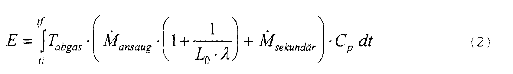
- This heat can be determined from the exhaust gas temperature upstream of the catalytic converter and the exhaust gas mass flow fed to the catalytic converter using the following equation: where T exhaust gas is the exhaust gas temperature upstream of the catalytic converter, M ⁇ intake is the intake air mass flow , M luft secondary is the secondary air mass flow, C p is the heat capacity of the exhaust gas at constant pressure, ⁇ is the air ratio and L 0 is the air mass per fuel mass unit with stoichometric combustion.
- the heat ⁇ Q E ⁇ f - E ⁇ i , which is necessary to increase the degree of conversion of the catalyst from an initial value ⁇ i (heat E ⁇ i ) to a final value ⁇ f (heat E ⁇ f ), is higher for an aged catalyst than for a new catalyst, as can be seen in FIG. 4.
- the curves shown in FIG. 4 correspond to those of FIG. 2, with the difference that they are plotted over the heat supplied to the catalyst 15 instead of over the solid temperature.
- the energies E ⁇ i and E ⁇ f necessary to achieve ⁇ i and ⁇ f are also higher with an aged catalyst than with a new catalyst.
- ⁇ th 0.5 (E ⁇ i + E ⁇ f ) also increases with the aging of the catalyst.
- the product of the mean value and the supplied heat ⁇ Q is therefore a useful measure of the warm-up behavior of the catalytic converter and thus of its functionality.
- the catalyst diagnosis can be carried out in a simple manner by setting a threshold value for the product. If the threshold is exceeded, the catalytic converter is recognized as defective.
- the thermal ones Boundary conditions of the system are important if you consider the heat supplied to the catalyst as a measure of its heating used.
- the diagnostic threshold preferably as a function temperature values of the internal combustion engine, e.g. Cooling water temperature, Intake temperature, outside temperature or exhaust gas temperature selected when starting the internal combustion engine become.
- the control device 4 contains a suitable one Map. Next, the driving profile of the vehicle speed of a vehicle in which the internal combustion engine is installed is, by a correction factor in the control unit 4th filed can be taken into account.
- FIG. 5 shows measurement results which demonstrate the method according to the invention using the example of the oxidation of hydrocarbons with a three-way catalyst.
- the measurements were carried out on an engine test bench, the structure corresponds to that of FIG. 3.
- the internal combustion engine was started from a cold state (300 ° K) at different constant speeds in order to generate different catalyst heating profiles.
- the determination of the hydrocarbon concentration upstream and downstream of the catalyst was carried out using a flame ionization detector (FID).
- Two catalysts were examined.
- the new catalytic converter, measurement curve 13 has an emission of 50 mgHC per mile after the FTP 75 driving cycle.
- the aged catalyst on trace 14 reaches 100 mgHC per mile.
- the two catalysts can be distinguished well using the method according to the invention, as shown in FIG. 5.
- the device of this exemplary embodiment corresponds to the device of FIG. 3.
- the heat which must be supplied to the catalyst is preferably determined in order to increase the concentration [i] according to cat.
- the pollutant component i to be monitored from an initial value [i] i to lower an end value [i] f .
- the concentration in particular the volume concentration
- M i i is the molar mass of the component
- M exhaust correspond to the molecular weight of the exhaust gas and all other terms of the equation (2).
- mass i is multiplied by the mean thermal energy E th as in the previous exemplary embodiment.
- E th is again a measure of the functionality of the catalyst. If a threshold value is exceeded, the catalytic converter is recognized as defective.
- the diagnostic threshold is defined as a function of temperature values of the internal combustion engine, such as cooling water temperature, intake air temperature, outside temperature or exhaust gas temperature of the internal combustion engine, before commissioning and stored in a map in control unit 4.
- the driving profile of a vehicle equipped with the internal combustion engine can in turn be taken into account during the diagnosis by a speed-dependent correction factor.
- Fig. 7 measurement results are shown, the application of the process using the example of the oxidation of hydrocarbons demonstrate in a three-way catalyst.
- the Measurements were taken on a roller dynamometer, the setup corresponds to that of FIG. 3 without the pollutant concentration sensor 8 upstream of the catalyst.
- the pollutant concentration sensor 10 downstream of the catalyst 15 is in this Example of a resistive planar sensor.
- Test Nos. 1 2 and 5 became a new catalyst in the tests 3, 4 and 6 of Fig. 7, an old catalyst was examined.
- tests 1 and 2 or 3 and 4 were successive Go through FTP 75 driving cycles, after these tests the engine was idle for 60 s in tests 5 and 6, respectively held.
- the tests pass with the aged catalyst clearly the threshold of 110 g kJ, while the tests with the new catalyst are clearly below Show values. This enables an old, out of order catalyst from a new one to distinguish.
- the result of the functional check can be given to the leader of the Internal combustion engine 1 or a vehicle equipped therewith signaled via a warning device (not shown) become.
- the control device 4 can have a memory (not shown) in which a statement about the Functionality of the internal combustion engine 1 is filed, the e.g. can be read out during maintenance.
Description
Die Erfindung betrifft ein Verfahren und eine Vorrichtung
zum Überwachen der Funktionsfähigkeit eines im Abgastrakt einer
Brennkraftmaschine angeordneten Katalysators gemäß dem
Oberbegriff der Patentansprüche 1 und 20.The invention relates to a method and a device
to monitor the functionality of one in the exhaust system
Internal combustion engine arranged catalyst according to the
The preamble of
Die Abgasnachbehandlung bei Brennkraftmaschinen erfolgt heutzutage üblicherweise mit einem oder mehreren Katalysatoren in der Auspuffanlage der Brennkraftmaschine. Strenge Emissionsgrenzwerte für Schadstoffemissionen von Brennkraftmaschinen, insbesondere in Fahrzeugen, machen die zuverlässige Überwachung des eingesetzten Katalysators erforderlich. Von solchen Diagnoseverfahren wird verlangt, daß sie die kontinuierliche Überprüfung des Katalysators im Betrieb ermöglichen, auch als On-Board-Diagnose bezeichnet.The exhaust gas aftertreatment in internal combustion engines nowadays usually takes place with one or more catalysts in the exhaust system of the internal combustion engine. Strict emission limit values for pollutant emissions from internal combustion engines, especially in vehicles, require reliable monitoring of the catalyst used. Of such diagnostic procedure requires that they allow continuous monitoring of the catalyst during operation, also referred to as O n- D B oard- iagnosis.
Ein für Otto-Motoren bekanntes Verfahren zur Katalysatorüberwachung basiert auf der Auswertung des Zusammenhangs zwischen dem Sauerstoffspeichervermögen und dem Konvertierungsgrad eines Dreiwege-Katalysators. Ein solches Verfahren ist z.B. aus der DE 195 36 252 bekannt; dabei werden zwei Sauerstoff- oder Lambda-Sonden eingesetzt, eine stromauf und eine stromab des Katalysators. Dieses Verfahren kann nur dann angewendet werden, wenn die Lambda-Regelung aktiv ist und der Katalysator seine Betriebstemperatur erreicht hat. Die Auswertung der Lambdasondensignale erlaubt nur eine indirekte Katalysatorüberwachung, wobei die Korrelation zwischen Sauerstoffspeichervermögen und Konvertierungsgrad des Katalysators nicht sehr gut ist. Deshalb ist dieses Verfahren, ebenso wie das aus DE 24 44 334 bekannte auf die Diagnose relativ großer Konvertierungsgraddifferenzen begrenzt, wodurch nur eine starke Verschlechterung des Katalysators diagnostizierbar ist. Zur Diagnose einer geringen Katalysatorverschlechterung, wie sie strenge Emissionsgrenzwerte erforderlich machen, sind diese Verfahren nicht tauglich.A method for catalyst monitoring known for Otto engines is based on the evaluation of the relationship between the oxygen storage capacity and the degree of conversion of a Three-way catalyst. Such a method is e.g. out known from DE 195 36 252; two oxygen or Lambda probes used, one upstream and one downstream of the Catalyst. This procedure can only be used when the lambda control is active and the catalytic converter has reached its operating temperature. The evaluation of the Lambda probe signals only allow indirect catalyst monitoring, where the correlation between oxygen storage capacity and degree of conversion of the catalyst is not is very good. That is why this procedure is just like that from DE 24 44 334 known to the diagnosis relatively large Conversion degree differences limited, which means only one severe deterioration of the catalyst can be diagnosed is. To diagnose minor catalyst deterioration, how they require strict emission limits these methods are not suitable.
Einen anderen Weg zur Katalysatorüberprüfung beschreitet das aus DE 40 39 429 bekannte Verfahren. Es sieht stromab des Katalysators einen Kohlenmonoxid- und/oder Wasserstoffkonzentrationsaufnehmer vor. Bei Überschreitung eines vorgegebenen Grenzwertes des Kohlenmonoxid- und/oder Wasserstoffgehaltes wird ein defekter Katalysator erkannt. Die Messungen erfolgen bei definierten, stationären Betriebszuständen der Brennkraftmaschine, d.h. dann, wenn der Katalysator seinen höchsten Konvertierungsgrad aufweist.This is another way of checking the catalyst processes known from DE 40 39 429. It looks downstream of the catalyst a carbon monoxide and / or hydrogen concentration sensor in front. If a specified one is exceeded Limit of carbon monoxide and / or hydrogen content a defective catalyst is recognized. The measurements are made with defined, stationary operating states of the internal combustion engine, i.e. then when the catalyst reaches its highest Has degree of conversion.
Aus DE 195 37 778 ist ein Verfahren zur Überwachung der Funktion eines NOx-reduzierenden Katalysators einer Dieselbrennkraftmaschine bekannt, bei der als Reduktionsmittel Kraftstoff stromauf des Katalysators zudosiert wird. Dabei ist zur Überwachung des NOx-Katalysators ein Aufnehmer für die Kohlenwasserstoffkonzentration im Abgas stromab des Katalysators vorgesehen, um ein Nachlassen der katalytischen Reduktion anhand erhöhter Kohlenwasserstoffkonzentrationen im Abgas erkennen zu können.DE 195 37 778 discloses a method for monitoring the function of a NO x -reducing catalytic converter of a diesel internal combustion engine, in which fuel is metered in upstream of the catalytic converter as a reducing agent. To monitor the NO x catalyst, a sensor for the hydrocarbon concentration in the exhaust gas is provided downstream of the catalyst in order to be able to detect a decrease in the catalytic reduction on the basis of increased hydrocarbon concentrations in the exhaust gas.
Eine exakte Steuerung einer Brennkraftmaschine mit Katalysatoren im Abgastrakt ermoglicht im normalen Betrieb, d.h. nach Erreichen der Betriebstemperatur, sehr hohe Konvertierungsgrade, z.B. über 95%. Strenge Emissionsgrenzwerte erlauben nur geringe Abweichungen von dieser fast vollständigen Konvertierung, weshalb ein OBD-System in der Lage sein muß, bereits geringe Abweichungen festzustellen.Precise control of an internal combustion engine with catalytic converters in the exhaust tract enables in normal operation, i.e. to Reaching operating temperature, very high degrees of conversion, e.g. over 95%. Allow strict emission limits only slight deviations from this almost complete conversion, which is why an OBD system must already be able to notice slight deviations.
Es ist Aufgabe der vorliegenden Erfindung, ein Verfahren und eine Vorrichtung zum Überwachen der Funktionsfähigkeit eines im Abgastrakt einer Brennkraftmaschine angeordneten Katalysators anzugeben, mit denen sich bereits eine geringe, durch Alterung bedingte Verschlechterung des Konvertierungsgrades sehr prazise erfassen läßt. It is an object of the present invention, a method and a device for monitoring the functionality of a arranged in the exhaust tract of an internal combustion engine specify with which a small, by Aging-related deterioration in the degree of conversion can be recorded very precisely.
Das Verfahren und die Vorrichtung gemäß der Erfindung sind in
den Ansprüchen 1 und 20 gekennzeichnet. Vorteilhafte Ausgestaltungen
und Ausführungsformen sind in den Unteransprüchen
definiert.The method and the device according to the invention are shown in
characterized
Erfindungsgemäß erfolgt die Überprüfung der Funktionsfähigkeit des Katalysators während der Aufheizphase der Brennkraftmaschine. Da während der Aufheizphase der Brennkraftmaschine der größte emittierte Schadstoffanteil ausgestoßen wird, ist eine Funktionsüberprüfung des Katalysators in dieser Zeitspanne besonders bedeutsam. Zum anderen fällt es aufgrund der höheren Schadstoffkonzentration im Abgas hinter dem Katalysator während der Aufheizphase leichter, Änderungen in der Funktionsfähigkeit des Katalysators zu diagnostizieren.According to the invention, the functionality is checked of the catalyst during the heating phase of the internal combustion engine. Because during the heating phase of the internal combustion engine the largest emission of pollutants emitted is a functional check of the catalyst in this Time period is particularly significant. On the other hand, it falls due to the higher pollutant concentration in the exhaust gas behind the Catalyst easier during the heating phase, changes in diagnose the functionality of the catalyst.
Die Grundidee des erfindungsgemäßen Verfahrens sowie der erfindungsgemäßen Vorrichtung beruht auf dem Zusammenhang zwischen dem Konvertierungsgrad bzw. dem Emissionsniveau einer Abgaskomponente hinter einem zu überwachenden Katalysator und den thermischen Eigenschaften, d.h. der Temperatur, des Katalysators. Der Konvertierungsgrad des Katalysators hängt direkt von seiner Temperatur ab. Diese Abhängigkeit ändert sich mit der Alterung des Katalysators. Der Konvertierungsgrad wird mit zunehmenden Alter des Katalysators schlechter. Diese Änderung der Abhängigkeit des Konvertierungsgrades des Katalysators von seiner Temperatur mit der Alterung bietet somit eine Möglichkeit, den Katalysator auf seine Funktionsfähigkeit hin zu überwachen.The basic idea of the method according to the invention and that of the invention Device is based on the relationship between the degree of conversion or the emission level of a Exhaust component behind a catalyst to be monitored and the thermal properties, i.e. the temperature, the catalyst. The degree of conversion of the catalyst depends directly depending on its temperature. This dependency is changing with the aging of the catalyst. The degree of conversion gets worse with age of the catalyst. This Change in the dependency of the degree of conversion of the catalyst of its temperature with aging thus provides one way to check the catalytic converter for its functionality to monitor.
Die thermische Eigenschaft des Katalysators kann durch die Festkörpertemperatur des Katalysators selbst oder aber durch die dem Katalysator zugeführte Wärme ausgedrückt werden. Letztere kann durch die Bestimmung der Abgastemperatur stromauf des Katalysators und Bestimmung des dem Katalysator zugeführten Volumenstroms sowie anschließender Berechnung der dem Katalysator zugeführten Warme aus Abgastemperatur, Volumenstrom und Wärmekapazität des Abgases erfolgen. Eine Energiezufuhr durch eine eventuell vorhandene Katalysatorheizung muß natürlich ebenfalls berücksichtigt werden. Vorzugsweise kann die Abgastemperatur stromauf des Katalysators mittels eines Modells aus Betriebskenngrößen der Brennkraftmaschine berechnet werden. Weiter wird die dem Katalysator zugeführte Wärme vorzugsweise nur dann bestimmt, wenn nach einem Start der Brennkraftmaschine keine latente Wärme mehr zur Verdampfung von Kondensaten im Katalysator aufgenommen wird.The thermal property of the catalyst can be determined by the Solid state temperature of the catalyst itself or by the heat supplied to the catalyst is expressed. The latter can be upstream by determining the exhaust gas temperature of the catalyst and determination of the supplied to the catalyst Volume flow and subsequent calculation of the Catalyst supplied heat from exhaust gas temperature, volume flow and heat capacity of the exhaust gas. An energy supply by a possibly existing catalyst heating naturally also be taken into account. Preferably can the exhaust gas temperature upstream of the catalyst using a Model calculated from operating parameters of the internal combustion engine become. The heat supplied to the catalytic converter continues preferably only determined if after a start the Internal combustion engine no longer has latent heat for evaporation is taken up by condensates in the catalyst.
Bei der Erfindung wird die Überwachung des Katalysators vorzugsweise anhand von Messungen einer Schadstoffkomponente, insbesondere Kohlenmonoxid (CO), Kohlenwasserstoff (HC) oder Stickoxide NOx, vorgenommen. Es können jedoch auch mehrere dieser Schadstoffkomponenten berücksichtigt werden.In the invention, the catalyst is preferably monitored on the basis of measurements of a pollutant component, in particular carbon monoxide (CO), hydrocarbon (HC) or nitrogen oxides NO x . However, several of these pollutant components can also be taken into account.
In einer Ausführungsform der Erfindung wird stromauf sowie stromab des Katalysators die Konzentration einer Schadstoffkomponente im Abgas gemessen. Aus diesen Meßwerten wird der Konvertierungsgrad des Katalysators errechnet. In einer Ausführungsform des erfindungsgemäßen Verfahrens wird dann, wenn die Katalysatortemperatur bei einem gegebenen Konvertierungsgrad über einem Schwellwert liegt, eine mangelnde Katalysatorfunktion erkannt. Alternativ ist dies auch möglich, wenn bei gegebener Katalysatortemperatur ein Mindestkonvertierungsgrad nicht erreicht wird.In one embodiment of the invention, upstream as well the concentration of a pollutant component downstream of the catalyst measured in the exhaust gas. These measured values become the degree of conversion of the catalyst is calculated. In a The embodiment of the method according to the invention is then when the catalyst temperature for a given degree of conversion is above a threshold, a lack of catalyst function recognized. Alternatively, this is also possible if a minimum degree of conversion at a given catalyst temperature is not reached.
Wird als Maß für die Temperatur des Katalysators die dem Katalysator zugeführte Wärme verwendet, kann ein nicht funktionsfähiger Katalysator dadurch erkannt werden, daß die Energie, die notwendig ist, um den Konvertierungsgrad des Katalysator von einem Anfangswert ηi, z.B. 20%, auf einen Endwert ηf, z.B. 60% zu erhöhen, bestimmt wird. Die zum Erreichen der Konvertierungsgraderhöhung ηf - ηi notwendige Energie, die dem Katalysator in Form von Wärme zugeführt werden muß, ist bei einem gealterten, funktionsuntüchtigen Katalysator höher als bei einem neuen, funktionstüchtigen Katalysator. Der Mittelwert dieser Energien steigt ebenfalls mit der Alterung des Katalysators. Das Produkt aus Mittelwert der Energie und zugeführter Energie ist folglich ein Maß für das Aufwärmverhalten des Katalysators und somit für seine Funktionsfähigkeit. Durch Setzen eines Schwellwertes für dieses Produkt kann auf einfache Weise die Katalysatordiagnose durchgeführt werden. Wird der Schwellwert überschritten, wird der Katalysator als nicht funktionsfähig erkannt. Um thermischen Randbedingungen des Systems Rechnung zu tragen, ist es vorzugsweise möglich, die Diagnoseschwelle als Funktion von Temperaturwerten der Brennkraftmaschine, wie z.B. Kühlwassertemperatur, Ansauglufttemperatur, Außentemperatur oder Abgastemperatur beim Start der Brennkraftmaschine aus einem Kennfeld zu wählen. Ebenso kann das Fahrprofil eines Fahrzeuges, mit dem die Brennkraftmaschine ausgerüstet ist, das die Aufheizung des Katalysators beeinflussen kann, durch einen Korrekturfaktor berücksichtigt werden.If the heat supplied to the catalytic converter is used as a measure of the temperature of the catalytic converter, a non-functioning catalytic converter can be recognized in that the energy required to convert the degree of conversion of the catalytic converter from an initial value η i , for example 20%, to an end value η f , for example to increase 60%, is determined. The energy required to achieve the conversion degree increase η f - η i , which must be supplied to the catalyst in the form of heat, is higher for an aged, non-functional catalyst than for a new, functional catalyst. The mean value of these energies also increases with the aging of the catalyst. The product of the mean value of the energy and the energy supplied is therefore a measure of the warm-up behavior of the catalytic converter and thus of its functionality. The catalyst diagnosis can be carried out in a simple manner by setting a threshold value for this product. If the threshold is exceeded, the catalytic converter is recognized as not functioning. In order to take thermal boundary conditions of the system into account, it is preferably possible to select the diagnostic threshold as a function of temperature values of the internal combustion engine, such as, for example, cooling water temperature, intake air temperature, outside temperature or exhaust gas temperature when the internal combustion engine is started. Likewise, the driving profile of a vehicle with which the internal combustion engine is equipped, which can influence the heating of the catalytic converter, can be taken into account by a correction factor.
Bei einer Ausführungsform wird auf eine Messung der Schadstoffkonzentration stromauf des Katalysators verzichtet; statt dessen wird nur die Konzentration einer der Schadstoffkomponenten hinter dem Katalysator gemessen. Zur Diagnose wird die dem Katalysator zugeführte Wärme bzw. die Änderung der Festkörpertemperatur des Katalysators bestimmt, die notwendig ist, um die Konzentration der zu überwachenden Schadstoffkomponente von einem Anfangswert [i]i auf einen Endwert [i]f zu senken. Da die Konzentration für sich allein noch kein direktes Maß für die emittierte Schadstoffmenge ist, wird sie mit der Abgasmenge verknüpft und die Masse der Schadstoffkomponente bestimmt. Je besser das Aufheizverhalten des Katalysators, umso niedriger ist die Masse, die während der Zufuhr einer gegebenen Wärme oder während einer vorgegebenen Festkörpertemperaturänderung des Katalysators emittiert wird. Bei Überschreiten eines gewissen Schwellwertes wird der Katalysator als nicht funktionsfähig erkannt. Vorzugsweise wird die emittierte Masse mit der mittleren zugeführten thermischen Energie multipliziert, um den zeitlichen Verlauf der Energiezufuhr, wie z.B. Lasteinflüsse, zu berücksichtigen. Das Produkt aus emittierter Masse und zugeführter Energie ist dann ein Maß für die Funktionsfähigkeit des Katalysators, und bei Überschreiten eines Schwellwertes wird der Katalysator als defekt erkannt. Um den thermischen Randbedingungen des Systems Rechnung zu tragen, wird vorzugsweise auch hier die Diagnoseschwelle als Funktion von Temperaturwerten der Brennkraftmaschine, wie z.B. Kühlwassertemperatur, Ansauglufttemperatur, Außentemperatur oder Abgastemperatur beim Start der Brennkraftmaschine definiert. Auch kann das Fahrprofil eines Fahrzeugs, mit dem die Brennkraftmaschine ausgestattet ist, während des Verfahrens durch einen Korrekturfaktor berücksichtigt werden.In one embodiment, the pollutant concentration upstream of the catalyst is not measured; instead, only the concentration of one of the pollutant components behind the catalytic converter is measured. For diagnosis, the heat supplied to the catalytic converter or the change in the solid state temperature of the catalytic converter is determined, which is necessary in order to reduce the concentration of the pollutant component to be monitored from an initial value [i] i to an end value [i] f . Since the concentration is not in itself a direct measure of the amount of pollutant emitted, it is linked to the amount of exhaust gas and the mass of the pollutant component is determined. The better the heating behavior of the catalyst, the lower the mass which is emitted during the application of a given heat or during a predetermined change in the solid temperature of the catalyst. If a certain threshold value is exceeded, the catalytic converter is recognized as not functioning. The emitted mass is preferably multiplied by the mean supplied thermal energy in order to take into account the time course of the energy supply, such as load influences. The product of the mass emitted and the energy supplied is then a measure of the functionality of the catalytic converter, and if a threshold value is exceeded, the catalytic converter is recognized as defective. In order to take into account the thermal boundary conditions of the system, the diagnostic threshold is preferably also defined here as a function of temperature values of the internal combustion engine, such as cooling water temperature, intake air temperature, outside temperature or exhaust gas temperature when the internal combustion engine is started. The driving profile of a vehicle with which the internal combustion engine is equipped can also be taken into account by a correction factor during the method.
Es sei darauf hingewiesen, daß das erfindungsgemäße Verfahren sowie die erfindungsgemäße Vorrichtung für alle Katalysatortypen wie Reduktionskatalysatoren, Oxidationskatalysatoren, insbesondere geregelte Drei-Wege-Katalysatoren, Speicherkatalysatoren oder Adsorbern, sowie für Otto- wie Dieselbrennkraftmaschinen anwendbar sind.It should be noted that the inventive method and the device according to the invention for all types of catalysts such as reduction catalysts, oxidation catalysts, in particular regulated three-way catalysts, storage catalysts or adsorbers, as well as for gasoline and diesel engines are applicable.
Die Erfindung wird nachfolgend anhand von Ausführungsbeispielen unter Bezugnahme auf die Zeichnung näher erläutert. Die Zeichnung zeigt:
- Fig. 1
- eine erfindungsgemäße Vorrichtung zum Ausführen des erfindungsgemäßen Verfahrens,
- Fig. 2
- ein Diagramm mit dem Verlauf des Konvertierungsgrads eines Katalysators als Funktion der Katalysatortemperatur,
- Fig. 3
- eine weitere Ausführungsform einer erfindungsgemäßen Vorrichtung,
- Fig. 4
- ein Diagramm mit dem Verlauf des Konvertierungsgrads eines Katalysators als Funktion der dem Katalysator zugeführten Wärme,
- Fig. 5
- ein Diagramm mit Meßergebnissen, das die Anwendung des erfindungsgemäßen Verfahrens für einen Drei-Wege-Katalysator veranschaulicht,
- Fig. 6
- ein Diagramm mit der von einer Brennkraftmaschine emittierten Masse als Funktion der dem Katalysator zugeführten Wärme und
- Fig. 7
- ein Diagramm mit Meßergebnissen, das die Anwendung einer weiteren Ausführungsform des erfindungsgemäßen Verfahrens bei einem Drei-Wege-Katalysator veranschaulicht.
- Fig. 1
- a device according to the invention for executing the method according to the invention,
- Fig. 2
- 1 shows a diagram with the course of the degree of conversion of a catalytic converter as a function of the catalytic converter temperature,
- Fig. 3
- another embodiment of a device according to the invention,
- Fig. 4
- 2 shows a diagram with the course of the degree of conversion of a catalytic converter as a function of the heat supplied to the catalytic converter,
- Fig. 5
- 1 shows a diagram with measurement results, which illustrates the application of the method according to the invention for a three-way catalytic converter,
- Fig. 6
- a diagram with the mass emitted by an internal combustion engine as a function of the heat supplied to the catalyst and
- Fig. 7
- a diagram with measurement results, which illustrates the application of a further embodiment of the method according to the invention in a three-way catalyst.
Anhand der Fig. 1 und 2 wird ein erstes Ausführungsbeispiel eines Verfahrens und einer Vorrichtung zum Überwachen der Funktionsfähigkeit eines Katalysators beschrieben.1 and 2, a first embodiment of a method and an apparatus for monitoring the Functionality of a catalyst described.
Wie Fig. 1 zeigt, hat eine Brennkraftmaschine 1 einen Ansaugtrakt
2 sowie einen Abgastrakt 3. Ihr Betrieb wird von einem
Steuergerät 4 gesteuert beziehungsweise geregelt. Dem Steuergerät
4 wird der Meßwert eines Ansaugluftmassenaufnehmers 5
zugefizhrt, der im Ansaugtrakt 2 der Brennkraftmaschine 1 angeordnet
ist und den Ansaugluftmassenstrom erfaßt. Das Steuergerät
4 steuert weiter die Einspritzung des Kraftstoffes
über Einspritzventile 6 in den Ansaugtrakt 3 und erfaßt mittels
einer Lambda-Sonde 7 den Sauerstoffgehalt des Abgases,
um den Betrieb der Brennkraftmaschine zu regeln. Im Abgastrakt
3 ist ein Katalysator 15 angeordnet, dessen Funktionsfähigkeit,
d.h. Konvertierungsgrad überwacht werden soll.1 shows, an
Der Konvertierungsgrad η eines Katalysators hängt direkt von
der Temperatur des Katalysators Tcat ab. Dieser Zusammenhang
ist in Fig. 2 dargestellt. Die Kurve 13 zeigt die Temperaturabhängigkeit
des Konvertierungsgrades η eines neuen Katalysators.
Kurve 14 beschreibt einen alten funktionsuntüchtigen
Katalysator. Mit steigender Katalysatortemperatur Tcat nimmt η
bis zu einem maximalen Wert zu. Der Verlauf oberhalb die Temperatur,
bei der der maximale Wert erreicht wird, hängt vom
verwendeten Katalysator ab. Er ist annähernd konstant bei einem
Drei-Wege-Katalysator, nimmt z.B. bei einem Entstickungskatalysator
dagegen ab.The degree of conversion η of a catalyst depends directly on the temperature of the catalyst T cat . This relationship is shown in FIG. 2.
Der Konvertierungsgrad für eine Komponente ergibt sich aus
folgender Gleichung:
Um die Temperatur des Katalysators zu bestimmen, wird dessen
Festkörpertemperatur mittels eines Temperaturaufnehmers 9 gemessen,
wobei der Meßwert dem Steuergerät 4 zugeführt wird.
Um die Konzentration einer Schadstoffkomponente im Abgas und
hieraus den Konvertierungsgrad des Katalysators zu bestimmen,
sind stromauf des Katalysators 15 ein Schadstoffkonzentrationsaufnehmer
8 und stromab des Katalysators ein Schadstoffkonzentrationsaufnehmer
10 angeordnet, die abhängig von
der Konzentration der Schadstoffkomponente, z.B. der Kohlenwasserstoffe
(HC), Meßwerte an das Steuergerät 4 liefern.
Dort werden diese mittels einer mathematischen Funktion oder
eines Kennfeldes in die Schadstoffvolumenkonzentration umgerechnet.
Als Schadstoffkonzentrationsaufnehmer, die die Volumenkonzentration
einer zu überwachenden Schadstoffkomponente
im Abgas erfassen, sind planare Abgassensoren möglich, die
eine Änderung der elektrischen Leitfähigkeit eines Metalloxids
(z.B. dotiertes SrTiO3) als Meßsignal zeigen. Es sind
aber auch Abgassensoren denkbar, die einen Festkörperelektrolyten
(z.B. stabilisiertes ZrO2 oder CeO2) als Meßelement
verwenden. Im beschriebenen Ausführungsbeispiel handelt es
sich um zwei planare Kohlenwasserstoffsensoren für eine geforderte
OBD-Überwachungsfunktion.In order to determine the temperature of the catalyst, its solid body temperature is measured by means of a
Die direkte Auswertung des Zusammenhangs ηi (Tcat) erfolgt,
indem während des Warmlaufs des Motors in der Aufheizphase
die Festkörpertemperatur des Katalysators 15 mit dem Temperaturaufnehmer
9 gemessen wird und dazu aus den Signalen der
Schadstoffkonzentrationsaufnehmer 8, 9 der Konvertierungsgrad
η ermittelt wird. Bei gegebenem Konvertierungsgrad ηdiag hat
ein neuer Katalysator eine sehr viel niederere Temperatur Tneu
als ein älterer Katalysator. Liegt, wie in Fig. 2 zu sehen,
die Temperatur Talt zum gegebenen Konvertierungsgrad ηdiag über
einer Temperaturschwelle Tdiag, wird der Katalysator als defekt
erkannt. Alternativ kann auch der Konvertierungsgrad η
zu einer gegebenen Temperatur Tdiag bestimmt werden und bei
Unterschreiten eines vorgegebenen Schwellwertes ηdiag der Katalysator
als defekt erkannt werden.The relationship η i (T cat ) is evaluated directly by measuring the solid state temperature of the
Anhand der Fig. 3 und 4 wird eine weitere Ausführungsform der
Erfindung beschrieben. Elemente, die denen der Fig. 1 entsprechen,
sind mit gleichen Bezugszeichen gekennzeichnet, es
sei hier auf die Beschreibung der Fig. 1 verwiesen. Im Unterschied
zur Vorrichtung der Fig. 1 ist kein Temperaturaufnehmer
9 am Katalysator 15 vorgesehen. Stattdessen wird die Temperatur
des Abgases stromauf des Katalysators mit einem Temperaturaufnehmer
9 vom Steuergerät 4 erfaßt. Über eine Sekundärluftpumpe
11 wird dem Abgas stromauf des Katalysators 15
ein Sekundärluftmassenstrom zugeführt, der von einem Sekundärluftmassenaufnehmer
12 gemessen wird, wobei der Meßwert
dem Steuergerät 4 zugeführt wird.3 and 4, another embodiment of the
Invention described. Elements corresponding to those of FIG. 1
are identified by the same reference numerals
reference is made here to the description of FIG. 1. The
Alternativ zur Abhängigkeit des Konvertierungsgrads des Katalysators
von seiner Festkörpertemperatur wird in diesem Fall
die Abhängigkeit des Konvertierungsgrades von der dem Katalysator
zugeführten Energie fur die Diagnose verwendet. Die
Energie zur Aufheizung des Katalysators wird diesem vom Abgas
in Form von Wärme zugeführt. Diese Wärme kann aus der Abgastemperatur
vor dem Katalysator und dem dem Katalysator zugeführten
Abgasmassenstrom nach folgender Gleichung bestimmt
werden:
Da letztendlich jedoch die Aufheizung des Katalysators für
seinen Konvertierungsgrad entscheidend ist, sind die thermischen
Randbedingungen des Systems von Bedeutung, wenn man die
dem Katalysator zugeführte Wärme als Maß für seine Aufheizung
verwendet. Um diesen thermischen Randbedingungen Rechnung zu
tragen, kann die Diagnoseschwelle vorzugsweise als Funktion
von Temperaturwerten der Brennkraftmaschine wie z.B. Kühlwassertemperatur,
Ansaugtemperatur, Außentemperatur oder Abgastemperatur
beim Inbetriebsetzen der Brennkraftmaschine gewählt
werden. Das Steuergerät 4 enthält dazu ein geeignetes
Kennfeld. Weiter kann das Fahrprofil der Fahrzeuggeschwindigkeit
eines Fahrzeuges, in dem die Brennkraftmaschine eingebaut
ist, durch einen Korrekturfaktor,der im Steuergerät 4
abgelegt sein kann, berücksichtigt werden.Ultimately, however, the heating of the catalyst for
Its degree of conversion is crucial, the thermal ones
Boundary conditions of the system are important if you consider the
heat supplied to the catalyst as a measure of its heating
used. To account for these thermal boundary conditions
wear, the diagnostic threshold preferably as a function
temperature values of the internal combustion engine, e.g. Cooling water temperature,
Intake temperature, outside temperature or exhaust gas temperature
selected when starting the internal combustion engine
become. The
In Fig. 5 sind Meßergebnisse dargestellt, die das erfindungsgemäße
Verfahren am Beispiel der Oxidation von Kohlenwasserstoffen
mit einem Drei-Wege-Katalysator demonstrieren. Die
Messungen erfolgten an einem Motorprüfstand, der Aufbau entspricht
dem der Fig. 3. Die Brennkraftmaschine wurde aus kaltem
Zustand (300° K) auf unterschiedliche konstante Drehzahlen
gestartet, um so unterschiedliche Aufheizprofile des Katalysators
zu erzeugen. Die Diagnose wurde mit ηi = 20% und
ηf = 60% für die Konzentration von Kohlenwasserstoff (HC)
durchgeführt. Die Bestimmung der Kohlenwasserstoffkonzentration
stromauf und stromab des Katalysators erfolgte mit einem
Flammen-Ionisationsdetektor (FID). Es wurden zwei Katalysatoren
untersucht. Der neue Katalysator, Meßkurve 13, weist nach
Fahrzyklus FTP 75 eine Emission von 50 mgHC pro Meile auf.
Der gealterte Katalysator der Meßkurve 14 erreicht 100 mgHC
pro Meile. Die beiden Katalysatoren können mit dem erfindungsgemäßen
Verfahren gut unterschieden werden, wie Fig. 5
zeigt.5 shows measurement results which demonstrate the method according to the invention using the example of the oxidation of hydrocarbons with a three-way catalyst. The measurements were carried out on an engine test bench, the structure corresponds to that of FIG. 3. The internal combustion engine was started from a cold state (300 ° K) at different constant speeds in order to generate different catalyst heating profiles. The diagnosis was carried out with η i = 20% and η f = 60% for the concentration of hydrocarbon (HC). The determination of the hydrocarbon concentration upstream and downstream of the catalyst was carried out using a flame ionization detector (FID). Two catalysts were examined. The new catalytic converter,
In den bisher vorgestellten Ausführungsbeispielen sind zwei
Schadstoffkonzentrationsaufnehmer im Abgas erforderlich. Eine
kostengünstigere und deshalb bevorzugte Möglichkeit bietet
eine weitere Ausführungsform der Erfindung, bei der die Messung
der Volumenkonzentration der Schadstoffkomponente nur
stromab dem Katalysator erfolgt. Ansonsten entspricht die
Vorrichtung dieses Ausführungsbeispiels der Vorrichtung der
Fig. 3. Zur Diagnose wird vorzugsweise die Wärme bestimmt,
die dem Katalysator zugeführt werden muß, um die Konzentration
[i]nach Kat. der zu überwachenden Schadstoffkomponente i von
einem Anfangswert [i]i auf einen Endwert [i]f zu senken. Da die
Konzentration, insbesondere die Volumenkonzentration, kein
Maß für die emittierte Schadstoffmenge ist, wird mit folgender
Gleichung aus der Konzentration die Masse der Komponente
i bestimmt:

In Fig. 7 sind Meßergebnisse dargestellt, die die Anwendung
des Verfahrens am Beispiel der Oxidation von Kohlenwasserstoffen
in einem Drei-Wege-Katalysator demonstrieren. Die
Messungen erfolgten auf einem Rollenprüfstand, der Aufbau
entspricht dem der Fig. 3 ohne den Schadstoffkonzentrationsaufnehmer
8 stromauf des Katalysators. Der Schadstoffkonzentrationsaufnehmer
10 stromab des Katalysators 15 ist in diesem
Auführungsbeispiel ein resistiver planarer Sensor. In
Test Nr. 1, 2 und 5 wurde ein neuer Katalysator, in den Tests
3, 4 und 6 der Fig. 7 wurde ein alter Katalysator untersucht.
In den Tests 1 und 2 bzw. 3 und 4 wurden aufeinanderfolgende
Fahrzyklen FTP 75 durchlaufen, anschließend an diese Tests
wurde im Test 5 bzw. 6 die Brennkraftmaschine 60 s im Leerlauf
gehalten. Wie zu sehen ist, überschreiten die Tests mit
dem gealterten Katalysator deutlich den Schwellwert von 110 g
kJ, während die Tests mit dem neuen Katalysator deutlich darunterliegende
Werte zeigen. Dadurch ist es möglich, einen alten,
nicht mehr funktionstüchtigen Katalysator von einem neuen
zu unterscheiden.In Fig. 7 measurement results are shown, the application
of the process using the example of the oxidation of hydrocarbons
demonstrate in a three-way catalyst. The
Measurements were taken on a roller dynamometer, the setup
corresponds to that of FIG. 3 without the pollutant concentration sensor
8 upstream of the catalyst. The
Das Ergebnis der Funktionsüberprüfung kann dem Führer der
Brennkraftmaschine 1 bzw. eines damit ausgerüsteten Fahrzeuges
über eine Warnvorrichtung (nicht dargestellt) signalisiert
werden. Alternativ kann das Steuergerät 4 einen Speicher
(nicht gezeigt) aufweisen, in dem eine Aussage über die
Funktionfähigkeit der Brennkraftmaschine 1 abgelegt wird, die
z.B. bei einer Wartung ausgelesen werden kann.The result of the functional check can be given to the leader of the
Es sei darauf hingewiesen, daß die Messung der Abgastemperatur
im vorstehend geschilderten Verfahren durch eine modellbasierte
Berechnung der Abgastemperatur aus Betriebskenngrößen
der Brennkraftmaschine ersetzt werden kann. Weiter sei
darauf hingewiesen, daß das Steuergerät 4 in das Betriebssteuergerät
der Brennkraftmaschine integriert oder ein eigenständiges
Gerät sein kann.It should be noted that the measurement of the exhaust gas temperature
in the process described above by a model-based
Calculation of the exhaust gas temperature from operating parameters
the internal combustion engine can be replaced. Be further
noted that the
Claims (32)
- Method for monitoring the ability to function of a catalyst arranged in the exhaust duct of an internal combustion engine, in which a first variable, which is characteristic of the temperature of the catalyst, and a second variable, which is characteristic of the degree of conversion of the catalyst and is dependent on the first variable, are determined by continuous measurements during a heating-up phase of the catalyst, and a change in the dependence of the second variable on the first variable caused by ageing of the catalyst is used to monitor the ability to function of the catalyst.
- Method according to Claim 1, characterized in that the solid-body temperature of the catalyst is used as the first variable.
- Method according to Claim 1, characterized in that the heat fed to the catalyst is used as the first variable.
- Method according to Claim 3, characterized in that the heat fed to the catalyst is determined by the following steps:determination of the exhaust-gas temperature upstream of the catalyst,determination of the volume flow of exhaust gas fed to the catalyst andcalculation of the heat fed to the catalyst from the exhaust-gas temperature, the volume flow and the heat capacity of the exhaust gas.
- Method according to either of Claims 3 or 4, characterized in that the heat fed to the catalyst is determined only when, after a cold start of the internal combustion engine, no more latent heat is being absorbed for the evaporation of condensates in the catalyst.
- Method according to either of Claims 4 and 5, characterized in that the exhaust-gas temperature upstream of the catalyst is calculated by means of a model from operating parameters of the internal combustion engine.
- Method according to one of Claims 3 to 6, characterized in that a value for the heat fed to the catalyst which has been corrected with respect to external influences by means of a correction factor is used as the first variable.
- Method according to one of the preceding claims, characterized in that the degree of conversion of the catalyst is used as the second variable.
- Method according to one of the preceding claims, characterized in that the concentration of at least one pollutant component in the exhaust gas downstream of the catalyst is detected for the purpose of determining the second variable.
- Method according to Claim 9, characterized in that the concentration of the pollutant component in the exhaust gas is also detected upstream of the catalyst, and the degree of conversion of the catalyst is determined from the difference in concentration.
- Method according to one of the preceding claims, characterized in that the mass of at least one pollutant component in the exhaust gas downstream of the catalyst is used as the second variable.
- Method according to Claim 11, characterized in that the following steps are performed in order to determine the mass:determination of the exhaust-gas volume flow fed to the catalyst,conversion of the volume flow into a mass flow and calculation of the product of the mass flow and concentration of the pollutant component in the exhaust gas downstream of the catalyst andintegration of this product.
- Method according to either of Claims 11 and 12, characterized in that the mass of the pollutant component in the exhaust gas downstream of the catalyst is multiplied by the first variable, and the product thereby formed is used to monitor the ability to function of the catalyst.
- Method according to one of the preceding claims, characterized in that the dependence of the second variable on the first variable is determined at a specified point.
- Method according to Claim 14, characterized in that a threshold value of the second variable is set at a specified value of the first variable and, when this threshold is undershot, inadequate ability to function of the catalyst is diagnosed, the specified value of the first variable lying in a range in which ageing of the catalyst causes a large change in the second variable.
- Method according to one of Claims 1 to 14, characterized in that a threshold value of the first variable is set at a specified value of the second variable and, when this threshold is exceeded, inadequate ability to function of the catalyst is diagnosed, the specified value of the second variable lying in a range in which ageing of the catalyst causes a large change in the first variable.
- Method according to one of Claims 1 to 14, characterized in that the change in the second variable is determined in an interval of the first variable and, when a specified threshold value of the second variable is undershot, inadequate ability to function of the catalyst is diagnosed.
- Method according to one of Claims 1 to 14, characterized in that the change in the first variable is determined in an interval of the second variable and, when a specified threshold value for the change in the first variable is exceeded, inadequate ability to function of the catalyst is diagnosed.
- Method according to Claim 18, characterized in that the change in the first variable is also multiplied by the mean value of the first variable before comparison with the threshold value.
- Device for monitoring the ability to function of a catalyst (15) arranged in the exhaust duct (3) of an internal combustion engine (1), havinga first measuring device (5, 9, 12) for detecting, during a heating-up phase, a first variable characteristic of the temperature of the catalyst,a second measuring device (8, 10) for detecting, during the heating-up phase, a second variable, which is characteristic of the degree of conversion of the catalyst and is dependent on the first variable, anda control unit (4), which uses a change in the dependence of the second variable on the first variable caused by ageing the catalyst to monitor the ability to function of the catalyst.
- Device according to Claim 20, characterized in that the first measuring device has a temperature pick-up (9) which measures the solid-body temperature of the catalyst (15).
- Device according to Claim 20, characterized in that the first measuring device (5, 9, 12) measures the exhaust-gas temperature and supplies measured values, from which the volume flow of exhaust gas can be determined.
- Device according to Claim 22, characterized in that the first measuring device (5, 9, 12) measures the mass flow of the intake air of the internal combustion engine (1), any secondary-air mass flow metered to the exhaust-gas flow upstream of the catalyst (15), and the lambda value.
- Device according to one of Claims 20 to 23, characterized in that operating parameters of the internal combustion engine (1) which are required for monitoring the catalyst (15) are fed to the control unit (4).
- Device according to Claim 24, characterized in that the control unit (4) calculates the exhaust-gas temperature upstream of the catalyst (15) from operating parameters by means of a model.
- Device according to one of Claims 20 to 25, characterized in that the second measuring device (8, 10) comprises a measurement pick-up (10) which measures the concentration of at least one pollutant component downstream of the catalyst (15).
- Device according to Claim 26, characterized in that the second measuring device (8, 10) has a measurement pick-up (8) which measures the concentration of at least one pollutant component upstream of the catalyst (15).
- Device according to one of Claims 20 to 27, characterized in that the control unit (4) is integrated into an operation control unit of the internal combustion engine (1).
- Device according to one of Claims 20 to 28, characterized in that the catalyst (15) is an oxidation catalyst.
- Device according to one of Claims 20 to 29, characterized in that the catalyst (15) is a reduction catalyst.
- Device according to Claims 20 to 30, characterized in that the control unit (4) is connected to a warning device which indicates inadequate ability to function of the catalyst (15).
- Device according to Claims 20 to 31, characterized in that the control unit (4) has a memory which can be read out during servicing of the internal combustion engine (1) and in which the occurrence of inadequate functioning of the catalyst (15) can be stored.
Applications Claiming Priority (3)
| Application Number | Priority Date | Filing Date | Title |
|---|---|---|---|
| DE19811574 | 1998-03-17 | ||
| DE19811574A DE19811574A1 (en) | 1998-03-17 | 1998-03-17 | Vehicle internal combustion (IC) engine catalyst functionability monitoring method |
| PCT/DE1999/000692 WO1999047795A2 (en) | 1998-03-17 | 1999-03-12 | Method and device to monitor the functioning of a catalyst in an internal combustion engine |
Publications (2)
| Publication Number | Publication Date |
|---|---|
| EP1084331A2 EP1084331A2 (en) | 2001-03-21 |
| EP1084331B1 true EP1084331B1 (en) | 2001-11-21 |
Family
ID=7861206
Family Applications (1)
| Application Number | Title | Priority Date | Filing Date |
|---|---|---|---|
| EP99915512A Expired - Lifetime EP1084331B1 (en) | 1998-03-17 | 1999-03-12 | Method and device to monitor the functioning of a catalyst in an internal combustion engine |
Country Status (4)
| Country | Link |
|---|---|
| US (1) | US6401453B1 (en) |
| EP (1) | EP1084331B1 (en) |
| DE (2) | DE19811574A1 (en) |
| WO (1) | WO1999047795A2 (en) |
Cited By (1)
| Publication number | Priority date | Publication date | Assignee | Title |
|---|---|---|---|---|
| EP2543840A1 (en) | 2011-07-06 | 2013-01-09 | Ford Global Technologies, LLC | Method for estimating the actual efficiency of catalysts placed in an exhaust path of a combustion engine during the operation time |
Families Citing this family (22)
| Publication number | Priority date | Publication date | Assignee | Title |
|---|---|---|---|---|
| DE19946628A1 (en) * | 1999-09-29 | 2001-04-05 | Volkswagen Ag | Method for diagnosing a damage state of a NOx storage catalytic converter arranged in an exhaust gas duct of an internal combustion engine |
| DE19957185A1 (en) * | 1999-11-27 | 2001-05-31 | Volkswagen Ag | Controlling heating-up phase of catalyst arranged in exhaust gas channel of IC engine comprises determining engine load during heating-up phase and partially stopping heating measures in load phases |
| DE19963903A1 (en) | 1999-12-31 | 2001-07-12 | Bosch Gmbh Robert | Method for operating an internal combustion engine, in particular a motor vehicle |
| DE19963927A1 (en) * | 1999-12-31 | 2001-07-12 | Bosch Gmbh Robert | Method for operating a storage catalytic converter of an internal combustion engine |
| DE19963932A1 (en) | 1999-12-31 | 2001-07-12 | Bosch Gmbh Robert | Method for operating an internal combustion engine, in particular a motor vehicle |
| DE19963924A1 (en) * | 1999-12-31 | 2001-07-12 | Bosch Gmbh Robert | Method for operating a storage catalytic converter of an internal combustion engine |
| DE10017931A1 (en) | 2000-04-11 | 2001-12-06 | Siemens Ag | Method for diagnosing an exhaust gas purification system of a lambda-controlled internal combustion engine |
| DE10053629A1 (en) * | 2000-10-28 | 2002-05-02 | Bayerische Motoren Werke Ag | Control method for an internal combustion engine with an exhaust gas catalytic converter |
| US7121085B2 (en) * | 2001-09-04 | 2006-10-17 | Ford Global Technologies, Llc | Method and apparatus for controlling hydrocarbon injection into engine exhaust to reduce NOx |
| DE10201994A1 (en) * | 2002-01-21 | 2003-07-31 | Bosch Gmbh Robert | Procedure for control of electrically heated catalyser for treatment of exhaust gases from internal combustion engine entails deactivating catalyser if catalyser temperature during engine start exceeds critical value |
| DE102004009615B4 (en) * | 2004-02-27 | 2008-03-13 | Siemens Ag | Method for determining the current oxygen loading of a 3-way catalytic converter of a lambda-controlled internal combustion engine |
| DE102004013557B4 (en) * | 2004-03-19 | 2006-03-02 | Audi Ag | Combustion engine exhaust catalyser functional test unit has heat exchange in input exhaust flow allowing temperature control over entire operating range |
| FR2872207B1 (en) * | 2004-06-23 | 2006-09-29 | Peugeot Citroen Automobiles Sa | SYSTEM FOR EVALUATING A REGENERATION OF INTEGRATED EMISSION MEANS IN AN EXHAUST LINE OF A MOTOR VEHICLE ENGINE |
| DE102005029797A1 (en) * | 2005-06-27 | 2007-02-01 | Volkswagen Ag | Diagnosing catalyst arranged in exhaust gas system of internal combustion engine comprises measuring oxygen storage capacity of partial or total volume of catalyst in heating up phase and further processing |
| DE102006046178B3 (en) * | 2006-09-29 | 2007-11-29 | Audi Ag | Determining loading of oxygen storage catalytic converters comprises passing stoichiometric exhaust mixture through catalyst and measuring change in emissions which is used with signals from lambda probe to calculate differential loadings |
| DE102006049642B3 (en) * | 2006-10-20 | 2008-02-14 | Audi Ag | Method e.g. for diagnosing catalyst capable of storing post treatment of exhaust gas of internal combustion engine, involves monitoring hot exhaust gas so that its temperature is above reaction temperature of catalytic converter |
| FR2921972B1 (en) * | 2007-10-08 | 2013-10-25 | Renault Sas | METHOD FOR DIAGNOSING THE STATUS OF A CATALYTIC CONVERTER OF AN EXHAUST SYSTEM OF AN ENGINE OF A MOTOR VEHICLE |
| US9359967B2 (en) | 2014-09-03 | 2016-06-07 | Ford Global Technologies, Llc | Method for identification of a threshold-level catalyst |
| JP6401595B2 (en) * | 2014-12-03 | 2018-10-10 | 日本碍子株式会社 | Catalyst deterioration diagnosis method |
| JP6408363B2 (en) * | 2014-12-03 | 2018-10-17 | 日本碍子株式会社 | Catalyst deterioration diagnosis method |
| JP6374780B2 (en) * | 2014-12-03 | 2018-08-15 | 日本碍子株式会社 | Catalyst deterioration diagnosis system and catalyst deterioration diagnosis method |
| US11157346B2 (en) * | 2018-09-26 | 2021-10-26 | Palo Alto Rsearch Center Incorporated | System and method for binned inter-quartile range analysis in anomaly detection of a data series |
Family Cites Families (20)
| Publication number | Priority date | Publication date | Assignee | Title |
|---|---|---|---|---|
| DE2444334A1 (en) | 1974-09-17 | 1976-03-25 | Bosch Gmbh Robert | METHOD AND EQUIPMENT FOR MONITORING THE ACTIVITY OF CATALYTIC REACTORS |
| DE4039429A1 (en) | 1990-12-11 | 1992-06-17 | Abb Patent Gmbh | METHOD AND DEVICE FOR CHECKING A CATALYST |
| DE4211092A1 (en) * | 1992-04-03 | 1993-10-07 | Bosch Gmbh Robert | Method and device for assessing the functionality of a catalytic converter |
| JP3157061B2 (en) * | 1993-04-26 | 2001-04-16 | 株式会社日立製作所 | Catalyst deterioration diagnosis system |
| DE4330997A1 (en) * | 1993-09-13 | 1995-03-16 | Bosch Gmbh Robert | Method for monitoring the light-off performance of a catalytic converter system in a motor vehicle |
| US5419122A (en) * | 1993-10-04 | 1995-05-30 | Ford Motor Company | Detection of catalytic converter operability by light-off time determination |
| JP3265794B2 (en) * | 1994-01-31 | 2002-03-18 | スズキ株式会社 | Catalyst deterioration determination device for internal combustion engine |
| JP3244584B2 (en) * | 1994-02-10 | 2002-01-07 | 株式会社日立製作所 | Diagnosis method and apparatus for engine exhaust gas purification device |
| US5858747A (en) | 1994-07-20 | 1999-01-12 | Cytotherapeutics, Inc. | Control of cell growth in a bioartificial organ with extracellular matrix coated microcarriers |
| JP3412290B2 (en) * | 1994-09-29 | 2003-06-03 | 株式会社デンソー | Exhaust gas purification catalyst deterioration inspection device |
| US5626014A (en) * | 1995-06-30 | 1997-05-06 | Ford Motor Company | Catalyst monitor based on a thermal power model |
| JP3239698B2 (en) * | 1995-07-25 | 2001-12-17 | トヨタ自動車株式会社 | Catalyst deterioration determination device for internal combustion engine |
| DE19537788A1 (en) | 1995-10-11 | 1997-04-17 | Bosch Gmbh Robert | Method and device for monitoring the operation of a catalytic converter |
| JP3603422B2 (en) * | 1995-10-23 | 2004-12-22 | 日産自動車株式会社 | Engine catalyst temperature estimation device and catalyst diagnosis device |
| JP3322098B2 (en) * | 1995-11-06 | 2002-09-09 | トヨタ自動車株式会社 | Exhaust gas purification device for internal combustion engine |
| DE19645202B4 (en) * | 1995-12-23 | 2006-05-11 | Volkswagen Ag | Method for monitoring the conversion rate of an exhaust gas catalytic converter for an internal combustion engine |
| JPH09195751A (en) * | 1996-01-18 | 1997-07-29 | Toyota Motor Corp | Detecting apparatus for deterioration of catalyst with electric heater |
| US5822979A (en) * | 1997-02-24 | 1998-10-20 | Ford Global Technologies, Inc. | Catalyst monitoring using a hydrocarbon sensor |
| DE19714293C1 (en) * | 1997-04-07 | 1998-09-03 | Siemens Ag | Procedure for checking the convertibility of a catalytic converter |
| DE19736233C2 (en) * | 1997-08-20 | 2001-03-29 | Siemens Ag | Procedure for checking a catalyst |
-
1998
- 1998-03-17 DE DE19811574A patent/DE19811574A1/en not_active Ceased
-
1999
- 1999-03-12 WO PCT/DE1999/000692 patent/WO1999047795A2/en active IP Right Grant
- 1999-03-12 EP EP99915512A patent/EP1084331B1/en not_active Expired - Lifetime
- 1999-03-12 DE DE59900693T patent/DE59900693D1/en not_active Expired - Lifetime
-
2000
- 2000-09-18 US US09/666,527 patent/US6401453B1/en not_active Expired - Fee Related
Cited By (2)
| Publication number | Priority date | Publication date | Assignee | Title |
|---|---|---|---|---|
| EP2543840A1 (en) | 2011-07-06 | 2013-01-09 | Ford Global Technologies, LLC | Method for estimating the actual efficiency of catalysts placed in an exhaust path of a combustion engine during the operation time |
| US8783012B2 (en) | 2011-07-06 | 2014-07-22 | Ford Global Technologies, Llc | Estimation of efficiency for aged catalysts |
Also Published As
| Publication number | Publication date |
|---|---|
| EP1084331A2 (en) | 2001-03-21 |
| WO1999047795A2 (en) | 1999-09-23 |
| DE59900693D1 (en) | 2002-02-21 |
| DE19811574A1 (en) | 1999-09-23 |
| US6401453B1 (en) | 2002-06-11 |
| WO1999047795A3 (en) | 1999-11-25 |
Similar Documents
| Publication | Publication Date | Title |
|---|---|---|
| EP1084331B1 (en) | Method and device to monitor the functioning of a catalyst in an internal combustion engine | |
| EP1228301B1 (en) | Method of monitoring the exhaust catalyst of an internal combustion engine | |
| DE102008038677B4 (en) | Method and device for diagnosing a catalytic converter | |
| EP1192340B1 (en) | Method for verifying a catalytic exhaust box of an internal combustion engine | |
| DE19843871B4 (en) | Diagnosis of a NOx storage catalytic converter with downstream NOx sensor | |
| WO1993020340A2 (en) | Methods and device for assessing the operatability of a catalytic converter | |
| DE10319983B3 (en) | Device for regulating the lambda value in an I.C. engine with a catalyst arranged in the exhaust gas pipe, comprises a nitrogen oxides sensor arranged after a partial volume of the catalyst or downstream of the catalyst | |
| WO2009027505A1 (en) | Method for verifying the aging condition of a catalytic converter on board a vehicle | |
| WO2018104425A1 (en) | Method and control unit for performing diagnostics on an exhaust system of an internal combustion engine | |
| DE102013010562A1 (en) | Method for determining a HC conversion capability of a catalytic converter, diagnostic device configured for carrying out the method and motor vehicle with such a device | |
| EP0999352B1 (en) | Method and apparatus for controlling and monitoring the ageing of a catalytic converter in the exhaust gas of internal combustion engines and of the harmful emissions | |
| EP1052385B1 (en) | Method of diagnosing a catalyst having hydrocarbon oxidizing properties | |
| DE102016200155A1 (en) | Method for monitoring an exhaust aftertreatment system of an internal combustion engine and control device for an exhaust aftertreatment system | |
| DE10303911B4 (en) | Method for monitoring the starting behavior of an exhaust gas catalytic converter system | |
| EP0796390B1 (en) | Process and device for monitoring the operation of a catalyst | |
| DE102016200158A1 (en) | Method for monitoring an exhaust aftertreatment system of an internal combustion engine and control device for an exhaust aftertreatment system | |
| DE102015200751B4 (en) | Method for monitoring an exhaust gas aftertreatment system of an internal combustion engine and control device for an exhaust gas aftertreatment system | |
| DE102008008985B4 (en) | Method for OSC-based diagnosis of a catalyst | |
| DE102015200762A1 (en) | Method for monitoring an exhaust aftertreatment system of an internal combustion engine and control device for an exhaust aftertreatment system | |
| EP1365234B1 (en) | Method for correcting the NOx signal of a NOx sensor | |
| DE102016210143A1 (en) | A method for determining an aging state of a NOx storage catalyst of an exhaust aftertreatment system of a designed for lean operation internal combustion engine and control device | |
| EP0881367B1 (en) | Catalytic system for removing NOx from diesel engine exhaust gas | |
| DE10333337B4 (en) | Method and device for diagnosing a catalyst system | |
| DE10261618B4 (en) | Runningirregularity evaluation process | |
| DE10223629B4 (en) | Method and device for determining characteristics of an exhaust gas purification system |
Legal Events
| Date | Code | Title | Description |
|---|---|---|---|
| PUAI | Public reference made under article 153(3) epc to a published international application that has entered the european phase |
Free format text: ORIGINAL CODE: 0009012 |
|
| 17P | Request for examination filed |
Effective date: 20000609 |
|
| AK | Designated contracting states |
Kind code of ref document: A2 Designated state(s): DE FR |
|
| GRAG | Despatch of communication of intention to grant |
Free format text: ORIGINAL CODE: EPIDOS AGRA |
|
| GRAG | Despatch of communication of intention to grant |
Free format text: ORIGINAL CODE: EPIDOS AGRA |
|
| GRAH | Despatch of communication of intention to grant a patent |
Free format text: ORIGINAL CODE: EPIDOS IGRA |
|
| 17Q | First examination report despatched |
Effective date: 20010516 |
|
| GRAH | Despatch of communication of intention to grant a patent |
Free format text: ORIGINAL CODE: EPIDOS IGRA |
|
| GRAA | (expected) grant |
Free format text: ORIGINAL CODE: 0009210 |
|
| AK | Designated contracting states |
Kind code of ref document: B1 Designated state(s): DE FR |
|
| REF | Corresponds to: |
Ref document number: 59900693 Country of ref document: DE Date of ref document: 20020221 |
|
| ET | Fr: translation filed | ||
| PLBE | No opposition filed within time limit |
Free format text: ORIGINAL CODE: 0009261 |
|
| STAA | Information on the status of an ep patent application or granted ep patent |
Free format text: STATUS: NO OPPOSITION FILED WITHIN TIME LIMIT |
|
| 26N | No opposition filed | ||
| PGFP | Annual fee paid to national office [announced via postgrant information from national office to epo] |
Ref country code: FR Payment date: 20090312 Year of fee payment: 11 |
|
| REG | Reference to a national code |
Ref country code: FR Ref legal event code: ST Effective date: 20101130 |
|
| PG25 | Lapsed in a contracting state [announced via postgrant information from national office to epo] |
Ref country code: FR Free format text: LAPSE BECAUSE OF NON-PAYMENT OF DUE FEES Effective date: 20100331 |
|
| PGFP | Annual fee paid to national office [announced via postgrant information from national office to epo] |
Ref country code: DE Payment date: 20120331 Year of fee payment: 14 |
|
| REG | Reference to a national code |
Ref country code: DE Ref legal event code: R119 Ref document number: 59900693 Country of ref document: DE Effective date: 20131001 |
|
| PG25 | Lapsed in a contracting state [announced via postgrant information from national office to epo] |
Ref country code: DE Free format text: LAPSE BECAUSE OF NON-PAYMENT OF DUE FEES Effective date: 20131001 |