EP1084070B1 - Conveyor chain - Google Patents
Conveyor chain Download PDFInfo
- Publication number
- EP1084070B1 EP1084070B1 EP99919206A EP99919206A EP1084070B1 EP 1084070 B1 EP1084070 B1 EP 1084070B1 EP 99919206 A EP99919206 A EP 99919206A EP 99919206 A EP99919206 A EP 99919206A EP 1084070 B1 EP1084070 B1 EP 1084070B1
- Authority
- EP
- European Patent Office
- Prior art keywords
- chain
- main
- links
- hinge
- case
- Prior art date
- Legal status (The legal status is an assumption and is not a legal conclusion. Google has not performed a legal analysis and makes no representation as to the accuracy of the status listed.)
- Expired - Lifetime
Links
Images


Classifications
-
- B—PERFORMING OPERATIONS; TRANSPORTING
- B65—CONVEYING; PACKING; STORING; HANDLING THIN OR FILAMENTARY MATERIAL
- B65G—TRANSPORT OR STORAGE DEVICES, e.g. CONVEYORS FOR LOADING OR TIPPING, SHOP CONVEYOR SYSTEMS OR PNEUMATIC TUBE CONVEYORS
- B65G17/00—Conveyors having an endless traction element, e.g. a chain, transmitting movement to a continuous or substantially-continuous load-carrying surface or to a series of individual load-carriers; Endless-chain conveyors in which the chains form the load-carrying surface
- B65G17/06—Conveyors having an endless traction element, e.g. a chain, transmitting movement to a continuous or substantially-continuous load-carrying surface or to a series of individual load-carriers; Endless-chain conveyors in which the chains form the load-carrying surface having a load-carrying surface formed by a series of interconnected, e.g. longitudinal, links, plates, or platforms
- B65G17/08—Conveyors having an endless traction element, e.g. a chain, transmitting movement to a continuous or substantially-continuous load-carrying surface or to a series of individual load-carriers; Endless-chain conveyors in which the chains form the load-carrying surface having a load-carrying surface formed by a series of interconnected, e.g. longitudinal, links, plates, or platforms the surface being formed by the traction element
- B65G17/086—Conveyors having an endless traction element, e.g. a chain, transmitting movement to a continuous or substantially-continuous load-carrying surface or to a series of individual load-carriers; Endless-chain conveyors in which the chains form the load-carrying surface having a load-carrying surface formed by a series of interconnected, e.g. longitudinal, links, plates, or platforms the surface being formed by the traction element specially adapted to follow a curved path
-
- B—PERFORMING OPERATIONS; TRANSPORTING
- B65—CONVEYING; PACKING; STORING; HANDLING THIN OR FILAMENTARY MATERIAL
- B65G—TRANSPORT OR STORAGE DEVICES, e.g. CONVEYORS FOR LOADING OR TIPPING, SHOP CONVEYOR SYSTEMS OR PNEUMATIC TUBE CONVEYORS
- B65G17/00—Conveyors having an endless traction element, e.g. a chain, transmitting movement to a continuous or substantially-continuous load-carrying surface or to a series of individual load-carriers; Endless-chain conveyors in which the chains form the load-carrying surface
- B65G17/30—Details; Auxiliary devices
- B65G17/38—Chains or like traction elements; Connections between traction elements and load-carriers
- B65G17/385—Chains or like traction elements; Connections between traction elements and load-carriers adapted to follow three-dimensionally curved paths
-
- B—PERFORMING OPERATIONS; TRANSPORTING
- B65—CONVEYING; PACKING; STORING; HANDLING THIN OR FILAMENTARY MATERIAL
- B65G—TRANSPORT OR STORAGE DEVICES, e.g. CONVEYORS FOR LOADING OR TIPPING, SHOP CONVEYOR SYSTEMS OR PNEUMATIC TUBE CONVEYORS
- B65G2201/00—Indexing codes relating to handling devices, e.g. conveyors, characterised by the type of product or load being conveyed or handled
- B65G2201/02—Articles
Definitions
- the invention relates to a transport chain for conveying objects.
- Transport chains are known which are used in the industry for conveying various types Objects are used.
- Such transport chains consist of numerous chain links, which usually have a flat surface have on which the objects to be conveyed can be placed.
- the individual chain links are movable with each other connected to swivel movements in two mutually perpendicular Enable directions.
- the chain links must be in the Transport plane can move to each other, also a course of the transport route to allow in curves, on the other hand, the chain links can move perpendicular to the transport plane to each other to reverse to allow the chain links below the conveyor level.
- Transport chains become this connection that can move around two axes often formed by a kind of universal joint between the chain links, i.e. the two Swivel axes intersect at one point.
- This articulation is so built up that the individual chain links by means of horizontal or parallel to Transport plane running swivel axes, the swivel movement enable perpendicular to the transport plane, are interconnected.
- This Swivel axes are each fixed in a first chain link, while they extend through elongated holes in the adjacent second chain link, which is not just a rotational movement of the two chain links with respect to one another Enable axis, but the axis an additional freedom of movement Direction of the transport plane give a pivoting movement of the chain links within the transport level.
- GB 897,549 discloses a transport chain in which a plurality of main links are connected to each other via connecting links.
- the main links there have the main links on their tops support plates, which are laterally Extend beyond the main limbs to carry loads.
- the main and Connecting links are connected to one another on swivel axes, whereby the pivot axes alternately extend perpendicular to each other.
- a link is at a first end with an adjacent main link connected via a horizontal swivel axis and on the opposite End with another main link over a vertical one Pivot axis connected.
- the main and connecting links, which are below of the support plates are open, i.e. the swivel axes are freely accessible to the side and downwards so that they easily become dirty can.
- the transport chain according to the invention points for the two required pivoting movements two separate hinges between the individual chain links on, which are connected to one another via corresponding connecting links.
- This decoupling of the two swivel axes provides great freedom of movement the chain links around the respective axis.
- Farther can on the extremely dirt-sensitive, known from the prior art side slots are dispensed with, which increases the reliability of the Function of the transport chain is increased.
- the mobility of the chain links to each other will not through the construction of the joints themselves limited, but only by any attacks that arise from the shape the top and bottom sides of the main limbs.
- the links are on the top and bottom sides of the second hinge adjacent main link up to the area of the first hinge completely covered.
- All main links and all connecting links are preferred each formed identically. This enables an inexpensive construction of the Transport chain, since this only consists of two different components, the main and the links exist.
- the main members preferably have recesses on their undersides, in that a sprocket can engage.
- These recesses on the bottom can be designed regardless of the rest of the shape of the chain link be that a particularly favorable contact between the sprocket and the Main links is made possible. This will make it more reliable and safer Drive of the transport chain enables reliable, even large forces can be transferred so that even heavier goods on the transport chain can be transported.
- the main links further preferably have lateral ones running in the chain longitudinal direction Guide grooves.
- These guide grooves allow safe guidance the transport chain in a corresponding management profile.
- the transport chain thus forms together with the guide profile a smooth, almost closed surface that prevents the ingress of Foreign bodies in the guideway and thus a possible malfunction prevented.
- At least one of the two hinges preferably consists of several comb-like projections on the main link and corresponding comb-like Projections on the connecting link, which in the spaces between the projections on Main link engage, with a continuous hinge pin through the Projections of the main and the connecting member extends.
- the hinge bolts are preferably by locking connections in the Hinges held. This enables easy assembly of the transport chain, because the hinge pins only in the corresponding openings of the hinges must be plugged in and securely locked in place. So there are none further fasteners and fastening processes required.
- the hinge pin is further preferably made of plastic. So is one Corrosion of the hinge pin excluded, which affects the mobility of the would limit the hinge. Furthermore, a hinge pin, in particular a hinge pin, which has snap connections, extremely plastic inexpensive and easy to manufacture.
- the main links and the connecting links are preferably each in one piece, preferably made of plastic.
- the one-piece design of the individual links reduces the number of necessary Assembly activities and thus allows faster and cheaper Assembly of the transport chain. Furthermore, due to the reduced number of parts Reduced the number of possible errors and thereby the reliability of the transport chain increased.
- the main and connecting links are made of plastic particularly easy and inexpensive to manufacture and is also by the Use of plastic is a possible corrosion that impairs functionality excluded from the transport chain.
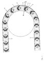
- FIG. 1 shows a top view of a transport chain 1 according to the invention this embodiment is only a transport chain 1, which is deflected in a U-shape, shown. Nevertheless, two or more can also be used in preferred arrangements Transport chains 1 run parallel to each other to also larger objects to be able to transport.
- the transport chain 1 consists of a variety of Main links 2, shown by connecting links 4, dashed, with each other are connected. The connection is designed so that the connecting links 4 are largely covered by the main links 2.
- the connection between the main links 2 and the connecting links 4 is by a first hinge 6 and designed to be movable by a second hinge 8, the pivot axes A, B of the two hinges 6, 8 essentially are formed perpendicular to each other.
- the pivot axis A of the hinge 6 extends essentially perpendicular to the chain longitudinal direction and parallel to Surface of the transport chain 1, so that a bending movement between the Chain links 2, 4 in the chain longitudinal direction perpendicular to the chain surface becomes possible.
- the pivot axis B of the hinge 8 extends essentially perpendicular to the surface of the transport chain 1 and enables one Swiveling movement of the chain in the conveyor plane.
- the main members 2 are configured on the top in the form of a cover plate 10, which the hinges 6, 8 and the connecting links 4 largely covered.
- the hinges 6, 8 are arranged protected, so that their large Mobility is also ensured in the long term.
- This top view shows that the transport chain 1 can also run through very tight curve radii, in particular the hinge 8 offers great freedom of movement, less thanks to the hinge 8 itself than is limited by the abutting parts of the main links 2.
- FIG. 2 shows a sectional side view of the transport chain according to the invention 1.
- the transport chain 1 is guided in a chain support profile 12 and deflected via a sprocket 14 and driven by this at the same time.
- the sprocket 14 can by a hub 20, which here has an essentially square cross section, mounted on a shaft to be driven over it.
- the transport chain is on the top of the support section 12 guided and then deflected over the sprocket 14.
- the return 24 of the transport chain 1 takes place parallel to the outflow 22 of the transport chain 1, below the Hinvieres 22 inside the chain support profile 12. Because the return 24th takes place inside the chain support profile 12, the transport chain 1 is protected from damage or pollution protected. Furthermore, the number of exposed, Moving parts are reduced, reducing the risk of injury to those in the area the transport chain 1 handling people is minimized. Furthermore is in figure 2 recognizable that the hinges 6 a movement of the main links 2 in two Allow directions to each other. Thus, the transport chain 1 through the Pivotal movement around the hinges 6 can be bent in two directions. First, the transport chain 1 is bent down over the chain wheel 14, to then after wrapping the sprocket 14 in the opposite Direction to be bent.
- the tops of the main limbs 2 are designed as cover plates 10 which are almost continuous Form the surface of the transport chain 1.
- the extremely narrow column 26 between the individual main links 2 at the top are advantageous formed obliquely so that the hinges 6, 8 of the cover plates 10 of the Main links 2 are almost completely covered.
- the narrow column 26 limit the freedom of movement of the hinges 6 in a vertical Direction, i.e.
- the bottom of the main limbs too 2 are in the form of cover plates 28, which are the engagement openings 16 for the teeth 18 of the sprocket 14 and larger gaps 30 between the have individual main links 2, the greater flexibility of the hinges 6 allow in a swivel direction downwards. It will achieves that a sprocket 14, which serves as a drive or deflection wheel with a smaller radius can be formed.
- the larger column 30 on the underside of the transport chain 1 are less annoying because they are protected in the Run inside the chain support profile 12 and thus the risk of intrusion of dirt is low.
- the connecting links 4 are essentially complete between the cover plates 10 and 28 on the top and bottom of the Main links 2. This allows in addition to dirt or mechanical Damage protected location a large support area between the main and Links, which ensures a high load capacity of the transport chain 1 is achieved.
- Figure 3 shows a main link 2 in different views.
- Figure 3 is on the right a plan view of the main part 2 is shown.
- the main part 2 becomes almost complete covered by the cover plate 10.
- This forms a large one Wing on which loads to be conveyed have a secure footing.
- the middle piece 32 of the main link shown here in dashed lines, is almost completely covered by the cover plate 10 and lies opposite the side edges of the Cover plate 10 is set back, whereby lateral guide grooves 34 are formed be in which the chain support profile 12 can engage.
- On the middle piece 32 the main part of the hinges 6 and 8 are formed.
- the hinge 6 consists of several comb-like There are projections 35, in the spaces between the corresponding, likewise comb-like counterparts of the link 4 can engage. So will high load-bearing capacity and even power transmission through the hinge 6 guaranteed.
- the hinge 8 is opposite the front edge 36 of the Main link 2 is set back inward, thereby allowing the assembled state of the transport chain 1 the intermediate link 4 almost is completely covered by the cover plate 10.
- the hinge 8th is designed like a comb, this hinge 8 also has a high load-bearing capacity and even application of force ensured.
- the lower cover plate 28 extends in the direction of the front edge 36 of the main member 2 over the Hinge 8 so that together with the upper cover plate 10 Recording space 37 is created for the intermediate member 4. Because of the comb-like Extend protrusions of the main link-side parts of the hinges 6 and 8 bores 38 and 40 are inserted into the hinge bolts 39, 41 can.
- the bore 40 of the hinge 8 is not continuous, but covered on its top by the cover plate 10, thereby a Prevents dirt from entering the hinge from the top of the chain becomes.
- the hinge bores 38 and 40 also have latching devices 42 and 44, in which the hinge bolts 39, 41 can be locked.
- 3 is a top view of the underside a main link 2 shown.
- the middle part 32 of the main link 2 is almost completely covered by the lower cover plate 28.
- the lower one Cover plate 28 projects, like the upper cover plate 10, laterally over the Middle part 32, which together with the upper cover plate 10 guide groove 34 described above is formed.
- the middle part 32 is located in the underside of the engagement opening 16 into which a Tooth 18 of a chain wheel 14 can engage.
- the lower cover plate 28 has in particular in the longitudinal direction a smaller extent than the upper cover plate 10, whereby when the transport chain 1 bends around the pivot axes A greater mobility is achieved downwards.
- FIG. 4 shows different views of the connecting element 4.
- the connecting element 4 has at its two longitudinal ends the link-side Parts of hinges 6 and 8. These parts are also comb-like, so that they are in the corresponding spaces between the parts on the main limb the hinges 6, 8 can engage. Extend through the two hinge parts hinge bores 48 and 50 through which the hinge bolts 39, 41, which extends through the hinge bores 38 and 40 on the main link 2 extending, in the assembled state of the hinge 6, 8 also extend.
- the middle part 46 of the connecting member 4 has cutouts, that only the material saving and thus a weight reduction serve.
- the two longitudinal ends of the connecting member 4 are corresponding to the Swing direction of hinges 6 and 8 rounded to a large one To allow freedom of movement.
- the connecting member advantageously has 4 on a smaller width than the central part 32 of the main member 2, whereby in the transport chain 1 it is ensured that the guide essentially through the smooth side edges of the middle part 32 of the main member 2 in the Guide grooves 34 takes place
- the cross section shown in Figure 5 shows a chain support profile 12 with the Transport chain according to the invention 1.
- the chain support profile leads on its upper side 12 the transport chain 1 in the forward direction 22.
- the transport chain 1 in is in a closed cavity 52 led their return 24.
- slide rails 56 are attached, which slide as easily as possible allow the transport chain 1 on the chain support profile 12.
- These slide rails 56 are advantageously made of plastic, the highly sliding properties owns, manufactured. This can be a polyamide, for example.
- Cavity 52 for the return 24 of the transport chain 1 are on the chain support profile 12 more projections 58 attached.
- These protrusions 58 bear like that Projections 54 on the top of the chain support profile 12 also slide rails 60.
- These slide rails 60 are advantageously identical to those Slide rails 56 used on the top of the chain support section 12 become. This enables a reduction in the number of parts required.
- the Projections 58 with the slide rail 60 also engage in the guide grooves 34 the main links 2 of the transport chain 1. However, the main links are 2 the transport chain 1 in its return 24 with the lower cover plates 28 the slide rails 60, while in the forward 22 the transport chain 1 through the upper cover plates 10 of the main links 2 is worn.
- the cover plate 10 protrudes beyond the projections 54 of the chain support profile 12, so that the chain support profile 12 is completed by the cover plate 10 upwards, whereby penetration of dirt into the interior of the chain support profile and in particular is prevented in the hinges of the transport chain 1.
- a guide rail is in the support profile 12 shown here 62 attached. This guide rail 62 is essentially at a right angle to the surface of the transport chain 1 and extends parallel to the chain longitudinal direction along the transport route.
- a sliding body 64 is used, the lateral guidance an object to be transported on the transport chain 1.
- the chain support profile 12 shown here is advantageously designed so that the Use of this chain support profile 12 not on the transport chain according to the invention 1 is limited, but rather also the use of a transport belt or a roller chain.
Description
Die Erfindung betrifft eine Transportkette zum Fördern von Gegenständen.The invention relates to a transport chain for conveying objects.
Es sind Transportketten bekannt, die in der Industrie zum Fördern von verschiedenartigen Gegenständen eingesetzt werden. Derartige Transportketten bestehen aus zahlreichen Kettengliedern, die in der Regel eine plane Oberfläche aufweisen, auf die die zu fördernden Gegenstände gestellt werden können. Häufig werden mindestens zwei parallel zueinander verlaufende Transportketten eingesetzt, um auch größere Gegenstände transportieren zu können, die dann auf beiden Ketten aufliegen. Die einzelnen Kettenglieder sind beweglich miteinander verbunden, um Schwenkbewegungen in zwei zueinander senkrechten Richtungen zu ermöglichen. Zum einen müssen die Kettenglieder sich in der Transportebene zueinander bewegen können, um auch einen Verlauf der Transportstrecke in Kurven zu ermöglichen, andererseits müssen sich die Kettenglieder senkrecht zu der Transportebene zueinander bewegen können, um einen Rücklauf der Kettenglieder unterhalb der Förderebene zu ermöglichen. Bei den bekannten Transportketten wird diese um zwei Achsen bewegliche Verbindung zwischen den Kettengliedern häufig durch eine Art Kreuzgelenk gebildet, d.h. die beiden Schwenkachsen schneiden sich in einen Punkt. Diese Gelenkverbindung ist so aufgebaut, daß die einzelnen Kettenglieder mittels horizontaler bzw. parallel zur Transportebene verlaufender Schwenkachsen, die eine Schwenkbewegung senkrecht zur Transportebene ermöglichen, miteinander verbunden sind. Diese Schwenkachsen sind jeweils in einem ersten Kettenglied festgelagert, während sie sich in dem angrenzenden zweiten Kettenglied durch Langlöcher erstrecken, die nicht nur eine Drehbewegung der beiden Kettenglieder zueinander um diese Achse ermöglichen, sondern der Achse eine zusätzliche Bewegungsfreiheit in Richtung der Transportebene geben, die eine Schwenkbewegung der Kettenglieder innerhalb der Transportebene ermöglicht. Es existiert also nur eine reale Schwenkachse, die Schwenkbewegung um die zweite, nicht real vorhandene, Schwenkachse wird lediglich durch ein Spiel der Lagerung der ersten Achse in einem der beiden aneinander angrenzenden Kettenglieder erreicht. Aufgrund dieser Konstruktion ergibt sich bei den bekannten Transportketten dieser Art nur eine eingeschränkte Beweglichkeit. Weiterhin kann sich in den seitlichen Langlöchern, durch die die Schwenkachsen geführt sind, leicht Schmutz ansammeln, der die Beweglichkeit und damit die Funktion der Transportkette weiter einschränkt. Die geringe Beweglichkeit derartiger Transportketten erfordert zusätzlich ein großes Spiel in der seitlichen Führung, um einen Verlauf in Kurven zu ermöglichen.Transport chains are known which are used in the industry for conveying various types Objects are used. Such transport chains consist of numerous chain links, which usually have a flat surface have on which the objects to be conveyed can be placed. Often there will be at least two transport chains running parallel to each other used to be able to transport larger objects, which then rest on both chains. The individual chain links are movable with each other connected to swivel movements in two mutually perpendicular Enable directions. First, the chain links must be in the Transport plane can move to each other, also a course of the transport route to allow in curves, on the other hand, the chain links can move perpendicular to the transport plane to each other to reverse to allow the chain links below the conveyor level. With the known Transport chains become this connection that can move around two axes often formed by a kind of universal joint between the chain links, i.e. the two Swivel axes intersect at one point. This articulation is so built up that the individual chain links by means of horizontal or parallel to Transport plane running swivel axes, the swivel movement enable perpendicular to the transport plane, are interconnected. This Swivel axes are each fixed in a first chain link, while they extend through elongated holes in the adjacent second chain link, which is not just a rotational movement of the two chain links with respect to one another Enable axis, but the axis an additional freedom of movement Direction of the transport plane give a pivoting movement of the chain links within the transport level. So there is only a real one Swivel axis, the swivel movement around the second, not really existing, Pivotal axis is just a game of storage of the first axis in reached one of the two adjacent chain links. by virtue of this construction results in only one of the known transport chains of this type restricted mobility. Furthermore, in the side elongated holes, through which the swivel axes are guided, easily collect dirt, which the Mobility and thus the function of the transport chain are further restricted. The low mobility of such transport chains additionally requires great play in the side guide to allow a course in curves.
GB 897,549 offenbart eine Transportkette, bei welcher eine Vielzahl von Hauptgliedern jeweils über Verbindungsglieder miteinander verbunden sind. Dabei weisen die Hauptglieder an ihren Oberseiten Tragplatten auf, welche sich seitlich über die Hauptglieder hinaus erstrecken, um Lasten zu tragen. Die Haupt- und Verbindungsglieder sind an Schwenkachsen miteinander verbunden, wobei sich die Schwenkachsen abwechselnd senkrecht zueinander erstrecken. Das heißt, ein Verbindungsglied ist an einem ersten Ende mit einem angrenzenden Hauptglied über eine waagerechte Schwenkachse verbunden und an dem entgegengesetzten Ende mit einem weiteren Hauptglied über eine vertikal verlaufende Schwenkachse verbunden. Die Haupt- und Verbindungsglieder, welche unterhalb der Tragplatten angeordnet sind, sind offen ausgebildet, d.h. die Schwenkachsen sind zur Seite und nach unten frei zugänglich, so daß sie leicht verschmutzen können.GB 897,549 discloses a transport chain in which a plurality of main links are connected to each other via connecting links. there have the main links on their tops support plates, which are laterally Extend beyond the main limbs to carry loads. The main and Connecting links are connected to one another on swivel axes, whereby the pivot axes alternately extend perpendicular to each other. This means, a link is at a first end with an adjacent main link connected via a horizontal swivel axis and on the opposite End with another main link over a vertical one Pivot axis connected. The main and connecting links, which are below of the support plates are open, i.e. the swivel axes are freely accessible to the side and downwards so that they easily become dirty can.
Es ist Aufgabe der Erfindung, eine verbesserte Transportkette zu schaffen, die unter Beibehaltung einer großen Beweglichkeit wenig anfällig für Verschmutzungen und Beschädigungen ist.It is an object of the invention to provide an improved transport chain while maintaining a large one Mobility less susceptible to contamination and is damage.
Diese Aufgabe wird durch die im Anspruch 1 angegebenen Merkmale gelöst.
Bevorzugte Ausführungsformen ergeben sich aus den Unteransprüchen.This object is achieved by the features specified in
Die erfindungsgemäße Transportkette weist für die zwei erforderlichen Schwenkbewegungen zwischen den einzelnen Kettengliedern zwei separate Scharniere auf, die über entsprechende Verbindungsglieder miteinander verbunden sind. Durch diese Entkopplung der beiden Schwenkachsen wird die große Bewegungsfreiheit der Kettenglieder um die jeweilige Achse ermöglicht. Weiterhin kann auf die äußerst schmutzempfindlichen, aus dem Stand der Technik bekannten seitlichen Langlöcher verzichtet werden, wodurch die Zuverlässigkeit der Funktion der Transportkette erhöht wird. Bei der erfindungsgemäßen Transportkette wird die Beweglichkeit der Kettenglieder zueinander nicht durch die Konstruktion der Gelenke selber begrenzt, sondern lediglich durch eventuelle Anschläge, die sich aus der Gestalt der Ober- und Unterseiten der Hauptglieder ergeben. Die Verbindungsglieder werden an ihren Ober- und Unterseiten jeweils von dem an das zweite Scharnier angrenzenden Hauptglied bis in den Bereich des ersten Scharniers vollständig überdeckt. Dies hat den Vorteil, daß sich auf der Kettenoberseite eine nahezu durchgängige, glatte Oberfläche bildet, die nur durch einen schmalen Spalt zwischen den einzelnen Hauptgliedern unterbrochen wird. Dies ermöglicht eine große Standfläche für die zu transportierenden Güter und die Scharniere zwischen den einzelnen Kettengliedern werden durch die Abdeckung vor Schmutzeinwirkung oder mechanischen Beschädigungen geschützt. Die Abdeckung der Verbindungsglieder an ihrer Unterseite ermöglicht eine nahezu durchgängige, glatte Auflagefläche der Transportkette, die die Gleiteigenschaften der Kette in einer Führung verbessern. Trotz der nahezu vollständigen Abdeckung des Verbindungsgliedes wird die Beweglichkeit der beiden Hauptglieder parallel zur Kettenoberfläche kaum eingeschränkt. Auch die Beweglichkeit zwischen den Hauptgliedern senkrecht zur Kettenoberfläche bzw. zur Transportebene wird kaum eingeschränkt, da die Trennfuge zwischen den Ober- und Unterseiten der beiden aneinandergrenzenden Hauptglieder im Bereich des zweiten Scharniers liegt. Dadurch werden die beiden Scharniere optimal geschützt, ohne die Beweglichkeit der Transportkette bedeutend einzuschränken.The transport chain according to the invention points for the two required pivoting movements two separate hinges between the individual chain links on, which are connected to one another via corresponding connecting links. This decoupling of the two swivel axes provides great freedom of movement the chain links around the respective axis. Farther can on the extremely dirt-sensitive, known from the prior art side slots are dispensed with, which increases the reliability of the Function of the transport chain is increased. In the transport chain according to the invention the mobility of the chain links to each other will not through the construction of the joints themselves limited, but only by any attacks that arise from the shape the top and bottom sides of the main limbs. The links are on the top and bottom sides of the second hinge adjacent main link up to the area of the first hinge completely covered. This has the advantage that there is almost an upper side of the chain continuous, smooth surface that forms only through a narrow gap between the individual main links. This enables one large footprint for the goods to be transported and the hinges between the individual chain links are covered with dirt or mechanical damage. The cover of the Connecting links on their underside enables an almost continuous, smooth contact surface of the transport chain, which reflects the sliding properties of the chain improve a leadership. Despite the almost complete cover of the connecting link the mobility of the two main links is parallel to the chain surface hardly restricted. The mobility between the main limbs perpendicular to the chain surface or to the transport plane is hardly limited because the parting line between the top and bottom of the two adjacent main links is in the area of the second hinge. This provides optimal protection for the two hinges without mobility significantly restrict the transport chain.
Sämtliche Hauptglieder und sämtliche Verbindungsglieder sind vorzugsweise jeweils identisch ausgebildet. Dies ermöglicht einen kostengünstigen Aufbau der Transportkette, da diese nur aus zwei unterschiedlichen Bauteilen, den Hauptund den Verbindungsgliedern besteht.All main links and all connecting links are preferred each formed identically. This enables an inexpensive construction of the Transport chain, since this only consists of two different components, the main and the links exist.
Bevorzugt weisen die Hauptglieder auf ihren Unterseiten Ausnehmungen auf, in die ein Kettenrad eingreifen kann. Diese Ausnehmungen auf der Unterseite können unabhängig von der übrigen Gestalt des Kettengliedes so ausgebildet werden, daß ein besonders günstiger Kontakt zwischen dem Kettenrad und den Hauptgliedern ermöglicht wird. Dadurch wird ein zuverlässiger und sicherer Antrieb der Transportkette ermöglicht, über den auch große Kräfte zuverlässig übertragen werden können, so daß auch schwerere Güter auf der Transportkette transportiert werden können.The main members preferably have recesses on their undersides, in that a sprocket can engage. These recesses on the bottom can be designed regardless of the rest of the shape of the chain link be that a particularly favorable contact between the sprocket and the Main links is made possible. This will make it more reliable and safer Drive of the transport chain enables reliable, even large forces can be transferred so that even heavier goods on the transport chain can be transported.
Weiter bevorzugt weisen die Hauptglieder seitliche, in Kettenlängsrichtung verlaufende Führungsnuten auf. Diese Führungsnuten erlauben eine sichere Führung der Transportkette in einem entsprechenden Führungsprofil. Günstigerweise sind die Führungsnuten so ausgestaltet, daß die Oberseite des Führungsprofils durch die oberen Flanken der Führungsnut, insbesondere auch in Kurven, überdeckt wird. Dadurch wird verhindert, daß sich Schmutz oder auch Teile der zu fördernden Güter zwischen der Transportkette und dem Führungsprofil festsetzen bzw. verfangen können. Die Transportkette bildet somit gemeinsam mit dem Führungsprofil eine glatte, nahezu geschlossene Oberfläche, die das Eindringen von Fremdkörpern in die Führungsbahn und damit eine eventuelle Funktionsstörung verhindert. Weiterhin kann durch die Ausbildung einer solchen Führungsnut erreicht werden, daß die Hauptglieder sowohl mit der oberen Flanke der Führungsnut als auch mit ihrer Unterseite auf dem Führungsprofil aufliegen, wodurch eine erhöhte Tragfähigkeit erzielt werden kann.The main links further preferably have lateral ones running in the chain longitudinal direction Guide grooves. These guide grooves allow safe guidance the transport chain in a corresponding management profile. Are favorably the guide grooves designed so that the top of the guide profile through the upper flanks of the guide groove, especially in curves, covered becomes. This prevents dirt or parts of the material to be conveyed Fix goods between the transport chain and the management profile or can get caught. The transport chain thus forms together with the guide profile a smooth, almost closed surface that prevents the ingress of Foreign bodies in the guideway and thus a possible malfunction prevented. Furthermore, by forming such a guide groove be achieved that the main links with both the upper flank of the guide groove as well as rest with their underside on the guide profile, whereby an increased load-bearing capacity can be achieved.
Vorzugsweise besteht zumindest eines der beiden Scharniere aus mehreren kammartigen Vorsprüngen am Hauptglied und entsprechenden kammartigen Vorsprüngen am Verbindungsglied, die in die Zwischenräume der Vorsprünge am Hauptglied eingreifen, wobei ein durchgehender Scharnierbolzen sich durch die Vorsprünge des Haupt- und des Verbindungsgliedes erstreckt. Diese Ausgestaltung der Scharniere gewährleistet, daß der Scharnierbolzen sowohl an dem Verbindungsglied als auch an dem Hauptglied mehrfach gelagert ist, wodurch die zuverlässige Übertragung auch größerer Kräfte sichergestellt wird. Weiterhin ist die Kraftübertragung durch die mehrfache Lagerung des Scharnierbolzens auch äußerst gleichmäßig.At least one of the two hinges preferably consists of several comb-like projections on the main link and corresponding comb-like Projections on the connecting link, which in the spaces between the projections on Main link engage, with a continuous hinge pin through the Projections of the main and the connecting member extends. This configuration the hinge ensures that the hinge pin on both the Link as well as on the main link is mounted several times, whereby the reliable transmission of larger forces is ensured. Still is the power transmission through the multiple storage of the hinge pin extremely even.
Die Scharnierbolzen werden vorzugsweise durch Rastverbindungen in den Scharnieren gehalten. Dies ermöglicht eine einfache Montage der Transportkette, da die Scharnierbolzen lediglich in die entsprechenden Öffnungen der Scharniere eingesteckt werden müssen und in diesen sicher verrasten. Es sind somit keine weiteren Befestigungselemente und Befestigungsvorgänge erforderlich.The hinge bolts are preferably by locking connections in the Hinges held. This enables easy assembly of the transport chain, because the hinge pins only in the corresponding openings of the hinges must be plugged in and securely locked in place. So there are none further fasteners and fastening processes required.
Weiter bevorzugt besteht der Scharnierbolzen aus Kunststoff. Somit ist eine Korrosion des Scharnierbolzens ausgeschlossen, welche die Beweglichkeit des Scharniers einschränken würde. Weiterhin ist ein Scharnierbolzen, insbesondere ein Scharnierbolzen, der Rastverbindungen aufweist, aus Kunststoff äußerst kostengünstig und leicht zu fertigen.The hinge pin is further preferably made of plastic. So is one Corrosion of the hinge pin excluded, which affects the mobility of the Would limit the hinge. Furthermore, a hinge pin, in particular a hinge pin, which has snap connections, extremely plastic inexpensive and easy to manufacture.
Bevorzugterweise sind die Hauptglieder und die Verbindungsglieder jeweils einstückig, vorzugsweise aus Kunststoff ausgebildet. Die einstückige Ausgestaltung der einzelnen Glieder reduziert die Anzahl der notwendigen Montagetätigkeiten und erlaubt somit eine schnellere und kostengünstigere Montage der Transportkette. Weiterhin wird durch die reduzierte Teileanzahl die Zahl möglicher Fehler verringert und dadurch die Zuverlässigkeit der Transportkette gesteigert. Die Haupt- und Verbindungsglieder sind aus Kunststoff besonders leicht und kostengünstig zu fertigen und zusätzlich wird durch den Einsatz von Kunststoff eine mögliche, die Funktion beeinträchtigende Korrosion der Transportkette ausgeschlossen.The main links and the connecting links are preferably each in one piece, preferably made of plastic. The one-piece design of the individual links reduces the number of necessary Assembly activities and thus allows faster and cheaper Assembly of the transport chain. Furthermore, due to the reduced number of parts Reduced the number of possible errors and thereby the reliability of the transport chain increased. The main and connecting links are made of plastic particularly easy and inexpensive to manufacture and is also by the Use of plastic is a possible corrosion that impairs functionality excluded from the transport chain.
Die Erfindung wird nachfolgend beispielhaft unter Bezugnahme auf die beiliegenden
Zeichnungen beschrieben. In den Zeichnungen zeigen:
Figur 1 zeigt eine Draufsicht auf eine erfindungsgemäße Transportkette 1. In
dieser Ausführung ist nur eine Transportkette 1, die U-förmig umgelenkt wird,
gezeigt. Dennoch können in bevorzugten Anordnungen auch zwei oder mehr
Transportketten 1 parallel zueinander laufen, um auch größere Gegenstände
transportieren zu können. Die Transportkette 1 besteht aus einer Vielzahl von
Hauptgliedern 2, die durch Verbindungsglieder 4, gestrichelt dargestellt, miteinander
verbunden sind. Die Verbindung ist so gestaltet, daß die Verbindungsglieder
4 weitgehend von den Hauptgliedern 2 überdeckt werden. Die Verbindung
zwischen den Hauptgliedern 2 und den Verbindungsgliedern 4 ist durch ein
erstes Scharnier 6 und durch ein zweites Scharnier 8 beweglich ausgestaltet,
wobei die Schwenkachsen A, B der beiden Scharniere 6, 8 im wesentlichen
senkrecht zueinander ausgebildet sind. Die Schwenkachse A des Scharniers 6
erstreckt sich im wesentlichen senkrecht zur Kettenlängsrichtung und parallel zur
Oberfläche der Transportkette 1, so daß eine Biegebewegung zwischen den
Kettengliedern 2, 4 in Kettenlängsrichtung senkrecht zur Kettenoberfläche
möglich wird. Die Schwenkachse B des Scharniers 8 erstreckt sich im wesentlichen
senkrecht zur Oberfläche der Transportkette 1 und ermöglicht eine
Schwenkbewegung der Kette in der Förderebene.FIG. 1 shows a top view of a
Die Hauptglieder 2 sind an ihrer Oberseite in Form einer Abdeckplatte 10 ausgestaltet,
welche die Scharniere 6, 8 und die Verbindungsglieder 4 weitgehend
überdeckt. Hierdurch ergibt sich eine nahezu durchgängige, glatte Oberfläche der
Transportkette 1, die wenig Spalte aufweist, in die Schmutz eindrigen kann.
Dadurch sind die Scharniere 6, 8 geschützt angeordnet, so daß ihre große
Beweglichkeit auch langfristig sichergestellt ist. Weiterhin ist in Figur 1 noch das
Kettentragprofil 12 angedeutet, welches die Transportkette 1 trägt und führt. In
dieser Draufsicht ist zu erkennen, daß die erfindungsgemäße Transportkette 1
auch sehr enge Kurvenradien durchlaufen kann, insbesondere das Scharnier 8
bietet eine große Bewegungsfreiheit, die weniger durch das Scharnier 8 selber
als durch das Aneinanderstoßen von Teilen der Hauptglieder 2 begrenzt wird.The
Figur 2 zeigt eine geschnittene Seitenansicht der erfindungsgemäßen Transportkette
1. Hier ist insbesondere die Führung und der Antrieb der Transportkette
1 gezeigt. Die Transportkette 1 wird in einem Kettentragprofil 12 geführt und
über ein Kettenrad 14 umgelenkt und von diesem gleichzeitig angetrieben. Hierzu
weisen die Hauptglieder 2 an ihrer Unterseite Ausnehmungen 16 auf, in die
Zähne 18 des Kettenrades 14 eingreifen können. Das Kettenrad 14 kann mittels
einer Nabe 20, die hier einen im wesentlichen quadratischen Querschnitt aufweist,
auf einer Welle befestigt werden, um über diese angetrieben zu werden.
Im Hinlauf 22 wird die Transportkette an der Oberseite des Tragprofils 12
geführt und dann über das Kettenrad 14 umgelenkt. Der Rücklauf 24 der Transportkette
1 erfolgt parallel zu dem Hinlauf 22 der Transportkette 1, unterhalb des
Hinlaufes 22 im Inneren des Kettentragprofils 12. Dadurch, daß der Rücklauf 24
im Inneren des Kettentragprofils 12 erfolgt, ist die Transportkette 1 vor Beschädigung
oder Verschmutzung geschützt. Ferner wird die Anzahl der freiliegenden,
bewegten Teile reduziert, wodurch die Verletzungsgefahr für in der Umgebung
der Transportkette 1 hantierende Personen minimiert wird. Weiterhin ist in Figur
2 erkennbar, daß die Scharniere 6 eine Bewegung der Hauptglieder 2 in zwei
Richtungen zueinander ermöglichen. Somit kann die Transportkette 1 durch die
Schwenkbewegung um die Scharniere 6 in zwei Richtungen gebogen werden.
Zunächst wird die Transportkette 1 über das Kettenrad 14 nach unten umgebogen,
um dann nach Umschlingung des Kettenrades 14 in die entgegengesetzte
Richtung gebogen zu werden. Dies ermöglicht, daß trotz eines großen Kettenrades
14, welches eine günstige Kraftübertragung ermöglicht, der Hinlauf 22 und
der Rücklauf 24 der Transportkette 1 in einem gemeinsamen Kettentragprofil 12,
äußerst eng beieinander erfolgen können. Somit wird eine äußerst kompakte und
platzsparende Anordnung der Transportkette 1 erzielt. Die Oberseiten der Hauptglieder
2 sind als Abdeckplatten 10 ausgebildet, die eine nahezu durchgehende
Oberfläche der Transportkette 1 bilden. Die äußerst schmalen Spalte 26 zwischen
den einzelnen Hauptgliedern 2 an deren Oberseite sind vorteilhafterweise
schräg ausgebildet, so daß die Scharniere 6, 8 von den Abdeckplatten 10 der
Hauptglieder 2 nahezu vollständig überdeckt werden. Die schmalen Spalte 26
begrenzen zwar den Bewegungsfreiraum der Scharniere 6 in einer vertikalen
Richtung, d.h. in Richtung senkrecht zur Transportebene, doch ist in dieser
vertikalen Schwenkrichtung nur eine geringe Bewegungsfreiheit erforderlich, da
diese Beweglichkeit nur für den Rücklauf 24, bei dem, wie gezeigt, ein großer
Krümmungsradius möglich ist, benötigt wird. Weiterhin ist eine geringe Bewegungsfreiheit
in dieser Richtung erforderlich für den Fall, in welchem die Transportkette
1 Steigungen überwinden soll. Auch die Unterseiten der Hauptglieder
2 sind in Form von Abdeckplatten 28 ausgebildet, welche die Eingriffsöffnungen
16 für die Zähne 18 des Kettenrades 14 sowie größere Spalte 30 zwischen den
einzelnen Hauptgliedern 2 aufweisen, die eine größere Beweglichkeit der Scharniere
6 in einer Schwenkrichtung nach unten ermöglichen. Dadurch wird es
erreicht, daß ein Kettenrad 14, das als Antriebs- oder Umlenkrad dient, mit
einem geringeren Radius ausgebildet werden kann. Die größeren Spalte 30 an
der Unterseite der Transportkette 1 sind weniger störend, da sie geschützt im
Inneren des Kettentragprofils 12 verlaufen und somit die Gefahr des Eindringens
von Schmutz gering ist. Die Verbindungsglieder 4 liegen im wesentlichen vollständig
zwischen den Abdeckplatten 10 und 28 an der Ober- und Unterseite der
Hauptglieder 2. Dies ermöglicht neben der vor Schmutz oder mechanischer
Beschädigung geschützten Lage eine große Abstützfläche zwischen den Hauptund
Verbindungsgliedern, wodurch eine hohe Tragfähigkeit der Transportkette 1
erzielt wird.Figure 2 shows a sectional side view of the transport chain according to the
Figur 3 zeigt ein Hauptglied 2 in verschiedenen Ansichten. In Figur 3 rechts ist
eine Draufsicht auf das Hauptteil 2 dargestellt. Das Hauptteil 2 wird fast vollständig
von der Abdeckplatte 10 überdeckt. Diese bildet somit eine große
Tragfläche, auf der zu fördernde Lasten einen sicheren Stand haben. Das Mittelstück
32 des Hauptgliedes 2, hier gestrichelt dargestellt, wird nahezu vollständig
von der Abdeckplatte 10 überdeckt und liegt gegenüber den Seitenkanten der
Abdeckplatte 10 zurückversetzt, wodurch seitliche Führungsnuten 34 gebildet
werden, in die das Kettentragprofil 12 eingreifen kann. An dem Mittelstück 32
sind die hauptgliedseitigen Teile der Scharniere 6 und 8 ausgebildet. In der
Draufsicht ist zu erkennen, daß das Scharnier 6 aus mehreren kammartigen
Vorsprüngen 35 besteht, in deren Zwischenräume die entsprechenden, ebenfalls
kammartigen Gegenstücke des Verbindungsgliedes 4 eingreifen können. So wird
eine hohe Tragfähigkeit und gleichmäßige Kraftübertragung durch das Scharnier
6 gewährleistet. Das Scharnier 8 ist gegenüber der vorderen Kante 36 des
Hauptgliedes 2 nach innen zurückversetzt, wodurch ermöglicht wird, daß im
zusammengebauten Zustand der Transportkette 1 das Zwischenglied 4 fast
vollständig von der Abdeckplatte 10 überdeckt wird. In der geschnittenen
Seitenansicht des Hauptgliedes 2 ist zu erkennen, daß auch das Scharnier 8
kammartig ausgebildet ist, so ist auch bei diesem Scharnier 8 eine hohe Tragfähigkeit
und gleichmäßige Krafteinleitung sichergestellt. Die untere Abdeckplatte
28 erstreckt sich in Richtung der vorderen Kante 36 des Hauptgliedes 2 über das
Scharnier 8 hinaus, so daß gemeinsam mit der oberen Abdeckplatte 10 ein
Aufnahmeraum 37 für das Zwischenglied 4 geschaffen wird. Durch die kammartigen
Vorsprünge der hauptgliedseitigen Teile der Scharniere 6 und 8 erstrekken
sich Bohrungen 38 und 40, in die Scharnierbolzen 39, 41 eingesetzt werden
können. Die Bohrung 40 des Scharniers 8 ist nicht durchgehend ausgebildet,
sondern an ihrer Oberseite durch die Abdeckplatte 10 überdeckt, wodurch ein
Eindringen von Schmutz von der Kettenoberseite in das Scharnier verhindert
wird. Die Scharnierbohrungen 38 und 40 weisen weiterhin Rasteinrichtungen 42
und 44 auf, in denen die Scharnierbolzen 39, 41 eingerastet werden können.
Dies ermöglicht eine einfache Montage, da jegliche Verschraubung der Scharniere
6, 8 entfällt und die Scharniere 6, 8 durch einfaches Zusammenstecken
montiert werden können. Links in Figur 3 ist eine Draufsicht auf die Unterseite
eines Hauptgliedes 2 dargestellt. Der Mittelteil 32 des Hauptgliedes 2 wird
nahezu vollständig von der unteren Abdeckplatte 28 überdeckt. Die untere
Abdeckplatte 28 ragt, ebenso wie die obere Abdeckplatte 10, seitlich über das
Mittelteil 32 hinaus, wodurch gemeinsam mit der oberen Abdeckplatte 10 die
zuvor beschriebene Führungsnut 34 gebildet wird. In etwa in der Mitte des
Mittelteils 32 befindet sich in der Unterseite die Eingriffsöffnung 16, in die ein
Zahn 18 eines Kettenrades 14 eingreifen kann. Die untere Abdeckplatte 28 hat
insbesondere in Längsrichtung eine geringere Ausdehnung als die obere Abdeckplatte
10, wodurch bei Biegung der Transportkette 1 um die Schwenkachsen A
nach unten eine größere Beweglichkeit erzielt wird.Figure 3 shows a
Figur 4 zeigt verschiedene Ansichten des Verbindungsgliedes 4. Das Verbindungsglied
4 weist an seinen beiden Längsenden die verbindungsgliedseitigen
Teile der Scharniere 6 und 8 auf. Auch diese Teile sind kammartig ausgebildet,
so daß sie in die korrespondierenden Zwischenräume der hauptgliedseitigen Teile
der Scharniere 6, 8 eingreifen können. Durch die beiden Scharnierteile erstrecken
sich Scharnierbohrungen 48 und 50, durch welche sich die Scharnierbolzen 39,
41, welche sich durch die Scharnierbohrungen 38 und 40 am Hauptglied 2
erstreckenden, im zusammengebauten Zustand des Scharniers 6, 8 ebenfalls
erstrecken. Das Mittelteil 46 des Verbindungsgliedes 4 weist Aussparungen auf,
die lediglich der Materialersparnis und damit auch einer Gewichtsreduzierung
dienen. Die beiden Längsenden des Verbindungsgliedes 4 sind entsprechend der
Schwenkrichtung der Scharniere 6 und 8 abgerundet, um eine große
Bewegungsfreiheit zu ermöglichen. Vorteilhafterweise weist das Verbindungsglied
4 eine geringere Breite als das Mittelteil 32 des Hauptgliedes 2 auf, wodurch
bei der Transportkette 1 sichergestellt ist, daß die Führung im wesentlichen
durch die glatten Seitenkanten des Mittelteils 32 des Hauptgliedes 2 in den
Führungsnuten 34 erfolgt.FIG. 4 shows different views of the connecting
Der in Figur 5 dargestellte Querschnitt zeigt ein Kettentragprofil 12 mit der
erfindungsgemäßen Transportkette 1. An seiner Oberseite führt das Kettentragprofil
12 die Transportkette 1 im Hinlauf 22. Im unteren Bereich des Kettentragprofils
12 wird in einem geschlossenen Hohlraum 52 die Transportkette 1 in
ihrem Rücklauf 24 geführt. Bei der Führung des Hinlaufs 22 der Transportkette
1 greift das Kettentragprofil 12 mit entsprechenden Vorsprüngen 54 in die
Führungsnuten 34 der Hauptglieder 2 der Transportkette 1 ein. Auf den Vorsprüngen
24 sind Gleitschienen 56 angebracht, die ein möglichst leichtes Gleiten
der Transportkette 1 auf dem Kettentragprofil 12 ermöglichen. Diese Gleitschienen
56 sind vorteilhafterweise aus Kunststoff, der hochgleitende Eigenschaften
besitzt, hergestellt. Dies kann beispielsweise ein Polyamid sein. In dem
Hohlraum 52 für den Rücklauf 24 der Transportkette 1 sind an dem Kettentragprofil
12 weitere Vorsprünge 58 angebracht. Diese Vorsprünge 58 tragen wie die
Vorsprünge 54 an der Oberseite des Kettentragprofils 12 ebenfalls Gleitschienen
60. Diese Gleitschienen 60 sind vorteilhafterweise identisch ausgebildet wie die
Gleitschienen 56, die an der Oberseite des Kettentragprofils 12 verwendet
werden. Dies ermöglicht eine Reduzierung der erforderlichen Teilevielfalt. Die
Vorsprünge 58 mit der Gleitschiene 60 greifen ebenfalls in die Führungsnuten 34
der Hauptglieder 2 der Transportkette 1 ein. Allerdings liegen die Hauptglieder 2
der Transportkette 1 in ihrem Rücklauf 24 mit den unteren Abdeckplatten 28 auf
den Gleitschienen 60 auf, während im Hinlauf 22 die Transportkette 1 durch die
obere Abdeckplatten 10 der Hauptglieder 2 getragen wird. Die Abdeckplatte 10
ragt über die Vorsprünge 54 des Kettentragprofils 12 hinaus, so daß das Kettentragprofil
12 durch die Abdeckplatte 10 nach oben abgeschlossen ist, wodurch
ein Eindringen von Schmutz in das Innere des Kettentragprofils und insbesondere
in die Scharniere der Transportkette 1 verhindert wird. Bevorzugterweise erstrecken
sich die Abdeckplatten 10 über die Vorsprünge 54 derart weit hinaus,
daß auch in einer Kurve eine vollständige Abdeckung des sich bildenden Spalts
gewährleistet ist. Zusätzlich ist bei dem hier gezeigten Tragprofil 12 eine Führungsschiene
62 angebracht. Diese Führungsschiene 62 steht im wesentlichen
in einem rechten Winkel zu der Oberfläche der Transportkette 1 und erstreckt
sich parallel zur Kettenlängsrichtung entlang des Transportweges. In dieses
Führungsglied 62 ist ein Gleitkörper 64 eingesetzt, der eine seitliche Führung
eines auf der Transportkette 1 zu transportierenden Gegenstandes sicherstellt.The cross section shown in Figure 5 shows a
Das hier gezeigte Kettentragprofil 12 ist vorteilhafterweise so gestaltet, daß die
Verwendung dieses Kettentragprofiles 12 nicht auf die erfindungsgemäße Transportkette
1 beschränkt ist, sondern vielmehr auch den Einsatz eines Transportriemens
oder einer Rollenkette ermöglicht.The
Claims (8)
- Transporting chain (1) with a multiplicity of main links (2) which are designed, on their top sides, as load-bearing surfaces, on which the loads which are to be conveyed are borne, and of which in each case two are connected to one another in a moveable manner via a connecting link (4) formed in one piece, it being the case that
a first end of a first main link (2) in the longitudinal direction of the chain, together with a first end of a connecting link (4), forms a first hinge (6), which allows a pivoting movement about an axis (A) essentially at right angles to the longitudinal direction of the chain and essentially parallel to the surface of the chain,
the second end of the connecting link (4), together with the second end of the following main link (2), forms a second hinge (8), which allows a pivoting movement about an axis (B) perpendicular to the longitudinal direction of the chain and to the pivoting axis (A) of the first hinge (6), and
the two axes (A, B), as seen in the longitudinal direction of the chain, are arranged in two different planes,
characterized in that
the main links (2) are each formed in one piece, and the connecting links (4) are each covered over completely on their top side and underside, into the region of the first hinge (6), in each case by the main link (2) adjacent to the second hinge (8). - Transporting chain (1) according to Claim 1, in the case of which all the main links (2) and all the connecting links (4) are of identical design in each case.
- Transporting chain (1) according to one of the preceding claims, in the case of which the main links (2), on their undersides, have cutouts (16) in which a chain wheel (14) can engage.
- Transporting chain (1) according to one of the preceding claims, in the case of which the main links (2) have lateral guide grooves (34) running in the longitudinal direction of the chain.
- Transporting chain (1) according to one of the preceding claims, in the case of which at least one of the two hinges (6, 8) comprises a plurality of comb-like protrusions on the main link (2) and corresponding comb-like protrusions on the connecting link (4), the latter protrusions engaging in the interspaces between the protrusions on the main link (2), a continuous hinge pin extending through the protrusions of the main link (2) and of the connecting link (4).
- Transporting chain (1) according to Claim 5, in the case of which the hinge pins (39, 41) are retained in the hinges (6, 8) by latching connections (42, 44).
- Transporting chain (1) according to Claim 5 or 6, in the case of which the hinge pins (39, 41) consist of plastic.
- Transporting chain (1) according to one of the preceding claims, in the case of which the main links (2) and the connecting links (4) are each formed in one piece, preferably from plastic.
Applications Claiming Priority (3)
| Application Number | Priority Date | Filing Date | Title |
|---|---|---|---|
| DE19817125A DE19817125A1 (en) | 1998-04-17 | 1998-04-17 | Chain conveyor with main links joined by connecting links |
| DE19817125 | 1998-04-17 | ||
| PCT/EP1999/002357 WO1999054239A1 (en) | 1998-04-17 | 1999-04-07 | Conveyor chain |
Publications (2)
| Publication Number | Publication Date |
|---|---|
| EP1084070A1 EP1084070A1 (en) | 2001-03-21 |
| EP1084070B1 true EP1084070B1 (en) | 2002-09-11 |
Family
ID=7864882
Family Applications (1)
| Application Number | Title | Priority Date | Filing Date |
|---|---|---|---|
| EP99919206A Expired - Lifetime EP1084070B1 (en) | 1998-04-17 | 1999-04-07 | Conveyor chain |
Country Status (5)
| Country | Link |
|---|---|
| US (1) | US6634491B1 (en) |
| EP (1) | EP1084070B1 (en) |
| JP (1) | JP2002512163A (en) |
| DE (2) | DE19817125A1 (en) |
| WO (1) | WO1999054239A1 (en) |
Families Citing this family (10)
| Publication number | Priority date | Publication date | Assignee | Title |
|---|---|---|---|---|
| US6428436B1 (en) * | 1999-04-27 | 2002-08-06 | Rexnord Corporation | Drive sprocket with relief areas |
| DE10118564A1 (en) * | 2001-04-14 | 2002-10-17 | Bosch Gmbh Robert | Continuous conveyor to promote a good |
| NL1020342C2 (en) * | 2002-04-09 | 2003-10-13 | Leonardus Antonius Julio Maria | Transport device. |
| DE10355872A1 (en) * | 2003-11-25 | 2005-06-30 | Hauni Maschinenbau Ag | Chain link for a conveyor chain of a machine of the tobacco processing industry |
| DE102006007838A1 (en) * | 2006-02-17 | 2007-08-30 | Comsort Gmbh | Tilting tray conveyor, has number of displaceable carriages along continuous tracks, tilted trays are provided for admission and for delivering goods at given positions |
| US7794330B2 (en) * | 2007-11-13 | 2010-09-14 | Gordon Jonathan I | Amusement apparatus |
| US8689968B2 (en) | 2009-02-03 | 2014-04-08 | Eckhard Polman | Conveyor device, conveyor chain as well as chain link |
| ES2495265B1 (en) * | 2013-03-15 | 2015-09-15 | Elisa ARGILÉS MAJÀ | FRUIT OR VEGETABLE TRANSPORTATION SYSTEM FOR A COLLECTION MACHINE AND COLLECTION MACHINE THAT INCLUDES SUCH SYSTEM |
| DE202017105927U1 (en) | 2017-09-28 | 2019-01-08 | Igus Gmbh | guide means |
| DE102018005568A1 (en) * | 2018-07-13 | 2020-01-16 | Mühlbauer Gmbh & Co. Kg | Device and method for producing RFID transponders with a sliding surface |
Family Cites Families (23)
| Publication number | Priority date | Publication date | Assignee | Title |
|---|---|---|---|---|
| US1424850A (en) * | 1921-04-02 | 1922-08-08 | Earnest Lawyer | Universal carrier chain |
| US1817373A (en) * | 1927-10-31 | 1931-08-04 | Hopkins Edmund Charles | Conveyer |
| DE1000742B (en) * | 1954-09-23 | 1957-01-10 | Alfred Scharf | Chain for chain conveyor |
| GB897549A (en) * | 1959-09-10 | 1962-05-30 | Supreme Conveyor Belt Company | Improvements relating to endless articulated slat conveyers |
| DE1207871B (en) * | 1962-08-13 | 1965-12-23 | Georg Willy A G | Transport device for dry brick |
| FR1368646A (en) * | 1963-09-11 | 1964-07-31 | Atlas Chain & Mfg Co | Improvements to roller chains and their links |
| US3317030A (en) * | 1965-03-23 | 1967-05-02 | Alpeda Ind Inc | Articulated-section conveyor structure |
| DE1802401B2 (en) * | 1968-01-31 | 1971-09-09 | JOINT CHAIN FOR CONVEYOR SYSTEMS WITH SUCCESSIVE U-SHAPED CHAINS TURNED 90 DEGREE | |
| FR2074612B1 (en) * | 1970-01-09 | 1974-10-31 | Stiegler Camille | |
| US3646752A (en) * | 1970-09-28 | 1972-03-07 | Conveyor Specialties Co | Plastic encased metal ribbed flexible conveyor chain |
| DE2431266A1 (en) * | 1974-06-28 | 1976-01-08 | Interroll Foerdertechnik Gmbh | Chain conveyor composed of plastic links - lightweight link design allows rapid assembly and dismantling |
| AT336491B (en) * | 1973-08-04 | 1977-05-10 | Interroll Foerdertechnik Gmbh | DETACHABLE JOINT CHAIN |
| US4153152A (en) | 1977-02-14 | 1979-05-08 | The Laitram Corporation | Bi-directional hinged conveyor belt |
| DE2822196A1 (en) * | 1978-05-20 | 1979-11-22 | Band Egon | Universally joined conveyor chain - passes round curves in two planes about its lengthwise axis |
| US4459124A (en) | 1980-10-31 | 1984-07-10 | Newton Alan R | Drive chain |
| SE455861B (en) * | 1981-09-30 | 1988-08-15 | Skf Ab | DEVICE BY A CHAIN TRANSPORT |
| IT1140085B (en) * | 1981-11-10 | 1986-09-24 | Regina Ind Srl | CONVEYOR TYPE CONVEYOR CHAIN |
| DE3321018A1 (en) | 1983-06-10 | 1984-12-13 | Otmar Fahrion | CHAIN CONVEYOR UNIT |
| US4961492A (en) * | 1988-07-22 | 1990-10-09 | Simplimatic Engineering Company | Article carrying conveyor and wearstrip set therefor |
| IT228635Y1 (en) * | 1992-05-07 | 1998-05-07 | Marbett Spa | CHAIN FOR THE REALIZATION OF TRANSPORT |
| DE4324120A1 (en) | 1993-07-19 | 1995-01-26 | Hauni Werke Koerber & Co Kg | Conveyor chain |
| DK9400401U3 (en) * | 1994-10-25 | 1995-03-10 | Maskinfabrikken Baeltix A S En | Chain link for conveyor chain |
| IT234202Y1 (en) * | 1994-11-08 | 2000-02-23 | Regina Sud Spa | CHAIN CONVEYOR WITH IMPROVED SLIDING FEATURES |
-
1998
- 1998-04-17 DE DE19817125A patent/DE19817125A1/en not_active Withdrawn
-
1999
- 1999-04-07 US US09/673,366 patent/US6634491B1/en not_active Expired - Fee Related
- 1999-04-07 JP JP2000544590A patent/JP2002512163A/en active Pending
- 1999-04-07 DE DE59902669T patent/DE59902669D1/en not_active Expired - Lifetime
- 1999-04-07 WO PCT/EP1999/002357 patent/WO1999054239A1/en active IP Right Grant
- 1999-04-07 EP EP99919206A patent/EP1084070B1/en not_active Expired - Lifetime
Also Published As
| Publication number | Publication date |
|---|---|
| DE59902669D1 (en) | 2002-10-17 |
| EP1084070A1 (en) | 2001-03-21 |
| US6634491B1 (en) | 2003-10-21 |
| WO1999054239A1 (en) | 1999-10-28 |
| DE19817125A1 (en) | 1999-10-28 |
| JP2002512163A (en) | 2002-04-23 |
Similar Documents
| Publication | Publication Date | Title |
|---|---|---|
| EP1503107B1 (en) | Articulation device for energy carriers supporting chain | |
| EP1108157B1 (en) | Energy guide chain for guiding lines comprising chain links which can move in three dimensions | |
| EP1975093B1 (en) | Side-flexing conveyor chain with interior and exterior chain links | |
| DE19541928C1 (en) | Energy chain | |
| DE3235224C2 (en) | ||
| WO1997030299A1 (en) | Energy guide chain with guide stop | |
| EP1359343B1 (en) | Supporting chain for energy carriers | |
| WO2007121713A1 (en) | Energy conduction chain | |
| EP2799738B1 (en) | Rigid-spined chain | |
| EP1084070B1 (en) | Conveyor chain | |
| EP3693296A1 (en) | Multi-part conveyor belt with rollers | |
| DE10135591A1 (en) | Curve section for conveyor system comprises curved outer rail, inner section of curve being made up of two straight rails which project beyond imaginary curve running along central axis of the section | |
| EP1647504B1 (en) | Chain link for transportation upwards, downwards and about vertical axis | |
| EP0975900B1 (en) | Power supply chain | |
| EP1377509B1 (en) | Vertical conveyor in the form of a c-shaped circulating conveyor for vertical conveyance of unit load items | |
| DE2209032C3 (en) | Drag chain | |
| DE3542478A1 (en) | LINEAR BALL BEARINGS FOR SLIDES IN MACHINE TOOLS OR THE LIKE | |
| EP0040394B1 (en) | Arrangement for a rectilinear guide of a machine element along a girder | |
| DE102006004807A1 (en) | Conveyor track or belt without rollers has linked elements with apertures for driving from top of bottom faces | |
| DE3125111C2 (en) | Articulated chain for continuous conveyors | |
| DE10394100B4 (en) | Attachment for moving flange for passenger vehicle | |
| EP3064454B1 (en) | Conveyor chain for transporting items and transport system with conveyor chain | |
| EP1495996A2 (en) | Slat conveyor chain with guide device | |
| EP3231975A1 (en) | Sliding door guide for a motor vehicle | |
| DE102006004808A1 (en) | Chain conveyor as curved and roller free conveyor chain, comprises multiple carrying elements, which are movably connected with each other by intermediate elements, which are connected with carrying elements |
Legal Events
| Date | Code | Title | Description |
|---|---|---|---|
| PUAI | Public reference made under article 153(3) epc to a published international application that has entered the european phase |
Free format text: ORIGINAL CODE: 0009012 |
|
| 17P | Request for examination filed |
Effective date: 20000921 |
|
| AK | Designated contracting states |
Kind code of ref document: A1 Designated state(s): DE DK FR GB IT NL SE |
|
| GRAG | Despatch of communication of intention to grant |
Free format text: ORIGINAL CODE: EPIDOS AGRA |
|
| 17Q | First examination report despatched |
Effective date: 20011129 |
|
| GRAG | Despatch of communication of intention to grant |
Free format text: ORIGINAL CODE: EPIDOS AGRA |
|
| GRAH | Despatch of communication of intention to grant a patent |
Free format text: ORIGINAL CODE: EPIDOS IGRA |
|
| GRAH | Despatch of communication of intention to grant a patent |
Free format text: ORIGINAL CODE: EPIDOS IGRA |
|
| GRAA | (expected) grant |
Free format text: ORIGINAL CODE: 0009210 |
|
| AK | Designated contracting states |
Kind code of ref document: B1 Designated state(s): DE DK FR GB IT NL SE |
|
| PG25 | Lapsed in a contracting state [announced via postgrant information from national office to epo] |
Ref country code: NL Free format text: LAPSE BECAUSE OF FAILURE TO SUBMIT A TRANSLATION OF THE DESCRIPTION OR TO PAY THE FEE WITHIN THE PRESCRIBED TIME-LIMIT Effective date: 20020911 |
|
| REG | Reference to a national code |
Ref country code: GB Ref legal event code: FG4D Free format text: NOT ENGLISH |
|
| GBT | Gb: translation of ep patent filed (gb section 77(6)(a)/1977) |
Effective date: 20020911 |
|
| REF | Corresponds to: |
Ref document number: 59902669 Country of ref document: DE Date of ref document: 20021017 |
|
| PG25 | Lapsed in a contracting state [announced via postgrant information from national office to epo] |
Ref country code: SE Free format text: LAPSE BECAUSE OF FAILURE TO SUBMIT A TRANSLATION OF THE DESCRIPTION OR TO PAY THE FEE WITHIN THE PRESCRIBED TIME-LIMIT Effective date: 20021211 Ref country code: DK Free format text: LAPSE BECAUSE OF FAILURE TO SUBMIT A TRANSLATION OF THE DESCRIPTION OR TO PAY THE FEE WITHIN THE PRESCRIBED TIME-LIMIT Effective date: 20021211 |
|
| ET | Fr: translation filed | ||
| NLV1 | Nl: lapsed or annulled due to failure to fulfill the requirements of art. 29p and 29m of the patents act | ||
| PLBE | No opposition filed within time limit |
Free format text: ORIGINAL CODE: 0009261 |
|
| STAA | Information on the status of an ep patent application or granted ep patent |
Free format text: STATUS: NO OPPOSITION FILED WITHIN TIME LIMIT |
|
| 26N | No opposition filed |
Effective date: 20030612 |
|
| PGFP | Annual fee paid to national office [announced via postgrant information from national office to epo] |
Ref country code: GB Payment date: 20100324 Year of fee payment: 12 |
|
| PGFP | Annual fee paid to national office [announced via postgrant information from national office to epo] |
Ref country code: FR Payment date: 20100506 Year of fee payment: 12 |
|
| PGFP | Annual fee paid to national office [announced via postgrant information from national office to epo] |
Ref country code: IT Payment date: 20100426 Year of fee payment: 12 Ref country code: DE Payment date: 20100429 Year of fee payment: 12 |
|
| REG | Reference to a national code |
Ref country code: DE Ref legal event code: R119 Ref document number: 59902669 Country of ref document: DE |
|
| REG | Reference to a national code |
Ref country code: DE Ref legal event code: R119 Ref document number: 59902669 Country of ref document: DE |
|
| GBPC | Gb: european patent ceased through non-payment of renewal fee |
Effective date: 20110407 |
|
| REG | Reference to a national code |
Ref country code: FR Ref legal event code: ST Effective date: 20111230 |
|
| PG25 | Lapsed in a contracting state [announced via postgrant information from national office to epo] |
Ref country code: FR Free format text: LAPSE BECAUSE OF NON-PAYMENT OF DUE FEES Effective date: 20110502 |
|
| PG25 | Lapsed in a contracting state [announced via postgrant information from national office to epo] |
Ref country code: IT Free format text: LAPSE BECAUSE OF NON-PAYMENT OF DUE FEES Effective date: 20110407 Ref country code: GB Free format text: LAPSE BECAUSE OF NON-PAYMENT OF DUE FEES Effective date: 20110407 |
|
| PG25 | Lapsed in a contracting state [announced via postgrant information from national office to epo] |
Ref country code: DE Free format text: LAPSE BECAUSE OF NON-PAYMENT OF DUE FEES Effective date: 20111031 |