EP1083837B1 - Stift zur provisorischen befestigung einer knochenplatte - Google Patents
Stift zur provisorischen befestigung einer knochenplatte Download PDFInfo
- Publication number
- EP1083837B1 EP1083837B1 EP99927206A EP99927206A EP1083837B1 EP 1083837 B1 EP1083837 B1 EP 1083837B1 EP 99927206 A EP99927206 A EP 99927206A EP 99927206 A EP99927206 A EP 99927206A EP 1083837 B1 EP1083837 B1 EP 1083837B1
- Authority
- EP
- European Patent Office
- Prior art keywords
- bone
- section
- diameter
- provisional
- bone plate
- Prior art date
- Legal status (The legal status is an assumption and is not a legal conclusion. Google has not performed a legal analysis and makes no representation as to the accuracy of the status listed.)
- Expired - Lifetime
Links
Images


Classifications
-
- A—HUMAN NECESSITIES
- A61—MEDICAL OR VETERINARY SCIENCE; HYGIENE
- A61B—DIAGNOSIS; SURGERY; IDENTIFICATION
- A61B17/00—Surgical instruments, devices or methods, e.g. tourniquets
- A61B17/56—Surgical instruments or methods for treatment of bones or joints; Devices specially adapted therefor
- A61B17/58—Surgical instruments or methods for treatment of bones or joints; Devices specially adapted therefor for osteosynthesis, e.g. bone plates, screws, setting implements or the like
- A61B17/68—Internal fixation devices, including fasteners and spinal fixators, even if a part thereof projects from the skin
- A61B17/84—Fasteners therefor or fasteners being internal fixation devices
- A61B17/86—Pins or screws or threaded wires; nuts therefor
- A61B17/8625—Shanks, i.e. parts contacting bone tissue
-
- A—HUMAN NECESSITIES
- A61—MEDICAL OR VETERINARY SCIENCE; HYGIENE
- A61B—DIAGNOSIS; SURGERY; IDENTIFICATION
- A61B17/00—Surgical instruments, devices or methods, e.g. tourniquets
- A61B17/56—Surgical instruments or methods for treatment of bones or joints; Devices specially adapted therefor
- A61B17/58—Surgical instruments or methods for treatment of bones or joints; Devices specially adapted therefor for osteosynthesis, e.g. bone plates, screws, setting implements or the like
- A61B17/68—Internal fixation devices, including fasteners and spinal fixators, even if a part thereof projects from the skin
- A61B17/84—Fasteners therefor or fasteners being internal fixation devices
- A61B17/86—Pins or screws or threaded wires; nuts therefor
- A61B17/8605—Heads, i.e. proximal ends projecting from bone
-
- A—HUMAN NECESSITIES
- A61—MEDICAL OR VETERINARY SCIENCE; HYGIENE
- A61B—DIAGNOSIS; SURGERY; IDENTIFICATION
- A61B17/00—Surgical instruments, devices or methods, e.g. tourniquets
- A61B17/56—Surgical instruments or methods for treatment of bones or joints; Devices specially adapted therefor
- A61B17/58—Surgical instruments or methods for treatment of bones or joints; Devices specially adapted therefor for osteosynthesis, e.g. bone plates, screws, setting implements or the like
- A61B17/68—Internal fixation devices, including fasteners and spinal fixators, even if a part thereof projects from the skin
- A61B17/80—Cortical plates, i.e. bone plates; Instruments for holding or positioning cortical plates, or for compressing bones attached to cortical plates
Definitions
- the present invention relates to an apparatus for reducing a patient's fractured bone using an elongated bone plate that has a plurality of openings there through, the openings having countersunk portions that correspond in shape to the countersunk head portion of a bone screw used to affix the bone plate to the patient's tissue and improved provisional fixation pins that preliminary affix the plate in a selected position.
- the present invention relates to an improved apparatus for reducing a patient's fractured bone at a fracture site wherein provisional fixation pines are used to preliminary position the bone plate prior to permanent attachment with bone screws, each provisional fixation pin featuring a lower drilling tip portion and an enlarged diameter middle section having a surface that fits the countersunk openings of the bone plate.
- the lower drilling tip portion is smaller in diameter than the final bone screws to be used for permanent affixation.
- Bone plates have long been used to reduce and stabilise a patient's fractured bone at a fracture site. Bone plates are often shaped to conform to the patient's bone, having a concave rear surface shaped to fit a long bone of the leg or arm. Presently, many bone plates provide openings that include countersunk surfaces that are sized and shaped to conform to the countersunk head bone screws used to attach the bone plate to the patient's bone tissue.
- Bone clamps are the standard method of provisionally attaching a plate to the bone prior to placing the bone screws through the plate.
- At least one spinal cervical plate for use in vertebral interbody fusions provides series of smaller holes in addition to the larger screw holes. These smaller holes accept pins that temporarily position the plate prior to placement of the larger bone screws.
- Clamps are not practical in the cervical area of the body. The limitations of these pins, however, is that they have no threads and must be driven in. This dictates that such pins can only be used to position the plate and not to hold the fracture reduced (i.e., hold the bone to the plate along the axis of the pin). In the case of a comminuted fracture with small bone fragments, attempting to drive the pins in instead of screwing them in may further displace the fragment from the plate.
- the '719 patent contemplates an implantable fixation pin for retaining small bone fragments in an osteosynthesis procedure.
- the pin comprises a smooth-walled shank portion and an adjoining threaded portion, wherein a step-down conical shoulder is formed between the shank portion and the threaded portion.
- the Hausman patent 5,676,667 discloses a fixation plate for fixing the position of a fractured bone.
- the plate includes an elongated rigid plate having a plurality of first aperture spaced along the length of the plate.
- the first apertures are arranged and sized to receive threaded fasteners for fastening the plate the bone on both sides of the fracture.
- the fixation plate also includes a plurality of second apertures spaced along the length of the plate.
- the second apertures, which are smaller than the first apertures, are arranged and sized to receive tacks to temporarily attach the plate to the bone on both sides of the fracture.
- WO95/11632 shows the features of the preamble of claim 1.
- the present invention is directed to a device that temporarily (provisionally) affixes a bone plate to the bone prior to the installation of the permanent attachment means such as bone screws that will maintain some reduction without significantly comprising the bone, according to claim 1.
- the invention also relates to a method of manufacture of a bone plate apparatus according to claim 10.
- the present invention thus provides an apparatus for reducing a patient's fractured bone at a fracture site by preliminary positioning a bone plate at the fracture site and at a selected provisional position.
- the bone plate has a plurality of countersunk surfaces next to openings that receives bone screws such as the type that are commercially available having countersunk head portions.
- the bone plate is secured to the patient's bone tissue at the fracture site with a plurality of provisional fixation pins.
- Each of the fixation pins has a threaded distal end portion that passes through a selected opening in the bone plate and into underlying bone tissue.
- the provisional fixation pins each provide an enlarged diameter portion having a surface that is shaped to fit the countersunk surfaces of the openings in the bone plate.
- Each of the provisional fixation pins has an upper unthreaded proximal section that can be attached to a driver such as a drill or like driver tool instrument.
- the plurality of fixation pins are used to preliminary hold the bone plate in a preliminary position. This enables a surgeon to confirm that placement is proper before permanently affixing the bone plate with bone screws.
- the provisional fixation pin and its enlarged diameter section with the countersunk surface maintains some reduction without significantly comprising the bone.
- the lower end portion of the provisional fixation pin is relatively small in diameter, having a diameter that is smaller than the diameter of the shank of the bone screw that will eventually permanently attach the bone plate to the bone tissue.
- each provisional fixation pin removed once plate position is proper. A bone screw is then implanted at the same location and in the same "pilot hole” formed by the provisional fixation pin.
- a plurality of provisional fixation pins hold the bone plate in position. They maintain that position while the surgeon inserts conventional bone screws into openings of the plate that are not occupied. Once the plate is firmly and permanently anchored with conventional bone screws, the fixation pins can be removed one at a time and replaced with bone screws.
- the present invention thus provides an improved bone plate apparatus for repairing a patient's fractured bone at the fracture site.
- the apparatus includes a bone plate having upper and lower surfaces and a plurality of openings that include countersunk surfaces. These openings extend through the bone plate, the countersunk surfaces communicating with the upper or proximal surface of the bone plate.
- a plurality of provisional bone pins are provided that respectively fit the plurality of openings, each bone pin having a threaded distal section with a drilling tip and a proximal section. An enlarged diameter section is positioned in between the proximal and distal sections.
- the enlarged diameter section can include a convex annular surface that closely conforms in size and shape to the countersunk surface of each opening through the bone plate.
- a plurality of larger diameter bone screws replace the provisional fixation pins, each bone screw having a head and a threaded shank.
- the diameter of the threaded shank is larger than the diameter of the distal section of the provisional bone pin.
- each bone screw is about the same diameter as the enlarged diameter section of the provisional bone pin.
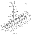
- Figures 1-7 show the preferred embodiment of the apparatus of the present invention designated generally by the numeral 10 in Figures 1 and 7.
- provisional fixation apparatus 10 is shown at a fracture site 22 in patient's bone tissue 20.
- the bone tissue 20 includes segments 21A, 21B on opposite sides of fracture 22.
- a drill 11 having a drill chuck 12 is used to insert a provisional fixation pin 13.
- the provisional fixation pin 13 includes an upper or proximal section 17 that is unthreaded, an enlarged diameter middle section 16, and a lower or distal section 15 having cutting tip 14.
- the provisional fixation pin 13 has a distal section 15 that is externally threaded.
- Cutting tip 14 can include three flat surfaces 14A and three cutting blades 14B.
- the drill 11 and drill chuck 12 rotate in the direction of curved arrow 18 so that the cutting tip 14 cuts into the underlying bone tissue 20 embedding the externally threaded distal section 15 as shown in Figure 7.
- the provisional fixation pin 13 provides a lower externally threaded distal section 15 of a smaller diameter that is much smaller in diameter than the diameter D of the circular openings 14 in bone plate 19.
- bone plate 19 has end portions 23, 24.
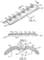
- a sectional view of bone plate 19 shows that there are a plurality of openings 25-30, each of which includes a circular opening 34 and a countersunk surface portion 33.
- the diameter D shown in Figure 4 is of a diameter of 7mm for example, while the diameter of external threaded distal section 15 is about 1.5 mm in diameter.
- This smaller diameter enables the surgeon to provisionally affix the bone plate 19 to the underlying tissue 20 without invading the bone tissue with a very large opening such as is formed by a conventional bone screw 39 having a shank diameter closely approaching the diameter "D" of opening 34 in Figure 4.
- Each of the openings 25-30 of bone plate 19 will eventually be occupied by a bone screw 39 having a countersunk head 40 portion.
- the provisional fixation pins 13 of the present invention enable some reduction without significantly compromising the underlying bone tissue 20.
- Bone plate 19 has end portions 23 and 24.
- the bone plate 19 also provides an inner concave surface 31 and an outer convex surface 32.
- Each of the openings 25-30 includes the circular opening 34 that communicates with both the upper convex surface 32 and the lower concave surface 31.
- the countersunk portion 33 communicates only with the upper convex surface 32.
- both the provisional fixation pin 13 and a bone screw will preferably track the path of central axis 35 of opening 28 (see Figure 4) or the central axis of any of the other selected openings 25-30.
- the enlarged diameter section 16 of provisional fixation pin 13 has a lower convexity shaped annular surface 36.
- surface 36 conforms to and fits surface 33 of bone plate 19.
- Annular line 37 defines a border in between the lower annular surface 36 and upper annular surface 38 of enlarged diameter section 16.
- FIGs 8-11 the method of using the apparatus of the present invention is shown.
- the bone plate 19 has been placed in a provisional selected position at fracture site 22.
- five of the openings 25, 26, 28, 29 and 30 are unoccupied.
- two of the openings 27 and 28 are next to the but on opposite sides of the fracture site 22 as shown.
- a single provisional fixation pin 13 has been inserted by rotating the pin 13 in the direction of arrow 18. Rotation continues until the large diameter section 16 occupies the opening 27, the annular surface 36 abutting and conforming to the countersunk surface 33 of the selected bone plate opening 25, 26, 27, 28, 29, 30.
- Part Number Description 10 provisional fixation apparatus 11 drill 12 drill chuck 13 provisional fixation pin 14 drill distal tip 14A flat surface 14B cutting edge 15 externally threaded distal section 16 enlarged section 17 unthreaded proximal section 18 curved arrow 19 bone plate 20 patient's bone tissue 21A bone segment 21B bone segment 22 fracture site 23 end portion 24 end portion 25 opening 26 opening 27 opening 28 opening 29 opening 30 opening 31 concave surface 32 convex surface 33 countersunk surface 34 circular opening 35 central axis 36 lower annular surface 37 annular line 38 upper annular surface 39 bone screw 40 head
Landscapes
- Health & Medical Sciences (AREA)
- Orthopedic Medicine & Surgery (AREA)
- Surgery (AREA)
- Life Sciences & Earth Sciences (AREA)
- Molecular Biology (AREA)
- Animal Behavior & Ethology (AREA)
- Engineering & Computer Science (AREA)
- Biomedical Technology (AREA)
- Heart & Thoracic Surgery (AREA)
- Medical Informatics (AREA)
- Neurology (AREA)
- Nuclear Medicine, Radiotherapy & Molecular Imaging (AREA)
- General Health & Medical Sciences (AREA)
- Public Health (AREA)
- Veterinary Medicine (AREA)
- Surgical Instruments (AREA)
- Prostheses (AREA)
- Connection Of Plates (AREA)
- Dowels (AREA)
- Superstructure Of Vehicle (AREA)
Claims (10)
- Eine Knochenplattenvorrichtung (10) zum Instandsetzen eines frakturierten Knochens (20) eines Patienten an einer Frakturstelle (22), die Folgendes beinhaltet:a) eine Knochenplatte (19), die eine obere und untere Fläche und eine Vielzahl von gesenkten Öffnungen (25, 26, 27, 28, 29, 30) durch die Platte (19) aufweist, wobei jede Öffnung (25, 26, 27, 28, 29, 30) eine gesenkte konkave Fläche (31) umfasst, die mit der oberen Fläche der Platte (19) in Verbindung steht;b) eine Vielzahl von vorläufigen Knochenstiften (13), die jeweils in die Vielzahl von Öffnungen (25, 26, 27, 28, 29, 30) passen, wobei jeder Stift einen distalen Abschnitt (15) mit einer Bohrungsspitze (14), einen proximalen Abschnitt (17) und einen vergrößerten Durchmesserabschnitt (16) zwischen dem proximalen (17) und dem distalen (15) Abschnitt aufweist;c) den vergrößerten Durchmesserabschnitt (16), der eine konvexe ringförmige Fläche (32) aufweist, die sich bei Gebrauch eng an die gesenkte konkave Fläche (31) einer Öffnung (25, 26, 27, 28, 29, 30) anpasst;d) eine Vielzahl von Knochenschrauben (39), die einen Kopf (40) und einen Gewindeschaft aufweisen, wobei der Durchmesser des Gewindeschafts viel größer als der Durchmesser des distalen Abschnitts des vorläufigen Knochenstifts (13) ist; unde) wobei der Kopf jeder Knochenschraube ungefähr vom gleichen Durchmesser wie der vergrößerte Durchmesserabschnitt des vorläufigen Knochenstifts (13) ist, dadurch gekennzeichnet, dass der distale Abschnitt (15) jedes vorläufigen Knochenstifts (13) gewunden ist.
- Knochenplattenvorrichtung (10) gemäß Anspruch 1, wobei der Durchmesser des distalen Abschnitts (15) jedes vorläufigen Stifts (13) ungefähr gleich des Durchmessers des proximalen Abschnitts (17) ist.
- Knochenplattenvorrichtung (10) gemäß einem der vorhergehenden Ansprüche, wobei der vergrößerte Durchmesserabschnitt (16) von einem der vorläufigen Knochenstifte (13) ungefähr von der gleichen Größe und Form wie der Kopf einer der Knochenschrauben (39) ist.
- Knochenplattenvorrichtung (10) gemäß einem der vorhergehenden Ansprüche, wobei der vergrößerte Durchmesserabschnitt (16) des vorläufigen Knochenstifts einen Durchmesser aufweist, der größer als der Durchmesser des distalen Abschnitts (15) ist.
- Knochenplattenvorrichtung (10) gemäß einem der vorhergehenden Ansprüche, wobei die gesenkten Öffnungen (25, 26, 27, 28, 29, 30) jeweils eine konkave gesenkte Fläche (31), die mit der oberen Knochenplattenfläche in Verbindung steht, und eine im Allgemeinen kreisförmige Öffnung, die mit der unteren Knochenplattenfläche in Verbindung steht, umfassen.
- Knochenplattenvorrichtung (10) gemäß einem der vorhergehenden Ansprüche, wobei der distale Abschnitt (15) des vorläufigen Knochenstifts einen Durchmesser von zwischen 1 und 3 mm aufweist.
- Knochenplattenvorrichtung (10) gemäß einem der vorhergehenden Ansprüche, wobei der proximale Abschnitt (17) des vorläufigen Knochenstifts einen Durchmesser von zwischen 1 und 8 mm aufweist.
- Knochenplattenvorrichtung (10) gemäß einem der vorhergehenden Ansprüche, wobei der vergrößerte Durchmesserabschnitt (16) einen Durchmesser von zwischen 4 und 10 mm aufweist.
- Knochenplattenvorrichtung (10) gemäß einem der vorhergehenden Ansprüche, wobei der distale Abschnitt (15) des vorläufigen Knochenstifts außen mit einem feingängigen Gewindemuster gewunden ist.
- Ein Verfahren zur Herstellung einer Knochenplattenvorrichtung (10), das folgenden Schritt beinhaltet:wobei die Vielzahl von Knochenschrauben (39) einen Kopf (40) und einen Gewindeschaft aufweist, wobei der Durchmesser des Gewindeschafts viel grösser als der Durchmesser des distalen Abschnitts (15) des vorläufigen Knochenstifts (13) ist, und wobei der Kopf (40) jeder Knochenschraube (39) ungefähr vom gleichen Durchmesser wie der vergrößerte Durchmesserabschnitt (16) des vorläufigen Knochenstifts (13) ist.Zusammensetzen einer Knochenplatte (19) mit einer Vielzahl von vorläufigen Knochenstiften (13) und einer Vielzahl von Knochenschrauben (39), wobei die Knochenplatte (19) eine obere und untere Fläche und eine Vielzahl von gesenkten Öffnungen durch die Platte (19) aufweist, wobei jede Öffnung eine gesenkte konkave Fläche (31) umfasst, die mit der oberen Fläche der Platte (19) in Verbindung steht, und die Vielzahl von vorläufigen Knochenstiften (13), die jeweils in die Vielzahl von Öffnungen (25, 26, 27, 28, 29, 30) passen, alle einen gewundenen distalen Abschnitt (15) mit einer Bohrungsspitze (14), einen proximalen Abschnitt und einen vergrößerten Durchmesserabschnitt zwischen dem proximalen und dem distalen Abschnitt aufweisen, und wobei der vergrößerte Durchmesserabschnitt (16) eine konvexe ringförmige Fläche (32) aufweist, die sich bei Gebrauch eng an die gesenkte konkave Fläche (31) einer Öffnung (25, 26, 27, 28, 29, 30) anpasst; und
Applications Claiming Priority (3)
| Application Number | Priority Date | Filing Date | Title |
|---|---|---|---|
| US09/090,117 US5968046A (en) | 1998-06-04 | 1998-06-04 | Provisional fixation pin |
| US90117 | 1998-06-04 | ||
| PCT/US1999/012438 WO1999062419A1 (en) | 1998-06-04 | 1999-06-03 | Provisional bone plate fixation pin |
Publications (2)
| Publication Number | Publication Date |
|---|---|
| EP1083837A1 EP1083837A1 (de) | 2001-03-21 |
| EP1083837B1 true EP1083837B1 (de) | 2003-11-05 |
Family
ID=22221401
Family Applications (1)
| Application Number | Title | Priority Date | Filing Date |
|---|---|---|---|
| EP99927206A Expired - Lifetime EP1083837B1 (de) | 1998-06-04 | 1999-06-03 | Stift zur provisorischen befestigung einer knochenplatte |
Country Status (11)
| Country | Link |
|---|---|
| US (1) | US5968046A (de) |
| EP (1) | EP1083837B1 (de) |
| JP (1) | JP4080160B2 (de) |
| AT (1) | ATE253328T1 (de) |
| AU (1) | AU743016B2 (de) |
| CA (1) | CA2331900C (de) |
| DE (1) | DE69912600T2 (de) |
| DK (1) | DK1083837T3 (de) |
| ES (1) | ES2209450T3 (de) |
| PT (1) | PT1083837E (de) |
| WO (1) | WO1999062419A1 (de) |
Families Citing this family (93)
| Publication number | Priority date | Publication date | Assignee | Title |
|---|---|---|---|---|
| US5713921A (en) | 1996-03-29 | 1998-02-03 | Bonutti; Peter M. | Suture anchor |
| US5919234A (en) * | 1996-08-19 | 1999-07-06 | Macropore, Inc. | Resorbable, macro-porous, non-collapsing and flexible membrane barrier for skeletal repair and regeneration |
| CA2318865A1 (en) * | 1998-01-23 | 1999-07-29 | Marcopore, Inc. | Resorbable, macro-porous, non-collapsing and flexible membrane barrier for skeletal repair and regeneration |
| US6045551A (en) | 1998-02-06 | 2000-04-04 | Bonutti; Peter M. | Bone suture |
| US6447516B1 (en) | 1999-08-09 | 2002-09-10 | Peter M. Bonutti | Method of securing tissue |
| US6368343B1 (en) | 2000-03-13 | 2002-04-09 | Peter M. Bonutti | Method of using ultrasonic vibration to secure body tissue |
| US6635073B2 (en) | 2000-05-03 | 2003-10-21 | Peter M. Bonutti | Method of securing body tissue |
| US20040153073A1 (en) | 2000-02-01 | 2004-08-05 | Hand Innovations, Inc. | Orthopedic fixation system including plate element with threaded holes having divergent axes |
| US6767351B2 (en) | 2000-02-01 | 2004-07-27 | Hand Innovations, Inc. | Fixation system with multidirectional stabilization pegs |
| US6706046B2 (en) | 2000-02-01 | 2004-03-16 | Hand Innovations, Inc. | Intramedullary fixation device for metaphyseal long bone fractures and methods of using the same |
| US7695502B2 (en) | 2000-02-01 | 2010-04-13 | Depuy Products, Inc. | Bone stabilization system including plate having fixed-angle holes together with unidirectional locking screws and surgeon-directed locking screws |
| US7857838B2 (en) | 2003-03-27 | 2010-12-28 | Depuy Products, Inc. | Anatomical distal radius fracture fixation plate |
| EP1257219B1 (de) * | 2000-02-24 | 2012-01-18 | Stryker Instruments | Vorrichtung zur Erwärmung von bioabsorbierbaren Platten |
| US9138222B2 (en) | 2000-03-13 | 2015-09-22 | P Tech, Llc | Method and device for securing body tissue |
| US7094251B2 (en) | 2002-08-27 | 2006-08-22 | Marctec, Llc. | Apparatus and method for securing a suture |
| CN1184932C (zh) * | 2000-06-26 | 2005-01-19 | 库尔斯恩蒂斯股份公司 | 用于骨接合的骨板 |
| US7717945B2 (en) | 2002-07-22 | 2010-05-18 | Acumed Llc | Orthopedic systems |
| US20050240187A1 (en) | 2004-04-22 | 2005-10-27 | Huebner Randall J | Expanded fixation of bones |
| GB0114659D0 (en) * | 2001-06-15 | 2001-08-08 | Finsbury Dev Ltd | Device |
| US7766947B2 (en) | 2001-10-31 | 2010-08-03 | Ortho Development Corporation | Cervical plate for stabilizing the human spine |
| US6679883B2 (en) | 2001-10-31 | 2004-01-20 | Ortho Development Corporation | Cervical plate for stabilizing the human spine |
| US6719765B2 (en) | 2001-12-03 | 2004-04-13 | Bonutti 2003 Trust-A | Magnetic suturing system and method |
| US9155544B2 (en) | 2002-03-20 | 2015-10-13 | P Tech, Llc | Robotic systems and methods |
| US6746448B2 (en) | 2002-05-30 | 2004-06-08 | Millennium Medical Technologies, Inc. | Outrigger for bone fixator |
| ATE488189T1 (de) * | 2002-07-22 | 2010-12-15 | Acumed Llc | Knochenfusionssystem |
| US7250054B2 (en) * | 2002-08-28 | 2007-07-31 | Smith & Nephew, Inc. | Systems, methods, and apparatuses for clamping and reclamping an orthopedic surgical cable |
| US7179260B2 (en) * | 2003-09-29 | 2007-02-20 | Smith & Nephew, Inc. | Bone plates and bone plate assemblies |
| JP4028552B2 (ja) * | 2002-11-19 | 2007-12-26 | アキュームド・エルエルシー | 調節可能な骨プレート |
| US7517350B2 (en) * | 2002-11-20 | 2009-04-14 | Orthopediatrics Corp. | Convertible threaded compression device and method of use |
| US7641677B2 (en) * | 2002-11-20 | 2010-01-05 | Orthopediatrics Corp. | Compression bone fragment wire |
| US7811312B2 (en) | 2002-12-04 | 2010-10-12 | Morphographics, Lc | Bone alignment implant and method of use |
| US7780664B2 (en) | 2002-12-10 | 2010-08-24 | Depuy Products, Inc. | Endosteal nail |
| US7497864B2 (en) | 2003-04-30 | 2009-03-03 | Marctec, Llc. | Tissue fastener and methods for using same |
| US7951176B2 (en) | 2003-05-30 | 2011-05-31 | Synthes Usa, Llc | Bone plate |
| CN100553577C (zh) * | 2003-06-20 | 2009-10-28 | 精密医疗责任有限公司 | 用于在手术中对接骨板攻螺纹的系统 |
| US11259851B2 (en) | 2003-08-26 | 2022-03-01 | DePuy Synthes Products, Inc. | Bone plate |
| DE20321151U1 (de) | 2003-08-26 | 2006-09-07 | Synthes Gmbh | Knochenplatte |
| US7635365B2 (en) | 2003-08-28 | 2009-12-22 | Ellis Thomas J | Bone plates |
| US8105367B2 (en) | 2003-09-29 | 2012-01-31 | Smith & Nephew, Inc. | Bone plate and bone plate assemblies including polyaxial fasteners |
| WO2005037114A1 (en) * | 2003-10-17 | 2005-04-28 | Acumed Llc | Systems for distal radius fixation |
| WO2005041812A2 (en) * | 2003-10-22 | 2005-05-12 | Implant Brace, Inc. | Implantable brace for a fracture and methods |
| US7766920B2 (en) * | 2003-11-26 | 2010-08-03 | Synthes Usa, Llc | Cannulated fastener system |
| US11291484B2 (en) | 2004-01-26 | 2022-04-05 | DePuy Synthes Products, Inc. | Highly-versatile variable-angle bone plate system |
| US8574268B2 (en) | 2004-01-26 | 2013-11-05 | DePuy Synthes Product, LLC | Highly-versatile variable-angle bone plate system |
| US20080039873A1 (en) | 2004-03-09 | 2008-02-14 | Marctec, Llc. | Method and device for securing body tissue |
| US7604643B2 (en) * | 2004-04-06 | 2009-10-20 | Synthes Usa, Llc | Adjustable tool for cannulated fasteners |
| US7229445B2 (en) | 2004-06-21 | 2007-06-12 | Synthes (Usa) | Bone plate with bladed portion |
| US20060149265A1 (en) * | 2004-09-07 | 2006-07-06 | Anthony James | Minimal thickness bone plate locking mechanism |
| US8469966B2 (en) * | 2004-09-23 | 2013-06-25 | Smith & Nephew, Inc. | Systems, methods, and apparatuses for tensioning an orthopedic surgical cable |
| US20060089646A1 (en) | 2004-10-26 | 2006-04-27 | Bonutti Peter M | Devices and methods for stabilizing tissue and implants |
| US9271766B2 (en) | 2004-10-26 | 2016-03-01 | P Tech, Llc | Devices and methods for stabilizing tissue and implants |
| US9463012B2 (en) | 2004-10-26 | 2016-10-11 | P Tech, Llc | Apparatus for guiding and positioning an implant |
| US9173647B2 (en) | 2004-10-26 | 2015-11-03 | P Tech, Llc | Tissue fixation system |
| US9089323B2 (en) | 2005-02-22 | 2015-07-28 | P Tech, Llc | Device and method for securing body tissue |
| US7763071B2 (en) * | 2005-03-04 | 2010-07-27 | Rti Biologics, Inc. | Bone block assemblies and their use in assembled bone-tendon-bone grafts |
| US8470038B2 (en) | 2005-03-04 | 2013-06-25 | Rti Biologics, Inc. | Adjustable and fixed assembled bone-tendon-bone graft |
| US7727278B2 (en) * | 2005-03-04 | 2010-06-01 | Rti Biologics, Inc. | Self fixing assembled bone-tendon-bone graft |
| US7776089B2 (en) * | 2005-03-04 | 2010-08-17 | Rti Biologics, Inc. | Assembled bone-tendon-bone grafts |
| CN101272743B (zh) | 2005-07-25 | 2011-01-26 | 史密夫和内修有限公司 | 使用多轴式板的系统 |
| US8382807B2 (en) | 2005-07-25 | 2013-02-26 | Smith & Nephew, Inc. | Systems and methods for using polyaxial plates |
| US7905909B2 (en) | 2005-09-19 | 2011-03-15 | Depuy Products, Inc. | Bone stabilization system including multi-directional threaded fixation element |
| US7967820B2 (en) | 2006-02-07 | 2011-06-28 | P Tech, Llc. | Methods and devices for trauma welding |
| US11253296B2 (en) | 2006-02-07 | 2022-02-22 | P Tech, Llc | Methods and devices for intracorporeal bonding of implants with thermal energy |
| US11278331B2 (en) | 2006-02-07 | 2022-03-22 | P Tech Llc | Method and devices for intracorporeal bonding of implants with thermal energy |
| US8496657B2 (en) | 2006-02-07 | 2013-07-30 | P Tech, Llc. | Methods for utilizing vibratory energy to weld, stake and/or remove implants |
| US7951178B2 (en) * | 2006-04-03 | 2011-05-31 | Acumed Llc | Bone plates with hybrid apertures |
| US7985221B2 (en) * | 2006-04-20 | 2011-07-26 | Millennium Medical Technologies, Inc. | External fixator |
| US11246638B2 (en) | 2006-05-03 | 2022-02-15 | P Tech, Llc | Methods and devices for utilizing bondable materials |
| US8617185B2 (en) | 2007-02-13 | 2013-12-31 | P Tech, Llc. | Fixation device |
| US7722611B2 (en) * | 2007-03-05 | 2010-05-25 | Depuy Products, Inc. | Method of treating a clavicle fracture |
| US8273111B2 (en) | 2008-07-02 | 2012-09-25 | Ebi, Llc | Growth control device |
| US20100094352A1 (en) * | 2008-10-10 | 2010-04-15 | Andrew Iott | Bone screw |
| WO2010099222A1 (en) | 2009-02-24 | 2010-09-02 | P Tech, Llc | Methods and devices for utilizing bondable materials |
| JP5588876B2 (ja) * | 2009-06-03 | 2014-09-10 | タキロン株式会社 | 骨用ネジセット |
| US8162996B2 (en) * | 2009-10-28 | 2012-04-24 | Orthopro Llc | Methods for repairing bone discontinuities |
| US9011507B2 (en) | 2009-10-28 | 2015-04-21 | Orthopro Llc | Compression plate kit and methods for repairing bone discontinuities |
| US8568417B2 (en) | 2009-12-18 | 2013-10-29 | Charles River Engineering Solutions And Technologies, Llc | Articulating tool and methods of using |
| WO2012009511A1 (en) | 2010-07-14 | 2012-01-19 | Synthes Usa, Llc | Assemblies for aligning a bone fixation plate |
| CA2839423A1 (en) | 2011-06-15 | 2012-12-20 | Smith & Nephew, Inc. | Variable angle locking implant |
| GB2509668B (en) | 2011-09-30 | 2018-04-11 | Acute Innovations Llc | Bone fixation system with opposed mounting portions |
| WO2013113015A1 (en) | 2012-01-26 | 2013-08-01 | Acute Innovations Llc | Clip for rib stabilization |
| US10076377B2 (en) | 2013-01-05 | 2018-09-18 | P Tech, Llc | Fixation systems and methods |
| US10993750B2 (en) | 2015-09-18 | 2021-05-04 | Smith & Nephew, Inc. | Bone plate |
| US10058393B2 (en) | 2015-10-21 | 2018-08-28 | P Tech, Llc | Systems and methods for navigation and visualization |
| US10820930B2 (en) | 2016-09-08 | 2020-11-03 | DePuy Synthes Products, Inc. | Variable angle bone plate |
| US10905476B2 (en) | 2016-09-08 | 2021-02-02 | DePuy Synthes Products, Inc. | Variable angle bone plate |
| US10624686B2 (en) | 2016-09-08 | 2020-04-21 | DePuy Synthes Products, Inc. | Variable angel bone plate |
| US10932823B2 (en) * | 2017-10-25 | 2021-03-02 | Life Spine, Inc. | Facet plate for implant expulsion prevention and method of installation |
| US11026727B2 (en) | 2018-03-20 | 2021-06-08 | DePuy Synthes Products, Inc. | Bone plate with form-fitting variable-angle locking hole |
| US10772665B2 (en) | 2018-03-29 | 2020-09-15 | DePuy Synthes Products, Inc. | Locking structures for affixing bone anchors to a bone plate, and related systems and methods |
| US11013541B2 (en) | 2018-04-30 | 2021-05-25 | DePuy Synthes Products, Inc. | Threaded locking structures for affixing bone anchors to a bone plate, and related systems and methods |
| US10925651B2 (en) | 2018-12-21 | 2021-02-23 | DePuy Synthes Products, Inc. | Implant having locking holes with collection cavity for shavings |
| JP7323743B2 (ja) * | 2019-02-08 | 2023-08-09 | 日本メディカルネクスト株式会社 | 仮止めピン |
Family Cites Families (10)
| Publication number | Priority date | Publication date | Assignee | Title |
|---|---|---|---|---|
| US3915162A (en) * | 1974-02-13 | 1975-10-28 | Peter S Miller | Orthopedic pin identification means |
| FR2667913B3 (fr) * | 1990-10-16 | 1992-12-31 | Biomecanique Integree | Systeme pour l'assemblage d'au moins deux elements par vis ou analogue. |
| US5129899A (en) * | 1991-03-27 | 1992-07-14 | Smith & Nephew Richards Inc. | Bone fixation apparatus |
| US5423826A (en) * | 1993-02-05 | 1995-06-13 | Danek Medical, Inc. | Anterior cervical plate holder/drill guide and method of use |
| DE4406374C2 (de) * | 1993-03-25 | 1995-07-13 | Pennig Dietmar | Fixationsstift für Osteosynthesearbeiten |
| JP3442111B2 (ja) | 1993-09-14 | 2003-09-02 | 株式会社ソニー・コンピュータエンタテインメント | 画像圧縮装置,画像再生装置及び描画装置 |
| DE19511268A1 (de) * | 1995-03-27 | 1996-10-02 | Johannes Franz Dr Med Hoenig | Osteosyntheseplatte |
| DE29515125U1 (de) * | 1995-09-21 | 1995-12-21 | Pennig Dietmar | Fixationsstift für Osteosynthesearbeiten |
| US5676667A (en) * | 1995-12-08 | 1997-10-14 | Hausman; Michael | Bone fixation apparatus and method |
| US5700267A (en) * | 1996-08-15 | 1997-12-23 | Kinetikos Medical Incorporated | Method for repairing bone fractures using bone-lock system |
-
1998
- 1998-06-04 US US09/090,117 patent/US5968046A/en not_active Expired - Lifetime
-
1999
- 1999-06-03 AT AT99927206T patent/ATE253328T1/de not_active IP Right Cessation
- 1999-06-03 WO PCT/US1999/012438 patent/WO1999062419A1/en active IP Right Grant
- 1999-06-03 AU AU44170/99A patent/AU743016B2/en not_active Ceased
- 1999-06-03 ES ES99927206T patent/ES2209450T3/es not_active Expired - Lifetime
- 1999-06-03 EP EP99927206A patent/EP1083837B1/de not_active Expired - Lifetime
- 1999-06-03 JP JP2000551682A patent/JP4080160B2/ja not_active Expired - Fee Related
- 1999-06-03 DE DE69912600T patent/DE69912600T2/de not_active Expired - Lifetime
- 1999-06-03 DK DK99927206T patent/DK1083837T3/da active
- 1999-06-03 CA CA002331900A patent/CA2331900C/en not_active Expired - Fee Related
- 1999-06-03 PT PT99927206T patent/PT1083837E/pt unknown
Also Published As
| Publication number | Publication date |
|---|---|
| AU4417099A (en) | 1999-12-20 |
| EP1083837A1 (de) | 2001-03-21 |
| PT1083837E (pt) | 2004-03-31 |
| CA2331900A1 (en) | 1999-12-09 |
| DK1083837T3 (da) | 2004-03-15 |
| JP4080160B2 (ja) | 2008-04-23 |
| CA2331900C (en) | 2007-04-24 |
| DE69912600D1 (de) | 2003-12-11 |
| ATE253328T1 (de) | 2003-11-15 |
| US5968046A (en) | 1999-10-19 |
| JP2002516699A (ja) | 2002-06-11 |
| DE69912600T2 (de) | 2004-09-30 |
| WO1999062419A1 (en) | 1999-12-09 |
| ES2209450T3 (es) | 2004-06-16 |
| AU743016B2 (en) | 2002-01-17 |
Similar Documents
| Publication | Publication Date | Title |
|---|---|---|
| EP1083837B1 (de) | Stift zur provisorischen befestigung einer knochenplatte | |
| US5201733A (en) | Method and apparatus for internal fixation of fractures | |
| CA2596266C (en) | Nail plate system | |
| EP1507486B1 (de) | Intramedulläre fixiervorrichtung für metaphyseale röhrenknochenfrakturen | |
| JP4368560B2 (ja) | 多軸式固定プレート | |
| EP1713410B1 (de) | Proximale Humerusknochenplatte mit einem in einer Bohrung rotatif arretierten Pfosten mit starrem Querbalken | |
| US7927333B2 (en) | System for the minimally invasive treatment of a bone fracture, especially of a proximal humeral or femoral fracture | |
| CA2707241C (en) | Distal tibia plating system | |
| EP1393689B1 (de) | Platte und Schraube für die vordere Halswirbelsäule | |
| US6712818B1 (en) | Method for connecting adjacent vertebral bodies of a human spine with a plating system | |
| AU2005304439B2 (en) | Endosteal nail | |
| US20060161156A1 (en) | Fracture fixation device | |
| US20060189987A1 (en) | Nail plate | |
| US20060149257A1 (en) | Fracture fixation device | |
| CA2646726A1 (en) | Nail plate and jig therefor | |
| US11877719B2 (en) | Bone plate with orientation indicator and positional adjustment mechanism | |
| EP4268740A1 (de) | Tauch-/gestängeschraube |
Legal Events
| Date | Code | Title | Description |
|---|---|---|---|
| PUAI | Public reference made under article 153(3) epc to a published international application that has entered the european phase |
Free format text: ORIGINAL CODE: 0009012 |
|
| 17P | Request for examination filed |
Effective date: 20001114 |
|
| AK | Designated contracting states |
Kind code of ref document: A1 Designated state(s): AT BE CH CY DE DK ES FI FR GB GR IE IT LI LU MC NL PT SE |
|
| GRAH | Despatch of communication of intention to grant a patent |
Free format text: ORIGINAL CODE: EPIDOS IGRA |
|
| GRAS | Grant fee paid |
Free format text: ORIGINAL CODE: EPIDOSNIGR3 |
|
| GRAA | (expected) grant |
Free format text: ORIGINAL CODE: 0009210 |
|
| AK | Designated contracting states |
Kind code of ref document: B1 Designated state(s): AT BE CH CY DE DK ES FI FR GB GR IE IT LI LU MC NL PT SE |
|
| PG25 | Lapsed in a contracting state [announced via postgrant information from national office to epo] |
Ref country code: CY Free format text: LAPSE BECAUSE OF FAILURE TO SUBMIT A TRANSLATION OF THE DESCRIPTION OR TO PAY THE FEE WITHIN THE PRESCRIBED TIME-LIMIT Effective date: 20031105 |
|
| REG | Reference to a national code |
Ref country code: GB Ref legal event code: FG4D |
|
| REG | Reference to a national code |
Ref country code: CH Ref legal event code: EP |
|
| REF | Corresponds to: |
Ref document number: 69912600 Country of ref document: DE Date of ref document: 20031211 Kind code of ref document: P |
|
| REG | Reference to a national code |
Ref country code: IE Ref legal event code: FG4D |
|
| REG | Reference to a national code |
Ref country code: SE Ref legal event code: TRGR |
|
| REG | Reference to a national code |
Ref country code: GR Ref legal event code: EP Ref document number: 20040400142 Country of ref document: GR |
|
| REG | Reference to a national code |
Ref country code: CH Ref legal event code: NV Representative=s name: ROSENICH PAUL; GISLER CHRISTIAN PATENTBUERO PAUL R |
|
| REG | Reference to a national code |
Ref country code: DK Ref legal event code: T3 |
|
| REG | Reference to a national code |
Ref country code: PT Ref legal event code: SC4A Free format text: AVAILABILITY OF NATIONAL TRANSLATION Effective date: 20040130 |
|
| PG25 | Lapsed in a contracting state [announced via postgrant information from national office to epo] |
Ref country code: LU Free format text: LAPSE BECAUSE OF NON-PAYMENT OF DUE FEES Effective date: 20040603 Ref country code: IE Free format text: LAPSE BECAUSE OF NON-PAYMENT OF DUE FEES Effective date: 20040603 Ref country code: FI Free format text: LAPSE BECAUSE OF NON-PAYMENT OF DUE FEES Effective date: 20040603 Ref country code: AT Free format text: LAPSE BECAUSE OF NON-PAYMENT OF DUE FEES Effective date: 20040603 |
|
| REG | Reference to a national code |
Ref country code: ES Ref legal event code: FG2A Ref document number: 2209450 Country of ref document: ES Kind code of ref document: T3 |
|
| PG25 | Lapsed in a contracting state [announced via postgrant information from national office to epo] |
Ref country code: MC Free format text: LAPSE BECAUSE OF NON-PAYMENT OF DUE FEES Effective date: 20040630 Ref country code: DK Free format text: LAPSE BECAUSE OF NON-PAYMENT OF DUE FEES Effective date: 20040630 |
|
| ET | Fr: translation filed | ||
| PLBE | No opposition filed within time limit |
Free format text: ORIGINAL CODE: 0009261 |
|
| STAA | Information on the status of an ep patent application or granted ep patent |
Free format text: STATUS: NO OPPOSITION FILED WITHIN TIME LIMIT |
|
| 26N | No opposition filed |
Effective date: 20040806 |
|
| PG25 | Lapsed in a contracting state [announced via postgrant information from national office to epo] |
Ref country code: PT Free format text: LAPSE BECAUSE OF NON-PAYMENT OF DUE FEES Effective date: 20041203 |
|
| PG25 | Lapsed in a contracting state [announced via postgrant information from national office to epo] |
Ref country code: NL Free format text: LAPSE BECAUSE OF NON-PAYMENT OF DUE FEES Effective date: 20050101 |
|
| PG25 | Lapsed in a contracting state [announced via postgrant information from national office to epo] |
Ref country code: GR Free format text: LAPSE BECAUSE OF NON-PAYMENT OF DUE FEES Effective date: 20050105 |
|
| REG | Reference to a national code |
Ref country code: DK Ref legal event code: EBP |
|
| REG | Reference to a national code |
Ref country code: PT Ref legal event code: MM4A Free format text: LAPSE DUE TO NON-PAYMENT OF FEES Effective date: 20041203 |
|
| NLV4 | Nl: lapsed or anulled due to non-payment of the annual fee |
Effective date: 20050101 |
|
| REG | Reference to a national code |
Ref country code: IE Ref legal event code: MM4A |
|
| REG | Reference to a national code |
Ref country code: SE Ref legal event code: RPOT |
|
| REG | Reference to a national code |
Ref country code: FR Ref legal event code: PLFP Year of fee payment: 17 |
|
| REG | Reference to a national code |
Ref country code: FR Ref legal event code: PLFP Year of fee payment: 18 |
|
| REG | Reference to a national code |
Ref country code: FR Ref legal event code: PLFP Year of fee payment: 19 |
|
| PGFP | Annual fee paid to national office [announced via postgrant information from national office to epo] |
Ref country code: CH Payment date: 20170613 Year of fee payment: 19 Ref country code: FR Payment date: 20170511 Year of fee payment: 19 Ref country code: DE Payment date: 20170530 Year of fee payment: 19 Ref country code: GB Payment date: 20170531 Year of fee payment: 19 |
|
| PGFP | Annual fee paid to national office [announced via postgrant information from national office to epo] |
Ref country code: IT Payment date: 20170619 Year of fee payment: 19 Ref country code: SE Payment date: 20170613 Year of fee payment: 19 Ref country code: BE Payment date: 20170424 Year of fee payment: 19 |
|
| PGFP | Annual fee paid to national office [announced via postgrant information from national office to epo] |
Ref country code: ES Payment date: 20170704 Year of fee payment: 19 |
|
| REG | Reference to a national code |
Ref country code: DE Ref legal event code: R119 Ref document number: 69912600 Country of ref document: DE |
|
| REG | Reference to a national code |
Ref country code: SE Ref legal event code: EUG |
|
| PG25 | Lapsed in a contracting state [announced via postgrant information from national office to epo] |
Ref country code: SE Free format text: LAPSE BECAUSE OF NON-PAYMENT OF DUE FEES Effective date: 20180604 |
|
| REG | Reference to a national code |
Ref country code: CH Ref legal event code: PL |
|
| GBPC | Gb: european patent ceased through non-payment of renewal fee |
Effective date: 20180603 |
|
| REG | Reference to a national code |
Ref country code: BE Ref legal event code: MM Effective date: 20180630 |
|
| PG25 | Lapsed in a contracting state [announced via postgrant information from national office to epo] |
Ref country code: CH Free format text: LAPSE BECAUSE OF NON-PAYMENT OF DUE FEES Effective date: 20180630 Ref country code: FR Free format text: LAPSE BECAUSE OF NON-PAYMENT OF DUE FEES Effective date: 20180630 Ref country code: DE Free format text: LAPSE BECAUSE OF NON-PAYMENT OF DUE FEES Effective date: 20190101 Ref country code: IT Free format text: LAPSE BECAUSE OF NON-PAYMENT OF DUE FEES Effective date: 20180603 Ref country code: GB Free format text: LAPSE BECAUSE OF NON-PAYMENT OF DUE FEES Effective date: 20180603 Ref country code: LI Free format text: LAPSE BECAUSE OF NON-PAYMENT OF DUE FEES Effective date: 20180630 |
|
| PG25 | Lapsed in a contracting state [announced via postgrant information from national office to epo] |
Ref country code: BE Free format text: LAPSE BECAUSE OF NON-PAYMENT OF DUE FEES Effective date: 20180630 |
|
| REG | Reference to a national code |
Ref country code: ES Ref legal event code: FD2A Effective date: 20190916 |
|
| PG25 | Lapsed in a contracting state [announced via postgrant information from national office to epo] |
Ref country code: ES Free format text: LAPSE BECAUSE OF NON-PAYMENT OF DUE FEES Effective date: 20180604 |