EP1083619A2 - Battery pack - Google Patents
Battery pack Download PDFInfo
- Publication number
- EP1083619A2 EP1083619A2 EP00402494A EP00402494A EP1083619A2 EP 1083619 A2 EP1083619 A2 EP 1083619A2 EP 00402494 A EP00402494 A EP 00402494A EP 00402494 A EP00402494 A EP 00402494A EP 1083619 A2 EP1083619 A2 EP 1083619A2
- Authority
- EP
- European Patent Office
- Prior art keywords
- battery cell
- leakage
- battery pack
- battery
- electrolyte solution
- Prior art date
- Legal status (The legal status is an assumption and is not a legal conclusion. Google has not performed a legal analysis and makes no representation as to the accuracy of the status listed.)
- Granted
Links
Images


Classifications
-
- H—ELECTRICITY
- H01—ELECTRIC ELEMENTS
- H01M—PROCESSES OR MEANS, e.g. BATTERIES, FOR THE DIRECT CONVERSION OF CHEMICAL ENERGY INTO ELECTRICAL ENERGY
- H01M10/00—Secondary cells; Manufacture thereof
- H01M10/42—Methods or arrangements for servicing or maintenance of secondary cells or secondary half-cells
- H01M10/48—Accumulators combined with arrangements for measuring, testing or indicating the condition of cells, e.g. the level or density of the electrolyte
-
- H—ELECTRICITY
- H01—ELECTRIC ELEMENTS
- H01M—PROCESSES OR MEANS, e.g. BATTERIES, FOR THE DIRECT CONVERSION OF CHEMICAL ENERGY INTO ELECTRICAL ENERGY
- H01M50/00—Constructional details or processes of manufacture of the non-active parts of electrochemical cells other than fuel cells, e.g. hybrid cells
- H01M50/50—Current conducting connections for cells or batteries
- H01M50/572—Means for preventing undesired use or discharge
- H01M50/574—Devices or arrangements for the interruption of current
-
- H—ELECTRICITY
- H01—ELECTRIC ELEMENTS
- H01M—PROCESSES OR MEANS, e.g. BATTERIES, FOR THE DIRECT CONVERSION OF CHEMICAL ENERGY INTO ELECTRICAL ENERGY
- H01M10/00—Secondary cells; Manufacture thereof
- H01M10/42—Methods or arrangements for servicing or maintenance of secondary cells or secondary half-cells
- H01M10/4228—Leak testing of cells or batteries
-
- Y—GENERAL TAGGING OF NEW TECHNOLOGICAL DEVELOPMENTS; GENERAL TAGGING OF CROSS-SECTIONAL TECHNOLOGIES SPANNING OVER SEVERAL SECTIONS OF THE IPC; TECHNICAL SUBJECTS COVERED BY FORMER USPC CROSS-REFERENCE ART COLLECTIONS [XRACs] AND DIGESTS
- Y02—TECHNOLOGIES OR APPLICATIONS FOR MITIGATION OR ADAPTATION AGAINST CLIMATE CHANGE
- Y02E—REDUCTION OF GREENHOUSE GAS [GHG] EMISSIONS, RELATED TO ENERGY GENERATION, TRANSMISSION OR DISTRIBUTION
- Y02E60/00—Enabling technologies; Technologies with a potential or indirect contribution to GHG emissions mitigation
- Y02E60/10—Energy storage using batteries
Definitions
- This invention relates to a battery pack having one or more battery cells enclosed therein. More particularly, it relates to a battery pack in which, on occurrence of liquid leakage in an internal battery cell, such liquid leakage is detected to prohibit the progression of malfunctions caused by such liquid leakage.
- the battery pack used as a driving power source for a portable electrical equipment, such as a personal computer, portable telephone or a video camera, referred to below simply as a main equipment, includes one or more battery cells and a control circuit, in its inside, these battery cells and the control circuit being interconnected by a complex interconnection.
- leakage of the electrolyte solution, sealed in the battery cell is likely to occur if a shock is applied from outside to the battery pack due to fall or collision, if the exterior of the battery cell is rusted due to moisture intruded into the inside of the battery pack, or if the junction of the exterior in the vicinity of the positive electrode of the battery cell is deteriorated or punched. If such leakage of the electrolyte solution occurs in one of the battery cells in the battery pack, the electrolyte solution flows into and is spread in the inside of the battery pack to become attached to the interconnection or to a substrate of the control circuit.
- the electrolyte solution tends to become attached to the interconnection or to a substrate of the control circuit and, after lapse of a certain time interval, metals such as copper, iron, aluminum or nickel of the interconnection or the substrate are dissolved into the electrolyte solution.
- the resistance of the portion to which the electrolyte solution has attached is lowered to form a new electrically conductive line of a certain resistance value.
- the resistance of the portions to which the electrolyte solution has attached may, for example, be on the order of 1 to 10 ⁇ .
- the electrically conductive line produced by leakage of the electrolyte solution is connected to both the positive and negative electrodes.
- the voltage of the battery cell is applied to the electrically conductive line so that the current flows therein to evolve heat to raise the cell temperature.
- the voltage of the battery cell is 4V and the resistance of the electrically conductive is 1 ⁇
- the current of 1A flows in the electrically conductive line to evolve the heat of 4W.
- the temperature of the electrically conductive line is raised gradually to reach 200°C or higher, accidents due to leakage of the electrolyte solution, such as filming or firing, occur in the electrically conductive line.
- the heat of the electrically conductive line is transmitted to the battery cell arranged in its vicinity, such that the risk of fuming or firing occurs even in the battery cell the terminals of which are not interconnected by the electrically conductive line.
- the synthetic resin separator isolating the positive and negative electrodes from each other in the battery cell is dissolved to short the positive and negative electrodes to cause internal shorting to evolve heat and consequent fuming or firing thus leading to accidents ascribable to leakage.
- the insulating paper sheet is used, it is difficult to absorb the leaked electrolyte solution completely.
- the metal portions are coated with e.g., an adhesive, such a phenomenon occurs in which the adhesive is first dissolved in the electrolyte solution before the metal portions are dissolved.
- a battery pack including a battery cell, leakage detection means for detecting the leakage of an electrolyte solution of the battery cell, current breaking means for electrically interrupting the current line between the battery cell and external terminals on occurrence of leakage of the electrolyte solution in the battery cell and discharging means having the function of self-discharging the battery cell.
- the battery pack according to the present invention there is provided a function of disconnecting the connection line between the external terminals and the battery cell on detection of leakage of the electrolyte solution, so that the battery pack in the unusual state is necessarily unusable to prevent the accident due to the leakage from progressing to prevent unusual heating and accidents of ignition or fuming ascribable to such heating.
- Fig. 1 illustrates a schematic structure of a battery pack.
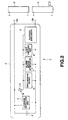
- Fig.2 is a block diagram showing a schematic structure of a battery pack.
- Fig.3 illustrates a schematic structure of a leakage detector.
- Figs.4a and 4b illustrate the structure of the leakage detector, Fig.4a being a plan view of a leakage detection unit and Fig.4b being a longitudinal cross-sectional view showing a modification of the leakage detector.
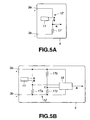
- Fig.5a is a circuit diagram showing a structure of a leakage detector and Fig.5b is a circuit diagram showing another structure of a leakage detector.
- Fig.6a is a circuit diagram showing a structure of a current breaker and Fig.6b is a circuit diagram showing another structure of a current breaker.
- Fig.7a is a circuit diagram showing a structure of a discharging device
- Fig.7b is a circuit diagram showing another structure of a discharging device
- Fig.7c is a circuit diagram showing yet another structure of a discharging device
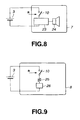
- Fig.8 is a circuit diagram showing a structure of an alarm sound generating device.
- Fig.9 is a circuit diagram showing a structure of a light emitting device.
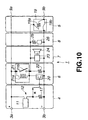
- Fig.10 is a circuit diagram showing a specified structure of a battery pack.
- the battery cell 3 used is a lithium ion secondary cell, only by way of an example.
- secondary batteries such as a nickel-cadmium cell, a nickel-hydrogen cell, a lithium ion cell, a lithium polymer cell or a lead cell, or primary batteries, such as a manganese battery, an alkali battery or a lithium battery, may also be used.
- the leakage detection unit 4 has the function of detecting possible leakage occurring in the battery cell 3 accommodated in the battery pack 1.
- the leakage detection unit 4 includes a leakage detector 11 and a leakage verification unit 12, as shown in Fig.3.
- the leakage detector 11 is provided with an electrically conductive metal line 11a and an insulating member 11b.
- the electrically conductive metal line 11a is of a pattern of two parallel interconnection lines electrically insulated from each other by the insulating member 11b.
- the leakage detector 11 should liquid leakage occur in the battery cell 3, such that the electrolyte solution is affixed across the two lines of the electrically conductive metal line 11a, the electrical resistance across the lines of the electrically conductive metal line 11a is lowered.
- One or more leakage detectors 11 are provided in the battery pack 1. Meanwhile, the leakage detector 11 is arranged in the vicinity of the positive electrode of each battery cell 3 because the leakage is most likely to occur in the area in the vicinity of the positive electrode of each battery cell 3.
- the leakage detector 11 is comprised of a pair of copper foil patterns 14, in the form of comb teeth each 20 mm long, formed on an insulating printed circuit board 13, these copper foil patterns 14 being arranged parallel and in a staggered relation to each other, with an interval of 1 mm therebetween.
- the copper foil patterns 14 are connected to each other by the electrolyte solution which has leaked and has become deposited thereon, so that the resistance value between the copper foil patterns 14 is decreased to complete an electrically conductive current line. If the voltage not lower than approximately IV is continuously applied across the copper foil patterns 14, migration occurs on deposition of the electrolyte solution across the copper foil patterns 14, thus shorting an area lying between the copper foil patterns 14.
- an insulating sheet may be bonded to each of the printed circuit board 13 and to the copper foil patterns 14 formed thereon. If the insulating sheets are bonded in this manner to the printed circuit board 13 and to the copper foil patterns 14, it is possible to provide for a wider leakage detection site to enable leakage detection over a wider area.
- the insulating sheet may be prepared of a combustion-retardant paper sheet exhibiting insulation and hygroscopic properties.
- the leakage detector 11 is comprised of two polymer tubes 15 sheathing copper wires 16, 16 affixed to each other such as by fusion, as shown in Fig.4b.
- the tubes 15 are formed of a material capable of absorbing the electrolyte solution, such as resin or polymer.
- the leakage detector 11 is constructed so that the tubes are rendered hygroscopic by having numerous pores to permit electrical conduction across the copper lines 16 by permeation of the deposited electrolyte solution on leakage, and so that, in the absence of deposited or permeated electrolyte solution, the tubes 15 act for insulating the space between the two copper lines 16.
- the leakage detector 11 is constructed so that the electrolyte solution deposited thereon is permeated into the tubes 15 to provide for electrically conduction between the two copper lines 16 to lower the resistance of the area confined between the copper lines to establish an electrically conductive electrical current path.
- the leakage verification unit 12 measures the resistance value across the electrically conductive metal lines 11a and compares the so-measured resistance value to a pre-set reference value to verify whether or not the leakage has occurred. Since the resistance value in the leakage detector 11 on occurrence of the leakage of the electrolyte solution and deposition thereof in the leakage detector 11 is less than 100 k ⁇ , the leakage verification unit 12 sets a reference value of the resistance across the two electrically conductive metal lines 11a to 100 k ⁇ , and verifies the occurrence of the leakage when the resistance value is less than 100 k ⁇ .
- the leakage verification unit 12 When the leakage verification unit 12 has verified that leakage has occurred in the battery cell 3, the unit 12 issues a leakage detection signal R.
- This leakage detection signal R is reflected in the operations of the current breaker 5, discharging device 6, alarm sound generating device 7 and the light emitting device 8, as will be explained in detail subsequently.
- an end of one of the electrically conductive metal lines 11a of the leakage detector 11 is connected to a point A, connected in turn to the positive electrode 3a of the battery cell 3, whilst an end of the other electrically conductive metal line 11a is connected to a point B, connected in turn to a negative electrode 3b of the battery cell 3 through a resistor 17a of approximately 100 k ⁇ , as shown for example in Fig.5a.
- the leakage verification unit 12 verifies that the leakage has occurred, and accordingly outputs a leakage detection signal R.
- one end of the electrically conductive metal line 11a is connected to the point A, connected in turn to the positive electrode 3a of the battery cell 3, and the end of the other electrically conductive metal line 11a is connected to the negative electrode 3b of the battery cell 3 through a resistor 17a (100 k ⁇ ), while a voltage comparator 18 is connected to the battery cell 3, as shown in Fig.5b.
- the voltage at the point B is inputted as a detection voltage input to the voltage comparator 18, whilst two serially connected resistors 17b, 17c are connected in parallel across the positive electrode 3a and the negative electrode 3b of the battery cell 3, with the voltage at a point C, as a median point of the two resistors 17b, 17c, being inputted as a reference voltage input to the voltage comparator 18.
- the resistance values of the resistors 17b, 17c are equal to each other, with the voltage at the point C' as a reference voltage input point being one- half the voltage of the battery cell 3.
- the current breaker 5, shown in Fig.6b includes a field-effect transistor 20, in place of the switch 10 shown in Fig.6b.
- the fuse provided with a heater 19 is connected through this field-effect transistor 20 to the battery cell 3.
- the field-effect transistor 20 a N-channel field-effect transistor, for example, is used.
- the gate-to-source voltage of the field-effect transistor 20 is approximately 4V,by the leakage detection signal R from the leakage detection unit 4, with the drain- to-source resistance becoming sufficiently low.
- the voltage of approximately 4 V of the battery cell 3 is applied to the heater resistance 19b of the fuse provided with a heater 19, thus heating the heater resistance 19b.
- the temperature fuse 19a interconnecting the battery cell 3 mounted near-by and the external terminal 9a, is broken under the heat generated by the heater resistance 19b.
- the discharging device 6 plays the role of self-discharging the battery cell 3 in which the leakage has occurred.
- a resistor, a temperature detecting posister or a polyswitch (PTC) is connected to the battery cell 3 to cause self-discharge of the battery cell 3 until its voltage is reduced to 0 V.
- the resistor of the discharging device 6 is set to a resistance value which will give a sufficiently small discharge current value in order to prevent the temperature of the battery pack 1 from increasing excessively on self-discharging.
- the resistance value of the resistor connected to the battery cell 3 and the resistance value of the temperature detecting posister are set to 1 k ⁇ and to 470 ⁇ , respectively.
- the PTC has the function of limiting the current value so that the self-temperature will be not higher than approximately 120°C, and hence there is no possibility of the temperature becoming excessively high. Therefore, the PTC is set to a resistance value of 100 k ⁇ .
- temperature rise in the battery pack 1 undergoing self- discharging at the resistor etc is not higher than approximately 5°C, which is a sufficiently safe temperature with no risk of e.g., ignition.
- a resistor 22 is connected via an electro-magnetic relay 21 to the battery cell 3, whilst a field effect transistor 20 is connected via the electro-magnetic relay 21 to the battery cell 3.
- the electro-magnetic relay 21 is a non-restoration type switching element comprised of a set coil 21a and a contact output 21b.
- a switch 10 shown in Fig.7b, or a field effect transistor 10, shown in Fig.7c may also be used in place of the electro-magnetic relay 21 controlling the state of connection across the resistor 22 and the battery cell 3.
- the discharging device 6 starts to be discharged by a resistor. After lapse of a certain time, the voltage of the battery cell 3 is 0V to complete the discharging.
- the alarm sound generating device 7 and the light emitting device 8 operate as alarming means for a user of the battery pack 1, and perform the role of communicating the fact of leakage to outside.
- the alarm sound generating device 7 and the light emitting device 8 are connected in series with the battery cell 3 via switch 10.
- the alarm sound generating device 7 issues an alarm tone by the leakage detection signal from the leakage detection unit 4 to communicate the fact of leakage to outside, specifically to a user of the battery pack 1 by the alarm sound.
- the light emitting device 8 lights a lamp etc by the leakage detection signal from the leakage detection unit 4 to communicate the fact of leakage to outside, specifically to a user of the battery pack 1 by light.
- a display which reads: "if the alarm sound is issued, the battery pack is malfunctioning, so please stop using the battery pack” is provided on a caution label of the battery pack 1 by way of prompting the user to discontinue the use of the battery pack.
- an alarm sound generator 23 and a speaker 24 are connected to the battery cell 3 through a switch 10, as shown for example in Fig.8.
- a resistor 25 and a light emitting diode 26 are connected through the switch 10 to the battery cell 3, as shown for example in Fig.9.
- the battery pack 1 detects the leakage occurring in the battery cell 3 by the above-mentioned leakage detection unit 4.
- the battery cell 3 suffering the leakage is electrically disconnected from outside to render the charging/discharging impossible to stop the progress of the malfunctioning caused by leakage to prohibit occurrence of accidents such as ignition or fuming.
- the user since the occurrence of unusual states is communicated to a user by the alarm sound from the alarm sound generating device 7 or light emitted by the light emitting device 8 , the user is able to recognize the unusual state in the battery pack to take proper steps such as stopping using the battery pack to prohibit unusual heating and occurrence of accidents such as ignition or fuming ascribable to such heating.
- the leakage detection unit 4 If, in the battery pack 1, no leakage of the electrolyte solution is occurring in the battery cell 3, no leakage of the electrolyte solution is detected by the leakage detection unit 4, so that the leakage detection signal R is not outputted to the switch 10. Therefore, the switch 10 in the battery pack 1 is kept in its off state, so that none of the current breaker 5, discharging device 6, alarm sound generating device 7 and the light emitting device 8 is connected to the battery cell 3 and hence is not in operation. That is, the battery pack 1 is maintained in a state of charging or discharging the battery cell 2 enclosed in the battery pack 1.
- the leakage detection unit 4 If conversely the leakage of the electrolyte solution has occurred in the battery cell 3 inside the battery pack 1, such leakage of the electrolyte solution is detected by the leakage detection unit 4, so that the leakage detection signal R is outputted to the switch 10.
- the switch 10 In the battery pack 1, the switch 10 is switched from its off state to its on state, by this leakage detection signal R, so that the current breaker 5, discharging device 6, alarm sound generating device 7 and the light emitting device are connected to the battery cell 3 to perform the following operations:
- the current breaker 5 interrupts the current line across the battery cell 3 and the external terminal 9b to disable the charging or discharging of the battery pack 1.
- the discharging device 6 discharges the battery cell 3 until the voltage of the battery cell 3 is 0 V.
- the alarm sound generating device 7 also advises the unusual state of the battery cell 3 in the battery pack 1, specifically, the occurrence of leakage, by issuing an alarm sound, such as by a buzzer.
- the light emitting device 8 issues the light that can be recognized from outside, such as light from a lamp, thus advising the user of the occurrence of leakage of the electrolyte solution in the battery cell 3 in the battery pack 1.
- the battery pack 1 shown in Fig.10, is made up of the leakage detection unit 4, current breaker 5, discharging device 6, alarm sound generating device 7 and the light emitting device 8, shown in Figs.5a, 6a, 7a, 8 and 9, respectively.
- the resistance across the electrically conductive metal lines. 11a is not less than 10 M ⁇ , with the voltage at a point B being 0 V, such that the leakage detection signal R is not issued.
- the gate voltage of the field effect transistor 20 is 0 V, with the resistance across the source and the drain of the field effect transistor 20 being not less than approximately 1 M ⁇ . Therefore, no current flows through the set coil 21a of the electro-magnetic relay 21, and hence the contact output 21b of the electro-magnetic relay 21 is kept in its off state, so that none of the current breaker 5, discharging device 6, alarm sound generating device 7 and the light emitting device 8 is connected to the battery cell 3. So, none of these components is in operation.
- the resistance value across the electrically conductive metal lines 11a is as low as approximately 100 k ⁇ or less, as a result of deposition of the electrolyte solution, so that a leakage detection signal R is issued.
- the magnitude of the output leakage detection signal R is not less than approximately 2V when the voltage at the point B is not less than one-half the voltage of the battery cell 3, for example, when the voltage of the battery cell 3 is approximately 4V.
- the gate voltage of the field effect transistor 20 is not less than approximately 2V, with the source-to-drain voltage of the field effect transistor 20 being 0 ⁇ .
- the voltage of approximately 4V of the battery cell 3 is applied to the heater resistor 19a of the fuse provided with a heater 19. If the resistance value of the heater resistor 19a is approximately 4 ⁇ and the fusing temperature of the temperature fuse 19b is approximately 230°C, the voltage of approximately 4V of the battery cell 3 is applied to the heater resistor 19a. The current of approximately 1A flows through the heater resistor 19a to evolve the heat of approximately 4W. By this heating of the heater resistor 19a, the temperature fuse 19b is located. When the temperature of the temperature fuse 19b is not lower than approximately 230°C, the temperature fuse 19b is fused.
- the current line between the battery cell 3 and the external terminals 9 specifically, the current line between the negative electrode 3b of the battery cell 3 and the external terminal 9b, that is between the negative electrode 3b of the battery cell 3 and the external terminal 9b of the negative electrode, is interrupted to disable the charging from the charger Y and the discharging to the main equipment body unit X.
- the gate voltage of the field effect transistor 20 is approximately not lower than approximately 2V, with its drain-to-source resistance being 0 ⁇ .
- the voltage of approximately 4V is applied to the set coil 21a to switch the contact output 21b from the off state to the on-state.
- the contact output 21b switched to the on state, the voltage is applied to the resistor 22, so that the current of approximately 4 mA flows through the resistor 22.
- the current of approximately 4 mA continues to flow through the resistor 22 until the voltage of the battery cell is equal to 0 V, to effect discharging.
- the voltage of the battery cell 3 is 800 mAH
- the voltage of the battery cell 3 is 0 V after discharging for approximately 200 hours, with the battery pack 1 then being in a safe state, that is, the electrical energy in the battery pack 1 is reduced to zero.
- the voltage When the voltage is applied to the alarm sound generating device 7, the latter issues an alarm sound signal at a speaker, to advise the user of the occurrence of an unusual state.
- the voltage of approximately 4V is applied to the resistor and to the LED. If the resistance value of the resistor is 100 ⁇ , approximately 2V is applied to the resistor, with the voltage of 2V being applied to the LED through which flows the current. The LED emits light, since the current of 20 mA flows therein, to advise the user of the occurrence of troubles.
- the battery pack I is provided with the current breaker 5, discharging device 6, alarm sound generating device 7 and the light emitting device 8, the present invention is not limited to this merely illustrative configuration. It is only sufficient if, in the battery pack 1, the leakage of the battery cell 3 is detected and, if such leakage occurs, the electrical connection across the battery cell 3 and the external terminals 9 is interrupted by the leakage detection unit 4 and the current breaker 5.
- leakage in the battery cell 3 is detected by changes in the resistance value of the leakage detector 11.
- the arrangement may also be made so that heating of the battery cell 3 is monitored, a leakage detection signal R is issued on detection of unusual heating to electrically interrupt the current line between the battery cell 3 and the external terminals 9 to effect self-discharging of the discharging device 6.
Abstract
Description
- This invention relates to a battery pack having one or more battery cells enclosed therein. More particularly, it relates to a battery pack in which, on occurrence of liquid leakage in an internal battery cell, such liquid leakage is detected to prohibit the progression of malfunctions caused by such liquid leakage.
- The battery pack, used as a driving power source for a portable electrical equipment, such as a personal computer, portable telephone or a video camera, referred to below simply as a main equipment, includes one or more battery cells and a control circuit, in its inside, these battery cells and the control circuit being interconnected by a complex interconnection.
- In these battery packs, leakage of the electrolyte solution, sealed in the battery cell, is likely to occur if a shock is applied from outside to the battery pack due to fall or collision, if the exterior of the battery cell is rusted due to moisture intruded into the inside of the battery pack, or if the junction of the exterior in the vicinity of the positive electrode of the battery cell is deteriorated or punched. If such leakage of the electrolyte solution occurs in one of the battery cells in the battery pack, the electrolyte solution flows into and is spread in the inside of the battery pack to become attached to the interconnection or to a substrate of the control circuit. In the battery pack, the electrolyte solution tends to become attached to the interconnection or to a substrate of the control circuit and, after lapse of a certain time interval, metals such as copper, iron, aluminum or nickel of the interconnection or the substrate are dissolved into the electrolyte solution. In such case, the resistance of the portion to which the electrolyte solution has attached is lowered to form a new electrically conductive line of a certain resistance value. The resistance of the portions to which the electrolyte solution has attached may, for example, be on the order of 1 to 10 Ω. There are occasions where the electrically conductive line produced by leakage of the electrolyte solution is connected to both the positive and negative electrodes.
- If the above-mentioned electrically conductive line has interconnected the positive and negative electrodes of the battery cell, the voltage of the battery cell is applied to the electrically conductive line so that the current flows therein to evolve heat to raise the cell temperature. For example, if the voltage of the battery cell is 4V and the resistance of the electrically conductive is 1 Ω, the current of 1A flows in the electrically conductive line to evolve the heat of 4W. If, in the battery pack, the temperature of the electrically conductive line is raised gradually to reach 200°C or higher, accidents due to leakage of the electrolyte solution, such as filming or firing, occur in the electrically conductive line.
- Moreover, the heat of the electrically conductive line is transmitted to the battery cell arranged in its vicinity, such that the risk of fuming or firing occurs even in the battery cell the terminals of which are not interconnected by the electrically conductive line. For example, if the heat evolved in the electrically conductive line is transmitted such that the temperature in the battery cell exceeds 130°C, the synthetic resin separator isolating the positive and negative electrodes from each other in the battery cell is dissolved to short the positive and negative electrodes to cause internal shorting to evolve heat and consequent fuming or firing thus leading to accidents ascribable to leakage.
- With the conventional battery pack, there are lacking sufficient countermeasures against occurrence of accidents ascribable to the above-described leakage of electrolyte solutions. Thus, in a certain conventional battery pack, insulating paper sheets capable of absorbing the electrolyte solution are placed about the battery cell to absorb the electrolyte solution to prevent an electrically conductive line from being formed on occurrence of leakage. In another conventional battery pack, metallic portions of the interconnection or the substrate are coated with an adhesive or a synthetic resin to prevent the metal from being dissolved in the electrolyte solution to prevent an electrically conductive line from being formed on occurrence of leakage.
- However, if the insulating paper sheet is used, it is difficult to absorb the leaked electrolyte solution completely. On the other hand, if the metal portions are coated with e.g., an adhesive, such a phenomenon occurs in which the adhesive is first dissolved in the electrolyte solution before the metal portions are dissolved.
- In addition, if, in the interior of the battery pack, leakage of the electrolyte solution has occurred, a user can hardly recognize the unusual occurrence, such that there is a risk of charging/discharging being repeated as the leaked state is not remedied. If the charging/discharging is repeated after the occurrence of the leakage of the electrolyte solution, the battery pack tends to fall into disorder, that is the leakage of the electrolyte solution and the dissolution of metal are allowed to progress, so that a dangerous state is apt to be produced.
- It is therefore an object of the present invention to provide a battery pack in which, if leakage of the electrolyte solution occurs in the battery pack, the progress of the trouble of the battery cell or the battery pack due to the leakage of the electrolyte solution is prohibited to prevent occurrence of accidents.
- In accordance with the present invention, there is provided a battery pack including a battery cell, leakage detection means for detecting the leakage of an electrolyte solution of the battery cell, current breaking means for electrically interrupting the current line between the battery cell and external terminals on occurrence of leakage of the electrolyte solution in the battery cell and discharging means having the function of self-discharging the battery cell.
- In the above-described battery pack according to the present invention, if leakage occurs in an internal battery cell, it is detected by leakage detection means, and the current line between the battery cell and the external terminals is electrically interrupted by the current breaking means, so that the battery cell is self-discharged by discharging means until the voltage of the battery cell is reduced to zero. That is, should leakage occur, the electronic energy in the battery pack ultimately becomes equal to zero. So, in the present battery pack, charging/discharging is disabled on occurence of leakage of the electrolyte solution to stop the progress of the malfunctions ascribable to such leakage to prevent accidents, such as heating, fuming or ignition from occurrence.
- That is, in the battery pack according to the present invention, there is provided a function of disconnecting the connection line between the external terminals and the battery cell on detection of leakage of the electrolyte solution, so that the battery pack in the unusual state is necessarily unusable to prevent the accident due to the leakage from progressing to prevent unusual heating and accidents of ignition or fuming ascribable to such heating.
- Fig. 1 illustrates a schematic structure of a battery pack.
- Fig.2 is a block diagram showing a schematic structure of a battery pack.
- Fig.3 illustrates a schematic structure of a leakage detector.
- Figs.4a and 4b illustrate the structure of the leakage detector, Fig.4a being a plan view of a leakage detection unit and Fig.4b being a longitudinal cross-sectional view showing a modification of the leakage detector.
- Fig.5a is a circuit diagram showing a structure of a leakage detector and Fig.5b is a circuit diagram showing another structure of a leakage detector.
- Fig.6a is a circuit diagram showing a structure of a current breaker and Fig.6b is a circuit diagram showing another structure of a current breaker.
- Fig.7a is a circuit diagram showing a structure of a discharging device, Fig.7b is a circuit diagram showing another structure of a discharging device and Fig.7c is a circuit diagram showing yet another structure of a discharging device
- Fig.8 is a circuit diagram showing a structure of an alarm sound generating device.
- Fig.9 is a circuit diagram showing a structure of a light emitting device.
- Fig.10 is a circuit diagram showing a specified structure of a battery pack.
- Referring to the drawings, preferred embodiments of a battery pack according to the present invention will be explained in detail. A
battery pack 1 according to the present invention includes one ormore battery cells 3, for example, twobattery cells 3, aleakage detection unit 4, acurrent breaker 5, adischarging device 6, an alarmsound generating device 7 and alight emitting device 8, within anexternal casing 2, as shown in Fig.1. Thebattery pack 1 is provided with external terminals 9 (apositive electrode terminal 9a and anegative electrode terminal 9b), by means of which thebattery pack 1 is connected to a main equipment body unit X, and a charger Y, both lying outside theexternal casing 2, as shown in Figs.1 and 2. The main equipment body unit X has thebattery pack 1 as a driving power source, whilst the charger Y is used for charging thebattery pack 1. Theexternal terminals 9 are electrically connected to thebattery cell 3 provided in theexternal casing 2. - The
battery cell 3 used is a lithium ion secondary cell, only by way of an example. Thus, secondary batteries, such as a nickel-cadmium cell, a nickel-hydrogen cell, a lithium ion cell, a lithium polymer cell or a lead cell, or primary batteries, such as a manganese battery, an alkali battery or a lithium battery, may also be used. - The
leakage detection unit 4 has the function of detecting possible leakage occurring in thebattery cell 3 accommodated in thebattery pack 1. Theleakage detection unit 4 includes aleakage detector 11 and aleakage verification unit 12, as shown in Fig.3. - The
leakage detector 11 is provided with an electricallyconductive metal line 11a and aninsulating member 11b. The electricallyconductive metal line 11a is of a pattern of two parallel interconnection lines electrically insulated from each other by theinsulating member 11b. In theleakage detector 11, should liquid leakage occur in thebattery cell 3, such that the electrolyte solution is affixed across the two lines of the electricallyconductive metal line 11a, the electrical resistance across the lines of the electricallyconductive metal line 11a is lowered. - One or
more leakage detectors 11 are provided in thebattery pack 1. Meanwhile, theleakage detector 11 is arranged in the vicinity of the positive electrode of eachbattery cell 3 because the leakage is most likely to occur in the area in the vicinity of the positive electrode of eachbattery cell 3. - The
leakage detector 11 is comprised of a pair ofcopper foil patterns 14, in the form of comb teeth each 20 mm long, formed on an insulating printedcircuit board 13, thesecopper foil patterns 14 being arranged parallel and in a staggered relation to each other, with an interval of 1 mm therebetween. In theleakage detector 11, thecopper foil patterns 14 are connected to each other by the electrolyte solution which has leaked and has become deposited thereon, so that the resistance value between thecopper foil patterns 14 is decreased to complete an electrically conductive current line. If the voltage not lower than approximately IV is continuously applied across thecopper foil patterns 14, migration occurs on deposition of the electrolyte solution across thecopper foil patterns 14, thus shorting an area lying between thecopper foil patterns 14. In theleakage detector 11, an insulating sheet, not shown, may be bonded to each of the printedcircuit board 13 and to thecopper foil patterns 14 formed thereon. If the insulating sheets are bonded in this manner to the printedcircuit board 13 and to thecopper foil patterns 14, it is possible to provide for a wider leakage detection site to enable leakage detection over a wider area. The insulating sheet may be prepared of a combustion-retardant paper sheet exhibiting insulation and hygroscopic properties. - The
leakage detector 11 is comprised of twopolymer tubes 15 sheathingcopper wires tubes 15 are formed of a material capable of absorbing the electrolyte solution, such as resin or polymer. Theleakage detector 11 is constructed so that the tubes are rendered hygroscopic by having numerous pores to permit electrical conduction across thecopper lines 16 by permeation of the deposited electrolyte solution on leakage, and so that, in the absence of deposited or permeated electrolyte solution, thetubes 15 act for insulating the space between the twocopper lines 16. That is, theleakage detector 11 is constructed so that the electrolyte solution deposited thereon is permeated into thetubes 15 to provide for electrically conduction between the twocopper lines 16 to lower the resistance of the area confined between the copper lines to establish an electrically conductive electrical current path. - To the
leakage verification unit 12 are connected one ends of the two electricallyconductive metal lines 11a of theleakage detector 11, as shown in Fig.3. Theleakage verification unit 12 measures the resistance value across the electricallyconductive metal lines 11a and compares the so-measured resistance value to a pre-set reference value to verify whether or not the leakage has occurred. Since the resistance value in theleakage detector 11 on occurrence of the leakage of the electrolyte solution and deposition thereof in theleakage detector 11 is less than 100 kΩ, theleakage verification unit 12 sets a reference value of the resistance across the two electricallyconductive metal lines 11a to 100 kΩ, and verifies the occurrence of the leakage when the resistance value is less than 100 kΩ. When theleakage verification unit 12 has verified that leakage has occurred in thebattery cell 3, theunit 12 issues a leakage detection signal R. This leakage detection signal R is reflected in the operations of thecurrent breaker 5, dischargingdevice 6, alarmsound generating device 7 and thelight emitting device 8, as will be explained in detail subsequently. - In the above-described
leakage verification unit 12, an end of one of the electricallyconductive metal lines 11a of theleakage detector 11 is connected to a point A, connected in turn to thepositive electrode 3a of thebattery cell 3, whilst an end of the other electricallyconductive metal line 11a is connected to a point B, connected in turn to anegative electrode 3b of thebattery cell 3 through aresistor 17a of approximately 100 kΩ, as shown for example in Fig.5a. When the voltage of the point B, to which is connected the end of theother metal line 11a, is not lower than one-half the voltage of thebattery cell 3, such as not lower than approximately 2V, which is one-half the voltage of 4V of thebattery cell 3, theleakage verification unit 12 verifies that the leakage has occurred, and accordingly outputs a leakage detection signal R. - In the
leakage verification unit 12, one end of the electricallyconductive metal line 11a is connected to the point A, connected in turn to thepositive electrode 3a of thebattery cell 3, and the end of the other electricallyconductive metal line 11a is connected to thenegative electrode 3b of thebattery cell 3 through aresistor 17a (100 kΩ), while avoltage comparator 18 is connected to thebattery cell 3, as shown in Fig.5b. In thisleakage verification unit 12, the voltage at the point B is inputted as a detection voltage input to thevoltage comparator 18, whilst two serially connectedresistors positive electrode 3a and thenegative electrode 3b of thebattery cell 3, with the voltage at a point C, as a median point of the tworesistors voltage comparator 18. The resistance values of theresistors battery cell 3. When the voltage detection input at thevoltage comparator 18 is not less than the voltage value of the reference input voltage, theleakage verification unit 12 verifies that the leakage has occurred, and outputs the leakage detection signal R. - Meanwhile, the leakage detection signal R in the
leakage verification unit 12 of theleakage detection unit 4 may be outputted to each of thecurrent breaker 5, dischargingdevice 6, alarmsound generating device 7 and to thelight emitting device 8. The leakage detection signal R may also be outputted to aswitch 10 which controls the connecting state to thebattery cell 3 of thecurrent breaker 5, dischargingdevice 6, alarmsound generating device 7 and thelight emitting device 8, as shown in Fig.2. Theswitch 10 has its contact switched from the released state to the connected state by the leakage detection signal R outputted by theleakage detection unit 4. As theswitch 10, a latching type electro-magnetic relay or a single stable type electro- magnetic relay is used. - The
current breaker 5 plays the function of electrically disconnecting thebattery cell 3, suffering the leakage, form theexternal terminals 9. Thecurrent breaker 5 breaks the current line for charging and discharging between thebattery cell 3 and theexternal terminals 9 by the leakage detection signal R outputted by theleakage verification unit 12 of theleakage detection unit 4. As thecurrent breaker 5, an SC protector having a temperature fuse and a heater, a field-effect transistor or a transistor may be used. - In the
current breaker 5, a fuse provided with aheater 19 is connected through theswitch 10 to thebattery cell 3, as shown in Fig.6a. The fuse provided with aheater 19 is provided with atemperature fuse 19a, completing a current line between thebattery cell 3 and theexternal terminal 9b, and with aheater resistance 19b connected to thebattery cell 3 through theswitch 10. In thecurrent breaker 5, if theswitch 10 is closed by the leakage detection signal R from theleakage detection unit 4, the voltage of thebattery cell 3 is applied to theheater resistance 19b of the fuse provided with aheater 19. In thecurrent breaker 5, theheater resistance 19b, to which is applied the voltage of thebattery cell 3, evolves heat which melts thetemperature fuse 19a interconnecting thebattery cell 3 mounted near-by and theexternal terminal 9b. - The
current breaker 5, shown in Fig.6b, includes a field-effect transistor 20, in place of theswitch 10 shown in Fig.6b. The fuse provided with aheater 19 is connected through this field-effect transistor 20 to thebattery cell 3. As the field-effect transistor 20, a N-channel field-effect transistor, for example, is used. In thiscurrent breaker 5, the gate-to-source voltage of the field-effect transistor 20 is approximately 4V,by the leakage detection signal R from theleakage detection unit 4, with the drain- to-source resistance becoming sufficiently low. In thecurrent breaker 5, the voltage of approximately 4 V of thebattery cell 3 is applied to theheater resistance 19b of the fuse provided with aheater 19, thus heating theheater resistance 19b. In thecurrent breaker 5, thetemperature fuse 19a, interconnecting thebattery cell 3 mounted near-by and theexternal terminal 9a, is broken under the heat generated by theheater resistance 19b. - The discharging
device 6 plays the role of self-discharging thebattery cell 3 in which the leakage has occurred. By the leakage detection signal, outputted by theleakage detection unit 4, a resistor, a temperature detecting posister or a polyswitch (PTC) is connected to thebattery cell 3 to cause self-discharge of thebattery cell 3 until its voltage is reduced to 0 V. At this time, the resistor of the dischargingdevice 6 is set to a resistance value which will give a sufficiently small discharge current value in order to prevent the temperature of thebattery pack 1 from increasing excessively on self-discharging. In the dischargingdevice 6, the resistance value of the resistor connected to thebattery cell 3 and the resistance value of the temperature detecting posister are set to 1 kΩ and to 470 Ω, respectively. For example, the PTC has the function of limiting the current value so that the self-temperature will be not higher than approximately 120°C, and hence there is no possibility of the temperature becoming excessively high. Therefore, the PTC is set to a resistance value of 100 kΩ. In the dischargingdevice 6, temperature rise in thebattery pack 1 undergoing self- discharging at the resistor etc is not higher than approximately 5°C, which is a sufficiently safe temperature with no risk of e.g., ignition. - In the discharging
device 6, aresistor 22 is connected via an electro-magnetic relay 21 to thebattery cell 3, whilst afield effect transistor 20 is connected via the electro-magnetic relay 21 to thebattery cell 3. The electro-magnetic relay 21 is a non-restoration type switching element comprised of aset coil 21a and acontact output 21b. In the dischargingdevice 6, if, on reception of the leakage detection signal R from theleakage detection unit 4, the drain-to-source resistance of thefield effect transistor 20 becomes sufficiently small, the battery cell voltage is applied to theset coil 21a, and thecontact output 21b of the electro-magnetic relay 21 is switched to the connected state, the current of thebattery cell 3 flows to theresistor 22 by way of discharging. - In the discharging
device 6, aswitch 10, shown in Fig.7b, or afield effect transistor 10, shown in Fig.7c, may also be used in place of the electro-magnetic relay 21 controlling the state of connection across theresistor 22 and thebattery cell 3. - Directly after occurrence of leakage, the discharging
device 6 starts to be discharged by a resistor. After lapse of a certain time, the voltage of thebattery cell 3 is 0V to complete the discharging. - The alarm
sound generating device 7 and thelight emitting device 8 operate as alarming means for a user of thebattery pack 1, and perform the role of communicating the fact of leakage to outside. Similarly to thecurrent breaker 5 and the dischargingdevice 6, the alarmsound generating device 7 and thelight emitting device 8 are connected in series with thebattery cell 3 viaswitch 10. The alarmsound generating device 7 issues an alarm tone by the leakage detection signal from theleakage detection unit 4 to communicate the fact of leakage to outside, specifically to a user of thebattery pack 1 by the alarm sound. Thelight emitting device 8 lights a lamp etc by the leakage detection signal from theleakage detection unit 4 to communicate the fact of leakage to outside, specifically to a user of thebattery pack 1 by light. Preferably, a display which reads: "if the alarm sound is issued, the battery pack is malfunctioning, so please stop using the battery pack" is provided on a caution label of thebattery pack 1 by way of prompting the user to discontinue the use of the battery pack. - In the alarm
sound generating device 7, analarm sound generator 23 and aspeaker 24 are connected to thebattery cell 3 through aswitch 10, as shown for example in Fig.8. In thelight emitting device 8, aresistor 25 and alight emitting diode 26 are connected through theswitch 10 to thebattery cell 3, as shown for example in Fig.9. - The
battery pack 1 detects the leakage occurring in thebattery cell 3 by the above-mentionedleakage detection unit 4. In addition, thebattery cell 3 suffering the leakage is electrically disconnected from outside to render the charging/discharging impossible to stop the progress of the malfunctioning caused by leakage to prohibit occurrence of accidents such as ignition or fuming. - In the
battery pack 1, since discharging occurs in the dischargingdevice 6, directly after occurrence of leakage, until the voltage of thebattery cell 3 is zero, no current flows through the electrically conductive line produced due to the leaking electrolyte solution, thus prohibiting unusual heating and occurrence of accidents such as ignition or fuming ascribable to such heating. - Moreover, in the
battery pack 1, since the occurrence of unusual states is communicated to a user by the alarm sound from the alarmsound generating device 7 or light emitted by thelight emitting device 8 , the user is able to recognize the unusual state in the battery pack to take proper steps such as stopping using the battery pack to prohibit unusual heating and occurrence of accidents such as ignition or fuming ascribable to such heating. - Referring first to Fig.2, the operation of the
battery pack 1, constructed as described above, is explained in detail. - If, in the
battery pack 1, no leakage of the electrolyte solution is occurring in thebattery cell 3, no leakage of the electrolyte solution is detected by theleakage detection unit 4, so that the leakage detection signal R is not outputted to theswitch 10. Therefore, theswitch 10 in thebattery pack 1 is kept in its off state, so that none of thecurrent breaker 5, dischargingdevice 6, alarmsound generating device 7 and thelight emitting device 8 is connected to thebattery cell 3 and hence is not in operation. That is, thebattery pack 1 is maintained in a state of charging or discharging thebattery cell 2 enclosed in thebattery pack 1. - If conversely the leakage of the electrolyte solution has occurred in the
battery cell 3 inside thebattery pack 1, such leakage of the electrolyte solution is detected by theleakage detection unit 4, so that the leakage detection signal R is outputted to theswitch 10. In thebattery pack 1, theswitch 10 is switched from its off state to its on state, by this leakage detection signal R, so that thecurrent breaker 5, dischargingdevice 6, alarmsound generating device 7 and the light emitting device are connected to thebattery cell 3 to perform the following operations: - That is, the
current breaker 5 interrupts the current line across thebattery cell 3 and theexternal terminal 9b to disable the charging or discharging of thebattery pack 1. On the other hand, the dischargingdevice 6 discharges thebattery cell 3 until the voltage of thebattery cell 3 is 0 V. The alarmsound generating device 7 also advises the unusual state of thebattery cell 3 in thebattery pack 1, specifically, the occurrence of leakage, by issuing an alarm sound, such as by a buzzer. Moreover, thelight emitting device 8 issues the light that can be recognized from outside, such as light from a lamp, thus advising the user of the occurrence of leakage of the electrolyte solution in thebattery cell 3 in thebattery pack 1. - The specified operation of the above-described
battery pack 1 is now explained with reference to Fig. 10. Meanwhile, thebattery pack 1, shown in Fig.10, is made up of theleakage detection unit 4,current breaker 5, dischargingdevice 6, alarmsound generating device 7 and thelight emitting device 8, shown in Figs.5a, 6a, 7a, 8 and 9, respectively. - If, in the
battery pack 1, no leakage of the electrolyte solution is occurring in thebattery cell 3, the resistance across the electrically conductive metal lines. 11a is not less than 10 MΩ, with the voltage at a point B being 0 V, such that the leakage detection signal R is not issued. At this time, the gate voltage of thefield effect transistor 20 is 0 V, with the resistance across the source and the drain of thefield effect transistor 20 being not less than approximately 1 MΩ. Therefore, no current flows through theset coil 21a of the electro-magnetic relay 21, and hence thecontact output 21b of the electro-magnetic relay 21 is kept in its off state, so that none of thecurrent breaker 5, dischargingdevice 6, alarmsound generating device 7 and thelight emitting device 8 is connected to thebattery cell 3. So, none of these components is in operation. - If conversely the leakage of the electrolyte solution has occurred in the
battery cell 3, the resistance value across the electricallyconductive metal lines 11a is as low as approximately 100 kΩ or less, as a result of deposition of the electrolyte solution, so that a leakage detection signal R is issued. The magnitude of the output leakage detection signal R is not less than approximately 2V when the voltage at the point B is not less than one-half the voltage of thebattery cell 3, for example, when the voltage of thebattery cell 3 is approximately 4V. At this time, the gate voltage of thefield effect transistor 20 is not less than approximately 2V, with the source-to-drain voltage of thefield effect transistor 20 being 0 Ω. At this time, approximately 4V is applied to theset coil 21a of the electro-magnetic relay 21 of thebattery pack 1, such that thecontact output 21b is switched from the off state to the on state to connect thecurrent breaker 5, dischargingdevice 6, alarmsound generating device 7 and thelight emitting device 8 to thebattery cell 3 to perform the following operations: - That is, in the
current breaker 5, the voltage of approximately 4V of thebattery cell 3 is applied to theheater resistor 19a of the fuse provided with aheater 19. If the resistance value of theheater resistor 19a is approximately 4 Ω and the fusing temperature of thetemperature fuse 19b is approximately 230°C, the voltage of approximately 4V of thebattery cell 3 is applied to theheater resistor 19a. The current of approximately 1A flows through theheater resistor 19a to evolve the heat of approximately 4W. By this heating of theheater resistor 19a, thetemperature fuse 19b is located. When the temperature of thetemperature fuse 19b is not lower than approximately 230°C, thetemperature fuse 19b is fused. When thetemperature fuse 19b is fused, the current line between thebattery cell 3 and theexternal terminals 9, specifically, the current line between thenegative electrode 3b of thebattery cell 3 and theexternal terminal 9b, that is between thenegative electrode 3b of thebattery cell 3 and theexternal terminal 9b of the negative electrode, is interrupted to disable the charging from the charger Y and the discharging to the main equipment body unit X. - If the leakage detection signal R is outputted, the gate voltage of the
field effect transistor 20 is approximately not lower than approximately 2V, with its drain-to-source resistance being 0 Ω. At this time, the voltage of approximately 4V is applied to theset coil 21a to switch thecontact output 21b from the off state to the on-state. With thecontact output 21b switched to the on state, the voltage is applied to theresistor 22, so that the current of approximately 4 mA flows through theresistor 22. The current of approximately 4 mA continues to flow through theresistor 22 until the voltage of the battery cell is equal to 0 V, to effect discharging. For example, if the voltage of thebattery cell 3 is 800 mAH, the voltage of thebattery cell 3 is 0 V after discharging for approximately 200 hours, with thebattery pack 1 then being in a safe state, that is, the electrical energy in thebattery pack 1 is reduced to zero. - When the voltage is applied to the alarm
sound generating device 7, the latter issues an alarm sound signal at a speaker, to advise the user of the occurrence of an unusual state. In thelight emitting device 8, the voltage of approximately 4V is applied to the resistor and to the LED. If the resistance value of the resistor is 100Ω, approximately 2V is applied to the resistor, with the voltage of 2V being applied to the LED through which flows the current. The LED emits light, since the current of 20 mA flows therein, to advise the user of the occurrence of troubles. - Although the battery pack I is provided with the
current breaker 5, dischargingdevice 6, alarmsound generating device 7 and thelight emitting device 8, the present invention is not limited to this merely illustrative configuration. It is only sufficient if, in thebattery pack 1, the leakage of thebattery cell 3 is detected and, if such leakage occurs, the electrical connection across thebattery cell 3 and theexternal terminals 9 is interrupted by theleakage detection unit 4 and thecurrent breaker 5. - In the above-described
battery pack 1, leakage in thebattery cell 3 is detected by changes in the resistance value of theleakage detector 11. However, the arrangement may also be made so that heating of thebattery cell 3 is monitored, a leakage detection signal R is issued on detection of unusual heating to electrically interrupt the current line between thebattery cell 3 and theexternal terminals 9 to effect self-discharging of the dischargingdevice 6.
Claims (5)
- A battery pack connected to a main equipment body unit (X) or to a charger (Y) to effect charging or discharging, said battery pack (1) comprising:a battery cell (3);leakage detection means (4) for detecting the leakage of an electrolyte solution of said battery cell (3); andcurrent breaking means (5) for electrically interrupting a current line between said battery cell (3) and external terminals (9a, 9b) on occurrence of leakage of the electrolyte solution in said battery cell (3).
- The battery pack according to claim 1
wherein
discharging means (6) having the function of self-discharging the battery cell (3) is connected to said battery cell (3). - The battery pack according to claim 1
wherein
there is connected to said battery cell (3) alarming means (7; 8) for communicating to outside the occurrence of leakage of the electrolyte solution in said battery cell (3). - The battery pack according to claim 3
wherein
said alarming means is an alarm sound emitting device (7) for emitting an alarm sound to outside. - The battery pack according to claim 3
wherein
said alarming means is a light emitting device (8) for emitting light to outside.
Applications Claiming Priority (2)
| Application Number | Priority Date | Filing Date | Title |
|---|---|---|---|
| JP25809499 | 1999-09-10 | ||
| JP25809499A JP4608711B2 (en) | 1999-09-10 | 1999-09-10 | Battery pack |
Publications (3)
| Publication Number | Publication Date |
|---|---|
| EP1083619A2 true EP1083619A2 (en) | 2001-03-14 |
| EP1083619A3 EP1083619A3 (en) | 2004-06-30 |
| EP1083619B1 EP1083619B1 (en) | 2006-11-02 |
Family
ID=17315436
Family Applications (1)
| Application Number | Title | Priority Date | Filing Date |
|---|---|---|---|
| EP00402494A Expired - Lifetime EP1083619B1 (en) | 1999-09-10 | 2000-09-11 | Battery pack |
Country Status (4)
| Country | Link |
|---|---|
| US (1) | US6337559B1 (en) |
| EP (1) | EP1083619B1 (en) |
| JP (1) | JP4608711B2 (en) |
| DE (1) | DE60031613T2 (en) |
Cited By (13)
| Publication number | Priority date | Publication date | Assignee | Title |
|---|---|---|---|---|
| GB2421369A (en) * | 2004-12-17 | 2006-06-21 | Hitachi Ltd | Battery housing having output terminals and an output breaker |
| WO2011072989A1 (en) * | 2009-12-18 | 2011-06-23 | Continental Automotive Gmbh | Energy storage arrangement |
| WO2011144300A1 (en) * | 2010-05-18 | 2011-11-24 | Zentrum für Sonnenenergie- und Wasserstoff-Forschung Baden-Württemberg Gemeinnützige Stiftung | System and method for safely discharging an energy store |
| WO2013149763A1 (en) * | 2012-04-04 | 2013-10-10 | Robert Bosch Gmbh | Battery cell for a vehicle having a device for decoupling and/or bypassing terminals of the battery cell |
| WO2013164149A1 (en) * | 2012-05-02 | 2013-11-07 | Robert Bosch Gmbh | Method and device for assessing the state of an electrochemical store and electrochemical storage system |
| DE102013206922A1 (en) * | 2013-04-17 | 2014-05-08 | Continental Automotive Gmbh | Battery system for use with measuring probe for detection of hydrofluoric acid, has measuring probe and collecting unit, which are arranged in housing, such that liquid absorbed in collecting unit comes into contact with probe |
| DE102013204540A1 (en) * | 2013-03-15 | 2014-09-18 | Robert Bosch Gmbh | Battery cell device with depth discharge safety function and method for monitoring a battery cell |
| DE102013204527A1 (en) * | 2013-03-15 | 2014-09-18 | Robert Bosch Gmbh | Battery cell device with lithium deposit safety function and method for monitoring a battery cell |
| DE102013204529A1 (en) * | 2013-03-15 | 2014-09-18 | Robert Bosch Gmbh | Battery cell device with overpressure safety function and method for monitoring a battery cell |
| DE102013204532A1 (en) * | 2013-03-15 | 2014-09-18 | Robert Bosch Gmbh | Battery cell device with overheating safety function and method for monitoring a battery cell |
| DE102013204537A1 (en) * | 2013-03-15 | 2014-10-02 | Robert Bosch Gmbh | Battery cell device with accident safety function and method for monitoring a battery cell |
| EP3834741A1 (en) * | 2019-12-10 | 2021-06-16 | Covidien LP | System and method for temporarily and permanently disabling electronics in a disposable surgical tool |
| EP3716352A4 (en) * | 2017-11-22 | 2021-09-01 | TDK Corporation | Battery pack |
Families Citing this family (34)
| Publication number | Priority date | Publication date | Assignee | Title |
|---|---|---|---|---|
| JP3212963B2 (en) * | 1999-03-16 | 2001-09-25 | 松下電器産業株式会社 | Secondary battery control circuit |
| US7140546B1 (en) * | 2002-12-12 | 2006-11-28 | Symbol Technologies, Inc. | Battery pack with integrated human interface devices |
| JP4517223B2 (en) * | 2004-03-31 | 2010-08-04 | オリジン電気株式会社 | LIQUID LEAK DETECTION DEVICE EQUIPPED WITH A STEEL TYPE SENSOR |
| JP2006101635A (en) * | 2004-09-29 | 2006-04-13 | Mitsumi Electric Co Ltd | Over-charge/discharge detection device, and over-charge/discharge detection circuit and semiconductor device |
| JP4778218B2 (en) * | 2004-10-19 | 2011-09-21 | Necエナジーデバイス株式会社 | Battery pack |
| TWI309716B (en) * | 2006-06-14 | 2009-05-11 | Chin Ho Wang | Electrolyte detecting device and energy storing device using the same |
| KR100770108B1 (en) * | 2005-12-29 | 2007-10-24 | 삼성에스디아이 주식회사 | Battery pack and its manufacturing method |
| JP5092268B2 (en) * | 2006-04-24 | 2012-12-05 | パナソニック株式会社 | Leak detection device for power system |
| US20100291427A1 (en) * | 2009-05-15 | 2010-11-18 | Sinoelectric Powertrain Corporation | Modular powertrain, systems, and methods |
| US20100291426A1 (en) * | 2009-05-15 | 2010-11-18 | Sinoelectric Powertrain Corporation | Flexible fusible link, systems, and methods |
| US20100291419A1 (en) * | 2009-05-15 | 2010-11-18 | Sinoelectric Powertrain Corporation | Battery pack heat exchanger, systems, and methods |
| US20100291418A1 (en) * | 2009-05-15 | 2010-11-18 | Sinoelectric Powertrain Corporation | Battery packs, systems, and methods |
| US8349477B2 (en) * | 2009-05-28 | 2013-01-08 | Deeya Energy, Inc. | Optical leak detection sensor |
| JP4696291B2 (en) * | 2009-06-04 | 2011-06-08 | 三菱自動車工業株式会社 | Secondary battery abnormality detection device |
| JP5414432B2 (en) * | 2009-09-09 | 2014-02-12 | 株式会社半導体エネルギー研究所 | Power storage system |
| KR101383599B1 (en) | 2009-11-13 | 2014-04-10 | 주식회사 엘지화학 | Apparatus and method for protecting battery pack by detecting electrolyte leakage |
| WO2011127319A1 (en) | 2010-04-08 | 2011-10-13 | Sinoelectric Powertrain Inc | Apparatus for preheating a battery pack before charging |
| CN102299278A (en) * | 2010-06-28 | 2011-12-28 | 鸿富锦精密工业(深圳)有限公司 | Battery box |
| US9172120B2 (en) | 2010-07-14 | 2015-10-27 | Sinoelectric Powertrain Corporation | Battery pack fault communication and handling |
| US8659261B2 (en) | 2010-07-14 | 2014-02-25 | Sinoelectric Powertrain Corporation | Battery pack enumeration method |
| US8486283B2 (en) | 2010-11-02 | 2013-07-16 | Sinoelectric Powertrain Corporation | Method of making fusible links |
| US8641273B2 (en) * | 2010-11-02 | 2014-02-04 | Sinoelectric Powertrain Corporation | Thermal interlock for battery pack, device, system and method |
| JP6050814B2 (en) * | 2012-06-15 | 2016-12-21 | 日本碍子株式会社 | Insulated container for assembled battery, controller for assembled battery, and failure detection method for assembled battery |
| WO2014003085A1 (en) * | 2012-06-27 | 2014-01-03 | Semiconductor Energy Laboratory Co., Ltd. | Power storage unit and solar power generation unit |
| US9853330B2 (en) * | 2012-07-10 | 2017-12-26 | GM Global Technology Operations LLC | Enhanced conductive fluid sensor for HV liquid cooled battery packs |
| CN103840104A (en) * | 2014-02-28 | 2014-06-04 | 中航锂电(洛阳)有限公司 | Battery box and battery pack using same |
| US20170117589A1 (en) * | 2015-10-27 | 2017-04-27 | Semiconductor Energy Laboratory Co., Ltd. | Power storage device electronic device |
| TWI811718B (en) | 2016-03-16 | 2023-08-11 | 澳門商創科(澳門離岸商業服務)有限公司 | Power tool battery pack with wireless communication |
| CN106410308B (en) * | 2016-11-29 | 2023-10-20 | 华霆(合肥)动力技术有限公司 | Leak detection alarm device and method and battery module |
| US10985576B2 (en) | 2017-01-09 | 2021-04-20 | Milwaukee Electric Tool Corporation | Battery pack |
| KR20210024917A (en) * | 2019-08-26 | 2021-03-08 | 주식회사 엘지화학 | Detection device for electrolyte and moving device of secondary battery including the same |
| JP7151691B2 (en) * | 2019-11-14 | 2022-10-12 | トヨタ自動車株式会社 | power storage device |
| CN212810382U (en) * | 2020-08-24 | 2021-03-26 | 比亚迪股份有限公司 | Detection net, battery monomer, battery module and electric automobile |
| US20230314262A1 (en) * | 2022-04-04 | 2023-10-05 | The Aerospace Corporation | Wireless battery leak detection |
Citations (5)
| Publication number | Priority date | Publication date | Assignee | Title |
|---|---|---|---|---|
| JPS5514607A (en) * | 1978-07-15 | 1980-02-01 | Matsushita Electric Works Ltd | Electrolyte leakage preventing circuit for battery |
| DE4220494A1 (en) * | 1992-06-23 | 1994-01-05 | Klaus Dr Ing Zahnert | Protective wrap for indicating battery electrolyte leakage in portable appts. - encloses cells with flexible spatial detector consisting of electrode foils, separated by insulator to contact escaping electrolyte before functional parts, and senses resistance drop |
| US5399445A (en) * | 1994-04-18 | 1995-03-21 | Aer Energy Resources | Battery case leakage detector |
| US5824883A (en) * | 1996-07-16 | 1998-10-20 | Samsung Display Devices Co., Ltd. | Battery leakage sensing system |
| JPH11191403A (en) * | 1997-12-26 | 1999-07-13 | Sanyo Electric Co Ltd | Pack battery |
Family Cites Families (7)
| Publication number | Priority date | Publication date | Assignee | Title |
|---|---|---|---|---|
| JPH05326032A (en) * | 1992-05-26 | 1993-12-10 | Fujitsu Ltd | Battery abnormality detecting method |
| JPH0746767A (en) * | 1993-08-02 | 1995-02-14 | Matsushita Electric Ind Co Ltd | Power supply apparatus |
| JP3005170B2 (en) * | 1995-01-31 | 2000-01-31 | 株式会社トーカド | Battery pack |
| JP3500000B2 (en) * | 1996-03-22 | 2004-02-23 | 三洋電機株式会社 | Rechargeable battery charge control method |
| JP3402933B2 (en) * | 1996-06-21 | 2003-05-06 | エヌイーシートーキン栃木株式会社 | Organic electrolyte battery leak detection device |
| JPH1038932A (en) * | 1996-07-18 | 1998-02-13 | Minikamu Res:Kk | Apparatus for detecting efficiency deterioration of battery of battery pack, battery-charging apparatus and d.c. power source apparatus |
| US6106969A (en) * | 1998-05-31 | 2000-08-22 | Motorola, Inc. | Energy devices with means for failure detection |
-
1999
- 1999-09-10 JP JP25809499A patent/JP4608711B2/en not_active Expired - Lifetime
-
2000
- 2000-09-08 US US09/657,547 patent/US6337559B1/en not_active Expired - Lifetime
- 2000-09-11 DE DE60031613T patent/DE60031613T2/en not_active Expired - Lifetime
- 2000-09-11 EP EP00402494A patent/EP1083619B1/en not_active Expired - Lifetime
Patent Citations (5)
| Publication number | Priority date | Publication date | Assignee | Title |
|---|---|---|---|---|
| JPS5514607A (en) * | 1978-07-15 | 1980-02-01 | Matsushita Electric Works Ltd | Electrolyte leakage preventing circuit for battery |
| DE4220494A1 (en) * | 1992-06-23 | 1994-01-05 | Klaus Dr Ing Zahnert | Protective wrap for indicating battery electrolyte leakage in portable appts. - encloses cells with flexible spatial detector consisting of electrode foils, separated by insulator to contact escaping electrolyte before functional parts, and senses resistance drop |
| US5399445A (en) * | 1994-04-18 | 1995-03-21 | Aer Energy Resources | Battery case leakage detector |
| US5824883A (en) * | 1996-07-16 | 1998-10-20 | Samsung Display Devices Co., Ltd. | Battery leakage sensing system |
| JPH11191403A (en) * | 1997-12-26 | 1999-07-13 | Sanyo Electric Co Ltd | Pack battery |
Non-Patent Citations (2)
| Title |
|---|
| PATENT ABSTRACTS OF JAPAN vol. 004, no. 044 (E-005), 5 April 1980 (1980-04-05) & JP 55 014607 A (MATSUSHITA ELECTRIC WORKS LTD), 1 February 1980 (1980-02-01) * |
| PATENT ABSTRACTS OF JAPAN vol. 1999, no. 12, 29 October 1999 (1999-10-29) & JP 11 191403 A (SANYO ELECTRIC CO LTD), 13 July 1999 (1999-07-13) * |
Cited By (19)
| Publication number | Priority date | Publication date | Assignee | Title |
|---|---|---|---|---|
| GB2421369A (en) * | 2004-12-17 | 2006-06-21 | Hitachi Ltd | Battery housing having output terminals and an output breaker |
| GB2421369B (en) * | 2004-12-17 | 2007-04-18 | Hitachi Ltd | Battery module |
| CN100411228C (en) * | 2004-12-17 | 2008-08-13 | 株式会社日立制作所 | Battery module |
| US7466103B2 (en) | 2004-12-17 | 2008-12-16 | Hitachi, Ltd. | Battery module |
| WO2011072989A1 (en) * | 2009-12-18 | 2011-06-23 | Continental Automotive Gmbh | Energy storage arrangement |
| WO2011144300A1 (en) * | 2010-05-18 | 2011-11-24 | Zentrum für Sonnenenergie- und Wasserstoff-Forschung Baden-Württemberg Gemeinnützige Stiftung | System and method for safely discharging an energy store |
| KR101835477B1 (en) | 2010-05-18 | 2018-03-08 | 젠트룸 퓌어 소넨에네르기-운트 바세르스토프-포르슝 바덴-뷔어템버그 (제트에스베) | Arrangement and method for safely discharging an energy accumulator |
| US9246338B2 (en) | 2010-05-18 | 2016-01-26 | Zentrum Fur Sonnenenergie—Und Wasserstoff-Forschung Baden-Wurttemberg Gemeinnutzige Stiftung | Arrangement and method for safely discharging an energy accumulator |
| WO2013149763A1 (en) * | 2012-04-04 | 2013-10-10 | Robert Bosch Gmbh | Battery cell for a vehicle having a device for decoupling and/or bypassing terminals of the battery cell |
| WO2013164149A1 (en) * | 2012-05-02 | 2013-11-07 | Robert Bosch Gmbh | Method and device for assessing the state of an electrochemical store and electrochemical storage system |
| DE102013204532A1 (en) * | 2013-03-15 | 2014-09-18 | Robert Bosch Gmbh | Battery cell device with overheating safety function and method for monitoring a battery cell |
| DE102013204529A1 (en) * | 2013-03-15 | 2014-09-18 | Robert Bosch Gmbh | Battery cell device with overpressure safety function and method for monitoring a battery cell |
| DE102013204527A1 (en) * | 2013-03-15 | 2014-09-18 | Robert Bosch Gmbh | Battery cell device with lithium deposit safety function and method for monitoring a battery cell |
| DE102013204537A1 (en) * | 2013-03-15 | 2014-10-02 | Robert Bosch Gmbh | Battery cell device with accident safety function and method for monitoring a battery cell |
| DE102013204540A1 (en) * | 2013-03-15 | 2014-09-18 | Robert Bosch Gmbh | Battery cell device with depth discharge safety function and method for monitoring a battery cell |
| DE102013206922A1 (en) * | 2013-04-17 | 2014-05-08 | Continental Automotive Gmbh | Battery system for use with measuring probe for detection of hydrofluoric acid, has measuring probe and collecting unit, which are arranged in housing, such that liquid absorbed in collecting unit comes into contact with probe |
| EP3716352A4 (en) * | 2017-11-22 | 2021-09-01 | TDK Corporation | Battery pack |
| US11437654B2 (en) | 2017-11-22 | 2022-09-06 | Tdk Corporation | Battery pack |
| EP3834741A1 (en) * | 2019-12-10 | 2021-06-16 | Covidien LP | System and method for temporarily and permanently disabling electronics in a disposable surgical tool |
Also Published As
| Publication number | Publication date |
|---|---|
| JP2001084996A (en) | 2001-03-30 |
| DE60031613D1 (en) | 2006-12-14 |
| JP4608711B2 (en) | 2011-01-12 |
| EP1083619A3 (en) | 2004-06-30 |
| US6337559B1 (en) | 2002-01-08 |
| DE60031613T2 (en) | 2007-08-30 |
| EP1083619B1 (en) | 2006-11-02 |
Similar Documents
| Publication | Publication Date | Title |
|---|---|---|
| EP1083619B1 (en) | Battery pack | |
| JP5859149B2 (en) | Lithium ion secondary battery | |
| KR100929036B1 (en) | Protection circuit of battery pack, battery pack having same and operation method thereof | |
| US10050315B2 (en) | Battery module with fusible conductors | |
| JP5504193B2 (en) | Secondary battery pack and protection circuit module for secondary battery pack | |
| US20110089900A1 (en) | Battery pack | |
| JP3327790B2 (en) | Battery protection device | |
| EP2058878A1 (en) | Battery pack and electronic device using the same | |
| KR101370264B1 (en) | Soldering connector, and Battery module and Battery pack comprising the same | |
| WO2006121290A1 (en) | Protection circuit for secondary battery and secondary battery comprising the same | |
| CN108292841A (en) | The protection circuit and battery pack of lithium rechargeable battery | |
| WO2015037210A1 (en) | Switching circuit | |
| JP2010003546A (en) | Battery pack | |
| JP2009104821A (en) | Battery pack | |
| JP5094129B2 (en) | Battery pack | |
| KR101262879B1 (en) | Apparatus and method for protecting battery pack by detecting swelling phenomenon of battery cell | |
| KR102227864B1 (en) | Protection element for secondary battery and battery pack including that | |
| JP2004146307A (en) | Battery unit | |
| JP3471720B2 (en) | Secondary battery protection device and battery pack | |
| JP2004320924A (en) | Overcharge protection device for secondary battery, power supply device, and charging control method of secondary battery | |
| JP2000060006A (en) | Charging and discharging system, battery pack, and charger and discharger | |
| CN107742685B (en) | Battery module | |
| JP4778218B2 (en) | Battery pack | |
| KR20150121089A (en) | Protection element and electronic apparatus | |
| JP5187725B2 (en) | Battery pack |
Legal Events
| Date | Code | Title | Description |
|---|---|---|---|
| PUAI | Public reference made under article 153(3) epc to a published international application that has entered the european phase |
Free format text: ORIGINAL CODE: 0009012 |
|
| AK | Designated contracting states |
Kind code of ref document: A2 Designated state(s): AT BE CH CY DE DK ES FI FR GB GR IE IT LI LU MC NL PT SE |
|
| AX | Request for extension of the european patent |
Free format text: AL;LT;LV;MK;RO;SI |
|
| PUAL | Search report despatched |
Free format text: ORIGINAL CODE: 0009013 |
|
| AK | Designated contracting states |
Kind code of ref document: A3 Designated state(s): AT BE CH CY DE DK ES FI FR GB GR IE IT LI LU MC NL PT SE |
|
| AX | Request for extension of the european patent |
Extension state: AL LT LV MK RO SI |
|
| 17P | Request for examination filed |
Effective date: 20041230 |
|
| AKX | Designation fees paid |
Designated state(s): DE FR GB |
|
| RBV | Designated contracting states (corrected) |
Designated state(s): DE FR GB |
|
| GRAP | Despatch of communication of intention to grant a patent |
Free format text: ORIGINAL CODE: EPIDOSNIGR1 |
|
| GRAS | Grant fee paid |
Free format text: ORIGINAL CODE: EPIDOSNIGR3 |
|
| GRAA | (expected) grant |
Free format text: ORIGINAL CODE: 0009210 |
|
| AK | Designated contracting states |
Kind code of ref document: B1 Designated state(s): DE FR GB |
|
| REG | Reference to a national code |
Ref country code: GB Ref legal event code: FG4D |
|
| REF | Corresponds to: |
Ref document number: 60031613 Country of ref document: DE Date of ref document: 20061214 Kind code of ref document: P |
|
| ET | Fr: translation filed | ||
| PLBE | No opposition filed within time limit |
Free format text: ORIGINAL CODE: 0009261 |
|
| STAA | Information on the status of an ep patent application or granted ep patent |
Free format text: STATUS: NO OPPOSITION FILED WITHIN TIME LIMIT |
|
| 26N | No opposition filed |
Effective date: 20070803 |
|
| REG | Reference to a national code |
Ref country code: GB Ref legal event code: 746 Effective date: 20091130 |
|
| PGFP | Annual fee paid to national office [announced via postgrant information from national office to epo] |
Ref country code: FR Payment date: 20140919 Year of fee payment: 15 Ref country code: GB Payment date: 20140919 Year of fee payment: 15 |
|
| GBPC | Gb: european patent ceased through non-payment of renewal fee |
Effective date: 20150911 |
|
| REG | Reference to a national code |
Ref country code: FR Ref legal event code: ST Effective date: 20160531 |
|
| PG25 | Lapsed in a contracting state [announced via postgrant information from national office to epo] |
Ref country code: GB Free format text: LAPSE BECAUSE OF NON-PAYMENT OF DUE FEES Effective date: 20150911 |
|
| PG25 | Lapsed in a contracting state [announced via postgrant information from national office to epo] |
Ref country code: FR Free format text: LAPSE BECAUSE OF NON-PAYMENT OF DUE FEES Effective date: 20150930 |
|
| REG | Reference to a national code |
Ref country code: DE Ref legal event code: R082 Ref document number: 60031613 Country of ref document: DE Ref country code: DE Ref legal event code: R081 Ref document number: 60031613 Country of ref document: DE Owner name: MURATA MANUFACTURING CO., LTD., NAGAOKAKYO-SHI, JP Free format text: FORMER OWNER: SONY CORPORATION, TOKIO/TOKYO, JP Ref country code: DE Ref legal event code: R081 Ref document number: 60031613 Country of ref document: DE Owner name: MURATA MANUFACTURING CO., LTD., NAGAOKAKYO-SHI, JP Free format text: FORMER OWNER: TOHOKU MURATA MANUFACTURING CO., LTD, KORIYAMA-SHI, JP |
|
| REG | Reference to a national code |
Ref country code: DE Ref legal event code: R082 Ref document number: 60031613 Country of ref document: DE |
|
| PGFP | Annual fee paid to national office [announced via postgrant information from national office to epo] |
Ref country code: DE Payment date: 20190918 Year of fee payment: 20 |
|
| REG | Reference to a national code |
Ref country code: DE Ref legal event code: R071 Ref document number: 60031613 Country of ref document: DE |