EP1083363A2 - Isolation device and fluid connection - Google Patents
Isolation device and fluid connection Download PDFInfo
- Publication number
- EP1083363A2 EP1083363A2 EP00307083A EP00307083A EP1083363A2 EP 1083363 A2 EP1083363 A2 EP 1083363A2 EP 00307083 A EP00307083 A EP 00307083A EP 00307083 A EP00307083 A EP 00307083A EP 1083363 A2 EP1083363 A2 EP 1083363A2
- Authority
- EP
- European Patent Office
- Prior art keywords
- supporting member
- diaphragm
- structural
- isolation device
- supporting
- Prior art date
- Legal status (The legal status is an assumption and is not a legal conclusion. Google has not performed a legal analysis and makes no representation as to the accuracy of the status listed.)
- Granted
Links
- 239000012530 fluid Substances 0.000 title claims description 16
- 238000002955 isolation Methods 0.000 title claims description 7
- 230000033001 locomotion Effects 0.000 claims abstract description 16
- 230000001052 transient effect Effects 0.000 abstract description 7
- 239000002184 metal Substances 0.000 abstract description 6
- 239000003507 refrigerant Substances 0.000 description 4
- 238000005057 refrigeration Methods 0.000 description 3
- 238000004378 air conditioning Methods 0.000 description 2
- 239000000463 material Substances 0.000 description 2
- 230000005855 radiation Effects 0.000 description 2
- 238000012360 testing method Methods 0.000 description 2
- 230000001154 acute effect Effects 0.000 description 1
- 230000005540 biological transmission Effects 0.000 description 1
- 230000008878 coupling Effects 0.000 description 1
- 238000010168 coupling process Methods 0.000 description 1
- 238000005859 coupling reaction Methods 0.000 description 1
- 230000005284 excitation Effects 0.000 description 1
- 238000003780 insertion Methods 0.000 description 1
- 230000037431 insertion Effects 0.000 description 1
- 238000003466 welding Methods 0.000 description 1
Images

Classifications
-
- F—MECHANICAL ENGINEERING; LIGHTING; HEATING; WEAPONS; BLASTING
- F16—ENGINEERING ELEMENTS AND UNITS; GENERAL MEASURES FOR PRODUCING AND MAINTAINING EFFECTIVE FUNCTIONING OF MACHINES OR INSTALLATIONS; THERMAL INSULATION IN GENERAL
- F16F—SPRINGS; SHOCK-ABSORBERS; MEANS FOR DAMPING VIBRATION
- F16F15/00—Suppression of vibrations in systems; Means or arrangements for avoiding or reducing out-of-balance forces, e.g. due to motion
- F16F15/02—Suppression of vibrations of non-rotating, e.g. reciprocating systems; Suppression of vibrations of rotating systems by use of members not moving with the rotating systems
- F16F15/04—Suppression of vibrations of non-rotating, e.g. reciprocating systems; Suppression of vibrations of rotating systems by use of members not moving with the rotating systems using elastic means
- F16F15/06—Suppression of vibrations of non-rotating, e.g. reciprocating systems; Suppression of vibrations of rotating systems by use of members not moving with the rotating systems using elastic means with metal springs
-
- F—MECHANICAL ENGINEERING; LIGHTING; HEATING; WEAPONS; BLASTING
- F16—ENGINEERING ELEMENTS AND UNITS; GENERAL MEASURES FOR PRODUCING AND MAINTAINING EFFECTIVE FUNCTIONING OF MACHINES OR INSTALLATIONS; THERMAL INSULATION IN GENERAL
- F16L—PIPES; JOINTS OR FITTINGS FOR PIPES; SUPPORTS FOR PIPES, CABLES OR PROTECTIVE TUBING; MEANS FOR THERMAL INSULATION IN GENERAL
- F16L23/00—Flanged joints
- F16L23/16—Flanged joints characterised by the sealing means
- F16L23/18—Flanged joints characterised by the sealing means the sealing means being rings
- F16L23/22—Flanged joints characterised by the sealing means the sealing means being rings made exclusively of a material other than metal
Definitions
- Rigid connections between members in a mechanical system can be a path of vibrational propagation between members.
- One arrangement in which this can occur is in a refrigeration system chiller where a compressor is mounted on a heat exchanger by a rigid connection through which fluid is transferred.
- Screw compressors especially high speed geared compressors, generate high levels of structure borne energy in a frequency range where components of the systems in which they are typically applied are very responsive. This often leads to unacceptably high radiated sound levels from both the compressors and the rigidly attached system components.
- the problem is particularly acute with compressors designed to be directly mounted on a heat exchanger shell such that the compressor is fully supported by a flange extending directly from the shell. This is because this joint tends to transmit energy very efficiently from the compressor to the heat exchanger shell. Reducing this transmission by conventional means such as elastomeric or helical springs is very difficult due to the conflicting requirements placed on the joint. Specifically, the joint must hermetically contain the refrigerant, withstand the operating pressure in the system, and be structurally robust, especially if the joint represents the sole support for the compressor. Additionally, space requirements are often very restrictive since minimizing package size is critical.
- the present invention is essentially a stand alone insertion installed between a compressor and a heat exchanger which supports the compressor and provides a fluid path between the compressor and heat exchanger.
- a flexible metal diaphragm acts as a spring to isolate vibration while defining a portion of the fluid path thereby fully containing the refrigerant. Hence, it can be incorporated without requiring any major design changes.
- the metal diaphragm is of an appropriate thickness and geometry to have the needed spring constant. Because the diaphragm member is thin and horizontal, space demands in the critical vertical direction are minimized. Since the design is 100% metallic, except for the seal structure, the diaphragm can be machined to the proper configuration or, if assembled, welding can be used to guarantee hermeticity. Additionally, no material compatibility problems with refrigerant and oil are raised, as would be the case with elastomeric materials.
- the present invention includes a restraint that prevents the motion of the vibration isolator during large amplitude transient events or while the chiller undergoes a pressure test in the factory.
- the restraint Under normal compressor operation, the restraint is not in contact with the compressor side of the isolation system/diaphragm in order to prevent acoustic short circuiting of the isolator.
- the diaphragm deflects until the restraint is reached, much like a valve's opening movement being limited by a valve stop. At this point, further motion of the diaphragm is limited and the restraint becomes the primary load bearing member of the assembly.
- the isolator also can deflect until the diaphragm contacts the restraint and the load is again borne by the restraint.
- a metal diaphragm which acts as a spring while defining a flow path.
- a restraint limits upward movement of the diaphragm during transient motion. Downward movement is resisted by a Belleville spring.
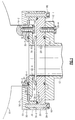
- the numeral 10 generally designates a refrigerant compressor, such as a screw compressor, and the numeral 12 designates a cooler or evaporator of a refrigeration or air conditioning system.
- Compressor 10 has an annular groove 10-1 which receives o-ring 11.
- Diaphragm 30 is secured to compressor 10 by circumferentially spaced bolts 16 which extend through bores 30-7 in diaphragm 30 and are threaded into threaded bores 10-2 in compressor 10.
- Crush washers 18, or the like underlie the heads of bolts 16 to provide a seal.
- an annular groove can be formed in diaphragm 30 in place of annular groove 10-1.
- Flange 12-1 is overlain by annular mounting plate 20 which is illustrated in Figure 3.
- a fluid seal is provided between mounting plate 20 and flange 12-1 by o-ring 21 which is located in an annular groove in either flange 12-1 or plate 20 with groove 20-1 in plate 20 being illustrated.
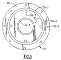
- Diaphragm 30 which is illustrated in Figure 2, overlies plate 20 and peripherally engages, and is supported by, plate 20.
- An o-ring 22 provides a fluid seal between mounting plate 20 and diaphragm 30 and is located in an annular groove in either diaphragm 30 or plate 20 with groove 20-4 in mounting plate 20 being illustrated.
- diaphragm 30 peripherally engages plate 20 and this is due to the fact that the outer portion 30-1 of diaphragm 30 is the portion with the greatest axial thickness. Immediately, radially inward of portion 30-1 is thinnest portion 30-2 which is capable of flexure responsive to compressor induced vibrations, etc.
- portion 30-3 Radially inward of thinnest portion 30-2 is portion 30-3 which is of intermediate thickness such that it is rigid and, in use, supports the weight of compressor 10 but is separated from plate 20.
- Annular extension 30-4 is normally spaced from mounting plate 20 and forms a portion of bore 30-5 which is generally coaxial with bore 20-2 in plate 20 and bore 12-2 in evaporator 12. The engagement of annular extension 30-4 with plate 20 is one extreme position of diaphragm 30.
- Belleville spring or washer 40 surrounds annular extension 30-4 and engages portion 30-3 of diaphragm 30 and plate 20 and tends to keep them separated while supporting the weight of compressor 10.
- Belleville spring 40 is much stiffer than thinnest portion 30-2 and has a spring constant that is on the order of five times higher than that of thinnest portion 30-2.
- Annular restraint 50 is secured to plate 20 and diaphragm 30 by circumferentially spaced bolts 60 which serially extend through bore 20-3 in plate 20, bores 30-6 in diaphragm 30 and are threaded into threaded bores 50-1 in restraint 50.
- Restraint 50 has a radially inwardly extending portion 50-2 which is normally separated from portion 30-2 of diaphragm 30 by a small distance which is on the order of 0.004 inches. Accordingly, the other extreme position of diaphragm 30 is when portion 30-2 engages portion 50-2 of restraint 50.
- Portion 50-2 acts in the manner of a valve stop in that it limits the movement/flexure of diaphragm 30 upon engagement of portion 50-2 by diaphragm 30.
- Mounting plate 20 is secured to the flange 12-1 by bolts 24 which extend through bore 20-4 and are threaded into threaded bore 20-4 of mounting plate 20.
- diaphragm 30 In operation, diaphragm 30 will be separated from portion 50-2 of restraint 50.
- the resilience of diaphragm 30 coupled with the biasing force of Belleville spring 40 normally keeps annular extension 30-4 of diaphragm 30 separated from mounting plate 20. Accordingly, while there is a metal-to-metal contact of the compressor 10 with other members it is through the resilient coupling provided by Belleville spring 40 and thin portion 30-2 of diaphragm 30. Transient movement of diaphragm 30 is limited by portion 50-2 of restraint 50 and by contact between annular extension 30-4 with mounting plate 20. However, such contact is out of the range of movement during normal operation.
Landscapes
- Engineering & Computer Science (AREA)
- General Engineering & Computer Science (AREA)
- Mechanical Engineering (AREA)
- Physics & Mathematics (AREA)
- Acoustics & Sound (AREA)
- Aviation & Aerospace Engineering (AREA)
- Compressor (AREA)
- Diaphragms And Bellows (AREA)
- Coupling Device And Connection With Printed Circuit (AREA)
- Mechanical Coupling Of Light Guides (AREA)
- Connections Arranged To Contact A Plurality Of Conductors (AREA)
- Springs (AREA)
- Cable Accessories (AREA)
Abstract
Description
Claims (4)
- An isolation device and fluid connection for fluidly connecting a first and a second structural member wherein said first structural member is supported by said second structural member and said first and second structural members are in a system requiring fluid communication between said first and second structural members comprising:a first supporting member having an opening therein and a first and second side with said first side adapted to engage said first structural member in a fluid tight relationship;a second supporting member;said first supporting member being of varying axial extent with an outer portion being of greatest axial extent and with an intermediate portion being of least axial extent such that said portion of least axial extent permits flexure, and with an inner portion normally spaced from said second supporting member;said second supporting member having an opening therein and a first and a second side with said first side of said second supporting member adapted to engage said outer portion of said second side of said first supporting member in a fluid tight relationship and second side of said second member adapted to engage said second structural member in a fluid tight relationship;a resilient member located between said first and second supporting members and biasing said inner portion of said first supporting member away from said second supporting member;a restraint axially separated from said intermediate portion of said first supporting member so as to limit movement of said first supporting member in a direction away from said second supporting member.
- The isolation device and fluid connection of claim 1 wherein said resilient member is a Belleville spring.
- The isolation device and fluid connection of claim 2 wherein said Belleville spring has a spring constant much greater than that of said intermediate portion of said first supporting member.
- The isolation device and fluid connection of claim 1 further including means for securing said first and second structural members together with said first and second supporting members therebetween.
Applications Claiming Priority (2)
| Application Number | Priority Date | Filing Date | Title |
|---|---|---|---|
| US09/393,485 US6209927B1 (en) | 1999-09-10 | 1999-09-10 | Isolation device and fluid connection |
| US393485 | 1999-09-10 |
Publications (3)
| Publication Number | Publication Date |
|---|---|
| EP1083363A2 true EP1083363A2 (en) | 2001-03-14 |
| EP1083363A3 EP1083363A3 (en) | 2003-03-26 |
| EP1083363B1 EP1083363B1 (en) | 2005-01-26 |
Family
ID=23554883
Family Applications (1)
| Application Number | Title | Priority Date | Filing Date |
|---|---|---|---|
| EP00307083A Expired - Lifetime EP1083363B1 (en) | 1999-09-10 | 2000-08-18 | Isolation device and fluid connection |
Country Status (5)
| Country | Link |
|---|---|
| US (1) | US6209927B1 (en) |
| EP (1) | EP1083363B1 (en) |
| AT (1) | ATE288040T1 (en) |
| DE (1) | DE60017652T2 (en) |
| DK (1) | DK1083363T3 (en) |
Cited By (1)
| Publication number | Priority date | Publication date | Assignee | Title |
|---|---|---|---|---|
| US4797908A (en) * | 1984-09-14 | 1989-01-10 | Kabushiki Kaisha Toshiba | Voltage-resonance type power supply circuit for X-ray tube |
Families Citing this family (4)
| Publication number | Priority date | Publication date | Assignee | Title |
|---|---|---|---|---|
| US10450823B1 (en) * | 2015-02-09 | 2019-10-22 | Pruitt Tool & Supply Co. | Flange adapter |
| CN107461556B (en) * | 2016-06-03 | 2024-05-03 | 开利公司 | Flange connection assembly, assembling and disassembling method thereof, pipeline connection device and cooler unit |
| US11530601B2 (en) | 2020-07-07 | 2022-12-20 | Safoco, Inc. | Fluid conduit connector system |
| US11519536B2 (en) | 2020-07-07 | 2022-12-06 | Safoco, Inc. | Fluid conduit connector system |
Family Cites Families (14)
| Publication number | Priority date | Publication date | Assignee | Title |
|---|---|---|---|---|
| DE82719C (en) * | ||||
| BE560934A (en) * | ||||
| GB191210199A (en) * | 1912-04-30 | 1913-03-20 | William Downes | An Expansion Joint for Fuel Economisers, Heating Apparatus, or Pipes Carrying Steam, Water or Air. |
| US2038855A (en) * | 1932-05-03 | 1936-04-28 | Rosenblad Curt | Drying cylinder machine |
| US2113047A (en) * | 1936-11-16 | 1938-04-05 | Heil Co | Rotary drier |
| US2632658A (en) * | 1948-12-30 | 1953-03-24 | Traylor Engineering & Mfg Comp | Sealing ring for rotary kilns |
| GB739267A (en) * | 1952-06-10 | 1955-10-26 | Vickers Electrical Co Ltd | Improvements in flexible joints for ducts more particularly for turbines |
| US3249378A (en) * | 1963-12-30 | 1966-05-03 | Gen Electric | Support system |
| CH492158A (en) * | 1968-02-08 | 1970-06-15 | Tech Fortschritt Mbh Ges | Sound-absorbing pipe connector |
| US4182434A (en) * | 1975-03-18 | 1980-01-08 | Erich Munz | Oscillation insulator |
| US4570440A (en) * | 1985-07-02 | 1986-02-18 | Chrysler Corporation | Articulated connector |
| US4718702A (en) * | 1985-11-06 | 1988-01-12 | Northern Research & Engineering Company | Expansible coupling |
| US4804211A (en) * | 1986-09-05 | 1989-02-14 | Dresser-Rand Company | Seal assembly |
| DE4415991A1 (en) * | 1994-05-06 | 1995-11-23 | Witzenmann Metallschlauchfab | Articulated connecting element for pipe parts |
-
1999
- 1999-09-10 US US09/393,485 patent/US6209927B1/en not_active Expired - Fee Related
-
2000
- 2000-08-18 DK DK00307083T patent/DK1083363T3/en active
- 2000-08-18 AT AT00307083T patent/ATE288040T1/en not_active IP Right Cessation
- 2000-08-18 DE DE60017652T patent/DE60017652T2/en not_active Expired - Fee Related
- 2000-08-18 EP EP00307083A patent/EP1083363B1/en not_active Expired - Lifetime
Cited By (1)
| Publication number | Priority date | Publication date | Assignee | Title |
|---|---|---|---|---|
| US4797908A (en) * | 1984-09-14 | 1989-01-10 | Kabushiki Kaisha Toshiba | Voltage-resonance type power supply circuit for X-ray tube |
Also Published As
| Publication number | Publication date |
|---|---|
| EP1083363B1 (en) | 2005-01-26 |
| DK1083363T3 (en) | 2005-06-06 |
| EP1083363A3 (en) | 2003-03-26 |
| US6209927B1 (en) | 2001-04-03 |
| DE60017652D1 (en) | 2005-03-03 |
| DE60017652T2 (en) | 2005-12-22 |
| ATE288040T1 (en) | 2005-02-15 |
Similar Documents
| Publication | Publication Date | Title |
|---|---|---|
| US6394432B1 (en) | Vibration and/or shock absorbing devices and compensator elements utilized therein | |
| US6132183A (en) | Compressor mounting | |
| US4539822A (en) | Vibration isolator for cryopump | |
| CA2147783C (en) | Suction accumulator vibration damper | |
| EP1083363B1 (en) | Isolation device and fluid connection | |
| US5056319A (en) | Refrigerator-operated apparatus | |
| EP3076104A1 (en) | Caulking fixation type power element and expansion valve using the same | |
| CN1991168B (en) | Fixing device and compression equipment with the fixing device | |
| US5732570A (en) | Thermal expansion valve and air conditioning apparatus using the same | |
| EP2947322B1 (en) | Compressor | |
| JP5873991B2 (en) | Compressor fixing structure | |
| US2338953A (en) | Refrigerating apparatus | |
| JPH0381584A (en) | Air-tight compressor provided with elastic inside fitting device | |
| US5114124A (en) | Fluid-filled elastic mount having means for controlling pressure in air chamber in resonance member in pressure-receiving chamber | |
| EP1083377A1 (en) | Vibration isolation device and fluid connection | |
| CN100422666C (en) | Expansion valve | |
| JP7135601B2 (en) | Joint | |
| JPH112439A (en) | Fixed structure of compressor for refrigeration cycle device | |
| EP4481198A1 (en) | Heat pump and method of securing a heat pump for transport | |
| US20100252360A1 (en) | Absorptive muffler suspension | |
| JP6567062B2 (en) | Air conditioner outdoor unit | |
| JP3039299B2 (en) | Outdoor unit of air conditioner | |
| JP2002243312A (en) | Soundproof cover for expansion valve | |
| CN112292544B (en) | Vehicle Assembly - Fixed Structural Assemblies and Modular Systems | |
| KR20040078938A (en) | The forming structure of base plate using air conditioner outdoor unit |
Legal Events
| Date | Code | Title | Description |
|---|---|---|---|
| PUAI | Public reference made under article 153(3) epc to a published international application that has entered the european phase |
Free format text: ORIGINAL CODE: 0009012 |
|
| AK | Designated contracting states |
Kind code of ref document: A2 Designated state(s): AT BE CH CY DE DK ES FI FR GB GR IE IT LI LU MC NL PT SE |
|
| AX | Request for extension of the european patent |
Free format text: AL;LT;LV;MK;RO;SI |
|
| PUAL | Search report despatched |
Free format text: ORIGINAL CODE: 0009013 |
|
| RIC1 | Information provided on ipc code assigned before grant |
Ipc: 7F 16F 15/06 A Ipc: 7F 16L 27/10 B |
|
| AK | Designated contracting states |
Designated state(s): AT BE CH CY DE DK ES FI FR GB GR IE IT LI LU MC NL PT SE Kind code of ref document: A3 Designated state(s): AT BE CH CY DE DK ES FI FR GB GR IE IT LI LU MC NL PT SE |
|
| AX | Request for extension of the european patent |
Extension state: AL LT LV MK RO SI |
|
| 17P | Request for examination filed |
Effective date: 20030227 |
|
| AKX | Designation fees paid |
Designated state(s): AT BE CH CY DE DK ES FI FR GB GR IE IT LI LU MC NL PT SE |
|
| GRAP | Despatch of communication of intention to grant a patent |
Free format text: ORIGINAL CODE: EPIDOSNIGR1 |
|
| GRAS | Grant fee paid |
Free format text: ORIGINAL CODE: EPIDOSNIGR3 |
|
| GRAA | (expected) grant |
Free format text: ORIGINAL CODE: 0009210 |
|
| AK | Designated contracting states |
Kind code of ref document: B1 Designated state(s): AT BE CH CY DE DK ES FI FR GB GR IE IT LI LU MC NL PT SE |
|
| PG25 | Lapsed in a contracting state [announced via postgrant information from national office to epo] |
Ref country code: BE Free format text: LAPSE BECAUSE OF FAILURE TO SUBMIT A TRANSLATION OF THE DESCRIPTION OR TO PAY THE FEE WITHIN THE PRESCRIBED TIME-LIMIT Effective date: 20050126 Ref country code: NL Free format text: LAPSE BECAUSE OF FAILURE TO SUBMIT A TRANSLATION OF THE DESCRIPTION OR TO PAY THE FEE WITHIN THE PRESCRIBED TIME-LIMIT Effective date: 20050126 Ref country code: AT Free format text: LAPSE BECAUSE OF FAILURE TO SUBMIT A TRANSLATION OF THE DESCRIPTION OR TO PAY THE FEE WITHIN THE PRESCRIBED TIME-LIMIT Effective date: 20050126 Ref country code: FI Free format text: LAPSE BECAUSE OF FAILURE TO SUBMIT A TRANSLATION OF THE DESCRIPTION OR TO PAY THE FEE WITHIN THE PRESCRIBED TIME-LIMIT Effective date: 20050126 Ref country code: CH Free format text: LAPSE BECAUSE OF FAILURE TO SUBMIT A TRANSLATION OF THE DESCRIPTION OR TO PAY THE FEE WITHIN THE PRESCRIBED TIME-LIMIT Effective date: 20050126 Ref country code: LI Free format text: LAPSE BECAUSE OF FAILURE TO SUBMIT A TRANSLATION OF THE DESCRIPTION OR TO PAY THE FEE WITHIN THE PRESCRIBED TIME-LIMIT Effective date: 20050126 |
|
| REG | Reference to a national code |
Ref country code: GB Ref legal event code: FG4D |
|
| REG | Reference to a national code |
Ref country code: CH Ref legal event code: EP |
|
| REG | Reference to a national code |
Ref country code: IE Ref legal event code: FG4D |
|
| REF | Corresponds to: |
Ref document number: 60017652 Country of ref document: DE Date of ref document: 20050303 Kind code of ref document: P |
|
| REG | Reference to a national code |
Ref country code: SE Ref legal event code: TRGR |
|
| PG25 | Lapsed in a contracting state [announced via postgrant information from national office to epo] |
Ref country code: GR Free format text: LAPSE BECAUSE OF FAILURE TO SUBMIT A TRANSLATION OF THE DESCRIPTION OR TO PAY THE FEE WITHIN THE PRESCRIBED TIME-LIMIT Effective date: 20050426 |
|
| PG25 | Lapsed in a contracting state [announced via postgrant information from national office to epo] |
Ref country code: ES Free format text: LAPSE BECAUSE OF FAILURE TO SUBMIT A TRANSLATION OF THE DESCRIPTION OR TO PAY THE FEE WITHIN THE PRESCRIBED TIME-LIMIT Effective date: 20050507 |
|
| REG | Reference to a national code |
Ref country code: DK Ref legal event code: T3 |
|
| PGFP | Annual fee paid to national office [announced via postgrant information from national office to epo] |
Ref country code: IE Payment date: 20050630 Year of fee payment: 6 |
|
| NLV1 | Nl: lapsed or annulled due to failure to fulfill the requirements of art. 29p and 29m of the patents act | ||
| PGFP | Annual fee paid to national office [announced via postgrant information from national office to epo] |
Ref country code: LU Payment date: 20050701 Year of fee payment: 6 |
|
| REG | Reference to a national code |
Ref country code: CH Ref legal event code: PL |
|
| PGFP | Annual fee paid to national office [announced via postgrant information from national office to epo] |
Ref country code: MC Payment date: 20050801 Year of fee payment: 6 |
|
| PG25 | Lapsed in a contracting state [announced via postgrant information from national office to epo] |
Ref country code: CY Free format text: LAPSE BECAUSE OF FAILURE TO SUBMIT A TRANSLATION OF THE DESCRIPTION OR TO PAY THE FEE WITHIN THE PRESCRIBED TIME-LIMIT Effective date: 20050818 |
|
| PLBE | No opposition filed within time limit |
Free format text: ORIGINAL CODE: 0009261 |
|
| STAA | Information on the status of an ep patent application or granted ep patent |
Free format text: STATUS: NO OPPOSITION FILED WITHIN TIME LIMIT |
|
| ET | Fr: translation filed | ||
| 26N | No opposition filed |
Effective date: 20051027 |
|
| PG25 | Lapsed in a contracting state [announced via postgrant information from national office to epo] |
Ref country code: IE Free format text: LAPSE BECAUSE OF NON-PAYMENT OF DUE FEES Effective date: 20060818 |
|
| PG25 | Lapsed in a contracting state [announced via postgrant information from national office to epo] |
Ref country code: MC Free format text: LAPSE BECAUSE OF NON-PAYMENT OF DUE FEES Effective date: 20060831 |
|
| REG | Reference to a national code |
Ref country code: IE Ref legal event code: MM4A |
|
| PGFP | Annual fee paid to national office [announced via postgrant information from national office to epo] |
Ref country code: DK Payment date: 20070710 Year of fee payment: 8 |
|
| PG25 | Lapsed in a contracting state [announced via postgrant information from national office to epo] |
Ref country code: PT Free format text: LAPSE BECAUSE OF NON-PAYMENT OF DUE FEES Effective date: 20050626 |
|
| PGFP | Annual fee paid to national office [announced via postgrant information from national office to epo] |
Ref country code: SE Payment date: 20070802 Year of fee payment: 8 |
|
| PG25 | Lapsed in a contracting state [announced via postgrant information from national office to epo] |
Ref country code: LU Free format text: LAPSE BECAUSE OF NON-PAYMENT OF DUE FEES Effective date: 20060818 |
|
| PGFP | Annual fee paid to national office [announced via postgrant information from national office to epo] |
Ref country code: DE Payment date: 20080829 Year of fee payment: 9 |
|
| PGFP | Annual fee paid to national office [announced via postgrant information from national office to epo] |
Ref country code: FR Payment date: 20080807 Year of fee payment: 9 Ref country code: IT Payment date: 20080816 Year of fee payment: 9 |
|
| PGFP | Annual fee paid to national office [announced via postgrant information from national office to epo] |
Ref country code: GB Payment date: 20080708 Year of fee payment: 9 |
|
| REG | Reference to a national code |
Ref country code: DK Ref legal event code: EBP |
|
| EUG | Se: european patent has lapsed | ||
| PG25 | Lapsed in a contracting state [announced via postgrant information from national office to epo] |
Ref country code: DK Free format text: LAPSE BECAUSE OF NON-PAYMENT OF DUE FEES Effective date: 20080831 |
|
| GBPC | Gb: european patent ceased through non-payment of renewal fee |
Effective date: 20090818 |
|
| REG | Reference to a national code |
Ref country code: FR Ref legal event code: ST Effective date: 20100430 |
|
| PG25 | Lapsed in a contracting state [announced via postgrant information from national office to epo] |
Ref country code: SE Free format text: LAPSE BECAUSE OF NON-PAYMENT OF DUE FEES Effective date: 20080819 Ref country code: DE Free format text: LAPSE BECAUSE OF NON-PAYMENT OF DUE FEES Effective date: 20100302 Ref country code: FR Free format text: LAPSE BECAUSE OF NON-PAYMENT OF DUE FEES Effective date: 20090831 |
|
| PG25 | Lapsed in a contracting state [announced via postgrant information from national office to epo] |
Ref country code: GB Free format text: LAPSE BECAUSE OF NON-PAYMENT OF DUE FEES Effective date: 20090818 |
|
| PG25 | Lapsed in a contracting state [announced via postgrant information from national office to epo] |
Ref country code: IT Free format text: LAPSE BECAUSE OF NON-PAYMENT OF DUE FEES Effective date: 20090818 |