EP1083071A2 - Verdeckelement eines Cabrioverdecks und Cabrioverdeck - Google Patents
Verdeckelement eines Cabrioverdecks und Cabrioverdeck Download PDFInfo
- Publication number
- EP1083071A2 EP1083071A2 EP00118356A EP00118356A EP1083071A2 EP 1083071 A2 EP1083071 A2 EP 1083071A2 EP 00118356 A EP00118356 A EP 00118356A EP 00118356 A EP00118356 A EP 00118356A EP 1083071 A2 EP1083071 A2 EP 1083071A2
- Authority
- EP
- European Patent Office
- Prior art keywords
- convertible top
- plastic component
- top element
- element according
- sheet metal
- Prior art date
- Legal status (The legal status is an assumption and is not a legal conclusion. Google has not performed a legal analysis and makes no representation as to the accuracy of the status listed.)
- Granted
Links
- 239000004033 plastic Substances 0.000 claims abstract description 62
- 229920003023 plastic Polymers 0.000 claims abstract description 62
- 229910052751 metal Inorganic materials 0.000 claims abstract description 42
- 239000002184 metal Substances 0.000 claims abstract description 42
- 239000002131 composite material Substances 0.000 claims abstract description 24
- 206010041662 Splinter Diseases 0.000 claims description 5
- 238000002347 injection Methods 0.000 claims description 2
- 239000007924 injection Substances 0.000 claims description 2
- 238000004382 potting Methods 0.000 claims description 2
- 230000002787 reinforcement Effects 0.000 claims description 2
- 238000004026 adhesive bonding Methods 0.000 claims 1
- 238000005452 bending Methods 0.000 description 6
- 238000010276 construction Methods 0.000 description 3
- 238000005304 joining Methods 0.000 description 3
- 238000004519 manufacturing process Methods 0.000 description 3
- 229910052782 aluminium Inorganic materials 0.000 description 2
- XAGFODPZIPBFFR-UHFFFAOYSA-N aluminium Chemical compound [Al] XAGFODPZIPBFFR-UHFFFAOYSA-N 0.000 description 2
- 238000005260 corrosion Methods 0.000 description 2
- 230000007797 corrosion Effects 0.000 description 2
- 238000000034 method Methods 0.000 description 2
- FYYHWMGAXLPEAU-UHFFFAOYSA-N Magnesium Chemical compound [Mg] FYYHWMGAXLPEAU-UHFFFAOYSA-N 0.000 description 1
- 239000004952 Polyamide Substances 0.000 description 1
- 229910000831 Steel Inorganic materials 0.000 description 1
- 208000027418 Wounds and injury Diseases 0.000 description 1
- 230000015572 biosynthetic process Effects 0.000 description 1
- 238000005266 casting Methods 0.000 description 1
- 230000006378 damage Effects 0.000 description 1
- 238000004512 die casting Methods 0.000 description 1
- 238000005242 forging Methods 0.000 description 1
- 238000005755 formation reaction Methods 0.000 description 1
- 239000012634 fragment Substances 0.000 description 1
- 238000007373 indentation Methods 0.000 description 1
- 208000014674 injury Diseases 0.000 description 1
- 238000003754 machining Methods 0.000 description 1
- 229910052749 magnesium Inorganic materials 0.000 description 1
- 239000011777 magnesium Substances 0.000 description 1
- 239000000463 material Substances 0.000 description 1
- 230000003287 optical effect Effects 0.000 description 1
- 229920002647 polyamide Polymers 0.000 description 1
- 239000010959 steel Substances 0.000 description 1
Images


Classifications
-
- B—PERFORMING OPERATIONS; TRANSPORTING
- B60—VEHICLES IN GENERAL
- B60J—WINDOWS, WINDSCREENS, NON-FIXED ROOFS, DOORS, OR SIMILAR DEVICES FOR VEHICLES; REMOVABLE EXTERNAL PROTECTIVE COVERINGS SPECIALLY ADAPTED FOR VEHICLES
- B60J7/00—Non-fixed roofs; Roofs with movable panels, e.g. rotary sunroofs
- B60J7/08—Non-fixed roofs; Roofs with movable panels, e.g. rotary sunroofs of non-sliding type, i.e. movable or removable roofs or panels, e.g. let-down tops or roofs capable of being easily detached or of assuming a collapsed or inoperative position
- B60J7/12—Non-fixed roofs; Roofs with movable panels, e.g. rotary sunroofs of non-sliding type, i.e. movable or removable roofs or panels, e.g. let-down tops or roofs capable of being easily detached or of assuming a collapsed or inoperative position foldable; Tensioning mechanisms therefor, e.g. struts
- B60J7/1226—Soft tops for convertible vehicles
- B60J7/1234—Soft tops for convertible vehicles characterised by arches, e.g. shape or material
- B60J7/1239—Front bow
Definitions
- the invention relates to a top element of a convertible top and a convertible top.
- the first-mentioned object is achieved in that the convertible top element from a plastic component and from a sheet metal part as a composite component is formed.
- a composite construction offers the possibility of Combining the advantages of sheet metal with those of plastic and leads in the Roof parts proposed according to the invention to save weight with at least constant or even increased bending and torsional rigidity.
- Plastic also has the advantage that corrosion protection is not required is and that desired colorations and surface structures are immediate can be taken into account during production.
- the essential Areas are considered depending on the component shape of the strength requirements and can, depending on the type of Convertible top element at different locations on the convertible top element. Preferably these major, spaced areas form the predominant Size share of the plastic component or the entire convertible top element.
- plastic component and the sheet metal part with a thin-walled composite part form at least one large-volume cavity, so a particularly light Composite component are formed, which still has high strength requirements Fulfills.
- the size of the entire component and in particular its extent at the largest cross section of the cavity only from that available Limited space for the closed and open convertible top.
- the sheet metal part is expediently glued to the plastic component, Joining or potting, but any other joining and joining techniques can be used.
- the sheet metal part can, for. B. has been brought into the required shape by deep drawing his.
- the sheet can be particularly thin and therefore also light, since it is his Support function only in arrangement on the composite part.
- the plastic component can be produced as an injection molded part, deep-drawn part or laminate part, whereby great freedom of design is guaranteed and also for the attachment of the sheet required contact surfaces are optimally shaped can.
- the Sheet metal part and the plastic component can be selected for the construction of the composite part. So the sheet metal part Bottom or inside and the plastic component the top or outside of the Composite part of the convertible top, especially in its arrangement when closed Convertible top, form. On the other hand, the plastic component the bottom or inside and the sheet metal part the top or outside of the composite part form.
- the arrangement is essentially taking into account the Applying a decor and the breaking behavior of the used one Materials such as in particular the plastic selected.
- a high strength, however splinter-breaking plastic is placed on the outside of the convertible top and is covered inside by a sheet metal towards the passengers.
- the convertible top element is preferably a front bow of the convertible top, wherein the plastic component is a front bow lower part and the sheet metal part is a front bow upper part is.
- the plastic component of the Front bow has an essentially U-shaped transverse channel.
- these Cross channel can be additional components such as locking devices or drives be included and integrated.
- the plastic component reinforcements and in particular has stiffening ribs. If the stiffening ribs up to enough roof contour, they can serve as a support and support for the sheet metal part.
- Additional sheet metal parts can also be inserted or integrated into the plastic component be that can be connected directly to the sheet metal part.
- plastic component different plastics such. B. polyamide (PA6.6) are used, the plastic component being made in particular from a Plastic is formed with an essentially splinter-free breaking behavior, when it faces the vehicle interior.
- PA6.6 polyamide
- a convertible top linkage part also expediently comes as a convertible top element, such as in particular a roof link, a control link, a main pillar, a crossbar, a front bow or a rooftop or one of at least two of these Rod parts combined part into consideration, whereby here the advantages of Composite construction with a plastic component due to the freedom of design have a particularly positive impact.
- the convertible top has at least one top element, which is formed as a composite part which is a combination of a sheet metal part with a plastic component is made.
- the top element is expedient according to the above Designs designed and is in particular a roof link, a control link, a main pillar, a cross bow, a front bow or a roof top.
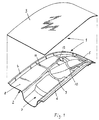
- a front bow 1 of a convertible top contains a plastic component 2 as the lower part and an attached shell-like sheet metal part 3 made of steel or Aluminum sheet as the upper part (see Fig. 1 and 2).
- the plastic component 2 has a front edge surface 4, a side edge surface 5 and a rear edge surface 6 on which determine the shape of the roof contour and on which this corresponds to the Roof contour in arched or convex shape brought sheet metal part 3 and attached, in particular glued.
- the front bow 1 is thus a composite part formed from the plastic part 2 and the sheet metal part 3.
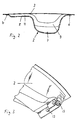
- the plastic component 2 contains an approximately U-shaped recess in the longitudinal cross section Cross member section 7, which extends substantially over the entire width of the front bow 1 extends and the composite part due to the voluminous Box hollow profile gives a high bending and torsional rigidity. It can in Middle region of the front bow 1 of the cross member section 7 a more trained Have indentation in this area of high stress to provide sufficient rigidity.
- a front section of the plastic component 2 is from the front edge surface 4 stepped shallow depression 8 formed due to their distance to Sheet metal part 3 also contributes to component strength.
- One or more longitudinal webs 9 and 10 are formed on the inside 11 of the plastic component 2 and extend from the front edge surface 4 to the rear edge surface 6. They stiffen the Plastic component 2 and additionally offer in a front section 11 or 12 a support and support for the sheet metal part 3, which either only rests on it or is also glued. Additional stiffening ribs can be used in highly stressed Component areas may be provided.
- articulation points 13 (see Fig. 3) or handlebar bearings for Auxiliary links on the two opposite sides of the front bow 1 are incorporated as metal or sheet metal parts in the manufacture of the plastic component 2 and integrated as inserts or subsequently in corresponding recesses used, which are molded into the plastic component 2 or by subsequent Machining are made in this.
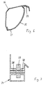
- a main pillar 14 (see FIG. 4) of the convertible top is another top element a plastic part 15 and a sheet metal part 16 glued to it manufactured as a composite part.
- the connection of the plastic part 15 to the sheet metal part 16 takes place on edge sections 21 and 22 of the plastic part 15 (see FIG. 6).
- By the voluminous cavity cross section of the main column 14 is also in this Composite part achieves high bending and torsional rigidity.
- FIG. 5 Another example of a convertible top element formed as a composite part is shown in FIG. 5 is shown in a half view and shows a roof assembly 23, each a lateral roof link 24 and a bow connecting the roof link 24 25, e.g. B. contains a central or main bow of the convertible top, the from a plastic part formed in one piece with the lateral roof links 24 26 and a sheet metal part 27, which is glued to the plastic part 26 from below is.
- the plastic part 26 is made of a high-strength plastic.
- the roof handlebar 24 In the roof handlebar 24 are bearings 28 for articulated connections with handlebars 29 (see also Fig. 7) formed.
- the box-shaped profile of the roof link 24 offers the necessary Bending and torsional stiffness.
Landscapes
- Engineering & Computer Science (AREA)
- Mechanical Engineering (AREA)
- Body Structure For Vehicles (AREA)
Abstract
Description
- Fig. 1
- in einer perspektivischen Oberansicht in Explosionsdarstellung die rechte Hälfte eines Frontspriegels eines Cabrioverdecks mit einem unteren Kunststoffbauteil und einem oberen Deckblech;
- Fig. 2
- einen Längsquerschnitt des Frontspriegels in schematischer Darstellung;
- Fig. 3
- in einer perspektivischen Unteransicht den rechten Randbereich des Frontspriegels;
- Fig. 4
- in einer perspektivischen Draufsicht eine Hauptsäule eines Cabrioverdecks;
- Fig. 5
- in einer perspektivischen Oberansicht einen Mittelspriegel mit einem daran angeformten seitlichen Dachlenker des Cabrioverdecks;
- Fig. 6
- eine Querschnittsansicht der in Fig. 4 dargestellten Hauptsäule; und
- Fig. 7
- eine Querschnittsansicht des dargestellten Dachlenkers entlang der
Schnittfläche
A ― A in Fig. 5.
Claims (19)
- Verdeckelement für ein Cabrioverdeck,
dadurch gekennzeichnet,
daß es aus einem Kunststoffbauteil (2; 15; 26) und aus einem Blechteil (3; 16; 27) als Verbundbauteil gebildet ist. - Verdeckelement nach Anspruch 1,
dadurch gekennzeichnet, daß wesentliche Bereiche des Kunststoffbauteils (2; 15; 26) und des Blechteils (3; 16; 27) voneinander beabstandet sind und eine steife Hohlraumstruktur bilden. - Verdeckelement nach Anspruch 2,
dadurch gekennzeichnet, daß die wesentlichen, beabstandeten Bereiche den überwiegenden Größenanteil des Kunststoffbauteils (2; 15; 26) bzw. des Verdeckelements bilden. - Verdeckelement nach einem der Ansprüche 1 bis 3,
dadurch gekennzeichnet, daß das Kunststoffbauteil (2; 15; 26) und das Blechteil (3; 16; 27) ein dünnwandiges Verbundteil mit zumindest einem großvolumigen Hohlraum bilden. - Verdeckelement nach einem der Ansprüche 1 bis 4,
dadurch gekennzeichnet, daß das Blechteil (3; 16; 27) mit dem Kunststoffbauteil (2; 15; 26) durch Kleben, Clinchen oder Vergießen verbunden ist. - Verdeckelement nach einem der Ansprüche 1 bis 5,
dadurch gekennzeichnet, daß das Blechteil (3; 16; 27) als Tiefziehteil hergestellt ist. - Verdeckelement nach einem der Ansprüche 1 bis 6,
dadurch gekennzeichnet, daß das Kunststoffbauteil (2; 15; 26) als Spritzgußteil, Tiefziehteil oder Laminatteil hergestellt ist. - Verdeckelement nach einem der Ansprüche 1 bis 7,
dadurch gekennzeichnet, daß das Blechteil (3; 16; 27) die Unter- oder Innenseite und das Kunststoffbauteil (2; 15; 26) die Ober- oder Außenseite des Verbundteils des Cabrioverdecks, insbesondere in seiner Anordnung bei geschlossenem Cabrioverdeck, bildet. - Verdeckelement nach einem der Ansprüche 1 bis 7,
dadurch gekennzeichnet, daß das Kunststoffbauteil (2; 15; 26) die Unter- oder Innenseite und das Blechteil (3; 16; 27) die Ober- oder Außenseite des Verbundteils des Cabrioverdecks, insbesondere in seiner Anordnung bei geschlossenem Cabrioverdeck, bildet. - Verdeckelement nach einem der Ansprüche 1 bis 9,
dadurch gekennzeichnet, daß es ein Frontspriegel (1) des Cabrioverdecks ist und daß das Kunststoffbauteil (2) ein Frontspriegelunterteil und das Blechteil (3) ein Frontspriegeloberteil ist. - Verdeckelement nach Anspruch 10,
dadurch gekennzeichnet, daß das Kunststoffbauteil (2) des Frontspriegels (1) einen im wesentlichen U-förmigen Querkanal (7) aufweist. - Verdeckelement nach einem der Ansprüche 1 bis 11,
dadurch gekennzeichnet, daß das Kunststoffbauteil (2) Verstärkungen und insbesondere Versteifungsrippen (11, 12) aufweist. - Verdeckelement nach einem der Ansprüche 1 bis 12,
dadurch gekennzeichnet, daß in das Verbundteil weitere Bauteile integriert sind. - Verdeckelement nach einem der Ansprüche 1 bis 13,
dadurch gekennzeichnet, daß in dem Kunststoffbauteil (2; 15; 26) Aufnahmen für Gelenklager von Lenkern oder Führungen ausgebildet sind. - Verdeckelement nach einem der Ansprüche 1 bis 14,
dadurch gekennzeichnet, daß ein Zusatzblechteil in das Kunststoffbauteil (2; 15; 26) eingelegt oder integriert ist. - Verdeckelement nach einem der Ansprüche 1 bis 15,
dadurch gekennzeichnet, daß das Kunststoffbauteil (2; 15; 26) aus einem Kunststoff mit einem im wesentlichen splitterfreien Bruchverhalten gebildet ist. - Verdeckelement nach einem der Ansprüche 1 bis 16,
dadurch gekennzeichnet, daß es ein Verdeckgestängeteil wie insbesondere ein Dachlenker, ein Steuerlenker, eine Hauptsäule, ein Querspriegel, ein Frontspriegel oder eine Dachspitze oder ein aus zumindest zwei dieser Gestängeteile kombiniertes Teil ist. - Cabrioverdeck,
dadurch gekennzeichnet, daß es zumindest ein Verdeckelement aufweist, das als Verbundteil gebildet ist, welches aus einer Kombination eines Blechteils mit einem Kunststoffbauteil hergestellt ist. - Cabrioverdeck nach Anspruch 18,
dadurch gekennzeichnet, daß das Verdeckelement nach einem der Ansprüche 1 bis 17 gebildet ist und insbesondere ein Dachlenker, ein Steuerlenker, eine Hauptsäule, ein Querspriegel, ein Frontspriegel oder eine Dachspitze ist.
Applications Claiming Priority (2)
| Application Number | Priority Date | Filing Date | Title |
|---|---|---|---|
| DE19940935A DE19940935A1 (de) | 1999-08-27 | 1999-08-27 | Verdeckelement eines Cabrioverdecks und Cabrioverdeck |
| DE19940935 | 1999-08-27 |
Publications (3)
| Publication Number | Publication Date |
|---|---|
| EP1083071A2 true EP1083071A2 (de) | 2001-03-14 |
| EP1083071A3 EP1083071A3 (de) | 2002-06-19 |
| EP1083071B1 EP1083071B1 (de) | 2007-10-24 |
Family
ID=7919958
Family Applications (1)
| Application Number | Title | Priority Date | Filing Date |
|---|---|---|---|
| EP00118356A Expired - Lifetime EP1083071B1 (de) | 1999-08-27 | 2000-08-24 | Verdeckelement eines Cabrioverdecks und Cabrioverdeck |
Country Status (4)
| Country | Link |
|---|---|
| US (1) | US6447046B1 (de) |
| EP (1) | EP1083071B1 (de) |
| JP (1) | JP5044068B2 (de) |
| DE (2) | DE19940935A1 (de) |
Families Citing this family (7)
| Publication number | Priority date | Publication date | Assignee | Title |
|---|---|---|---|---|
| DE20306583U1 (de) | 2003-04-29 | 2003-08-07 | Wilhelm Karmann GmbH, 49084 Osnabrück | Cabriolet-Fahrzeug |
| US7111892B2 (en) * | 2004-05-03 | 2006-09-26 | Asc Incorporated | Polymeric roof rail |
| US20060038320A1 (en) * | 2004-08-17 | 2006-02-23 | Straub Martin L | Convertible boot system and method of making same |
| DE102007059077A1 (de) * | 2007-12-07 | 2009-06-10 | Wilhelm Karmann Gmbh | Verdeck eines Cabriolet-Fahrzeugs |
| DE102009020941A1 (de) | 2009-05-12 | 2010-11-25 | Magna Car Top Systems Gmbh | Dachkappe eines Faltverdecks für einen Personenkraftwagen |
| DE102009057631B4 (de) * | 2009-12-06 | 2022-06-02 | Audi Ag | Finnen für ein Faltverdeck |
| DE102015206071B4 (de) | 2015-04-02 | 2022-04-14 | Magna Car Top Systems Gmbh | Verstellbares Faltverdeck eines Cabriolet-Fahrzeugs, sowie Verfahren zur Herstellung einer Dachkappe für ein verstellbares Faltverdeck |
Family Cites Families (19)
| Publication number | Priority date | Publication date | Assignee | Title |
|---|---|---|---|---|
| US261287A (en) * | 1882-07-18 | Carriage-bow | ||
| US2577671A (en) * | 1947-12-05 | 1951-12-04 | Detroit Gasket & Mfg Company | Linear structural member |
| JPS56158318U (de) * | 1980-04-28 | 1981-11-26 | ||
| DE3147214A1 (de) * | 1981-11-28 | 1983-06-09 | Dr.Ing.H.C. F. Porsche Ag, 7000 Stuttgart | "faltverdeck fuer fahrzeuge, insbesondere personenkraftwagen" |
| US4529243A (en) * | 1983-04-29 | 1985-07-16 | Asc Incorporated | Vehicle with a convertible top |
| JPS61132165U (de) * | 1985-02-07 | 1986-08-18 | ||
| JPS61145076U (de) * | 1985-03-01 | 1986-09-06 | ||
| JPS61271174A (ja) * | 1985-05-24 | 1986-12-01 | Daihatsu Motor Co Ltd | 自動車のパネル |
| FR2601906B1 (fr) * | 1986-07-24 | 1989-07-21 | Heuliez Henri France Design | Capote escamotable a arceaux de securite, pour cabriolets automobiles. |
| JPS6444215U (de) * | 1987-09-11 | 1989-03-16 | ||
| US4840420A (en) * | 1987-11-06 | 1989-06-20 | Weber Darrell A | Convertible top |
| DE4001136A1 (de) * | 1990-01-17 | 1991-07-18 | Karmann Gmbh W | Verdeck fuer kabrio-fahrzeuge |
| US5154462A (en) * | 1991-12-23 | 1992-10-13 | Ford Motor Company | Method for making a bonded vehicular cross member bumper beam from two materials |
| US5511844A (en) * | 1993-10-22 | 1996-04-30 | Dura Convertible Systems, Inc. | Convertible top having slidably replaceable bow |
| DE69424667T2 (de) * | 1994-08-28 | 2001-02-08 | Jeroen Van Bon | Faltverdeck für Kraftfahrzeug |
| US5673959B1 (en) * | 1994-11-28 | 2000-05-02 | Craig W Padlo | Foldable convertible flexible-roof support |
| DE19707019B4 (de) * | 1996-02-26 | 2006-08-10 | Dura Convertible Systems, Inc., Adrian | Hybridkopfstück für ein Kabrioverdeck |
| US5904114A (en) * | 1997-12-23 | 1999-05-18 | Wright; Robert L. | Personal watercraft canopy |
| US6135535A (en) * | 1999-12-21 | 2000-10-24 | Larry J. Winget | Removable hard top for an automotive vehicle and method of making a composite removable hard top |
-
1999
- 1999-08-27 DE DE19940935A patent/DE19940935A1/de not_active Withdrawn
-
2000
- 2000-08-24 DE DE50014726T patent/DE50014726D1/de not_active Expired - Lifetime
- 2000-08-24 EP EP00118356A patent/EP1083071B1/de not_active Expired - Lifetime
- 2000-08-25 JP JP2000255495A patent/JP5044068B2/ja not_active Expired - Lifetime
- 2000-08-28 US US09/649,809 patent/US6447046B1/en not_active Expired - Lifetime
Also Published As
| Publication number | Publication date |
|---|---|
| DE19940935A1 (de) | 2001-03-22 |
| DE50014726D1 (de) | 2007-12-06 |
| JP5044068B2 (ja) | 2012-10-10 |
| JP2001105884A (ja) | 2001-04-17 |
| US6447046B1 (en) | 2002-09-10 |
| EP1083071B1 (de) | 2007-10-24 |
| EP1083071A3 (de) | 2002-06-19 |
Similar Documents
| Publication | Publication Date | Title |
|---|---|---|
| EP1532039B1 (de) | Karosserie für einen kraftwagen | |
| DE102007006722C5 (de) | Träger für eine Karosserie eines Kraftwagens | |
| DE10239990B4 (de) | Kraftwagen-Karosserie mit einer Tragstruktur aus großformatigen Teilmodulen | |
| EP0648630B1 (de) | Cabriolet-Verdeck | |
| EP1955931B1 (de) | Vordewagenstruktur eines Kraftfahrzeuges | |
| DE102012204314B4 (de) | Fahrzeugtüranordnung | |
| EP0493774B1 (de) | Kabinentür für eine Fahrzeugkabine | |
| EP1914097A2 (de) | Rahmen für ein Kraftfahrzeugdach | |
| DE10063417A1 (de) | Leichtbautür für Kraftfahrzeuge | |
| DE102008006006A1 (de) | Hilfsrahmen | |
| EP3221168B1 (de) | Rahmen eines fahrzeugdachs und dessen herstellung | |
| EP1340655A1 (de) | Schutzvorrichtung eines PKW-Cabriolets | |
| DE102016123879A1 (de) | Fahrzeug mit schiebedach und panoramaglas | |
| EP1288109A2 (de) | Kraftfahrzeug mit einem in einem Fahrzeugendbereich angeordneten Aufnahmeraum | |
| DE10133421B4 (de) | Kraftfahrzeugtür | |
| DE19728546A1 (de) | Deckelkörper für ein Fahrzeug sowie darin verbaubarer Rahmenkörper | |
| WO1997039937B1 (de) | Bodengruppe eines fahrzeuges mit mitteln zur erhöhung des insassenschutzes | |
| EP1083071B1 (de) | Verdeckelement eines Cabrioverdecks und Cabrioverdeck | |
| DE10252475A1 (de) | Kraftfahrzeugkarosserie in zweischaliger Bauweise | |
| DE60123731T2 (de) | Karosserieseitenteil für ein Kraftfahrzeug | |
| DE19829832B4 (de) | Karosseriestruktur für ein Kraftfahrzeug | |
| EP1203678A2 (de) | Gussteil als Krafteinleitungsstelle zur Befestigung einer tragenden Struktur für Karosseriebauteile | |
| EP1488986A1 (de) | Kraftfahrzeug mit einer Verbindungsanordnung im Dachbereich | |
| EP2018311B1 (de) | Fahrzeugbauteil mit einer versteifung | |
| EP1424235B1 (de) | Abnehmbares Dach für ein Kraftfahrzeug |
Legal Events
| Date | Code | Title | Description |
|---|---|---|---|
| PUAI | Public reference made under article 153(3) epc to a published international application that has entered the european phase |
Free format text: ORIGINAL CODE: 0009012 |
|
| AK | Designated contracting states |
Kind code of ref document: A2 Designated state(s): AT BE CH CY DE DK ES FI FR GB GR IE IT LI LU MC NL PT SE |
|
| AX | Request for extension of the european patent |
Free format text: AL;LT;LV;MK;RO;SI |
|
| PUAL | Search report despatched |
Free format text: ORIGINAL CODE: 0009013 |
|
| AK | Designated contracting states |
Kind code of ref document: A3 Designated state(s): AT BE CH CY DE DK ES FI FR GB GR IE IT LI LU MC NL PT SE |
|
| AX | Request for extension of the european patent |
Free format text: AL;LT;LV;MK;RO;SI |
|
| 17P | Request for examination filed |
Effective date: 20021130 |
|
| AKX | Designation fees paid |
Designated state(s): DE FR GB IT |
|
| GRAP | Despatch of communication of intention to grant a patent |
Free format text: ORIGINAL CODE: EPIDOSNIGR1 |
|
| RAP1 | Party data changed (applicant data changed or rights of an application transferred) |
Owner name: WEBASTO AG |
|
| GRAS | Grant fee paid |
Free format text: ORIGINAL CODE: EPIDOSNIGR3 |
|
| GRAA | (expected) grant |
Free format text: ORIGINAL CODE: 0009210 |
|
| AK | Designated contracting states |
Kind code of ref document: B1 Designated state(s): DE FR GB IT |
|
| REG | Reference to a national code |
Ref country code: GB Ref legal event code: FG4D Free format text: NOT ENGLISH |
|
| GBT | Gb: translation of ep patent filed (gb section 77(6)(a)/1977) |
Effective date: 20071107 |
|
| REF | Corresponds to: |
Ref document number: 50014726 Country of ref document: DE Date of ref document: 20071206 Kind code of ref document: P |
|
| ET | Fr: translation filed | ||
| PLBE | No opposition filed within time limit |
Free format text: ORIGINAL CODE: 0009261 |
|
| STAA | Information on the status of an ep patent application or granted ep patent |
Free format text: STATUS: NO OPPOSITION FILED WITHIN TIME LIMIT |
|
| 26N | No opposition filed |
Effective date: 20080725 |
|
| PG25 | Lapsed in a contracting state [announced via postgrant information from national office to epo] |
Ref country code: IT Free format text: LAPSE BECAUSE OF NON-PAYMENT OF DUE FEES Effective date: 20080831 |
|
| REG | Reference to a national code |
Ref country code: FR Ref legal event code: PLFP Year of fee payment: 16 |
|
| PGFP | Annual fee paid to national office [announced via postgrant information from national office to epo] |
Ref country code: GB Payment date: 20150824 Year of fee payment: 16 |
|
| PGFP | Annual fee paid to national office [announced via postgrant information from national office to epo] |
Ref country code: FR Payment date: 20150824 Year of fee payment: 16 |
|
| GBPC | Gb: european patent ceased through non-payment of renewal fee |
Effective date: 20160824 |
|
| REG | Reference to a national code |
Ref country code: FR Ref legal event code: ST Effective date: 20170428 |
|
| PG25 | Lapsed in a contracting state [announced via postgrant information from national office to epo] |
Ref country code: GB Free format text: LAPSE BECAUSE OF NON-PAYMENT OF DUE FEES Effective date: 20160824 Ref country code: FR Free format text: LAPSE BECAUSE OF NON-PAYMENT OF DUE FEES Effective date: 20160831 |
|
| PGFP | Annual fee paid to national office [announced via postgrant information from national office to epo] |
Ref country code: DE Payment date: 20190822 Year of fee payment: 20 |
|
| REG | Reference to a national code |
Ref country code: DE Ref legal event code: R071 Ref document number: 50014726 Country of ref document: DE |