EP1083066A2 - Annular safety support for vehicle tyre, and wheel containing the same - Google Patents
Annular safety support for vehicle tyre, and wheel containing the same Download PDFInfo
- Publication number
- EP1083066A2 EP1083066A2 EP00119215A EP00119215A EP1083066A2 EP 1083066 A2 EP1083066 A2 EP 1083066A2 EP 00119215 A EP00119215 A EP 00119215A EP 00119215 A EP00119215 A EP 00119215A EP 1083066 A2 EP1083066 A2 EP 1083066A2
- Authority
- EP
- European Patent Office
- Prior art keywords
- profile
- rim
- support body
- features
- bead
- Prior art date
- Legal status (The legal status is an assumption and is not a legal conclusion. Google has not performed a legal analysis and makes no representation as to the accuracy of the status listed.)
- Granted
Links
Images


Classifications
-
- B—PERFORMING OPERATIONS; TRANSPORTING
- B60—VEHICLES IN GENERAL
- B60C—VEHICLE TYRES; TYRE INFLATION; TYRE CHANGING; CONNECTING VALVES TO INFLATABLE ELASTIC BODIES IN GENERAL; DEVICES OR ARRANGEMENTS RELATED TO TYRES
- B60C15/00—Tyre beads, e.g. ply turn-up or overlap
- B60C15/02—Seating or securing beads on rims
- B60C15/0203—Seating or securing beads on rims using axially extending bead seating, i.e. the bead and the lower sidewall portion extend in the axial direction
-
- B—PERFORMING OPERATIONS; TRANSPORTING
- B60—VEHICLES IN GENERAL
- B60C—VEHICLE TYRES; TYRE INFLATION; TYRE CHANGING; CONNECTING VALVES TO INFLATABLE ELASTIC BODIES IN GENERAL; DEVICES OR ARRANGEMENTS RELATED TO TYRES
- B60C15/00—Tyre beads, e.g. ply turn-up or overlap
- B60C15/02—Seating or securing beads on rims
- B60C15/0206—Seating or securing beads on rims using inside rim bead seating, i.e. the bead being seated at a radially inner side of the rim
-
- B—PERFORMING OPERATIONS; TRANSPORTING
- B60—VEHICLES IN GENERAL
- B60C—VEHICLE TYRES; TYRE INFLATION; TYRE CHANGING; CONNECTING VALVES TO INFLATABLE ELASTIC BODIES IN GENERAL; DEVICES OR ARRANGEMENTS RELATED TO TYRES
- B60C15/00—Tyre beads, e.g. ply turn-up or overlap
- B60C15/02—Seating or securing beads on rims
- B60C15/0209—Supplementary means for securing the bead
- B60C15/0213—Supplementary means for securing the bead the bead being clamped by rings, cables, rim flanges or other parts of the rim
-
- B—PERFORMING OPERATIONS; TRANSPORTING
- B60—VEHICLES IN GENERAL
- B60C—VEHICLE TYRES; TYRE INFLATION; TYRE CHANGING; CONNECTING VALVES TO INFLATABLE ELASTIC BODIES IN GENERAL; DEVICES OR ARRANGEMENTS RELATED TO TYRES
- B60C17/00—Tyres characterised by means enabling restricted operation in damaged or deflated condition; Accessories therefor
- B60C17/04—Tyres characterised by means enabling restricted operation in damaged or deflated condition; Accessories therefor utilising additional non-inflatable supports which become load-supporting in emergency
- B60C17/047—Tyres characterised by means enabling restricted operation in damaged or deflated condition; Accessories therefor utilising additional non-inflatable supports which become load-supporting in emergency comprising circumferential ribs
-
- B—PERFORMING OPERATIONS; TRANSPORTING
- B60—VEHICLES IN GENERAL
- B60C—VEHICLE TYRES; TYRE INFLATION; TYRE CHANGING; CONNECTING VALVES TO INFLATABLE ELASTIC BODIES IN GENERAL; DEVICES OR ARRANGEMENTS RELATED TO TYRES
- B60C17/00—Tyres characterised by means enabling restricted operation in damaged or deflated condition; Accessories therefor
- B60C17/04—Tyres characterised by means enabling restricted operation in damaged or deflated condition; Accessories therefor utilising additional non-inflatable supports which become load-supporting in emergency
- B60C17/06—Tyres characterised by means enabling restricted operation in damaged or deflated condition; Accessories therefor utilising additional non-inflatable supports which become load-supporting in emergency resilient
- B60C2017/068—Tyres characterised by means enabling restricted operation in damaged or deflated condition; Accessories therefor utilising additional non-inflatable supports which become load-supporting in emergency resilient comprising springs, e.g. helical springs
Definitions
- the invention relates to an annular support body for supporting the tread Pneumatic vehicle tire in a vehicle wheel in emergency running or in the flat running of the vehicle wheel by supporting the tread on the radial outer surface of the annular Support body and a vehicle wheel with such a support ring.
- annular support body for supporting the tread of a pneumatic vehicle tire in a vehicle wheel in emergency running or in the flat running of a vehicle wheel by supporting the tread on the radial outer surface of the annular support body, wherein the annular support body is made of elastomeric material and with a profile which comprises parallel profile grooves, a profile rib being enclosed between each two adjacent profile grooves, the cross-sectional contour of which in a sectional area perpendicular to the rib course is to the side of the profile grooves enclosing them, each through a side face and is delimited by a radial outer side connecting the two side surfaces in their radial end region, is known for example from EP 0 796 747 A1.
- the cross-sectional contour in a cut surface perpendicular to the course of the ribs Profile ribs are essentially rectangular.
- the side surfaces extend straight in radial direction outwards.
- the radial outside of this each between two Profile grooves arranged profile ribs each form cylindrical surfaces, so that in Emergency or breakdown run at the moment of contact of the support body with the tread the tread immediately over the entire width of the radial outside of the individual Profile rib rests and is supported. This will - as for good durability suitability desired - a large support surface in emergency run or breakdown run achieved.
- the contour of the Profile rib corresponds substantially to the contour of the known support bodies Profile ribs in the tread of a pneumatic vehicle tire, in which the profile ribs are used to achieve this good ground grip have a substantially cylindrical radial outer surface.
- Requirements - such as traction, wet grip, etc. - as from mixtures for the Treads are required for the emergency running surface.
- Requirements - such as traction, wet grip, etc. - as from mixtures for the Treads are required for the emergency running surface.
- At Emergency support bodies are due to the different requirements for the Run-flat support surface is generally softer than the tread of the pneumatic vehicle tire Preferred rubber compounds, which should enable special comfort in emergency running, are abrasion-resistant and should only allow low heat build-up.
- the profile ribs are subject to strong alternating stresses, in particular bending stresses around its longitudinal axis.
- the strong, changing Bends can occur after a relatively short loading time soft materials in the profile structure to tear in the transition areas between Sidewall and radial outside and in the transition area of the profile ribs and run between the side wall and the profile groove base.
- the Alternating bending to an undesired degree generates heat in the profile. This too can the profile will be destroyed early. The durability is therefore more effective despite great Support area reduced.
- the operability of a vehicle wheel with such a Support body in the emergency run or breakdown run can be undesirably limited in time become.
- the invention is based, in a simple manner, the emergency running or the task Breakdown ability of an annular support body to support the tread of a Pneumatic vehicle tire in a vehicle wheel in emergency running or in the flat running of the vehicle wheel by supporting the tread on the radial outer surface of the annular Support body according to the features of the preamble of claim 1 when used in emergency or Improve breakdown running in a vehicle wheel.
- the object is achieved by the formation of an annular support body to support the tread of a pneumatic vehicle tire in a vehicle wheel in emergency running or in the flat running of the vehicle wheel by supporting the tread on the radial Outer surface of the annular support body according to the features of claim 1 and by a vehicle wheel according to the features of claim 15 solved.
- the formation of the arranged between the profile grooves profile rib with an in unloaded state in the area of the radial outside convexly curved Cross-sectional contour causes that at the moment of contact with the tread of the Vehicle tire in emergency running or flat running initially only substantially linear Contact occurs between the profile rib and the tread and then under the load the profile rib is radially compressed at least in its outer radial region, wherein the radial outside is widened, so that in the state of the actual support effect a correspondingly larger effective support surface between the profile ribs and the tread is produced.
- the delayed appearance of the effective size of the support surface due to Deformation of the profile rib, which is convex in the unloaded state additionally increases the Comfort of the vehicle wheel in emergency running or flat running.
- the profile rib due to the different radial extents along the convex Curvature curve additionally stiffened in the loaded state, so that the Alternating loads result in less pronounced bending of the profile rib.
- the Heat generation can be reduced.
- the risk of destruction by tearing out the Profile rib can be largely prevented.
- the durability of the support body in emergency running or breakdown run is improved.
- the bending stiffness of the profile ribs is additionally increased and the risk of destruction can be further reduced.
- the training according to the features of claim 4 enables a flowing Transition of the contour of a profile rib, which further increases the rigidity can be.
- the training according to the features of claim 9 is particularly advantageous because hereby the risk of mutual negative influence on the profiling of Tread and that of the support element in the emergency run or breakdown run on the respective Function can be reliably minimized.
- Claims 12 and 13 represent preferred embodiments
- the formation of the profile ribs with a periodically curved in the circumferential direction - especially wave-shaped - allows additional stiffening of the Profile ribs, which have a particularly good setting of the handling properties of the Allow vehicle wheel in emergency run or breakdown run.
- the amplitudes are preferred and / or frequency of the periodic curvature constant over the circumference.
- the training according to the features of claim 14 allows an additional Stiffening of the profile ribs through mutual connection.
- the design of a vehicle wheel according to the features of claim 16 is preferred to achieve particularly good emergency running properties, since forces from the Treads can be introduced into the rim in the same axial position as in Normal operation.
- the design of the vehicle wheel according to claim 17 allows in a simple manner that Rim surface completely available for designing an emergency run support surface stands and the tire is still reliable and simple, namely in the end face of the rim can be attached. After inserting the bead into the annular chamber, the filler ring becomes the annular chamber is inserted and the bead thereby positively to the annular chamber fixed.
- the bead core which can be changed in its circumferential length - in particular elastically - is possible the assembly of the bead by moving over the radially outer surface of the rim - especially over the emergency running surface - with a larger bead core diameter than in the attached operating state of the bead and for movement over the rim flange a smaller bead core diameter than when fastened, so that the Formation of the radially outer lateral surface of the rim - in particular the Emergency running support surfaces - no longer depending on the diameter of the bead core in the Operating condition and the inner rim flange diameter, but primarily after other criteria - e.g.
- the filler ring After inserting the bead into the annular chamber, the filler ring becomes radial inserted axially into the annular chamber within the bead, so that between the radially inner Annular chamber wall and filler ring, between filler ring and bead and between bead and radial outer annular chamber wall radial positive locking and at least between the bead and the axially outer ring chamber wall forming rim flange axial positive locking is produced.
- the one in its circumferential length changeable bead can thus be both assembled and in a simple and reliable manner can also be dismantled whereby both the emergency running support surfaces are optimized for emergency running also the rim flange with regard to the axial support for the bead and the bead core in optimized its operating state with regard to its properties in the operating state can be.
- the introduction of force into the rim is particularly safe when the bead is over its entire axial extension lies completely radially inward on the filling ring. If the bead and the filler ring completely fill the ring chamber becomes a special one Reliable positive locking between bead and rim achieved.
- the training according to the features of claim 20 is preferred for achieving Particularly good emergency running properties, since forces from the tread thereby can be introduced into the rim in the same axial position as in normal operation. In addition, this is essential when driving over a curb, for example stressed tread edge area in emergency run or breakdown run by the Support body supported.
- the arrangement on both sides enables a special security when in both tread edge areas.
- An alternative advantageous training to achieve particularly good emergency running properties is the training according to the features of claim 21, because forces in emergency running can be introduced into the rim from the tread in the same axial position as in normal operation.
- this is, for example, when driving over a curb significantly used tread edge area also in emergency or breakdown the support body is supportable and the tread is supported over a very wide area, so that a great support effect can also be achieved in the crown area of the tread.
- the bead core is a rubber core integrated in the bead.
- the rubber core is easy to manufacture and can be particularly simple and reliable in Bead to be anchored.
- the bead can thereby in a simple, reliable manner its circumferential length can be made elastically stretchable.
- Seat is the rubber core with a Shore -A- hardness in the range from 80 to 100 - preferably formed in the range between 85 to 90.
- a vehicle wheel which is the largest outside diameter of the emergency running surfaces by a factor between 1.05 and 1.3 larger than the inner ring diameter of the bead core in the assembled state of the Vehicle wheel, enables optimal emergency running properties due to particularly large Outside diameter of the emergency running support surfaces while maintaining the good to achieve Deflection of the tire and thus good comfort properties optimal smaller Inner ring diameter of the bead core.
- the formation of a vehicle wheel in which the bead core has an extensibility and / or Compressibility of 5 to 30% enables simple and reliable installation despite optimal emergency running properties by training particularly large Outside diameter of the emergency support surfaces despite maintaining the achievement of the achievement good tire deflection and thus good comfort properties thanks to the optimally small size Inner ring diameter of the bead core.
- the bead is in each case on the for assembly or Disassembly over the emergency running surfaces required optimal diameter to the Assembly or disassembly required using the inward-facing rim flange optimal diameter and on the necessary for a secure fit in the ring chamber optimal diameter set.
- Bead core has an extensibility of 5 to 30% and a compressibility of 1 to 5% and after that the bead core, in particular in the assembled state of the vehicle wheel is unstretched and undersized.
- the bead core is mounted on one for assembly or disassembly brought over the emergency running surface optimally large diameter.
- By simple - especially elastic - compression from the unstretched and uncompressed Condition is the bead core on one for assembly or disassembly over the inside directed rim flange optimally brought small diameter.
- the bead core in the assembled Condition of the vehicle wheel is unstretched and un-compressed and thus in the circumferential direction is largely free of circumferential internal forces.
- the elastic, stretchable and elastically compressible design is particularly advantageous. The bead core will from the unstretched and non-compressed state for assembly via the Emergency running support surfaces counteract the elastic restoring forces in the circumferential direction stretched.
- the vehicle wheel is preferably designed in accordance with the features of claim 27, that the axially outer end face as an axial bearing surface for the axial support of the lower Tire sidewall is formed.
- the tire is when cornering axially supported and lower side wall area to achieve good handling properties can with special shock loads while canceling the axial support effect up to Compress the lower side wall area to achieve good comfort properties.
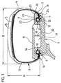
- Fig. 1 shows a vehicle wheel with pneumatic vehicle tires 3 and rim 1 with a ratio of maximum height H to maximum width B of the pneumatic vehicle tire H / B ⁇ 0.6.
- the Pneumatic vehicle tire 3 has a circumference of the tire and from the left bead area 6 of the pneumatic vehicle tire reaching to the right bead area 6, not shown in detail, Inner layer over which a carcass 4 radial design with, for example, one or two carcass plies is built up.
- the area of the tread is radially outside of the Carcass 4 a belt 5 of known type with, for example, two belt plies made in Rubber-embedded reinforcement, e.g. made of steel cord.
- the belt is enough over the entire circumference of the tire and extends in the axial direction from one tire shoulder area in the other.
- the steel cords run at an acute angle of, for example, 10-30 ° to the circumferential direction. Radially outside the belt layers, it is conceivable to have a belt bandage, not shown strength members running essentially to the circumferential direction, for example made of Nylon to wind up.
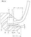
- the one-piece rim 1 is provided with one on each of its two axial end faces Ring chamber 10 arranged concentrically to the rim with a radially inner one Annular chamber wall 20, an axially inner annular chamber wall 21, a radially outer one Annular chamber wall 22 and an axially outer annular chamber wall 23 are formed in one piece.
- the annular chamber wall 23 delimits the radially inwardly directed rim flange 2. Axially to the inside between the rim flange 2 and the radially inner annular chamber wall 20 is one annular through opening 24 formed axially from the outside towards the annular chamber.
- the Rim flange 2 is on its radially inward side 25 from axially inward to axially flared on the outside and curved on its end face 26.
- a one piece Emergency running support ring 11 with an axial width E extends - as can be seen in FIG. 5 - concentric to the rim within the tire axially from the axial rim edge in the axial Direction to at least the center of the rim width F..
- the emergency run support ring 11 is radial formed on the outside with an emergency running surface 14.
- the emergency running surface 14 is profiled with in In the axial direction, circumferential ribs 34 arranged equidistant from one another Mistake.
- the support ring is supported in the axial region of the position of the annular chamber 10 the radially outer side of the rim flange 2, which the rim on the vehicle Limited on the outside of the vehicle, in the radial direction.
- the runflat surface extends one embodiment so far in the axial direction that the belt of the Belt edge made with 50 to 100% of its belt width W, for example 80%, axially the Emergency running surface covered.
- the vehicle pneumatic tire 3 engages with its lower side wall regions 16 horns 2 extending radially inward.
- the curvature of the end face 6 of the horn corresponds to that desired tire contour in the area of the horn.
- the bead area 6 is in each case with The bulge-shaped thickening 7 formed on the inside of the tire.
- the bead is with an elastic stretchy and elastic embedded in the carcass ply end compressible core 8 formed.
- the bead area fills 6 with positive locking to the axially inner annular chamber wall 21 and the radially outer Annulus 22 and the axially outer annulus 23 about 1/2 to 2/3 of Annulus.
- a filler ring 12 is radially form-fitting radially inside the bead to the bead area 6 radially outwards and radially inwards to the radially inner one Annular chamber wall 20 is formed, which extends in the axial direction from the annular chamber wall 10 over the entire axial extent of the bead region 6 through the ring opening 24 extends axially outward therethrough.
- the filler ring 12 is over the entire axial Extension area of the annular chamber and thus of the bead on its radially outer Shell cylindrical and axially outside the annular chamber parallel to the radially inner Side of the rim flange 25 flared.
- the filler ring 12 extends in the axial direction up to the axial position of the end face 26 of the rim flange.
- the bead is in the embodiment according to FIG. 1 with positive locking radially outward, axially inward and axially outward to the closed Annular chamber walls 22, 23, 21 and through the radial positive connection to the filler ring 12, the is in turn designed in a radial positive connection to the closed annular chamber wall 20, also to the annular chamber wall 20 in radial positive engagement.
- the annular chamber is completely filled with bead and filler ring.
- the lower side wall region 16 stands with the radially inner conical one Rim flange side 25 and with the correspondingly designed conical outer Mantle surface of the filler ring 12 also in the axial extent of the rim flange in full contact.
- the tire side wall lies in the region of the end face 26 of the horn 2 of the rim only under tension.
- the side wall area available for this purpose for the flexible curvature of the side wall extends from the shoulder area of the tread to the entire curved area of the end face 26. In the event of strong impacts, the tire side wall 9 lifts off in the area of the end face 26, forming a gap between the end face 26 and the tire side wall .
- the runflat support ring 11 extends over the entire circumferential area of the tire. At Sudden loss of pressure, the tire rests with its tread area on the Emergency tread 14 from. Premature destruction and detachment of the tire are avoided.
- the emergency run support ring 11 is made of elastic material - for example rubber or rubber-like plastic - formed into a layer 33 of parallel to each other arranged, tensile strength members is embedded.
- the elastic material of the Run-flat support ring is softer than the rubber material of the tread of the pneumatic vehicle tire.
- a full silica mixture of known type such as that made of solid rubber manufactured industrial tires is used.
- the strength members are monofilaments or cords made of tensile material, such as for Manufacture of tire belts is used.
- the strength members Monofilaments or cords made of aramid, steel or other suitable metallic or textile material.
- the strength members extend over the entire circumference of the Emergency running support ring at an angle between 0 ° and 30 ° to the circumferential direction.
- the layer 33 extends over a width G, which at least extends in the axial direction extends between the axial position of the belt edge and the center of the belt width.
- the Rim 1 is integral with a peripheral rib in the area of the center of the rim in its drop center 32 formed, which extends radially at least as far as the emergency running support body supporting rim flange on its radial outside.
- the emergency running support body 11 is supported with its left-hand side shown in FIG. 5 on the radial, cylindrical shape Outside of the left rim flange 2 and with its right side on the radial Outside of the circumferential rib 32 from friction
- the emergency running support ring radially on the position of Strength members a wide layer of strength members in one of the above Training opportunities embedded.
- the strength members of one layer are parallel or - if necessary to increase stiffness - not parallel to that of the first layer arranged. It can be useful to determine the direction of the slope of the reinforcement axial direction in one position opposite to the direction of the slope of the Form strength members of the other layer. It is the same in others Executions possible on the second layer one or more further layers of Embedding strength members in the support ring.
- FIG. 2a shows an enlarged detailed view of the outer edge region of the rim of FIG Fig. 1.
- Figure 2a it can be seen that the inside 25 of the rim flange of the Annular chamber wall 23 starting from the inclusion of an angle ⁇ to the wheel axis axially externally expanded up to the curved end face 26 of the rim flange 2.
- the radial outer lateral surface of the filling ring 12 is starting from the annular chamber wall 21 over the entire axial extent of the annular chamber to the annular chamber wall 23 and in an axial extension from the annular chamber up to an axial distance b
- Annular chamber wall 23 is cylindrical.
- the radially outer surface of the filler ring 12 is axial Direction to the outside parallel to the inside 25 of the rim flange also included of the angle ⁇ to the wheel axis axially outwardly flared.
- the Filling ring like the rim flange, still extends a distance a from Annular chamber wall 23 axially outwards.
- the filler ring 12 is axially displaceable on a cylindrical bearing surface 30 of the rim. Inside the ring chamber forms the Bearing surface 30, the radially inner annular chamber wall 20. The extends axially outward Bearing surface 30 to a distance d from the annular chamber wall 23.
- Axially outside of Distance d is the filler ring thickened radially inward to a shoulder and lies with this on a correspondingly trained shoulder of the rim.
- the distances a, b, d are chosen such that a is greater than d and d is greater than b.
- the angle ⁇ lies between 2 and 20 °. In the illustrated embodiment, it is approximately 10 °. In this way enclose the bead with its thickening 7 and the subsequent lower one Sidewall region 16 between the inner rim flange 25 and the filler ring the rim flange positively guided, whereby the anchoring of the tire in the rim is additionally secured.
- the filler ring is made of rubber or an elastic plastic with self-locking Surface trained. It is also conceivable to make the filler ring from a non-elastic Manufacture plastic or metal. If necessary in individual cases, it is also possible to Filling ring in the assembled state with its shoulder on the corresponding shoulder of the Also fix the rim axially, for example by screwing.
- the Bearing surface 30 extends axially to a distance c, which is less than or equal to that Distance a is from the annular chamber side wall 23 to the outside.
- the radially outer The lateral surface of the filling ring is from the axial position of the ring chamber side wall 23 also conical at the pitch angle ⁇ .
- the radial interior The outer surface of the filler ring is just like the correspondingly designed bearing surface 30 from an axial position at a distance c from the ring chamber side wall to the outside axially also conically expanded at an angle ⁇ to the wheel axis.
- the distance is c smaller a. Due to this conical design, the elastic filling ring is mounted in its Position additionally secured by axial positive locking.
- Fig2c is a filling ring as shown in Fig2b, but in the elastic rubber or Plastic material embedded essentially extending in the circumferential direction
- Strength member 17 contains.
- the strength members give the filler ring additional hold of the bearing surface 30.
- the strength members 17 can be arranged in a number of side by side Be circumferential wound tensile strength members.
- Another version is one or more strength members arranged side by side continuously helical around the axis of the filler ring from one axial end to the other axial end of the filler ring wrapped.
- the distances between the adjacent windings are equidistant. So far useful to achieve an even more secure fixation of the filling ring on the bearing surface 30, the distances can also be chosen differently.
- the strength members are Monofilaments or multifilaments made of steel. In another version they are Reinforcing textile monofilaments or multifilaments. It is also conceivable that To form reinforcement 17 from strips of fabric. The reinforcement of the filler ring 12 by strength members in the manner described is also in the embodiment of Fig.2a possible.
- Fig. 2d shows a further alternative embodiment, in which the filler ring also outside the Annular chamber is cylindrical.
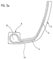
- the bead core 8 is made by embedding the core 8 into the carcass 4 by turning the carcass 4 around the core from the inside out, or as shown in the embodiment of Fig. 3b, anchored from the outside inwards.
- the Carcass 4 is tightly wrapped around core 8 and the cover 4 'is the same as in the other Embodiment of the envelope 4 '' following the core 8 in direct contact to the main part of the carcass.
- the core 8 is droplet-shaped to the point of contact between Cover and body of the carcass are tapered.
- To form the core 8 is an elastic rubber material with a Shore A hardness of 80 to 100, preferably 85 to 90 - in the exemplary embodiment of FIG.
- the core is extrusion by injection molding or comparatively known Techniques made.
- the rubber material of the bead is chosen so that the bead has the stated elongation and compression properties in the circumferential direction having.
- abrasion between the rim flange and the lower side wall becomes undesirably large it is also possible, as shown by way of example in FIGS. 1 and 2a, between the rim flange and bead an additional strip 13 of abrasion-resistant material, for example of to form abrasion-resistant rubber or plastic.
- the abrasion-resistant strip can go right into the Ring chamber and be folded over there around the bead.
- the emergency running support surfaces 14 have one maximum outer diameter Dmax, the two rim flanges a minimum Inner diameter Dmin.
- the tire bead is in Fig.4a in the unexpanded and un-compressed state.
- Its outer diameter Dwa corresponds to the diameter of the radially outer annular chamber wall 22 and thus the outer diameter of the bead Dsa in its sitting position in the ring chamber.
- Its inner diameter Dwi corresponds to that Diameter of the radially outer circumferential surface of the filling ring 12 in the annular chamber and thus the inner diameter of the bead Dsi in its seating position in the annular chamber.
- Dmax is greater than Dsa
- Dsa is greater than Dsk
- Dsk is greater than Dmin
- Dmin is greater than Dsi.
- the emergency run support ring 11 is first concentrically in its sitting position on the Pushed and attached to the rim. Then the tire 3 is concentric to the rim on the Rim in the figures brought axially from the right. The left bulge turns against the elastic restoring forces of the bead stretched so far in the circumferential direction that the Inner diameter Dwi of the bead is larger than the maximum outer diameter Dmax Emergency running surfaces. Then, as shown in FIG. 4b, the tire 3 continues moved concentrically to the rim axially towards the rim, the left bead being retained its stretched condition with play to the emergency running support surfaces 14 axially over the rim and the support body is pushed.
- both beads are now against the elastic restoring forces in their circumferential length so far that the Outer diameter Dwa of the bead is smaller than the minimum rim flange diameter
- the beads are axially into the with play to the rim flange respective ring chamber introduced.
- the beads are set back in their circumferential length so far that they again assume unstretched and uncompressed condition.
- Dwi corresponds again Dsi
- Dwk also correspond to the middle one again Diameter Dsk of the core in its seating position in the ring chamber.
- the beads sit unstretched and undersized in the ring chamber. This state is shown in Fig.4d. As shown in FIG.
- a filler ring 12 is now between each axially outside lower sidewall region 16 of the tire and bearing surface 30 axially inserted so far that the annular chamber is completely filled by the bead and filler ring.
- the complete one Form-fit between the one-piece annular chamber and the bead is established.
- the filling ring is first removed axially outwards. After that the beads are compressed so far that they play with the rim flange from the ring chamber can be pulled. After resetting the circumferential length, a bead becomes so far stretched that it can be pulled axially from the rim with play to the emergency running support surfaces can.
- the diameter Dmax is, for example, 1.2 times larger than the inside diameter Dsi of the bead in the sitting position in the annular chamber and the minimum rim flange diameter is 1.025 times smaller than that Outside diameter Dsa of the bead in the sitting position in the ring chamber.
- Rubber material of the bead becomes a rubber material with an elasticity and with a compressibility chosen, such a stretching and compressing the bead in Circumferential direction allow the bead over the emergency support surface 14 and in the Annular chamber can be moved axially with play.
- a well-known Rubber material is used, the circumferential expansion of the bead by 25% and one Enable circumferential compression by 2.7%.
- the emergency support surfaces can also have a larger or smaller maximum Outside diameter Dmax according to the individually to be set Run-flat properties of a tire.
- the maximum diameter Dmax Run-flat support surfaces are ideally a factor of 1.1 to 1.2 for standard tires larger than the inner ring diameter Dsi of the bead core when the Vehicle wheel. In special cases, however, it can also be by a factor between 1.05 and 1.3 larger than the inner ring diameter Dsi of the bead core in the assembled state of the vehicle wheel.
- a rubber material is used as the rubber material of the bead with an extensibility and with a compressibility chosen, such an elongation and circumferentially upsetting the bead allow the bead to pass over the Emergency running support surface 14 and can be moved axially with play in the annular chamber.
- the bead which is not stretched when the vehicle wheel is assembled and is not compressed, designed such that it has an extensibility between 10 and 20% and a compressibility of 2.5 to 3.5% for standard tires and one in special cases Elasticity between 5 and 30% and compressibility between 1 and 5% having.
- the support body 35 is made of rubber, plastic or sheet metal in Lightweight construction or from another suitable material with low weight, with high radial compressive strength, high fatigue strength and good temperature stability formed and extends radially at least as far as the emergency running support body supporting rim flange extends radially on its radial outside. On its radial Outside it is cylindrical. It has a structure with several - eg with 3 - in Axial direction adjacent annular hollow chambers 36,37,38.
- the Emergency running support ring 11 is supported with its left side shown in FIG. 6 on the radial side Outside of the left rim flange 2 and with its right side on the radial Outside of the circumferential rib 32 from friction.
- the support ring is in the above embodiments on the Rim flange 2 and mounted on the support body 35 or on the peripheral rib 32.
- the Friction can occur, for example, by designing the emergency running support body with a press fit to the radial outside of the rim flange and the support body 35 or the peripheral rib 32 be generated
- the emergency run support ring also positively on the radial outside of the To attach rim flange 1.
- the emergency run support ring also positively on the radial outside of the To attach rim flange 1.
- FIG formed a circumferential groove 39 radially outside of the rim flange 1, into which form-fitting a circumferential rib correspondingly designed on the emergency running support ring 40 when the emergency support ring is pushed axially into its emergency support position engages with a snap.
- FIG. 8a and 8b are exemplary embodiments of the peripheral rib 40 and the Circumferential groove 39 shown.
- 8a, circumferential rib 40 and circumferential groove 39 have one trapezoidal cross-section
- FIG. 8b circumferential rib 40 and circumferential groove 39 have a triangular cross-section.
- Circumferential rib 40 and circumferential groove 39 have a rounded cross section.
- Fig. 7 shows an embodiment of the invention in which the rim with a flat bed 41st is formed, which extends radially at least as far with its radial surface, how the rim flange supporting the emergency running ring is radial on its radial outside extends.
- Left shoulder 42 the outer diameter is as large as the outer diameter of the radial surface of the left rim flange supporting the emergency run support body.
- the radially inner side of the Run-flat support ring is this outer contour of the rim flange and the flat bed Correspondingly designed so that the emergency support ring 11 from the left to the rim Assembly can be pushed on until it is on the inside of the emergency support ring trained stop shoulder in stop with the corresponding stop 42 of the Rim comes.
- the emergency running support ring 11 is supported with its left hand one shown in FIG. 7 Side on the radial outside of the left rim flange 2 and then on the radial outside of the flat bed 41 from friction.
- the emergency run support ring can be fixed on its axial Outside with a radially inward only over part of the circumference Directional nose 43 are provided, the axial sliding of the emergency support ring engages in a corresponding axial groove in the rim surface and the support ring in Circumferential direction.
- FIG. 9 shows an embodiment of a vehicle wheel according to FIG. 1, but with two Run-flat support rings.
- a one-piece emergency running support ring 11 with an axial width E extends axially from an axial concentric to the rim within the tire Rim edge in the axial direction to the center of the rims, but ends before reaching the center Rim width F.
- Each emergency run support ring 11 is radially outer with an emergency run surface 14 educated.
- the emergency running surface 14 is profiled with one another in the axial direction Equidistantly arranged circumferential ribs 34 are provided.
- Each support ring supports itself in the axial region of the position of the annular chamber 10 on the radially outer side of the associated rim flange 2, the rim on the vehicle to the outside of the vehicle limited, in the radial direction.
- the emergency running surface extends in one Execution so far in the axial direction that the belt from the belt edge with 10 to 40% of its belt width W, for example 30%, axially covers the emergency running surface.
- the profile ribs 34 of the support surface are in FIGS. 1 to 9 either not at all or shown with a substantially rectangular cross-sectional contour.
- Figures 10a and 10b show a cross section of the support ring in a sectional plane in which the axis of the Support ring is.
- the support ring 11 is on its radially outer surface with Circumferential direction of the support ring extending along the circumference side by side Equidistantly arranged parallel profile grooves 44, each between two adjacent profile grooves 44 parallel to them in the circumferential direction of the support ring Profile rib 34 extending over the circumference is formed.
- Profilrillengrund 47 rises the side wall 45 of the profile rib with inclusion an inclination angle ⁇ that changes in the radial direction with respect to the radial in the radial direction Direction outwards and then into the convexly curved radial outside 46 of the To pass profile rib 34.
- An alternative contour course is the example of one wide support element shown in Fig.11. There the contour course corresponds axially Direction of semi-circles with the same radius for the convex semicircular curvature and for the concave semicircular curvature.
- Fig. 12 a, b, c shows the course of the example of an embodiment with the contour of Fig. 11 Profile grooves and profile ribs in the circumferential direction.
- FIGS. 12b and 12c Sectional view of the radial top view of the support ring shown in Fig.12a.
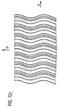
- the profile ribs and profile grooves of the support body are rectilinear in the circumferential direction running, shown in a different embodiment in FIG. 12c running in a wave shape.
- the Waveform is with equal amplitudes to the circumferential direction and along the circumference constant wavelength.
- webs 53 in are transverse to the profile grooves the profile grooves formed, each in a profile groove 44 from an adjacent Profile rib 34 extend to the other profile rib 34 and thus the two profile ribs 34 connect with each other and tie stiffening.
- the webs 53 extend into the Profile grooves above the base of the groove in the radial direction up to half the height h radial extension of the profile ribs 34 over the bottom of the profile groove.
- the webs 53 two Adjacent Rofilrillen are arranged offset to one another in the circumferential direction.
- the density of the profile ribs is Support element, which are each enclosed by two adjacent, profile grooves, in unloaded state of the support ring in the direction perpendicular to the profile rib course 0.4 to 1.5 ribs / cm.
- each profile rib of the support element is in Direction perpendicular to the profile rib course so that it extends from the a tread block member in this width direction of the tread Pneumatic vehicle tire to support the support element is designed in emergency running, deviates. This can be seen, for example, in FIG. 11, in which the Tread is also shown.
- the width of each profile rib of the support element in the direction perpendicular to the profile rib course measured from inflection point to inflection point is preferably less than half Extension of a tread block element in this direction of the tread Pneumatic vehicle tire to support it in the emergency or puncture run the support element is trained.
- the length h is the maximum radial Extension of the profile rib in the unloaded state of the support element starting from Groove base of the adjacent grooves up to the maximum radial extension of the profile rib in the Range between 1/3 and 2/3 of the radial extent T of the annular support body measured from its radial inside at the same axial position and the maximum radial extension of the profile rib is formed. This is for example in Fig. 11 shown.
Landscapes
- Engineering & Computer Science (AREA)
- Mechanical Engineering (AREA)
- Tires In General (AREA)
Abstract
Description
Die Erfindung betrifft einen ringförmigen Stützkörper zum Stützen der Lauffläche eines Fahrzeugluftreifens in einem Fahrzeugrad im Notlauf bzw im Pannenlauf des Fahrzeugrades durch Abstützen des Laufstreifens auf der radialen Außenfläche des ringförmigen Stützkörpers sowie ein Fahrzeugrad mit einem derartigen Stützring.The invention relates to an annular support body for supporting the tread Pneumatic vehicle tire in a vehicle wheel in emergency running or in the flat running of the vehicle wheel by supporting the tread on the radial outer surface of the annular Support body and a vehicle wheel with such a support ring.
Ein ringförmiger Stützkörper zum Stützen der Lauffläche eines Fahrzeugluftreifens in einem
Fahrzeugrad im Notlauf bzw im Pannenlauf eines Fahrzeugrades durch Abstützen des
Laufstreifens auf der radialen Außenfläche des ringförmigen Stützkörpers,
wobei der ringförmige Stützkörper aus elastomerem Material und mit einer Profilierung
ausgebildet ist, die parallele Profilrillen umfaßt, wobei zwischen jeweils zwei benachbarten
Profilrillen eine Profilrippe eingeschlossen ist, die in ihrer Querschnittskontur in einer
Schnittfläche senkrecht zum Rippenverlauf seitlich zu den sie einschließenden Profilrillen
jeweils durch eine Seitenfläche und durch eine die beiden Seitenflächen in ihrem radialen
Endbereich verbindende radiale Außenseite begrenzt wird, ist beispielsweise aus der
EP 0 796 747 A1 bekannt.An annular support body for supporting the tread of a pneumatic vehicle tire in a vehicle wheel in emergency running or in the flat running of a vehicle wheel by supporting the tread on the radial outer surface of the annular support body,
wherein the annular support body is made of elastomeric material and with a profile which comprises parallel profile grooves, a profile rib being enclosed between each two adjacent profile grooves, the cross-sectional contour of which in a sectional area perpendicular to the rib course is to the side of the profile grooves enclosing them, each through a side face and is delimited by a radial outer side connecting the two side surfaces in their radial end region, is known for example from EP 0 796 747 A1.
Für gute Stützwirkung mit hoher Haltbarkeit im Notlauf bzw Pannenlauf ist eine möglichst große stützende Kontaktfläche wünschenswert. Um guten Komfort und gutes Notlauf- bzw Pannenlaufhandling im Notlauf bzw Pannenlauf zu gewährleisten, werden die Stützelemente mit Profilrippen und Profilrillen wie beispielsweise in der EP 0 796 747 A1 dargestellt ausgebildet.For a good support effect with high durability in emergency running or breakdown run one is possible large supporting contact surface desirable. For good comfort and good emergency running or The support elements are used to ensure breakdown running handling in emergency running or breakdown run with profile ribs and profile grooves as shown for example in EP 0 796 747 A1 educated.
Die Querschnittskontur in einer Schnittfläche senkrecht zum Rippenverlauf dieser Profilrippen ist im wesentlichen rechteckig. Die Seitenflächen erstrecken sich geradlinig in radialer Richtung nach außen. Die radiale Außenseite dieser jeweils zwischen zwei Profilrillen angeordneten Profilrippen bilden jeweils zylindrische Mantelfächen, so daß im Not- bzw Pannenlauf im Moment des Berührkontakts des Stützkörpers mit der Lauffläche die Lauffläche unmittelbar auf der gesamten Breite der radialen Außenseite der einzelnen Profilrippe aufliegt und gestützt wird. Hierdurch wird ― wie für gute Haltbarkeitseignung gewünscht - eine große Stützfläche im Notlauf bzw Pannenlauf erzielt. Die Kontur der Profilrippe entspricht bei den bekannten Stützkörpern im wesentlichen der Kontur von Profilrippen im Laufstreifen eines Fahrzeugluftreifens, bei der die Profilrippen zur Erzielung guter Bodenhaftung eine im wesentlichen zylindrische radiale Außenfläche aufweisen.The cross-sectional contour in a cut surface perpendicular to the course of the ribs Profile ribs are essentially rectangular. The side surfaces extend straight in radial direction outwards. The radial outside of this each between two Profile grooves arranged profile ribs each form cylindrical surfaces, so that in Emergency or breakdown run at the moment of contact of the support body with the tread the tread immediately over the entire width of the radial outside of the individual Profile rib rests and is supported. This will - as for good durability suitability desired - a large support surface in emergency run or breakdown run achieved. The contour of the Profile rib corresponds substantially to the contour of the known support bodies Profile ribs in the tread of a pneumatic vehicle tire, in which the profile ribs are used to achieve this good ground grip have a substantially cylindrical radial outer surface.
Erfordernisse - wie beispielsweise Traktion, Nassgriff u.a. - wie sie von Mischungen für den Laufstreifen gefordert werden, werden für die Notlaufstützfläche nicht gefordert. Bei Notlaufstützkörpern werden aufgrund der abweichenden Anforderungen an die Notlaufstützfläche gegenüber der Lauffläche des Fahrzeugluftreifens in der Regel weichere Gummimischungen bevorzugt, die besonderen Komfort im Notlauf ermöglichen sollen, abriebfest sind und nur geringen Wärmeaufbau ermöglichen sollen.Requirements - such as traction, wet grip, etc. - as from mixtures for the Treads are required for the emergency running surface. At Emergency support bodies are due to the different requirements for the Run-flat support surface is generally softer than the tread of the pneumatic vehicle tire Preferred rubber compounds, which should enable special comfort in emergency running, are abrasion-resistant and should only allow low heat build-up.
Im Not- bzw Pannenlauf unterliegen die Profilrippen starken Wechselbeanspruchungen, insbesondere Biegebeanspruchungen um ihre Längsachse. Die starken, wechselnden Verbiegungen können dabei bereits nach relativ kurzer Belastungszeit besonders bei weichen Materialien im Profilaufbau zum Ausreißen in den Übergangsbereichen zwischen Seitenwand und radialer Außenseite und im Übergangsbereich der Profilrippen und zwischen Seitenwand und Profilrillengrund führen. Darüberhinaus kann durch die Wechselbiegung in ungewünschtem Maße Wärme im Profil erzeugt. Auch hierdurch kann das Profil frühzeitig zerstört werden. Die Haltbarkeit wird somit trotz großer effektiver Stützfläche reduziert. Die Funktionsfähigkeit eines Fahrzeugrades mit einem derartigen Stützkörper im Notlauf- bzw Pannenlauf kann hierdurch unerwünscht zeitlich stark begrenzt werden.In emergency or breakdown operation, the profile ribs are subject to strong alternating stresses, in particular bending stresses around its longitudinal axis. The strong, changing Bends can occur after a relatively short loading time soft materials in the profile structure to tear in the transition areas between Sidewall and radial outside and in the transition area of the profile ribs and run between the side wall and the profile groove base. In addition, the Alternating bending to an undesired degree generates heat in the profile. This too can the profile will be destroyed early. The durability is therefore more effective despite great Support area reduced. The operability of a vehicle wheel with such a Support body in the emergency run or breakdown run can be undesirably limited in time become.
Der Erfindung liegt die Aufgabe zugrunde in einfacher Weise die Notlauf- bzw Pannenlauffähigkeit eines Ringförmigen Stützkörpers zum Stützen der Lauffläche eines Fahrzeugluftreifens in einem Fahrzeugrad im Notlauf bzw im Pannenlauf des Fahrzeugrades durch Abstützen des Laufstreifens auf der radialen Außenfläche des ringförmigen Stützkörpers gemäß den Merkmalen des Oberbegriffs von Anspruch 1 beim Einsatz im Not- bzw Pannenlauf in einem Fahrzeugrad zu verbessern. The invention is based, in a simple manner, the emergency running or the task Breakdown ability of an annular support body to support the tread of a Pneumatic vehicle tire in a vehicle wheel in emergency running or in the flat running of the vehicle wheel by supporting the tread on the radial outer surface of the annular Support body according to the features of the preamble of claim 1 when used in emergency or Improve breakdown running in a vehicle wheel.
Die Aufgabe wird erfindungsgemäß durch die Ausbildung eines ringförmigen Stützkörpers
zum Stützen der Lauffläche eines Fahrzeugluftreifens in einem Fahrzeugrad im Notlauf bzw
im Pannenlauf des Fahrzeugrades durch Abstützen des Laufstreifens auf der radialen
Außenfläche des ringförmigen Stützkörpers gemäß den Merkmalen von Anspruch 1 bzw
durch ein Fahrzeugrad gemäß den Merkmalen von Anspruch 15
gelöst.The object is achieved by the formation of an annular support body
to support the tread of a pneumatic vehicle tire in a vehicle wheel in emergency running or
in the flat running of the vehicle wheel by supporting the tread on the radial
Outer surface of the annular support body according to the features of claim 1 and
by a vehicle wheel according to the features of
Die Ausbildung der zwischen den Profilrillen angeordneten Profilrippe mit einer im unbelasteten Zustand im Bereich der radialen Außenseite konvex gekrümmten Querschnittskontur bewirkt, daß im Moment des Berührkontakts mit der Lauffläche des Fahrzeugreifens im Notlauf bzw Pannenlauf zunächst nur im wesentlichen linienförmiger Berührkontakt zwischen Profilrippe und Lauffläche auftritt und danach unter der Belastung die Profilrippe zumindest in ihrem äußeren radialen Bereich radial komprimiert wird, wobei die radiale Außenseite aufgeweitet wird, sodaß im Zustand der eigentlichen Stützwirkung eine entsprechend größere effektive Stützfläche zwischen Profilrippen und Lauffläche erzeugt wird. Das verzögerte Auftreten der effektiven Größe der Stützfläche durch Verformung der im unbelasteten Zustand konvexen Profilrippe erhöht zusätzlich den Komfort des Fahrzeugrades im Notlauf bzw Pannenlauf. Darüberhinaus wird die Profilrippe aufgrund der unterschiedlichen radialen Erstreckungen entland des konvexen Krümmungsverlaufs im belasteten Zustand zusätzlich versteift, sodaß die Wechselbelastungen weniger ausgeprägte Verbiegungen der Profilrippe zur Folge hat. Die Wärmeentstehung kann reduziert werden. Die Zerstörunggefahr durch Ausreißen der Profilrippe kann weitgehend verhindert werden. Die Haltbarkeit des Stützkörpers im Notlauf bzw Pannenlauf wird verbessert.The formation of the arranged between the profile grooves profile rib with an in unloaded state in the area of the radial outside convexly curved Cross-sectional contour causes that at the moment of contact with the tread of the Vehicle tire in emergency running or flat running initially only substantially linear Contact occurs between the profile rib and the tread and then under the load the profile rib is radially compressed at least in its outer radial region, wherein the radial outside is widened, so that in the state of the actual support effect a correspondingly larger effective support surface between the profile ribs and the tread is produced. The delayed appearance of the effective size of the support surface due to Deformation of the profile rib, which is convex in the unloaded state, additionally increases the Comfort of the vehicle wheel in emergency running or flat running. In addition, the profile rib due to the different radial extents along the convex Curvature curve additionally stiffened in the loaded state, so that the Alternating loads result in less pronounced bending of the profile rib. The Heat generation can be reduced. The risk of destruction by tearing out the Profile rib can be largely prevented. The durability of the support body in emergency running or breakdown run is improved.
Durch Ausbildung des Stützkörpers gemäß den Merkmalen von Anspruch 2 wird zusätzlich
die Anbindung der Profilrippe an den Rillengrund versteift, sodaß die Gefahr einer
Rißbildung im Übergangsbereich zwischen Profilrippe und Profilrillengrund zuverlässig
minimiert werden kann.By forming the support body according to the features of
Durch Ausbildung des Stützkörpers mit geneigten Seitenwänden der Profilrippen gemäß den
Merkmalen von Anspruch 3 wird die Biegesteifigkeit der Profilrippen zusätzlich erhöht und
die Zerstörungsgefahr kann weiter reduziert werden. By forming the support body with inclined side walls of the profile ribs according to the
Features of
Die Ausbildung gemäß den Merkmalen von Anspruch 4 ermöglicht einen fließenden
Übergang der Konturgebung einer Profilrippe, wodurch die Steifigkeit zusätzlich erhöht
werden kann.The training according to the features of
Bevorzugt, weil besonders steif und rißfest, ist die Ausbildung mit stetigem fließendem
Verlauf aus der Profilrille bis zur nächsten Profilrille gemäß den Merkmalen von Anspruch 5.
Die Ansprüche 6 und 7 beinhalten bevorzugte Ausführungen dieses Verlaufs.Preferred because it is particularly stiff and crack-resistant, is the formation with steady flowing
Course from the profile groove to the next profile groove according to the features of
Bevorzugt ist eine Ausbildung gemäß den merkmalen von Anspruch 8, wobei die Länge der
maximalen radialen Erstreckung der Profilrippe im unbelasteten Zustand des Stützelements
ausgehend vom Rillengrund der benachbarten Rillen bis zur maxialen radialen Erstreckung
der Profilrippe im Bereich zwischen dem halben und dem dritten Teil der radialen
Erstreckung des ringförmigen Stützkörpers gemessen von dessen radialer Innenseite im
Bereich der Profilrippe und der maximalen radiale Erstreckung der Profilrippe ausgebildet ist.Preferred is an embodiment according to the features of
Besonders vorteilhaft ist die Ausbildung gemäß den Merkmalen von Anspruch 9, da
hierdurch die Gefahr gegenseiteiger negativer Beeinflussung der Profilierung vom
Laufstreifen und der des Stützelements im Notlauf bzw Pannenlauf auf die jeweilige
Funktion zuverlässig minimiert werden kann.The training according to the features of
Besonders vorteilhaft ist die Ausbildung gemäß den Merkmalen von Anspruch 10.The embodiment according to the features of
Bevorzugt ist die Ausbildung gemäß den Merkmalen von Anspruch 11, wobei die
Profilrippen, die jeweils von zwei benachbarten Profilrillen eingeschlossen werden, in
Umfangsrichtung des Stützkörpers ausgerichtet sind und sich über den gesamten Umfang
des Stützkörpers erstrecken. Die Ansprüche 12 und 13 stellen bevorzugte Ausführungen
dar. Die Ausbildung der Profilrippen mit einem in Umfangsrichtung periodisch gekrümmten ―
insbesondere wellenförmigen - Verlauf ermöglicht eine zusätzliche Versteifung der
Profilrippen, die eine besonders gute Einstellung der Handlingeigenschaften des
Fahrzeugrades im Notlauf bzw Pannenlauf ermöglichen. Bevorzugt sind die Amplituden
und/oder Frequenz der periodischen Krümmung über den Umfang konstant.Preferred is the formation according to the features of
Die Ausbildung gemäß den Merkmalen von Anspruch 14 ermöglicht eine zusätzliche
Versteifung der Profilrippen durch gegenseitige Anbindung.The training according to the features of
Bevorzugt ist die Ausbildung eines Fahrzeugrades gemäß den Merkmalen von Anspruch 16
zur Erzielung besonders guter Notlaufeigenschaften, da im Notlauf hierdurch Kräfte aus dem
Laufstreifen in gleicher axialer Position in die Felge eingeleitet werden können wie im
Normalbetrieb.The design of a vehicle wheel according to the features of
Die Ausbildung des Fahrzeugrads nach Anspruch 17 ermöglicht in einfacher Weise, daß die
Felgenmantelfläche vollständig zur Ausgestaltung einer Notlaufstützfläche zur Verfügung
steht und der Reifen dennoch zuverlässig und einfach und zwar in der Stirnfläche der Felge
befestigt werden kann. Nach Einführen des Wulstes in die Ringkammer wird der Füllring in
die Ringkammer eingeschoben und der Wulst hierdurch formschlüssig zur Ringkammer
fixiert.The design of the vehicle wheel according to
Bevorzugt ist die Ausbildung eines Fahrzeugrads gemäß den Merkmalen von Anspruch 18. Der in seiner Umfangslänge ― insbesondere elastisch ― veränderbare Wulstkern ermöglicht die Montage des Wulstes durch Bewegung über die radial äußere Mantelfläche der Felge ― insbesondere über die Notlaufstützfläche - mit einem größeren Wulstkerndurchmesser als im befestigten Betriebszustand des Wulstes und zur Bewegung über das Felgenhorn mit einem kleineren Wulstkerndurchmesser als im befestigten Betriebszustand, sodaß die Ausbildung der radial äußeren Mantelfläche der Felge ― insbesondere der Notlaufstützflächen - nicht mehr in Abhängigkeit vom Durchmesser des Wulstkerns im Betriebszustand und vom inneren Felgenhorndurchmesser, sondern in erster Linie nach sonstigen Kriterien ― beispielsweise optimalen Notlaufeigenschaften entsprechend - ausgebildet werden kann. Bevorzugt ist die Ausbildung gemäß den Merkmalen von Anspruch 19. Nach Einführen des Wulstes in die Ringkammer wird der Füllring radial innerhalb des Wulstes axial in die Ringkammer eingeführt, sodaß zwischen radial innerer Ringkammerwand und Füllring, zwischen Füllring und Wulst und zwischen Wulst und radial äußerer Ringkammerwand radialer Formschluß und zumindest zwischen Wulst und dem die axial äußeren Ringkammerwand bildenden Felgenhorn axialer Formschluß hergestellt wird. Während des Fahrzeugradbetriebes besteht sowohl im Normal- als auch im Notlaufbetrieb nach Druckluftverlust ein zuverlässiger Formschluß zumindest nach axial außen und nach radial außen und nach radial innen zwischen einstückiger Ringkammer der Felge und Wulst. Sowohl die wesentlichen axialen als auch die radial auf den Wulst wirkenden Kräfte werden somit unmittelbar in die im Befestigungsbereich einstückige Felge eingeleitet. In das einzige zusätzliche Element, den Füllring, werden auch im Notlaufbetrieb keine wesentlichen axialen Kräfte eingeleitet. Auf diese Weise kann der Wulst sogar im Notlaufbetrieb sicher und zuverlässig seine Position in der Ringkammer beibehalten. Der in seiner Umfangslänge veränderbare Wulst kann somit in einfacher und funktionssicherer Weise sowohl montiert als auch demontiert werden wobei sowohl die Notlaufstüzflächen für den Notlauf optimiert als auch das Felgenhorn hinsichtlich der axialen Stütze für den Wulst und der Wulstkern in seinem Betriebszustand hinsichtlich seiner Eigenschaften im Betriebszustand optimiert werden können. Besonders sicher ist die Krafteinleitung in die Felge, wenn der Wulst über seine ganze axiale Erstreckung nach radial innen vollständig auf dem Füllring aufliegt. Wenn der Wulst und der Füllring die Ringkammer vollständig ausfüllen, wird ein besonders zuverlässiger Formschluss zwischen Wulst und Felge erzielt. Durch Ausbildung des Fahrzeugluftreifens mit elastisch veränderbarer Umfangslänge des Wulstes ist besonders einfach und sicher eine Umfangslängenveränderung von einer ersten Umfangslänge zu individuell entsprechend den jeweiligen Erfordernissen geänderten weiteren Umfangslängen entgegen der Wirkung rückstellender Kräfte und wieder zurück in die erste Umfangslänge unter Ausnützung der rückstellenden Kräfte erzielbar.The design of a vehicle wheel according to the features of claim 18 is preferred. The bead core, which can be changed in its circumferential length - in particular elastically - is possible the assembly of the bead by moving over the radially outer surface of the rim - especially over the emergency running surface - with a larger bead core diameter than in the attached operating state of the bead and for movement over the rim flange a smaller bead core diameter than when fastened, so that the Formation of the radially outer lateral surface of the rim - in particular the Emergency running support surfaces - no longer depending on the diameter of the bead core in the Operating condition and the inner rim flange diameter, but primarily after other criteria - e.g. optimal emergency running properties - can be trained. The training according to the features of is preferred Claim 19. After inserting the bead into the annular chamber, the filler ring becomes radial inserted axially into the annular chamber within the bead, so that between the radially inner Annular chamber wall and filler ring, between filler ring and bead and between bead and radial outer annular chamber wall radial positive locking and at least between the bead and the axially outer ring chamber wall forming rim flange axial positive locking is produced. During vehicle wheel operation there is both normal and emergency operation after loss of compressed air, a reliable positive connection at least to the outside and to the outside radially outwards and radially inwards between the one-piece annular chamber of the rim and Bead. Both the essential axial and the radial forces acting on the bead are thus introduced directly into the one-piece rim in the fastening area. In the only additional element, the filler ring, are not essential even in emergency operation initiated axial forces. In this way, the bead can be secured even in emergency operation and reliably maintain its position in the annular chamber. The one in its circumferential length changeable bead can thus be both assembled and in a simple and reliable manner can also be dismantled whereby both the emergency running support surfaces are optimized for emergency running also the rim flange with regard to the axial support for the bead and the bead core in optimized its operating state with regard to its properties in the operating state can be. The introduction of force into the rim is particularly safe when the bead is over its entire axial extension lies completely radially inward on the filling ring. If the bead and the filler ring completely fill the ring chamber becomes a special one Reliable positive locking between bead and rim achieved. By training the Pneumatic vehicle tire with an elastically variable circumferential length of the bead is special a change in circumferential length from a first circumferential length is simple and safe further circumferential lengths individually changed according to the respective requirements against the action of restoring forces and back to the first circumferential length achievable using the restoring forces.
Bevorzugt ist die Ausbildung gemäß den Merkmalen von Anspruch 20 zur Erzielung
besonders guter Notlaufeigenschaften, da im Notlauf hierdurch Kräfte aus dem Laufstreifen
in gleicher axialer Position in die Felge eingeleitet werden können wie im Normalbetrieb.
Darüberhinaus ist der bei beispielsweise Befahren eines Bordsteins wesentlich
beanspruchte Laufstreifenrandbereich auch im Notlauf bzw im Pannenlauf durch den
Stützkörper gestützt. Die beidseitige Anordnung ermöglicht eine besondere Sicherung beim
in beiden Laufstreifenrandbereichen.The training according to the features of
Eine alternative vorteilhafte Ausbildung zur Erzielung besonders guter Notlaufeigenschaften
ist die Ausbildung gemäß den Merkmalen von Anspruch 21, da im Notlauf hierdurch Kräfte
aus dem Laufstreifen in gleicher axialer Position in die Felge eingeleitet werden können wie
im Normalbetrieb. Darüberhinaus ist der bei beispielsweise Befahren eines Bordsteins
wesentlich beanspruchte Laufstreifenrandbereich auch im Notlauf bzw im Pannenlauf durch
den Stützkörper stützbar und der Laufstreifen über einen sehr weiten Bereich gestützt, so
daß eine große Stützwirkung auch im Kronenbereich der Lauffläche erzielt werden kann.An alternative advantageous training to achieve particularly good emergency running properties
is the training according to the features of
Besonders vorteilhaft ist eine Ausbildung des Fahrzeugrades gemäß den Merkmalen von
Anspruch 22, bei dem der Wulstkern ein im Wulst integriert ausgebildeter Gummikern ist.
Der Gummikern ist einfach herzustellen und kann besonders einfach und zuverlässig im
Wulst verankert werden. Der Wulst kann hierdurch in einfacher, zuverlässiger Weise in
seiner Umfangslänge elastisch dehnbar ausgebildet werden. Für einen besonders sicheren
Sitz ist der Gummikern mit einer Shore -A- Härte aus dem Bereich von 80 bis 100 -
bevorzugt aus dem Bereich zwischen 85 bis 90 ― ausgebildet. A design of the vehicle wheel according to the features of is particularly
Besonders vorteilhaft, weil einfach herzustellen, zu montieren und zu demontieren ist die
Ausbildung gemäß den Merkmalen von Anspruch 23. Durch die zylindriche Ausbildung der
radial äußeren Mantelfläche des Füllrings wird darüberhinaus zusätzlich besonders
zuverlässig ein Einleiten axialer Kräfte vom Wulst in den Füllring verhindert, sodaß die
Verankerung des Wulstes noch zuverlässiger wird.Particularly advantageous because it is easy to manufacture, assemble and disassemble
Training according to the features of
Durch die Ausbildung eines Fahrzeugrades gemäß den Merkmalen von Anspruch 24, bei
dem der größte Außendurchmesser der Notlaufstützflächen um einen Faktor zwischen 1,05
und 1,3 größer als der Innenringdurchmesser des Wulstkerns im montierten Zustand des
Fahrzeugrades beträgt, ermöglicht optimale Notlaufeigenschaften durch besonders großen
Außendurchmesser der Notlaufstützflächen bei Beibehaltung der zur Erzielung guter
Einfederung des Reifens und somit guter Komforteigenschaften optimaler kleiner
Innenringdurchmesser des Wulstkerns. Die Ausbildung eines Fahrzeugrades, bei dem der
größte Außendurchmesser der Notlaufstützflächen um einen Faktor zwischen 1,1 und 1,2
größer als der Innenringdurchmesser des Wulstkerns im montierten Zustand des
Fahrzeugrades beträgt, stellt einen opimale Ausbildungsbereich der
Standardreifendimensionen zur Lösung der Zielkonflikte zwischen gute Notlaufeigenschften
einerseits und Komfort und Gewicht des Fahrzeugrades andererseits dar.By forming a vehicle wheel according to the features of
Die Ausbildung eines Fahrzeugrades, bei dem der Wulstkern eine Dehnbarkeit und/oder Stauchbarkeit von 5 bis 30 % aufweist, ermöglicht eine einfache und zuverlässige Montage trotz optimaler Notlaufeigenschaften durch Ausbildung besonders großer Außendurchmesser der Notlaufstützflächen trotz Beibehaltung der Ausbildung der Erzielung guter Einfederung des Reifens und somit guter Komforteigenschaften durch optimal kleine Innenringdurchmesser des Wulstkerns. Durch einfaches ― insbesondere elastisches - Dehnen und/oder Stauchen des Wulstes wird der Wulst jeweils auf den zur Montage bzw zur Demontage über die Notlaufstützflächen erforderlichen optimalen Durchmesser, auf den zur Montage bzw zur Demontage über das nach innen gerichtete Felgenhorn erforderlichen optimalen Durchmesser und auf den zum sicheren Sitz in der Ringkammer erforderlichen optimalen Durchmesser eingestellt. Die Ausbildung eines Fahrzeugrades, bei dem der Wulstkern eine Dehnbarkeit und/oder Stauchbarkeit von 10 bis 20 % ermöglicht eine einfache und zuverlässige Montage bei opimalem Ausbildungsbereich der Standardreifendimensionen zur Lösung der Zielkonflikte zwischen guten Notlaufeigenschaften einerseits und Komfort und Gewicht des Fahrzeugrades andererseits. The formation of a vehicle wheel in which the bead core has an extensibility and / or Compressibility of 5 to 30% enables simple and reliable installation despite optimal emergency running properties by training particularly large Outside diameter of the emergency support surfaces despite maintaining the achievement of the achievement good tire deflection and thus good comfort properties thanks to the optimally small size Inner ring diameter of the bead core. Through simple - especially elastic - Stretching and / or compressing the bead, the bead is in each case on the for assembly or Disassembly over the emergency running surfaces required optimal diameter to the Assembly or disassembly required using the inward-facing rim flange optimal diameter and on the necessary for a secure fit in the ring chamber optimal diameter set. The formation of a vehicle wheel in which the Bead core allows an extensibility and / or compressibility of 10 to 20% simple and reliable installation with an optimal training area Standard tire dimensions to solve the conflict of goals between good ones Emergency running properties on the one hand and comfort and weight of the vehicle wheel on the other.
Bevorzugt ist die Ausbildung gemäß den Merkmalen von Anspruch 26, wonach der
Wulstkern eine Dehnbarkeit von 5 bis 30 % und eine Stauchbarkeit von 1 bis 5% aufweist
und wonach der Wulstkern insbesondere im montierten Zustand des Fahrzeugrades
ungedehnt und ungestaucht ist. Durch einfaches ― insbesondere elastisches - Dehnen aus
dem ungedehnten und ungestauchten Zustand wird der Wulstkern auf einen zur Montage
bzw Demontage über die Notlaufstützfläche optimal großen Durchmesser gebracht. Durch
einfaches ― insbesondere elastisches ― Stauchen aus dem ungedehnten und ungestauchten
Zustand wird der Wulstkern auf einen zur Montage bzw Demontage über das nach innen
gerichtete Felgenhorn optimal kleinen Durchmesser gebracht. Die Ausbildung eines
Fahrzeugrades, bei dem der Wulstkern eine Dehnbarkeit 10 bis 20 % und eine
Stauchbarkeit von 2,5 bis 3,5 % aufweist, ermöglicht eine einfache und zuverlässige
Montage bei opimalem Ausbildungsbereich der Standardreifendimensionen zur Lösung der
Zielkonflikte zwischen guten Notlaufeigenschaften einerseits und Komfort und Gewicht des
Fahrzeugrades andererseits.Besonders vorteilhaft ist es, wenn der Wulstkern im montierten
Zustand des Fahrzeugrades ungedehnt und ungestaucht ist und somit in Umfangsrichtung
weitgehend frei von in Umfangsrichtung wirkenden inneren Kräften ist. Besonders vorteilhaft
ist hierbei die elastische dehnbare und elastisch stauchbare Ausbildung. Der Wulstkern wird
aus dem ungedehnten und ungestauchten Zustand zur Montage über die
Notlaufstützflächen den elastischen Rückstellkräften entgegenwirkend in Umfangsrichtung
gedehnt. Nach der Montage über die Notlaufstützflächen wird er duch die Rückstellkräfte
wieder in seiner Umfangslänge bis in den ungedehnten und ungestauchten Zustand
verkleinert. Zur Montage über das radial nach innen gerichtete Felgenhorn wird der
Wulstkern aus dem ungedehnten und ungestauchten Zustand den elastischen
Rückstellkräften entgegenwirkend in Umfangsrichtung gestaucht. Nach der Montage über
das Felgenhorn wird er in der Ringkammer duch die Rückstellkräfte wieder in seiner
Umfangslänge bis in den ungedehnten und ungestauchten Zustand vergrößert. In
entsprechenderweise erfolgt die Demontage.Preferred is the training according to the features of
Bevorzugt ist das Fahrzeugrad gemäß den Merkmalen von Anspruch 27 derart ausgebildet, daß die axial äußere Stirnfläche als eine axiale Auflagefläche zur axialen Stütze der unteren Reifenseitenwand ausgebildet ist. Auf diese Weise ist der Reifen bei Kurvenfahrten im unteren Seitenwandbereich zur Erzielung guter Handlingeigenschaften axial gestützt und kann bei besonderen Stoßbelastungen unter Aufhebung der axialen Stützwirkung bis in den unteren Seitenwandbereich zur Erzielung guter Komforteigenschaften einfedern. The vehicle wheel is preferably designed in accordance with the features of claim 27, that the axially outer end face as an axial bearing surface for the axial support of the lower Tire sidewall is formed. In this way, the tire is when cornering axially supported and lower side wall area to achieve good handling properties can with special shock loads while canceling the axial support effect up to Compress the lower side wall area to achieve good comfort properties.
Die Erfindung wird im folgenden anhand der in den Figuren 1 bis 13 dargestellten Ausführungsbeispiele näher erläutert. Hierin zeigen
- Fig. 1
- eine Querschnittsdarstellung eines erfindungsgemäßen Fahrzeugrades mit montiertem Fahrzeugreifen,
- Fig. 2
- Querschnittsdarstellungen von Ausführungsformen des Füllrings,
- Fig. 3
- Querschnittsdarstellungen von Ausführungsformen des Wulstbereichs,
- Fig. 4
- schematische Darstellung zur Erläuterung der Montage und der Demontage,
- Fig. 5
- Querschnittsdarstellung des Fahrzeugrades gemäß Fig.1 mit Aufbau des Notlaufstützrings
- Fig. 6
- Querschnittsdarstellung eines Fahrzeugrades gemäß Fig.1 in zweiter Ausführungsform
- Fig. 7
- Querschnittsdarstellung eines Fahrzeugrades gemäß Fig.1 in dritter Ausführungsform
- Fig. 8
- weitere Ausführungsformen einer formschlüssigen Fixierung des Notlaufstützrings
- Fig. 9
- Querschnittsdarstellung eines Fahrzeugrades gemäß Fig.1 mit alternativer Anordnung des Stützrings
- Fig.10
- erste erfindungsgemäße Ausführungsform der Querschnittskantur der Profilrippen und Profilrillen der radial äußeren Oberfläche des Stützrings
- Fig.11
- zweite erfindungsgemäße Ausführungsform der Profilrippen und Profilrillen der radial äußeren Oberfläche des Stützrings
- Fig.12
- Darstellungen zur Erläuterung des Umfangsverlaufs der Profilrippen und Profilrillen des Stützrings
- Fig.13
- Darstellungen einer Ausführung von Profilrippen und Profilrillen des Stützrings mit Stegen zur Anbindung benachbarter Profilrippen.
- Fig. 1
- 2 shows a cross-sectional illustration of a vehicle wheel according to the invention with a mounted vehicle tire,
- Fig. 2
- Cross-sectional representations of embodiments of the filling ring,
- Fig. 3
- Cross-sectional representations of embodiments of the bead area,
- Fig. 4
- schematic representation to explain the assembly and disassembly,
- Fig. 5
- Cross-sectional view of the vehicle wheel according to Figure 1 with construction of the emergency running support ring
- Fig. 6
- Cross-sectional view of a vehicle wheel according to Figure 1 in the second embodiment
- Fig. 7
- Cross-sectional view of a vehicle wheel according to Figure 1 in a third embodiment
- Fig. 8
- further embodiments of a positive fixation of the emergency running support ring
- Fig. 9
- Cross-sectional view of a vehicle wheel according to Figure 1 with an alternative arrangement of the support ring
- Fig. 10
- first inventive embodiment of the cross-sectional contour of the profile ribs and profile grooves of the radially outer surface of the support ring
- Fig. 11
- second embodiment of the profile ribs and profile grooves of the radially outer surface of the support ring according to the invention
- Fig. 12
- Representations to explain the circumferential course of the profile ribs and profile grooves of the support ring
- Fig. 13
- Representations of an embodiment of profile ribs and profile grooves of the support ring with webs for connecting adjacent profile ribs.
Fig. 1 zeigt ein Fahrzeugrad mit Fahrzeugluftreifen 3 und Felge 1 mit einem Verhältnis von
maximaler Höhe H zu maximaler Breite B des Fahrzeugluftreifens H/B ≤ 0,6. Der
Fahrzeugluftreifen 3 weist eine über den Umfang des Reifens und vom linken Wulstbereich
6 des Fahrzeugluftreifens zum rechten Wulstbereich 6 reichende, nicht näher dargestellte,
Innenschicht auf, über die eine Karkasse 4 radialer Bauart mit beispielsweise einer oder
zwei Karkassenlagen aufgebaut ist. Im Bereich der Lauffläche ist radial außerhalb der
Karkasse 4 ein Gürtel 5 bekannter Bauart mit beispielsweise zwei Gürtellagen aus in
Kautschuk eingebetteten Festigkeitsträgern, z.B. aus Stahlcord, aufgelegt. Der Gürtel reicht
über den gesamten Umfang des Reifens hinweg und erstreckt sich in axialer Richtung von
einem Reifenschulterbereich in den anderen. Fig. 1 shows a vehicle wheel with
Die Stahlcorde verlaufen im spitzen Winkel von beispielsweise 10-30 ° zur Umfangsrichtung. Radial außerhalb der Gürtellagen ist es denkbar, eine nicht dargestellte Gürtelbandage mit im wesentlichen zur Umfangsrichtung verlaufenden Festigkeitsträgern, beispielsweise aus Nylon, aufzuwickeln.The steel cords run at an acute angle of, for example, 10-30 ° to the circumferential direction. Radially outside the belt layers, it is conceivable to have a belt bandage, not shown strength members running essentially to the circumferential direction, for example made of Nylon to wind up.
Radial außerhalb des Gürtels bzw. der Gürtelbandage ist in bekannter Weise ein über den
Umfang des Reifens reichender und sich von Schulterbereich zu Schulterbereich
erstreckender Laufstreifen 15 aus Kautschukmaterial aufgelegt. Im Seitenwandbereich 9 ist
Kautschukmaterial auf die Karkasse 4 aufgelegt. Das Seitenwandkautschukmaterial reicht
vom Schulterbereich bis zum Wulstbereich 6.Radially outside the belt or the belt bandage is in a known manner over the
The circumference of the tire extends from shoulder area to shoulder
Die einstückig ausgebildete Felge 1 ist an ihren beiden axialen Stirnseiten jeweils mit einer
konzentrisch zur Felge angeordneten Ringkammer 10 mit einer radial inneren
Ringkammerwand 20, einer axial inneren Ringkammerwand 21, einer radial äußeren
Ringkammerwand 22 und einer axial äußeren Ringkammerwand 23 einstückig ausgebildet.
Die Ringkammerwand 23 begrenzt das radial nach innen gerichtete Felgenhorn 2. Axial
nach innen zwischen Felgenhorn 2 und radial innerer Ringkammerwand 20 ist eine
ringförmige Durchgangsöffnung 24 von axial außen zur Ringkammer hin ausgebildet. Das
Felgenhorn 2 ist an seiner radial nach innen gerichteten Seite 25 von axial innen nach axial
außen konisch erweitert und an seiner Stirnfläche 26 gekrümmt ausgebildet. Ein einteiliger
Notlaufstützring 11 mit einer axialen Breite E erstreckt sich ― wie in Fig. 5 zu erkennen ist -
konzentrisch zur Felge innerhalb des Reifens axial vom axialen Felgenrand in axialer
Richtung bis wenigstens zur Mitte der Felgenbreite F..Der Notlaufstützring 11 ist radial
außen mit einer Notlauffläche 14 ausgebildet. Die Notlaufoberfläche 14 ist profiliert mit in
axialer Richtung voneinander äquidistant zueinander angeordneten Umfangsrippen 34
versehen. Der Stützring stützt sich im axialen Bereich der Position der Ringkammer 10 auf
der radial äußeren Seite des Felgenhorns 2, das die Felge am Fahrzeug zur
Fahrzeugaußenseite hin begrenzt, in radialer Richtung ab. Die Notlaufoberfläche erstreckt
sich dabei in einer Ausführung soweit in axialer Richtung, daß der Gürtel von der
Gürtelkante aus mit 50 bis 100 % seiner Gürtelbreite W, beispielsweise 80%, axial die
Notlaufoberfläche überdeckt.The one-piece rim 1 is provided with one on each of its two axial end faces
Der Fahrzeugluftreifen 3 umgreift mit seinen unteren Seitenwandbereichen 16 die nach
radial innen erstreckten Hörner 2. Die Krümmung der Stirnfläche 6 des Horns entspricht der
gewünschten Reifenkontur im Bereich des Horns. The vehicle
Am Ende des unteren Seitenwandbereiches 16 ist jeweils der Wulstbereich 6 mit zur
Innenseite des Reifens ausgebildeter wulstartiger Verdickung 7 ausgebildet. Der Wulst ist
mit einem in das Karkassenlagenende eingebetteten elastisch dehnbaren und elastisch
stauchbaren Kern 8 ausgebildet. Im montierten Zustand gemäß Fig. 1 füllt der Wulstbereich
6 unter Formschluß zur axial inneren Ringkammerwand 21 und zur radial äußeren
Ringkammerwand 22 sowie zur axial äußeren Ringkammerwand 23 ca. 1/2 bis 2/3 des
Ringkammerraums. Radial innerhalb des Wulstes ist ein Füllring 12 radial formschlüssig
zum Wulstbereich 6 nach radial außen und nach radial innen zur radial inneren
Ringkammerwand 20 ausgebildet, der sich in axialer Richtung von der Ringkammerwand 10
über die gesamte axiale Erstreckung des Wulstbereichs 6 durch die Ringöffnung 24
hindurch nach axial außen erstreckt. Der Füllring 12 ist über den gesamten axialen
Erstreckungsbereich der Ringkammer und somit des Wulstes an seiner radial äußeren
Mantelfläche zylindrisch und axial außerhalb der Ringkammer parallel zur radial inneren
Seite des Felgenhorns 25 konisch erweitert ausgebildet. In der Ausführung von Fig.1
erstreckt sich der Füllring 12 in axialer Richtung bis hin zur axialen Position der Stirnseite 26
des Felgenhorns. Der Wulst steht in der Ausführung gemäß Fig. 1 unter Formschluß nach
radial außen, nach axial innen und nach axial außen zu den geschlossenen
Ringkammerwänden 22, 23, 21 und durch den radialen Formschluß zum Füllring 12, der
seinerseits in radialem Formschluß zur geschlossenen Ringkammerwand 20 ausgebildet ist,
auch zur Ringkammerwand 20 in radialem Formschluß. Da der Wulst auf seiner gesamten
Oberfläche in formschlüssigem Berührkontakt zur einstückig ausgebildeten Ringkammer
bzw. zum Füllring 12 und der Füllring 12 innerhalb der Ringkammer seinerseits mit seiner
Oberfläche in vollständigem Berührkontakt zu den Ringkammerwänden bzw. zum Wulst
ausgebildet ist, ist die Ringkammer vollständig von Wulst und Füllring ausgefüllt. Darüber
hinaus steht der untere Seitenwandbereich 16 mit der radial inneren konischen
Felgenhornseite 25 und mit der korrespondierend ausgebildeten konischen äußeren
Mantelfläche des Füllrings 12 auch im axialen Erstreckungsbereich des Felgenhorns in
vollständigem Berührkontakt.At the end of the lower
Der vollständige Formschluß des Wulstes zur Felge sichert den Sitz des Reifens auf der Felge während des Fahrens.The complete positive locking of the bead to the rim ensures that the tire sits on the Rim while driving.
Im Bereich der Stirnfläche 26 des Horns 2 der Felge liegt die Reifenseitenwand jeweils
lediglich unter Vorspannung an. The tire side wall lies in the region of the
Bei Auflage eines Umfangselementes des Reifens auf die Straßenoberfläche wirken
resultierende Normalkräfte F zwischen Fahrzeugluftreifen und Straßenoberfläche. Bei der
Eindämpfung dieser Kräfte wirkt auf die Seitenwände 9 des Reifens eine resultierende Kraft
FA, die im wesentlichen in axialer Richtung wirkt und die Seitenwand leicht weiter verkrümmt.
Aufgrund der gewählten Vorspannung zwischen Stirnfläche 26 und Reifen liegt der Reifen in
diesem Normallastfall unter Reduzierung der Vorspannung immer noch an der Stirnfläche 26
an. Bei Kurvenfahrten wird im Bereich der besonders stark belasteten Kurvenaußenseite
aufgrund der eingeleiteten Kräfte die Vorspannung zwischen Stirnfläche 26 und
Reifenseitenwand erhöht. Der Fahrzeugluftreifen 3 wird somit an der besonders stark
belasteten Seite durch das Horn versteift. Ein sicheres Handling ist gewährleistet.When a circumferential element of the tire is placed on the road surface, the resulting normal forces F act between the pneumatic vehicle tire and the road surface. When these forces are damped, a resulting force F A acts on the
Bei starken Stoßwirkungen auf den Reifen wirken stärkere resultierende Kräfte FA auf die
Reifenseitenwände. Diese beulen weiter nach axial außen bei der Eindämpfung aus. Der für
die flexible Krümmung der Seitenwand hierzu zur Verfügung stehende Seitenwandbereich
reicht dabei vom Schulterbereich des Laufstreifens bis über den gesamten gekrümmten
Bereich der Stirnfläche 26. Bei starken Stößen hebt die Reifenseitenwand 9 im Bereich der
Stirnfläche 26 unter Bildung eines Spaltes zwischen Stirnfläche 26 und Reifenseitenwand
ab.With strong impact effects on the tires, stronger resulting forces F A act on the tire sidewalls. These bulge further axially outwards during damping. The side wall area available for this purpose for the flexible curvature of the side wall extends from the shoulder area of the tread to the entire curved area of the
Auch besonders starke auf den Reifen einwirkende Stöße können aufgrund des großen Krümmungsradius R und der sehr langen für die Krümmung zur Verfügung stehenden Bogenlänge der Reifenseitenwand zwischen Reifenschulter und zylindrischer Felgenoberfläche unter geringer Flächenbeanspruchung der gekrümmten Seitenwandoberflächen sicher eingedämpft werden.Particularly strong impacts on the tires can also occur due to the large Radius of curvature R and the very long one available for the curvature Arc length of the tire sidewall between the tire shoulder and the cylindrical one Rim surface under slight surface stress of the curved Side wall surfaces are dampened safely.
Der Notlaufstützring 11 erstreckt sich über den gesamten Umfangsbereich des Reifens. Bei
plötzlichem hinendruckverlust stützt sich der Reifen mit seinem Laufstreifenbereich auf der
Notlauffläche 14 ab. Frühzeitige Zerstörung und Ablösung des Reifens werden vermieden.The
Der Notlaufstützring 11 ist aus elastischem Material - beispielweise aus Gummi oder aus
gummiähnlichem Kunststoff - ausgebildet, in das eine Lage 33 von parallel zueinander
angeordneten, zugfesten Festigkeitsträgern eingebettet ist. Das elastische Material des
Notlaufstützrings ist weicher als das Gummimaterial der Lauffläche des Fahrzeugluftreifens.
Beispielsweise kann eine Vollsilicamischung bekannter Art, wie sie bei den aus Vollgummi
hergestellten Industriereifen Verwendung findet, eingesetzt werden. Die Festigkeitsträger
sind Monofilamente oder Korde aus zugfestem Material, wie es beispielsweise zur
Herstellung von Reifengürteln eingesetzt wird. Beispielsweise sind die Festigkeitsträger
Monofilamente oder Korde aus Aramid, Stahl oder sonstigen geeigneten metallischen oder
textilem Material. Die Festigkeitsträger erstrecken sich über den gesamten Umfang des
Notlaufstützrings unter einem Winkel zwischen 0° und 30° zur Umfangsrichtung.The emergency
Die Lage 33 erstreckt sich über eine Breite G, die sich in axialer Richtung wenigstens
zwischen der axialen Position der Gürtelkante und der Mitte der Gürtelbreite erstreckt. Die
Felge 1 ist im Bereich der Felgenmitte in ihrem Tiefbett einstückig mit einer Umfangsrippe
32 ausgebildet, die sich radial wenigstens so weit erstreckt, wie das den Notlaufstützkörper
stützende Felgenhorn an seiner radialen Außenseite. Der Notlaufstützkörper 11 stützt sich
mit seiner in Fig. 5 dargestellten linken Seite auf der radialen, zylindrich ausgebildeten
Außenseite des linken Felgenhorns 2 und mit seiner rechten Seite auf der radialen
Außenseite der Umfangsrippe 32 reibschlüssig abThe
In einer nicht dargestellten Ausführung ist im Notlaufstützring radial auf der Lage von Festigkeitsträgern eine weiter Lage von Festigkeitsträgern in einer der genannten Ausbildungsmöglichkeiten eingebettet. Die Festigkeitsträger der einen Lage sind parallel oder ― falls zur Erhöhung der Steifigkeit erforderlich - nicht parallel zu denen der ersten Lage angeordnet. Dabei kann es sinnvoll sein, die Steigungsrichtung der Festigkeitsträger zur axialen Richtung in der einen Lage entgegengesetzt zu der der Steigungsrichtung der Festigkeitsträger der anderen Lage auszubilden. In gleicher Weise ist es in weiteren Ausführungen möglich auf die zweite Lage noch eine oder mehrere weiter Lagen von Festigkeitsträgern in denStützring einzubetten.In an embodiment, not shown, is in the emergency running support ring radially on the position of Strength members a wide layer of strength members in one of the above Training opportunities embedded. The strength members of one layer are parallel or - if necessary to increase stiffness - not parallel to that of the first layer arranged. It can be useful to determine the direction of the slope of the reinforcement axial direction in one position opposite to the direction of the slope of the Form strength members of the other layer. It is the same in others Executions possible on the second layer one or more further layers of Embedding strength members in the support ring.
Fig. 2a zeigt eine vergrößerte Detaildarstellung des äußeren Randbereichs der Felge von
Fig.1. In Fig.2a ist erkennbar, daß sich die Innenseite 25 des Felgenhorns von der
Ringkammerwand 23 ausgehend unter Einschluß eines Winkels α zur Radachse nach axial
außen hin bis zur gekrümmten Stirnfläche 26 des Felgenhorns 2 konisch erweitert. Die radial
äußere Mantelfläche des Füllrings 12 ist von der Ringkammerwand 21 ausgehend über den
gesamten axialen Erstreckungsbereich der Ringkammer hinweg bis zur Ringkammerwand
23 und in axialer Verlängerung aus der Ringkammer bis zu einem axialen Abstand b zur
Ringkammerwand 23 zylindrisch ausgebildet. Ausgehend von einer Kreislinie im Abstand b
zur Ringkammerwand 23 ist die radial äußere Mantelfläche des Füllrings 12 in axialer
Richtung nach außen parallel zur Innenseite 25 des Felgenhorns ebenfalls unter Einschluß
des Winkels α zur Radachse nach axial außen hin konisch erweitert ausgebildet. Der
Füllring erstreckt sich ebenso wie das Felgenhorn noch über einen Abstand a von der
Ringkammerwand 23 axial nach außen. Der Füllring 12 ist axial verschiebbar auf einer
zylindrischen Lagerfläche 30 der Felge gelagert. Im Innern der Ringkammer bildet die
Lagerfläche 30 die radial innere Ringkammerwand 20. Nach axial außen erstreckt sich die
Lagerfläche 30 bis in einen Abstand d von der Ringkammerwand 23. Axial außerhalb des
Abstandes d ist der Füllring nach radial innen zu einer Schulter verdickt ausgebildet und liegt
mit dieser an einer korrespondierend ausgebildeten Schulter der Felge an. Die Abstände
a,b,d sind so gewählt, daß a größer als d und d größer als b ist. Der Winkel α liegt zwischen
2 und 20 °. Im gezeichneten Ausführungsbeispiel liegt er bei ca. 10°. Auf diese Weise
umschließen der Wulst mit seiner Verdickung 7 und der sich anschließende untere
Seitenwandbereich 16 zwischen innerer Felgenhornfläche 25 und Füllring das Felgenhorn
zwangsgeführt, wodurch die Verankerung des Reifens in der Felge zusätzlich gesichert wird.2a shows an enlarged detailed view of the outer edge region of the rim of FIG
Fig. 1. In Figure 2a it can be seen that the inside 25 of the rim flange of the
Der Füllring ist aus Gummi oder aus einem elastischen Kunststoff mit selbsthemmender Oberfläche ausgebildet. Es ist auch denkbar, den Füllring aus einem nichtelastischen Kunststoff oder Metall herzustellen. Soweit im Einzelfall erforderlich, ist es auch möglich, den Füllring im montierten Zustand mit seiner Schulter an der korrespondierenden Schulter der Felge beispielsweise durch Verschraubung zusätzlich axial zu fixieren.The filler ring is made of rubber or an elastic plastic with self-locking Surface trained. It is also conceivable to make the filler ring from a non-elastic Manufacture plastic or metal. If necessary in individual cases, it is also possible to Filling ring in the assembled state with its shoulder on the corresponding shoulder of the Also fix the rim axially, for example by screwing.
In den Fig.2b und 2c sind alternative Ausführungen des Füllrings 12 dargestellt. Die
Lagerfläche 30 erstreckt sich axial bis zu einem Abstand c, der kleiner oder gleich dem
Abstand a ist, von der Ringkammerseitenwand 23 nach außen. Die radial äußere
Mantelfläche des Füllrings ist ab der axialen Position der Ringkammerseitenwand 23
ebenfalls konisch unter dem Steigungswinkel α verlaufend ausgebildet. Die radial Innere
Mantelfläche des Füllrings ist ebenso wie die korrespondierend ausgebildete Lagerfläche 30
ab einer axialen Position im Abstand c von der Ringkammerseitenwand nach axial außen
ebenso unter dem Winkel α zur Radachse konisch erweitert ausgebildet. Der Abstand c ist
kleiner a. Durch diese konische Ausbildung wird der elastische Füllring in seiner montierten
Position zusätzlich durch axialen Formschluß gesichert.2b and 2c show alternative designs of the filling
In Fig2c ist ein Füllring wie in Fig2b dargestellt, der jedoch im elastischen Gummi- oder
Kunststoffmaterial eingebettete im wesentlichen in Umfangsrichtung verlaufende
Festigkeitsträger 17 enthält. Die Festigkeitsträger geben dem Füllring zusätzlichen Halt auf
der Lagerfläche 30. Die Festigkeitsträger 17 können mehrere nebeneinander angeordnete in
Umfangsrichtung gewickelte zugfeste Festigkeitsträger sein. In einer anderen Ausführung ist
ein oder mehrere nebeneinander angeordnete Festigkeitsträger kontinuierlich wendelförmig
um die Achse des Füllrings von einem axialen Ende zum anderen axialen Ende des Füllrings
gewickelt. Die Abstände zwischen den benachbarten Wicklungen sind äquidistant. Soweit
zur Erzielung einer noch sichereren Fixierung des Füllrings auf der Lagerfläche 30 sinnvoll,
können die Abstände auch unterschiedlich gewählt sein. Die Festigkeitsträger sind
Monofilamente oder Multifilamente aus Stahl. In einer anderen Ausführung sind die
Festigkeitsträger textile Monofilamente oder Multifilamente. Es ist auch denkbar die
Festigkeitsträger 17 aus Gewebestreifen auszubilden. Die Verstärkung des Füllrings 12
durch Festigkeitsträger in der beschriebenen Art ist auch beim Ausführungsbeispiel von
Fig.2a möglich.In Fig2c is a filling ring as shown in Fig2b, but in the elastic rubber or
Plastic material embedded essentially extending in the circumferential
Fig. 2d zeigt eine weitere alternative Ausführung, bei der der Füllring auch außerhalb der Ringkammer zylindrisch ausgebildet ist.Fig. 2d shows a further alternative embodiment, in which the filler ring also outside the Annular chamber is cylindrical.
Der Wulstkern 8 wird, wie in den Fig.1,2 und 3a dargestellt ist, durch Einbettung des Kerns 8
in die Karkasse 4 durch Umschlag der Karkasse 4 um den Kern von innen nach außen oder,
wie im Ausführungsbeispiel von Fig. 3b dargestellt ist, von außen nach innen verankert. Die
Karkasse 4 ist eng um den Kern 8 gewickelt und der Umschlag 4' ist ebenso wie im anderen
Ausführungsbeispiel der Umschlag 4'' im Anschluß an den Kern 8 in unmittelbarem Kontakt
zum Hauptteil der Karkasse. Der Kern 8 ist tröpfchenförmig zum Berührungspunkt zwischen
Umschlag und Hauptteil der Karkasse verjüngt ausgebildet. Zur Ausbildung des Kerns 8 wird
ein elastisches Gummimaterial mit einer Shore-A-Härte von 80 bis 100, vorzugsweise 85 bis
90 - im Ausführungsbeispiel von Figur 1 mit einer Shore-A-Härte von 87 ― gewählt, das eine
elastische Dehnbarkeit in Umfangsrichtung des Kerns von 5 bis 30%, für Standard-Reifendimensionen
von 10 bis 20%, und eine elastische Stauchbarkeit von1 bis 5%, für
Standard-Reifendimensionen von 2,5 bis 3,5 Prozent, aufweist.As shown in FIGS. 1, 2 and 3 a, the
Der Kern wird durch Extrusion durch injection moulding oder vergleichsweise bekannte Techniken hergestellt.The core is extrusion by injection molding or comparatively known Techniques made.
Es ist auch denkbar, den Wulst kernlos auszubilden, wobei auch in diesem nichtdargestellten Ausführungsbeispiel das Gummimaterial des Wulstes so gewählt wird, daß der Wulst die genannten Dehnungs- und Stauchungseigenschaften in Umfangsrichtung aufweist.It is also conceivable to design the bead without a core, and also in this not shown embodiment, the rubber material of the bead is chosen so that the bead has the stated elongation and compression properties in the circumferential direction having.
Soweit der Abrieb zwischen Felgenhorn und unterer Seitenwand unerwünscht groß wird, ist
es möglich, wie in Figur 1 und 2a beispielhaft dargestellt, zusätzlich zwischen Felgenhorn
und Wulst einen zusätzlichen Streifen 13 von abriebfestem Material, beispielsweise von
abriebfestem Gummi oder Kunststoff auszubilden. Der abriebfeste Streifen kann bis in die
Ringkammer reichen und dort um den Wulst umgeschlagen sein.To the extent that the abrasion between the rim flange and the lower side wall becomes undesirably large
it is also possible, as shown by way of example in FIGS. 1 and 2a, between the rim flange
and bead an
Anhand der schematischen Darstellungen der Figuren 4a bis 4e wird im Folgenden die
Montage des Reifens auf einer Felge beschrieben. Die Notlaufstützflächen 14 weisen einen
maximalen Außendurchmesser Dmax, die beiden Felgenhörner einen minimalen
Innendurchmesser Dmin auf. Der Reifenwulst ist in Fig.4a im ungedehnten und
ungestauchten Zustand. Sein Außendurchmesser Dwa entspricht dem Durchmesser der
radial äußeren Ringkammerwand 22 und somit dem äußeren Durchmesser des Wulstes Dsa
in dessen Sitzposition in der Ringkammer. Sein Innendurchmesser Dwi entspricht dem
Durchmesser der radial äußeren Mantelfläche des Füllrings 12 in der Ringkammer und
somit dem inneren Durchmesser des Wulstes Dsi in dessen Sitzposition in der Ringkammer.
Der Kern mit einer Dicke d, beispielsweise ist d= 10mm, in radialer Richtung hat in der
radialen Position der halben radialen Dicke einen mittleren Kerndurchmesser Dwk durch die
Reifenachse, der dem mittleren Kerndurchmesser Dsk in der Sitzposition des Wulstes in der
Ringkammer entspricht. Dmax ist größer als Dsa, Dsa ist größer als Dsk, Dsk ist größer als
Dmin, Dmin ist größer als Dsi.Based on the schematic representations of Figures 4a to 4e, the
Mounting the tire on a rim described. The emergency running support surfaces 14 have one
maximum outer diameter Dmax, the two rim flanges a minimum
Inner diameter Dmin. The tire bead is in Fig.4a in the unexpanded and
un-compressed state. Its outer diameter Dwa corresponds to the diameter of the
radially outer
Zur Montage wird zunächst der Notlaufstützring 11 konzentrisch in seine Sitzposition auf der
Felge geschoben und befestigt.. Danach wird der Reifen 3 konzentrisch zur Felge an die
Felge in den Figuren von rechts axial herangeführt. Der linke Wulst wird entgegen der
elastischen Rückstellkräfte des Wulstes in Umfangsrichtung soweit gedehnt, daß der
Innendurchmesser Dwi des Wulstes größer als der maximale Außendurchmesser Dmax der
Notlaufstützflächen ist. Danach wird, wie in Figur 4b dargestellt ist , der Reifen 3 weiter
konzentrisch zur Felge axial zur Felge hinbewegt, wobei der linke Wulst unter Beibehaltung
seines gedehnten Zustandes mit Spiel zu den Notlaufstützflächen 14 axial über die Felge
und den Stützkörper geschoben wird. Sobald der linke Wulst eine Position auf der linken
Seite axial außerhalb des linken Felgenhorns erreicht hat wird der Wulst unter Ausnutzung
der elastischen Rückstellkräfte wieder in seiner Umfangslänge soweit zurückgestellt, daß er
wieder den ungedehnten und ungestauchten Zustand einnimmt. In diesem Zustand
entspricht Dwi wieder Dsi, Dwa wieder Dsa und Dwk entspricht ebenfalls wieder dem
mittleren Durchmesser Dsk des Kerns in dessen Sitzposition in der Ringkammer. Wie durch
die Pfeildarstellung von Fig 4c dargestellt, werden beide Wülste nun entgegen der
elastischen Rückstellkräfte in ihrer Umfangslänge soweit gestaucht, daß der
Außendurchmesser Dwa des Wulstes kleiner als der minimale Felgenhorndurchmesser
Dmin ist.In diesem Zustand werden die Wülste mit Spiel zum Felgenhorn axial in die
jeweilige Ringkammer eingeführt. Unter Ausnutzung der elastischen Rückstellkräfte werden
die Wülste wieder in ihrer Umfangslänge soweit zurückgestellt, daß sie wieder den
ungedehnten und ungestauchten Zustand einnehmen. In diesem Zustand entspricht Dwi
wieder Dsi, Dwa wieder Dsa und Dwk entspricht ebenfalls wieder dem mittleren
Durchmesser Dsk des Kerns in dessen Sitzposition in der Ringkammer. Die Wülste sitzen
ungedehnt und ungestaucht in der Ringkammer. Dieser Zustand ist in Fig.4d dargestellt.
Wie in Fig4e dargestellt ist, wird nun jeweils ein Füllring 12 von axial außen zwischen
unterem Seitenwandbereich 16 des Reifens und Lagerfläche 30 axial soweit eingeführt, daß
die Ringkammer vollständig von Wulst und Füllring ausgefüllt ist. Der vollständige
Formschluß zwischen einstückiger Ringkammer und Wulst ist hergestellt.For assembly, the emergency
Zur Demontage wird entsprechend zunächst der Füllring axial nach außen entfernt. Danach werden die Wülste soweit gestaucht, daß sie mit Spiel zum Felgenhorn aus der Ringkammer gezogen werden können. Nach der Rückstellung der Umfangslänge wird ein Wulst soweit gedehnt, daß er mit Spiel zu den Notlaufstützflächen axial von der Felge gezogen werden kann.For disassembly, the filling ring is first removed axially outwards. After that the beads are compressed so far that they play with the rim flange from the ring chamber can be pulled. After resetting the circumferential length, a bead becomes so far stretched that it can be pulled axially from the rim with play to the emergency running support surfaces can.
Danach kann ― soweit es wünschenswert erscheint ― der Notlaufstützkörper entfernt und/oder gegen einen anderen ausgetauscht werden.After that - as far as it seems desirable - the emergency running support body can be removed and / or exchanged for another.
Es ist auch denkbar, den Reifen zur Montage anstatt ihn axial zu verschieben, zunächst um 90 ° zu drehen und dann zu dehnen und im gedehnten Zustand in radialer Richtung auf die Felge zu schieben, um ihn dort wieder um 90 ° zurückzudrehen, so daß sich die beiden Wülste jeweils axial außerhalb der Felge befinden. Die weitere Montage erfolgt wie oben beschrieben.It is also conceivable to move the tire for assembly instead of moving it axially first Rotate 90 ° and then stretch and in the stretched state in the radial direction on the Slide the rim to turn it back 90 ° there, so that the two The beads are located axially outside the rim. The further assembly is as above described.
Im einem Ausführungsbeispiel ist der Durchmesser Dmax beispielsweise um das 1,2-fache
größer als der Innendurchmesser Dsi des Wulstes in der Sitzposition in der Ringkammer
und der minimale Felgenhorndurchmesser ist um den Faktor 1,025 kleiner als der
Außendurchmesser Dsa des Wulstes in der Sitzposition in der Ringkammer. Als
Gummimaterial des Wulstes wird ein Gummimaterial mit einer Dehnungsfähigkeit und mit
einer Stauchbarkeit gewählt, die ein solches Dehnen und Stauchen des Wulstes in
Umfangsrichtung erlauben, daß der Wulst über die Notlaufstützfläche 14 und in die
Ringkammer mit Spiel axial bewegt werden können. Beispielsweise wird ein bekanntes
Gummimaterial verwendet, das eine Umfangsdehnung des Wulstes um 25% und eine
Umfangsstauchung um 2,7% ermöglichen.In one embodiment, the diameter Dmax is, for example, 1.2 times
larger than the inside diameter Dsi of the bead in the sitting position in the annular chamber
and the minimum rim flange diameter is 1.025 times smaller than that
Outside diameter Dsa of the bead in the sitting position in the ring chamber. As
Rubber material of the bead becomes a rubber material with an elasticity and with
a compressibility chosen, such a stretching and compressing the bead in
Circumferential direction allow the bead over the
Die Notlaufstützflächen können auch mit einem größeren oder kleineren maximalen
Außendurchmesser Dmax entsprechend den individuell einzustellenden
Notlaufeigenschaften eines Reifens ausgebildet sein. Der maximale Durchmesser Dmax der
Notlaufstützflächen ist dabei bei Standardreifen optimalerweise um einen Faktor1,1 bis 1,2
größer als der Innenringdurchmesser Dsi des Wulstkerns im montierten Zustand des
Fahrzeugrades. Er kann in Spezialfällen jedoch auch um einen Faktor zwischen 1,05 und
1,3 größer sein als der Innenringdurchmesser Dsi des Wulstkerns im montierten Zustand
des Fahrzeugrades. Als Gummimaterial des Wulstes wird hierfür jeweils ein Gummimaterial
mit einer Dehnungsfähigkeit und mit einer Stauchbarkeit gewählt, die ein solches Dehnen
und Stauchen des Wulstes in Umfangsrichtung erlauben, daß der Wulst über die
Notlaufstützfläche 14 und in die Ringkammer mit Spiel axial bewegt werden können.
Dementsprechend wird der Wulst, der im montierten Zustand des Fahrzeugrades ungedehnt
und ungestaucht ist, derart ausgebildet, daß er eine Dehnbarkeit zwischen 10 und 20 % und
eine Stauchbarkeit von 2,5 bis 3,5 % bei Standardreifen und in den Spezialfällen eine
Dehnbarkeit zwischen 5 und 30 % und eine Stauchbarkeit zwischen aufweist 1 bis 5%
aufweist.The emergency support surfaces can also have a larger or smaller maximum
Outside diameter Dmax according to the individually to be set
Run-flat properties of a tire. The maximum diameter Dmax
Run-flat support surfaces are ideally a factor of 1.1 to 1.2 for standard tires
larger than the inner ring diameter Dsi of the bead core when the
Vehicle wheel. In special cases, however, it can also be by a factor between 1.05 and
1.3 larger than the inner ring diameter Dsi of the bead core in the assembled state
of the vehicle wheel. For this purpose, a rubber material is used as the rubber material of the bead
with an extensibility and with a compressibility chosen, such an elongation
and circumferentially upsetting the bead allow the bead to pass over the
Emergency running
Es ist auch denkbar nach Einführen des Wulstes in die Ringkammer einen Füllring durch Einpritzen von aushärtbarem Kunststoffmaterial von axial außen durch die Öffnung der Ringkammer einzubringen.It is also conceivable to insert a filler ring after the bead has been introduced into the annular chamber Injection of curable plastic material from the outside through the opening of the Introduce annular chamber.
Fig 6 zeigt ein weiteres Ausführungsbeispiel eines erfindungsgemäßen Fahrzeugrades, bei
dem im Tiefbett 31 der Felge 1 formschlüssig ein zusätzlicher ringförmiger Stützkörper 35
montiert ist. Der Stützkörper 35 ist aus Gummi, Kunststoff oder Metallblech in
Leichtbauweise oder aus einem anderen geeigneten Material mit geringem Gewicht, mit
hoher radialer Druckfestigkeit, hoher Ermüdungsfestigkeit und guter Temperaturstabilität
ausgebildet und erstreckt sich radial wenigstens so weit, wie sich das den Notlaufstützkörper
stützende Felgenhorn an seiner radialen Außenseite radial erstreckt. An seiner radialen
Außenseite ist er zylindrisch ausgebildet. Er weist eine Struktur mit mehreren - z B mit 3 - in
axialer Richtung benachbarten, ringförmigen Hohlkammern 36,37,38 auf. Der
Notlaufstützring 11 stützt sich mit seiner in Fig. 6 dargestellten linken Seite auf der radialen
Außenseite des linken Felgenhorns 2 und mit seiner rechten Seite auf der radialen
Außenseite der Umfangsrippe 32 reibschlüssig ab.6 shows a further exemplary embodiment of a vehicle wheel according to the invention, at
an additional
Der Stützring ist in den oben genannten Ausführungsbeispieln reibschlüssig auf dem
Felgenhorn 2 und auf dem Stützkörper 35 bzw auf der Umfangsrippe 32 gelagert. Der
Reibschluß kann beispielsweise durch Ausbildung des Notlaufstützkörpers mit Preßpassung
zur radialen Außenseite des Felgenhorns und des Stützkörpers 35 bzw der Umfangsrippe 32
erzeugt werdenThe support ring is in the above embodiments on the
Wie am Beispiel von Fig.6 dargestellt, ist es in einer anderen Ausführung auch möglich in
beiden Fällen den Notlaufstützring auch formschlüssig auf der radialen Außenseite des
Felgenhorns 1 zu befestigen. Beispielsweise ist hierzu ― wie in Fig. 6 dargestellt ist ― in der
radialen Außenseite des Felgenhorns 1 eine Umrangsrille 39 ausgebildet, in die
formschlüssig eine korrespondierend hierzu am Notlaufstützring ausgebildete Umfangsrippe
40 beim axialen Aufschieben des Notlaufstützrings in seine Notlaufstützposition
einschnappend eingreift.As shown in the example of Fig. 6, it is also possible in another embodiment in
both cases, the emergency run support ring also positively on the radial outside of the
To attach rim flange 1. For example, as shown in FIG
formed a
In Fig. 8a und 8b sind beispielhaft weitere Ausführungsformen der Umfangsrippe 40 und der
Umfangsrille 39 dargestellt. In Fig.8a weisen Umfangsrippe 40 und Umfangsrille 39 einen
trapezförmigen Querschnitt, in Fig.8b weisen Umfangsrippe 40 und Umfangsrille 39 einen
dreieckförmigen Querschnitt auf. In weiterer nicht dargestellter Ausführungsform weisen
Umfangsrippe 40 und Umfangsrille 39 einen abgerundeten Querschnitt auf. Zum
Formschluß durcheinschnappendes Eingreifen der Umfangsrippe 40 in die
korrespondierende Umfangsrille 39 beim axialen Aufschieben des Notlaufstützrings auf die
Felge kann die Umfansrille 39 auf der radialen Außenseite des Felgenhorns 1 oder
beispielsweise auch auf dem zusätzlichen Stützkörper 35 bzw auf der Umfangsrippe 32
ausgebildet.8a and 8b are exemplary embodiments of the
Fig.7 zeigt ein Ausführungsbeispiel der Erfindung, bei dem die Felge mit flachem Bett 41
ausgebildet ist, das sich mit seiner radialen Oberfläche radial wenigstens so weit erstreckt,
wie sich das den Notlaufstützring stützende Felgenhorn an seiner radialen Außenseite radial
erstreckt. An seiner radialen Außenseite ist es beidseitig einer ringförmigen jeweils
zylindrisch ausgebildet, wobei der Außendurchmesser rechts der Anschlagschulter 42
größer als der links der Anschlagschulter 42 ausgebildet ist. Links der Anschlagschulter 42
ist der Außendurchmesser so groß wie der Außendurchmesser der radialen Oberfläche des
linken, den Notlaufstützkörper stützenden Felgenhorns. Die radial innere Seite des
Notlaufstützrings ist dieser Außenkontur des Felgenhorns und des flachen Bettes
korrespondierend ausgebildet, so daß der Notlaufstützring 11 von links auf die Felge zur
Montage soweit aufgeschoben werden kann, bis die an der Innenseite des Notlaufstützrings
ausgebildete Anschlagschulter in Anschlag mit dem korrespondierenden Anschlag 42 der
Felge kommt. Der Notlaufstützring 11 stützt sich mit seiner in Fig. 7 dargestellten linken
Seite auf der radialen Außenseite des linken Felgenhorns 2 und daran anschließend auf der
radialen Außenseite des Flachbetts 41 reibschlüssig ab.Fig. 7 shows an embodiment of the invention in which the rim with a flat bed 41st
is formed, which extends radially at least as far with its radial surface,
how the rim flange supporting the emergency running ring is radial on its radial outside
extends. On its radial outside it is an annular on both sides
cylindrical, the outer diameter to the right of the stop shoulder 42
is larger than the left of the stop shoulder 42. Left shoulder 42
the outer diameter is as large as the outer diameter of the radial surface of the
left rim flange supporting the emergency run support body. The radially inner side of the
Run-flat support ring is this outer contour of the rim flange and the flat bed
Correspondingly designed so that the
Zur sichereren Fixierung der Umfangsposition kann der Notlaufstützring an seiner axialen Außenseite mit einer nur über eine Teil des Umfangs ausgebildeten nach radial innen gerichteten Nase 43 versehen werden, die beim axialen Aufschieben des Notlaufstützrings in eine korrespondierende Axialnut in der Felgenoberfläche eingreift und den Stützring in Umfangsrichtung festlegt.To secure the circumferential position, the emergency run support ring can be fixed on its axial Outside with a radially inward only over part of the circumference Directional nose 43 are provided, the axial sliding of the emergency support ring engages in a corresponding axial groove in the rim surface and the support ring in Circumferential direction.
Fig. 9 zeigt eine Ausführung eines Fahrzeugrades gemäß Fig.1 jedoch mit zwei
Notlaufstützringen. Jeweils ein einteiliger Notlaufstützring 11 mit einer axialen Breite E
erstreckt sich konzentrisch zur Felge innerhalb des Reifens axial von einem axialen
Felgenrand in axialer Richtung zur Mitte der Felgen, endet jedoch vor Erreichen der Mitte
Felgenbreite F. Jeder Notlaufstützring 11 ist radial außen mit einer Notlauffläche 14
ausgebildet. Die Notlaufoberfläche 14 ist jeweils profiliert mit in axialer Richtung voneinander
äquidistant zueinander angeordneten Umfangsrippen 34 versehen. Jeder Stützring stützt
sich im axialen Bereich der Position der Ringkammer 10 auf der radial äußeren Seite des
zugehörigen Felgenhorns 2, das die Felge am Fahrzeug zur Fahrzeugaußenseite hin
begrenzt, in radialer Richtung ab. Die Notlaufoberfläche erstreckt sich dabei in einer
Ausführung soweit in axialer Richtung, daß der Gürtel von der Gürtelkante aus mit 10 bis
40 % seiner Gürtelbreite W, beispielsweise 30%, axial die Notlaufoberfläche überdeckt.FIG. 9 shows an embodiment of a vehicle wheel according to FIG. 1, but with two
Run-flat support rings. In each case a one-piece emergency running
Zwecks vereinfachter Darstellung sind die Profilrippen 34 der Stützfläche in Fig.1 bis 9
entweder gar nicht oder mit im wesentlichen rechteckiger Querschnittskontur dargestellt.For the purpose of a simplified representation, the
Die Fig. 10 bis 13 zeigen Ausführungsbeispiele der erfindungsgemäßen Profilierungen des radialen Außenbereichs der Stützringe, die sinngemäß bei allen oben genannten Ausführungsbeispielen ausgebildet werden. 10 to 13 show embodiments of the profiles of the invention radial outer area of the support rings, which is analogous to all of the above Embodiments are formed.
Fig.10a zeigt ein Ausführungsbeispiel mit schmalem Stützring, wie er beispielsweise in der
Ausführung von Fig. 9 dargestellt ist, Fig.10b zeigt ein Ausführungsbeispiel mit breitem
Stützring, wie er beispielsweise in den von Fig.1 bis 8 dargestellt ist. Die Fig.10a und 10b
zeigen einen Querschnitt des Stützrings in einer Schnittebene, in der die Achse des
Stützrings liegt. Dabei ist der Stützring 11 an seiner radial äußeren Mantelfläche mit in
Umfangsrichtung des Stützrings sich über den Umfang erstreckende nebeneinander
äquidistant angeordneten parallelen Profilrillen 44 ausgebildet, wobei jeweils zwischen zwei
benachbarten Profilrillen 44 eine zu diesen parallele in Umfangsrichtung des Stützrings sich
über den Umfang erstreckende Profilrippe 34 ausgebildet ist. Vom konkav gekrümmten
Profilrillengrund 47 erhebt sich dabei die Seitenwand 45 der Profilrippe unter Einschluß
eines sich in radialer Richtung verändernden Neigungswinkels ε zur Radialen in radialer
Richtung nach außen um dann in die konvex gekrümmte radiale Außenseite 46 der
Profilrippe 34 überzugehen. Der Konturverlauf von Profilrillengrund 47 einer ersten
Profilrille, erster Seitenwand 45 der Profilrippe, radialer Außenseite 46 der Profilrippe 34,
zweiter Seitenwand 45 der Profilrippe und Profilrillengrund 47 einer zweiten Profilrille zweier
benachbarter Profilrillen, die zwischen sich die Profilrippe einschließen ist beispielsweise,
wie in Fig.10 dargestellt ist, sinusförmig. Ein alternativer Konturverlauf ist am Beispiel eines
breiten Stützelements in Fig.11 dargestellt. Dort entspricht der Konturverlauf in axialer
Richtung aneinander gereihten Halbkreisen mit beispielsweise gleichem Radius für den
konvex verlaufender halbkreisförmiger Krümmungsbereich und für den konkav geformten
halbkreisförmigen Krümmungsverlauf.10a shows an embodiment with a narrow support ring, such as that shown in FIG
9 is shown, Fig.10b shows an embodiment with a wide
Back-up ring, as shown, for example, in FIGS. 1 to 8. Figures 10a and 10b
show a cross section of the support ring in a sectional plane in which the axis of the
Support ring is. The
Fig. 12 a,b,c zeigt am Beispiel einer Ausführung mit der Kontur von Fig. 11 den Verlauf der Profilrillen und Profilrippen in Umfangsrichtung. Dabei ist in Fig.12b und 12c jeweils eine Auschnittsdarstellung der radialen Draufsicht auf den Stützring von Fig.12a dargestellt. In Fig. 12b sind die Profilrippen und Profilrillen des Stützkörpers geradlinig in Umfangsrichtung verlaufend, in Fig.12c in einer anderen Ausführung welllenförmig verlaufend dargestellt. Die Wellenform ist mit gleichen Amplituden zur Umfangsrichtung und über den Umfang mit konstanter Wellenlänge ausgebildet.Fig. 12 a, b, c shows the course of the example of an embodiment with the contour of Fig. 11 Profile grooves and profile ribs in the circumferential direction. There is one in each of FIGS. 12b and 12c Sectional view of the radial top view of the support ring shown in Fig.12a. In 12b, the profile ribs and profile grooves of the support body are rectilinear in the circumferential direction running, shown in a different embodiment in FIG. 12c running in a wave shape. The Waveform is with equal amplitudes to the circumferential direction and along the circumference constant wavelength.
In Fig.13 sind am Beispiel der Ausbildung von Fig.12b quer zu den Profilrillen Stege 53 in
den Profilrillen ausgebildet, die sich jeweils in einer Profilrille 44 von einer angrenzenden
Profilrippe 34 zur anderen Profilrippe 34 erstrecken und somit die beiden Profilrippen 34
miteinander verbinden und versteifend anbinden. Die Stege 53 erstrecken sich in den
Profilrillen über dem Rillengrund in radialer Richtung etwa bis zur halben Höhe h der
radialen Erstreckung der Profilrippen 34 über dem Profilrillengrund. Die Stege 53 zweier
benachbarter Rofilrillen sind in Umfangsrichtung versetzt zueinander angeordnet.In FIG. 13, using the example of the configuration in FIG. 12b,
In den genannten Ausführungsbeispielen beträgt die Dichte der Profilrippen des Stützelements, die jeweils von zwei benachbarter, Profilrillen eingeschlossen werden, im unbelasteten Zustand des Stützrings in Richtung senkrecht zum Profilrippenverlauf 0,4 bis 1,5 Rippen/cm.In the exemplary embodiments mentioned, the density of the profile ribs is Support element, which are each enclosed by two adjacent, profile grooves, in unloaded state of the support ring in the direction perpendicular to the profile rib course 0.4 to 1.5 ribs / cm.
In den genannten Ausführungsbeispielen ist die Breite jeder Profilrippe des Stützelements in Richtung senkrecht zum Profilrippenverlauf so ausgebildet, daß sie von der Erstreckung eines Profilblockelements in dieser Breitenrichtung des Laufstreifens eines Fahrzeugluftreifens zu dessen Abstützung im Notlauf das Stützelement ausgebildet ist, abweicht. Dies ist beispielsweise in Fig.11 zu erkennen, in der zum Vergleich der Laufstreifen mitdargestellt ist. Die Breite jeder Profilrippe des Stützelements in Richtung senkrecht zum Profilrippenverlauf gemessen von Wendepunkt zu Wendepunkt ist vorzugsweise kleiner als die halbe Erstreckung eines Profilblockelements in dieser Richtung des Laufstreifens eines Fahrzeugluftreifens zu dessen Abstützung im Not- bzw Pannenlauf das Stützelement ausgebildet ist.In the exemplary embodiments mentioned, the width of each profile rib of the support element is in Direction perpendicular to the profile rib course so that it extends from the a tread block member in this width direction of the tread Pneumatic vehicle tire to support the support element is designed in emergency running, deviates. This can be seen, for example, in FIG. 11, in which the Tread is also shown. The width of each profile rib of the support element in the direction perpendicular to the profile rib course measured from inflection point to inflection point is preferably less than half Extension of a tread block element in this direction of the tread Pneumatic vehicle tire to support it in the emergency or puncture run the support element is trained.
In den genannten Ausführungsbeispielen ist die Länge h der maximalen radialen Erstreckung der Profilrippe im unbelasteten Zustand des Stützelements ausgehend vom Rillengrund der benachbarten Rillen bis zur maxialen radialen Erstreckung der Profilrippe im Bereich zwischen 1/3 und 2/3 der radialen Erstreckung T des ringförmigen Stützkörpers gemessen von dessen radialer Innenseite an der gleichen axialen Position und der maximalen radiale Erstreckung der Profilrippe ausgebildet ist. Dies ist beispielsweise in Fig.11 dargestellt. In the exemplary embodiments mentioned, the length h is the maximum radial Extension of the profile rib in the unloaded state of the support element starting from Groove base of the adjacent grooves up to the maximum radial extension of the profile rib in the Range between 1/3 and 2/3 of the radial extent T of the annular support body measured from its radial inside at the same axial position and the maximum radial extension of the profile rib is formed. This is for example in Fig. 11 shown.
- 11
- Felgerim
- 22nd
- FelgenhornRim flange
- 33rd
- FahrzeugluftreifenPneumatic vehicle tires
- 44th
- Karkassecarcass
- 55
- Gürtelbelt
- 66
- WulstbereichBead area
- 77
- Verdickungthickening
- 88th
- Kerncore
- 99
- SeitenwandSide wall
- 1010th
- RingkammerRing chamber
- 1111
- NotlaufstützringRun-flat support ring
- 1212th
- FüllringFilling ring
- 1313
- Abriebfester StreifenAbrasion-resistant strip
- 1414
- NotlaufflächeEmergency tread
- 1515
- LaufflächeTread
- 1616
- unterer Seitenwandbereichlower side wall area
- 1717th
- FestigkeitsträgerReinforcement
- 1818th
- ringförmiges Stützelementannular support element
- 2020th
- RingkammerwandAnnular chamber wall
- 2121
- RingkammerwandAnnular chamber wall
- 2222
- RingkammerwandAnnular chamber wall
- 2323
- RingkammerwandAnnular chamber wall
- 2424th
- RingöffnungRing opening
- 2525th
- Innenseite des FelgenhornsInside of the rim flange
- 2626
- Stirnfläche des FelgenhornsFace of the rim flange
- 3030th
- Lagerflächestorage area
- 3131
- TiefbettDrop bed
- 3232
- UmfangsrippeCircumferential rib
- 3333
- Lage von FestigkeitsträgernPosition of reinforcement
- 3434
- UmfangsrippeCircumferential rib
- 3535
- Stützkörperring Support body ring
- 3636
- HohlkammerHollow chamber
- 3737
- HohlkammerHollow chamber
- 3838
- HohlkammerHollow chamber
- 3939
- UmfangsnutCircumferential groove
- 4040
- UmfangsnaseCircumferential nose
- 4141
- FlachbettFlatbed
- 4242
- AnlageschulterInvestment shoulder
- 4343
- FixiernaseFixing nose
- 4444
- ProfilrilleTread groove
- 4545
- Seitenwand einer ProfilrippeSide wall of a profile rib
- 4646
- Radiale Außenseite einer ProfilrippeRadial outside of a profile rib
- 4747
- RillengrundGroove base
- 5050
- ProfilblockelementProfile block element
- 5151
- ProfilrilleTread groove
- 5252
- Seitenwand des ProfilblockelementsSide wall of the profile block element
- 5353
- Stegweb
Claims (27)
wobei der ringförmige Stützkörper zumindest in seinem radial äußeren Bereich mit elastomerem Material und mit einer Profilierung ausgebildet ist, die parallele Profilrillen umfaßt, wobei zwischen jeweils zwei benachbarten Profilrillen eine Profilrippe eingeschlossen ist, die in ihrer Querschnittskontur in einer Schnittfläche senkrecht zum Rippenverlauf seitlich zu den sie einschließenden Profilrillen jeweils durch eine Seitenfläche und durch eine die beiden Seitenflächen in deren radialen Endbereich verbindende radiale Außenseite begrenzt wird,
dadurch gekennzeichnet,
daß die Querschnittskontur im unbelasteten Zustand im Bereich der radialen Außenseite konvex gekrümmt ausgebildet ist.Annular support body for supporting the tread of a pneumatic vehicle tire in a vehicle wheel in emergency running or in the flat running of the vehicle wheel by supporting the tread on the radial outer surface of the annular support body,
wherein the annular support body is formed at least in its radially outer region with elastomeric material and with a profiling which comprises parallel profile grooves, with a profile rib being enclosed between each two adjacent profile grooves, the cross-sectional contour of which in a sectional area perpendicular to the course of the ribs to the side of them enclosing profile grooves is in each case delimited by a side surface and by a radial outer side connecting the two side surfaces in their radial end region,
characterized,
that the cross-sectional contour is convexly curved in the unloaded state in the region of the radial outside.
wobei die Profilrippe einschließenden Profilrillen in ihrem Rillengrund in einer Schnittfläche senkrecht zum Rillenverlauf in ihrer Querschnittskontur im unbelasteten Zustand des Stützkörpers konkav gekrümmt ausgebildet sind.Annular support body according to the features of claim 1,
wherein the profile ribs enclosing the profile rib are concavely curved in their groove base in a sectional area perpendicular to the groove course in their cross-sectional contour in the unloaded state of the support body.
wobei die die Profilrippe seitlich begrenzenden Seitenflächen in einer Schnittfläche senkrecht zum Rippenverlauf in radialer Richtung vom Rillengrund ausgehend nach radial außen zur radialen Außenseite der Profitrippe unter Einschluß eines Winkels zur Radialen zur Rippe hin geneigt ausgebildet sind, wobei der Winkel größer 0° und kleiner 45° beträgt.Annular support body according to the features of claim 1 or 2,
the side faces delimiting the profile rib in a sectional area perpendicular to the course of the rib in the radial direction starting from the base of the groove radially outward to the radial outside of the professional rib including an angle to the radial towards the rib, the angle being greater than 0 ° and less than 45 ° is.
wobei die die Profilrippe seitlich begrenzenden Seitenflächen in einer Schnittfläche senkrecht zum Rippenverlauf in radialer Richtung vom Rillengrund ausgehend nach radial außen zur radialen Außenseite der Profilrippe unter Einschluß eines sich in radialer Richtung verändernden Winkels zur Radialen zur Rippe geneigt ausgebildet ist; wobei die Neigung insbesondere mit einem Wendepunkt des Neigungsverlaufs ausgebildet ist.Annular support body according to the features of claim 1, 2 or 3,
wherein the side faces laterally delimiting the profile rib are inclined in a sectional area perpendicular to the course of the rib in the radial direction from the base of the groove radially outward to the radial outside of the profile rib, including an angle that changes in the radial direction to the radial to the rib; the inclination being formed in particular with a turning point of the inclination course.
wobei die Rrofilrippe einschließenden Profilrillen in ihrem Rillengrund in einer Schnittfläche senkrecht zum Rillenverlauf in ihrer Querschnittskontur im unbelasteten Zustand des Stützkörpers konkav gekrümmt ausgebildet sind und dieser Krümmungsverlauf im Bereich der Seitenfläche der Profilrippe stetig fortgeführt und an der Stelle des Wendepunktes in den konvexen Krümmungsverlauf der radialen Außenseite der Profilrippe stetig übergeht.Annular support body according to the features of claim 4,
the profile grooves including the profile rib being concavely curved in their groove base in a cut surface perpendicular to the groove course in their cross-sectional contour in the unloaded state of the support body, and this course of curvature is continuously continued in the area of the side face of the profile rib and at the point of the turning point in the convex curve shape of the radial outside the profile rib merges continuously.
wobei die konvexe und/oder die konkave Krümmung halbkreisförmig ausgebildet ist.Annular support body according to the features of one or more of the preceding claims,
wherein the convex and / or the concave curvature is semicircular.
wobei die konvexe und/oder die konkave Krümmung sinusförmig ausgebildet ist.Annular support body according to the features of one or more of the preceding claims,
wherein the convex and / or the concave curvature is sinusoidal.
wobei die Länge der maximalen radialen Erstreckung der Profilrippe im unbelasteten Zustand des Stützelements ausgehend vom Rillengrund der benachbarten Rillen bis zur maxialen radialen Erstreckung der Profilrippe im Bereich zwischen 1/3 und 2/3 der radialen Erstreckung des ringförmigen Stützkörpers gemessen von dessen radialer Innenseite im Bereich der Profilrippe und der maximalen radiale Erstreckung der Profilrippe ausgebildet ist.Annular support body according to the features of one or more of the preceding claims,
the length of the maximum radial extension of the profile rib in the unloaded state of the support element, starting from the groove base of the adjacent grooves to the maximum radial extension of the profile rib in the range between 1/3 and 2/3 of the radial extension of the annular support body measured from its radial inside in the area the profile rib and the maximum radial extent of the profile rib is formed.
wobei die Breite jeder Profilrippe des Stützelements in Richtung senkrecht zum Profilrippenverlauf so ausgebildet ist, daß sie von der Erstreckung eines Profilblockelements in dieser Richtung des Laufstreifens eines Fahrzeugluftreifens zu dessen Abstützung im Not- bzw Pannenlauf das Stützelement ausgebildet ist, abweicht, - wobei sie insbesondere kleiner als die halbe Erstreckung eines Profilblockelements in dieser Richtung des Laufstreifens eines Fahrzeugluftreifens zu dessen Abstützung im Not- bzw Pannenlauf das Stützelement ausgebildet ist.Annular support body according to the features of one or more of the preceding claims,
the width of each profile rib of the support element in the direction perpendicular to the profile rib course is such that it deviates from the extension of a profile block element in this direction of the tread of a pneumatic vehicle tire for supporting it in the emergency or breakdown run, whereby it is particularly smaller the support element is designed as half the extent of a tread block element in this direction of the tread of a pneumatic vehicle tire for supporting it in the emergency or breakdown run.
wobei die Dichte der Profilrippen des Stützelements, die jeweils von zwei benachbarten Profilrillen eingeschlossen werden, im unbelasteten Zustand des Stützrings in Richtung senkrecht zum Profilrippenverlauf 0,4 bis 1,5 Rippen/cm beträgt.Annular support body according to the features of one or more of the preceding claims,
wherein the density of the profile ribs of the support element, which are each enclosed by two adjacent profile grooves, in the unloaded state of the support ring in the direction perpendicular to the profile rib course is 0.4 to 1.5 ribs / cm.
wobei die Profilrippen, die jeweils von zwei benachbarten Profilrillen eingeschlossen werden, in Umfangsrichtung des Stützkörpers ausgerichtet sind uns sich über den gesamten Umfang des Stützkörpers erstrecken.Annular support body according to the features of one or more of the preceding claims,
wherein the profile ribs, which are each enclosed by two adjacent profile grooves, are aligned in the circumferential direction of the support body and extend over the entire circumference of the support body.
wobei diese Profilrippen mit einem in Umfangsrichtung geradlinigen Verlauf ausgebildet sind.Annular support body according to the features of claim 11,
wherein these profile ribs are formed with a straight course in the circumferential direction.
wobei diese Profilrippen mit einem in Umfangsrichtung periodisch gekrümmten ― insbesondere wellenförmigen - Verlauf ausgebildet sind,
wobei Amplituden und/oder Frequenz der periodischen Krümmung vorzugsweise über den Umfang konstant sind.Annular support body according to the features of claim 11,
wherein these profile ribs are designed with a periodically curved - in particular wave-shaped - course in the circumferential direction,
wherein amplitudes and / or frequency of the periodic curvature are preferably constant over the circumference.
wobei an wenigstens einer Position im Rillenverlauf einer Profilrille des Stützkörpers im Rillengrund ein Steg ausgebildet ist, der sich quer zum Rillenverlauf erstreckt und zwei benachbarte Profilrippen des Stützkörpers miteinander verbindet und
wobei die maximale radiale Erstreckung des Profilstegs ausgehend vom Rillengrund der Rillen kleiner als die halbe maximale radialen Erstreckung der beiden Profilrippen im unbelasteten Zustand des Stützelements ausgehend vom Rillengrund der Rille bis zur maxialen radialen Erstreckung der Profilrippen im Bereich ausgebildet ist. Annular support body according to the features of one or more of the preceding claims,
wherein a web is formed in at least one position in the groove course of a profile groove of the support body in the groove base which extends transversely to the groove course and connects two adjacent profile ribs of the support body to one another and
wherein the maximum radial extension of the profile web starting from the groove base of the grooves is less than half the maximum radial extension of the two profile ribs in the unloaded state of the support element, starting from the groove base of the groove to the maximum radial extension of the profile ribs in the area.
wobei der Notlaufstützkörper als ein ringförmiger Stützkörper gemäß den Merkmalen von einem oder mehreren der vorangegangenen Ansprüche ausgebildet ist.Vehicle wheel with rim and tubeless pneumatic tire, in which an emergency running support body is arranged on the radially outer circumferential surface of the rim for supporting the tread from the pneumatic vehicle tire in the event of an emergency or puncture run,
wherein the emergency running support body is designed as an annular support body according to the features of one or more of the preceding claims.
wobei die axiale Position der in der radial äußeren Mantelfläche ausgebildeten Notlaufstützfläche zumindest teilweise der axialen Position eines in der Felge befestigten Wulstes entspricht.Vehicle wheel according to the features of claim 15,
wherein the axial position of the emergency running support surface formed in the radially outer circumferential surface at least partially corresponds to the axial position of a bead fastened in the rim.
elastisch - veränderbarem Wulst zur Befestigung des Luftreifens an der Felge.
elastic - changeable bead for attaching the tire to the rim.
wobei wenigstens auf einem ― insbesondere auf beiden -axialen Seitenbereich der radial äußeren Mantelfläche der Felge eine Notlaufstützfläche ausgebildet ist, die sich insbesondere axial soweit nach innen erstreckt, daß der Gürtel in seiner axialen Randzonen von der Schulter mit 10 bis 40 % überdeckt ist.Vehicle wheel according to the features of one of claims 15 to 19,
wherein at least on one - in particular on both - axial side area of the radially outer circumferential surface of the rim, an emergency running support surface is formed, which extends in particular axially to the extent that the belt is covered by 10 to 40% of the shoulder in its axial edge zones.
wobei auf einem axialen Seitenbereich der radial äußeren Mantelfläche der Felge eine Notlaufstützfläche ausgebildet ist, die sich insbesondere axial soweit nach innen erstreckt, daß der Gürtel in seiner axialen Randzonen von der Schulter mit 50 bis 100 % überdeckt ist.Vehicle wheel according to the features of one of claims 15 to 19,
wherein an emergency running surface is formed on an axial side region of the radially outer circumferential surface of the rim, which in particular extends axially inward to such an extent that the belt is covered by 50 to 100% of the shoulder in its axial edge zones.
wobei im Wulst ein Gummikern integriert ausgebildet ist,
wobei der Gummikern insbesondere mit einer Shore -A- Härte aus dem Bereich von 80 bis 100, bevorzugt aus dem Bereich zwischen 85 bis 90 ausgebildet ist.Vehicle wheel according to the features of one or more of claims 15 to 21,
a rubber core being integrated in the bead,
the rubber core being formed in particular with a Shore-A hardness in the range from 80 to 100, preferably in the range between 85 to 90.
wobei der Füllring mit seiner radial äußeren Mantelfläche in seiner Erstreckung innerhalb der Ringkammer im wesentlichen zylindrisch ausgebildet ist.Vehicle wheel according to the features of one or more of claims 15 to 22,
the filler ring with its radially outer lateral surface is essentially cylindrical in its extent within the annular chamber.
bei dem der maximale Durchmesser der Notlaufstützflächen um einen Faktor zwischen 1,05 und 1,3 ― insbesondere zwischen 1,1 und 1,2 ― größer als der Innenringdurchmesser des Wulstkerns im montierten Zustand des Fahrzeugrades beträgt.Vehicle wheel according to the features of one or more of claims 15 to 23,
in which the maximum diameter of the emergency running support surfaces is a factor between 1.05 and 1.3 - in particular between 1.1 and 1.2 - larger than the inner ring diameter of the bead core in the assembled state of the vehicle wheel.
wobei der Wulstkern eine Dehnbarkeit und/oder Stauchbarkeit von 5 bis 30 % - insbesondere 10 bis 20 % - aufweist.Vehicle wheel according to the features of one or more of claims 15 to 24,
wherein the bead core has an extensibility and / or compressibility of 5 to 30% - in particular 10 to 20%.
wobei der Wulstkern eine Dehnbarkeit von 5 bis 30 % -insbesondere 10 bis 20 % - und eine Stauchbarkeit von 1 bis 5% - insbesondere von 2,5 bis 3,5 % - aufweist und wobei der Wulstkern insbesondere im montierten Zustand des Fahrzeugrades ungedehnt und ungestaucht ist.Vehicle wheel according to the features of one or more of claims 15 to 25,
wherein the bead core has an extensibility of 5 to 30% - in particular 10 to 20% - and a compressibility of 1 to 5% - in particular 2.5 to 3.5% - and wherein the bead core is unstretched and in particular in the assembled state of the vehicle wheel is upset.
wobei der Luftreifen mit seinem Wulst an der Felge befestigt ist und im unteren Seitenwandbereich an der Felge anliegt.Vehicle wheel according to the features of one or more of claims 15 to 26,
the tire being attached to the rim with its bead and abutting the rim in the lower side wall area.
Applications Claiming Priority (2)
| Application Number | Priority Date | Filing Date | Title |
|---|---|---|---|
| DE19943482 | 1999-09-10 | ||
| DE1999143482 DE19943482B4 (en) | 1999-09-10 | 1999-09-10 | Ring-shaped support body for supporting the tread of a pneumatic vehicle tire in a vehicle wheel in emergency or run-flat and vehicle with such a support body |
Publications (3)
| Publication Number | Publication Date |
|---|---|
| EP1083066A2 true EP1083066A2 (en) | 2001-03-14 |
| EP1083066A3 EP1083066A3 (en) | 2002-12-04 |
| EP1083066B1 EP1083066B1 (en) | 2006-03-08 |
Family
ID=7921607
Family Applications (1)
| Application Number | Title | Priority Date | Filing Date |
|---|---|---|---|
| EP20000119215 Expired - Lifetime EP1083066B1 (en) | 1999-09-10 | 2000-09-06 | Annular safety support for vehicle tyre, and wheel containing the same |
Country Status (2)
| Country | Link |
|---|---|
| EP (1) | EP1083066B1 (en) |
| DE (2) | DE19943482B4 (en) |
Cited By (1)
| Publication number | Priority date | Publication date | Assignee | Title |
|---|---|---|---|---|
| CN113365854A (en) * | 2019-03-19 | 2021-09-07 | 沈宗和 | Tubeless tire assembly with single-section structure |
Families Citing this family (2)
| Publication number | Priority date | Publication date | Assignee | Title |
|---|---|---|---|---|
| DE102014211173B4 (en) * | 2014-06-11 | 2023-09-28 | Bayerische Motoren Werke Aktiengesellschaft | Support body for a pneumatic tire of a vehicle that can be mounted on a rim and a complete wheel with such a support body |
| DE102018112852A1 (en) * | 2018-05-29 | 2019-12-05 | Arnold Jäger Holding GmbH | Wheel, in particular for agricultural machines, and method for producing a wheel |
Citations (5)
| Publication number | Priority date | Publication date | Assignee | Title |
|---|---|---|---|---|
| US1932191A (en) * | 1931-01-27 | 1933-10-24 | Alvin H Shoemaker | Pneumatic tire and rim |
| EP0158039A1 (en) * | 1984-02-21 | 1985-10-16 | Uniroyal Englebert Reifen GmbH | Vehicle wheel pneumatic tyre with security support |
| DE3605803A1 (en) * | 1986-02-22 | 1987-01-02 | Daimler Benz Ag | Vehicle wheel |
| US5450887A (en) * | 1993-07-19 | 1995-09-19 | Compagnie Generale Des Etablissements Michelin - Michelin & Cie | Support device for a tire tread |
| WO2000024598A1 (en) * | 1998-10-23 | 2000-05-04 | Rino Rossi | Vehicle wheel with anti-flattening means |
Family Cites Families (5)
| Publication number | Priority date | Publication date | Assignee | Title |
|---|---|---|---|---|
| DE1680402A1 (en) * | 1966-03-25 | 1970-07-09 | Augsburg Nuernberg Ag Zweignie | Emergency running ring for motor vehicles, especially for heavy off-road vehicles |
| US4248286A (en) * | 1978-06-30 | 1981-02-03 | The Goodyear Tire & Rubber Company | Safety support assembly for pneumatic tires |
| DE3410048A1 (en) * | 1984-03-19 | 1985-09-19 | Continental Gummi-Werke Ag, 3000 Hannover | VEHICLE WHEEL |
| FR2746347A1 (en) * | 1996-03-19 | 1997-09-26 | Michelin & Cie | SAFETY SUPPORT IN FLEXIBLE ELASTOMERIC MATERIAL FOR TIRES |
| DE19837712A1 (en) * | 1998-08-20 | 2000-03-02 | Continental Ag | Vehicle wheel |
-
1999
- 1999-09-10 DE DE1999143482 patent/DE19943482B4/en not_active Expired - Fee Related
-
2000
- 2000-09-06 EP EP20000119215 patent/EP1083066B1/en not_active Expired - Lifetime
- 2000-09-06 DE DE50012346T patent/DE50012346D1/en not_active Expired - Fee Related
Patent Citations (5)
| Publication number | Priority date | Publication date | Assignee | Title |
|---|---|---|---|---|
| US1932191A (en) * | 1931-01-27 | 1933-10-24 | Alvin H Shoemaker | Pneumatic tire and rim |
| EP0158039A1 (en) * | 1984-02-21 | 1985-10-16 | Uniroyal Englebert Reifen GmbH | Vehicle wheel pneumatic tyre with security support |
| DE3605803A1 (en) * | 1986-02-22 | 1987-01-02 | Daimler Benz Ag | Vehicle wheel |
| US5450887A (en) * | 1993-07-19 | 1995-09-19 | Compagnie Generale Des Etablissements Michelin - Michelin & Cie | Support device for a tire tread |
| WO2000024598A1 (en) * | 1998-10-23 | 2000-05-04 | Rino Rossi | Vehicle wheel with anti-flattening means |
Cited By (2)
| Publication number | Priority date | Publication date | Assignee | Title |
|---|---|---|---|---|
| CN113365854A (en) * | 2019-03-19 | 2021-09-07 | 沈宗和 | Tubeless tire assembly with single-section structure |
| CN113365854B (en) * | 2019-03-19 | 2023-03-28 | 沈宗和 | Tubeless tire assembly with single-section structure |
Also Published As
| Publication number | Publication date |
|---|---|
| EP1083066A3 (en) | 2002-12-04 |
| EP1083066B1 (en) | 2006-03-08 |
| DE19943482A1 (en) | 2001-03-22 |
| DE50012346D1 (en) | 2006-05-04 |
| DE19943482B4 (en) | 2005-07-07 |
Similar Documents
| Publication | Publication Date | Title |
|---|---|---|
| EP0860304A2 (en) | Vehicle wheel with pneumatic tyre | |
| DE2653658A1 (en) | VEHICLE TIRES WITH FLAT FLOATING PROPERTIES | |
| DE19837740B4 (en) | Vehicle wheel with - in particular one-piece - rim and tubeless pneumatic tire, which is suitable for emergency running | |
| DE60108496T2 (en) | Tire with a reinforcing element in at least one side wall and mounted tire / rim unit | |
| EP1069996B1 (en) | Vehicle wheel with an especially single-piece rim and tubeless tire suitable for emergency use, and method for mounting such wheel | |
| EP1083066B1 (en) | Annular safety support for vehicle tyre, and wheel containing the same | |
| WO2000010817A1 (en) | Vehicle wheel | |
| DE3043818C2 (en) | ||
| DE10011673C2 (en) | Vehicle wheel with rim and tubeless pneumatic tire and with ring-shaped emergency running support body | |
| DE19927333C2 (en) | Vehicle wheel with rim and tubeless pneumatic tire, which is suitable for emergency running | |
| DE19927332C2 (en) | Vehicle wheel with rim and tubeless pneumatic tire, which is suitable for emergency running | |
| DE19927336C2 (en) | Vehicle wheel rim and tubeless pneumatic tire, which is suitable for emergency running | |
| DE19927334C2 (en) | Vehicle wheel with rim and tubeless pneumatic tire, which is suitable for emergency running | |
| DE10011647A1 (en) | Vehicle wheel with run-flat capability, includes geometrically-defined circumferential rim groove fitting internal ridge on internal annular support | |
| DE19927335C2 (en) | Vehicle wheel with rim and tubeless pneumatic tire, which is suitable for emergency running | |
| EP1066986B1 (en) | Rim of a motor vehicle wheel for tubeless tyres with an emergency support surface on the radial exterior part of the cylindrical surface of the rim | |
| DE19942549A1 (en) | Filler ring for holding a tire in an annular chamber in the wheel rim face is divided at a point around the circumference and the free ends have corresponding profiles which engage with each other | |
| DE19959461C2 (en) | Filling ring of a vehicle wheel with rim and tubeless pneumatic tire and vehicle wheel with such a filling ring | |
| EP0976582A2 (en) | Motor vehicle wheel with - in particular single piece - rim and with a - in particular tubeless - tyre with two side walls | |
| DE10014784C2 (en) | Vehicle wheel with rim, tubeless pneumatic tire and with ring-shaped emergency running support | |
| DE19855519A1 (en) | Vehicle wheel with tubeless tire suitable for emergency flat running has annular rim recesses in which tire beads are held by movable retainer | |
| DE19844368C2 (en) | Vehicle wheel with in particular one-piece rim and tubeless pneumatic tire, which is particularly suitable for emergency running, and a method for its assembly |
Legal Events
| Date | Code | Title | Description |
|---|---|---|---|
| PUAI | Public reference made under article 153(3) epc to a published international application that has entered the european phase |
Free format text: ORIGINAL CODE: 0009012 |
|
| AK | Designated contracting states |
Kind code of ref document: A2 Designated state(s): AT BE CH CY DE DK ES FI FR GB GR IE IT LI LU MC NL PT SE |
|
| AX | Request for extension of the european patent |
Free format text: AL;LT;LV;MK;RO;SI |
|
| PUAL | Search report despatched |
Free format text: ORIGINAL CODE: 0009013 |
|
| AK | Designated contracting states |
Kind code of ref document: A3 Designated state(s): AT BE CH CY DE DK ES FI FR GB GR IE IT LI LU MC NL PT SE |
|
| AX | Request for extension of the european patent |
Free format text: AL;LT;LV;MK;RO;SI |
|
| 17P | Request for examination filed |
Effective date: 20030604 |
|
| AKX | Designation fees paid |
Designated state(s): DE FR GB IT |
|
| 17Q | First examination report despatched |
Effective date: 20040513 |
|
| GRAP | Despatch of communication of intention to grant a patent |
Free format text: ORIGINAL CODE: EPIDOSNIGR1 |
|
| GRAS | Grant fee paid |
Free format text: ORIGINAL CODE: EPIDOSNIGR3 |
|
| GRAA | (expected) grant |
Free format text: ORIGINAL CODE: 0009210 |
|
| AK | Designated contracting states |
Kind code of ref document: B1 Designated state(s): DE FR GB IT |
|
| PG25 | Lapsed in a contracting state [announced via postgrant information from national office to epo] |
Ref country code: GB Free format text: LAPSE BECAUSE OF FAILURE TO SUBMIT A TRANSLATION OF THE DESCRIPTION OR TO PAY THE FEE WITHIN THE PRESCRIBED TIME-LIMIT Effective date: 20060308 Ref country code: IT Free format text: LAPSE BECAUSE OF FAILURE TO SUBMIT A TRANSLATION OF THE DESCRIPTION OR TO PAY THE FEE WITHIN THE PRESCRIBED TIME-LIMIT;WARNING: LAPSES OF ITALIAN PATENTS WITH EFFECTIVE DATE BEFORE 2007 MAY HAVE OCCURRED AT ANY TIME BEFORE 2007. THE CORRECT EFFECTIVE DATE MAY BE DIFFERENT FROM THE ONE RECORDED. Effective date: 20060308 |
|
| REG | Reference to a national code |
Ref country code: GB Ref legal event code: FG4D Free format text: NOT ENGLISH |
|
| REF | Corresponds to: |
Ref document number: 50012346 Country of ref document: DE Date of ref document: 20060504 Kind code of ref document: P |
|
| GBV | Gb: ep patent (uk) treated as always having been void in accordance with gb section 77(7)/1977 [no translation filed] |
Effective date: 20060308 |
|
| PLBE | No opposition filed within time limit |
Free format text: ORIGINAL CODE: 0009261 |
|
| STAA | Information on the status of an ep patent application or granted ep patent |
Free format text: STATUS: NO OPPOSITION FILED WITHIN TIME LIMIT |
|
| 26N | No opposition filed |
Effective date: 20061211 |
|
| EN | Fr: translation not filed | ||
| PGFP | Annual fee paid to national office [announced via postgrant information from national office to epo] |
Ref country code: DE Payment date: 20070824 Year of fee payment: 8 |
|
| PG25 | Lapsed in a contracting state [announced via postgrant information from national office to epo] |
Ref country code: FR Free format text: LAPSE BECAUSE OF FAILURE TO SUBMIT A TRANSLATION OF THE DESCRIPTION OR TO PAY THE FEE WITHIN THE PRESCRIBED TIME-LIMIT Effective date: 20070309 |
|
| PG25 | Lapsed in a contracting state [announced via postgrant information from national office to epo] |
Ref country code: FR Free format text: LAPSE BECAUSE OF FAILURE TO SUBMIT A TRANSLATION OF THE DESCRIPTION OR TO PAY THE FEE WITHIN THE PRESCRIBED TIME-LIMIT Effective date: 20060308 |
|
| PG25 | Lapsed in a contracting state [announced via postgrant information from national office to epo] |
Ref country code: DE Free format text: LAPSE BECAUSE OF NON-PAYMENT OF DUE FEES Effective date: 20090401 |