EP1081760A2 - Heat sink assembly - Google Patents
Heat sink assembly Download PDFInfo
- Publication number
- EP1081760A2 EP1081760A2 EP00118477A EP00118477A EP1081760A2 EP 1081760 A2 EP1081760 A2 EP 1081760A2 EP 00118477 A EP00118477 A EP 00118477A EP 00118477 A EP00118477 A EP 00118477A EP 1081760 A2 EP1081760 A2 EP 1081760A2
- Authority
- EP
- European Patent Office
- Prior art keywords
- heat sink
- sink assembly
- rod
- heat
- fins
- Prior art date
- Legal status (The legal status is an assumption and is not a legal conclusion. Google has not performed a legal analysis and makes no representation as to the accuracy of the status listed.)
- Withdrawn
Links
Images

Classifications
-
- H—ELECTRICITY
- H10—SEMICONDUCTOR DEVICES; ELECTRIC SOLID-STATE DEVICES NOT OTHERWISE PROVIDED FOR
- H10W—GENERIC PACKAGES, INTERCONNECTIONS, CONNECTORS OR OTHER CONSTRUCTIONAL DETAILS OF DEVICES COVERED BY CLASS H10
- H10W40/00—Arrangements for thermal protection or thermal control
- H10W40/20—Arrangements for cooling
- H10W40/22—Arrangements for cooling characterised by their shape, e.g. having conical or cylindrical projections
- H10W40/226—Arrangements for cooling characterised by their shape, e.g. having conical or cylindrical projections characterised by projecting parts, e.g. fins to increase surface area
-
- H—ELECTRICITY
- H10—SEMICONDUCTOR DEVICES; ELECTRIC SOLID-STATE DEVICES NOT OTHERWISE PROVIDED FOR
- H10W—GENERIC PACKAGES, INTERCONNECTIONS, CONNECTORS OR OTHER CONSTRUCTIONAL DETAILS OF DEVICES COVERED BY CLASS H10
- H10W40/00—Arrangements for thermal protection or thermal control
- H10W40/40—Arrangements for thermal protection or thermal control involving heat exchange by flowing fluids
- H10W40/43—Arrangements for thermal protection or thermal control involving heat exchange by flowing fluids by flowing gases, e.g. forced air cooling
-
- H—ELECTRICITY
- H10—SEMICONDUCTOR DEVICES; ELECTRIC SOLID-STATE DEVICES NOT OTHERWISE PROVIDED FOR
- H10W—GENERIC PACKAGES, INTERCONNECTIONS, CONNECTORS OR OTHER CONSTRUCTIONAL DETAILS OF DEVICES COVERED BY CLASS H10
- H10W40/00—Arrangements for thermal protection or thermal control
- H10W40/70—Fillings or auxiliary members in containers or in encapsulations for thermal protection or control
- H10W40/73—Fillings or auxiliary members in containers or in encapsulations for thermal protection or control for cooling by change of state
Definitions
- This invention generally relates to cooling devices such as heat exchangers and, particularly, to a heat sink assembly having an improved heat exchanger arrangement.
- An object, therefore, of the invention is to provide a new and improved heat sink assembly of the character described.
- the heat sink assembly used to dissipate heat from a heat producing electronic device includes a heat exchanging section having a thermally conductive sheet folded into alternating ridges and troughs defining generally parallel spaced fins having opposite end edges.
- the folded sheet is formed into a generally cylindrical configuration, whereby the troughs form an inner segmented cylinder and the ridges form an outer segmented cylinder generally concentric with the inner cylinder.
- the heat exchanging section is in thermal contact with a heat producing device via a thermally conductive path which is thermally connected to at least one of the troughs of the fins.
- the assembly may include a cylindrical heat conductive rod within the inner segmented cylinder defined by the troughs of the folded sheet.
- the rod is dimensioned for engaging the troughs, and the fins are generally parallel to the rod.
- the rod may be hollow, solid or comprise a fluid filled heat pipe.
- the heat sink assembly is shown as part of a heat exchanger assembly including a fan mounted on the heat exchanging section at an end thereof opposite the heat producing electronic device.
- the end edges of the fins adjacent the heat producing electronic device are spaced from the heat producing electronic device so that the fan can circulate cooling air completely through the heat exchanging section.
- apertures can be place in the ridges of the fins so that the end edges of the fins can be placed on the heat producing electronic device, with the apertures in the ridges of the fins allowing air to circulate fully through the heat exchanging section.
- the invention may also have a thermally conductive base plate at an end opposite the fan.
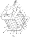
- a heat sink assembly generally designated 10 which includes a circular fan assembly 12 having lead wires 14 extending therefrom and terminating in an electrical connector 16.
- the fan assembly is mounted on top of a heat exchanging section, generally designated 18.
- the heat exchanging section is mounted above a base assembly, generally designated 20.
- heat exchanging section 18 includes a thermally conductive sheet, generally designated 22, which is folded into alternating ridges 24 and troughs 26 defining generally parallel spaced fins 28 having opposite end edges 30 and 32.
- Folded sheet 22 is formed into a generally cylindrical configuration as best seen in Figure 2, whereby troughs 26 form an inner segmented cylinder 34 and ridges 24 form an outer segmented cylinder 36 generally concentric with inner cylinder 34.
- the inner and outer cylinders are "segmented” because they are not defined by continuously smooth surfaces, therefore allowing air to circulate to or from the side of fins 28.
- ridges 24 and troughs 26 form axially extending circumferentially spaced segments of the cylinders.
- the ridges 24 may also include apertures 29 to allow air contained inside the fins 28 to escape in those instances where the end edge 30 of the fins 28 are in direct contact with the heat producing electronic device 38, or in those instances where additional air escape paths are desired to meet the required cooling requirements of the system.
- Heat sink assembly 10 also includes a cylindrical heat conductive rod 40 disposed within inner segmented cylinder 34 defined by troughs 26 of heat exchanging section 22. It can be seen in Figure 2 that the rod has a greater diameter than inner segmented cylinder 34. When the rod is inserted into the cylinder within the inside of heat exchanging section 22, the folded sheet of the section expands in an accordion-like fashion, whereby troughs 34 are biased into engagement with the outer cylindrical surface of rod 40. In other words, the folded sheet which forms heat exchanging section 22 sort of grips the rod to provide good heat conductivity therebetween.
- the rod may be a solid structure, a hollow structure or may comprise a fluid filled heat pipe.
- the diameter of the rod 40 may be the same as the diameter of the inner segmented cylinder 34, with the inner segmented cylinder 34 being affixed to the rod with any known means of affixing two items together, such as an epoxy material or a clamping device (not shown).
- the rod 40 is in direct contact with the heat generating electronic device 38.
- a spring bracket may be used to mount the heat sink assembly 10 to the electronic device to be cooled.
- the spring bracket 42 includes a center ring portion 44 and a pair of diametrically disposed arms 46 terminating in apertured latch hooks 48. Ring portion 44 snaps into a circular peripheral groove 50 about the rod spaced from the bottom of rod 40. Apertured latch hooks 48 at the distal ends of arms 40 snap over a pair of hooked latch bosses 52 on opposite sides of base assembly 20.
- Spring bracket 42 is effective to bias a bottom end 40a of rod 40 into thermal engagement with heat generating electronic device 38.
- the spring bracket also is effective to space end edges 30 at the bottom end of folded sheet 22 above the base plate so that fan assembly 12 circulates cooling air completely through fins 28.
- a fan mounting bracket generally designated 54 (Fig. 2), also includes a ring portion 56 which is appropriately fixed to the top end of rod 40.
- Four arms 58 radiate outwardly from ring portion 56 and terminate in four mounting posts 60.
- Appropriate fasteners (not shown) are inserted through four holes 62 in fan assembly 12 and into mounting posts 60 to hold the fan assembly onto bracket 54 which, in turn, is mounted to the top of rod 40.
- Fan assembly 12 causes cooler air from the atmosphere to flow between and around the fins in a heat exchanging fashion.
- Heat sink assembly 10 may also include a thermally conductive base plate (not shown) which transfers heat to be dissipated to the rod, with the thermally conductive base plate being mounted at the bottom end 40a of rod 40, and end edges 30 of fins 28 at the bottom end of heat exchanging section 22 are located above the base plate.
- the bottom end 40a of rod 40 may be directly attached to the thermally conductive base plate, such as by welding, brazing or epoxy, or the rod 40 and base plate may comprise a single integral structure.
Landscapes
- Cooling Or The Like Of Semiconductors Or Solid State Devices (AREA)
- Cooling Or The Like Of Electrical Apparatus (AREA)
Abstract
Description
Claims (29)
- A heat sink assembly, comprising:a heat exchanging section including a thermally conductive sheet folded into alternating ridges and troughs defining spaced fins having opposite end edges, said folded sheet being formed into a generally cylindrical configuration whereby the troughs form an inner segmented cylinder and the ridges form an outer segmented cylinder generally concentric with the inner cylinder; anda heat conductive rod within said inner segmented cylinder defined by said troughs.
- The heat sink assembly of claim 1 wherein said rod is hollow.
- The heat sink assembly of claim 1 wherein said rod is solid.
- The heat sink assembly of claim 1 wherein said rod comprises a fluid filled heat pipe.
- The heat sink assembly of claim 1 wherein said fins are generally parallel to each other.
- The heat sink assembly of claim 1 wherein said fins are generally parallel to said rod.
- The heat sink assembly of claim 1, including a fan mounted on the heat exchanging section at an end thereof.
- The heat sink assembly of claim 1 wherein at least one of the troughs contains an aperture therein.
- The heat sink assembly of claim 8 wherein the aperture is proximate a bottom end of the trough.
- A heat sink assembly, comprising:a heat exchanging section including a thermally conductive sheet folded into alternating ridges and troughs defining spaced fins having first and second end edges, said folded sheet being formed into a generally cylindrical configuration whereby the troughs form an inner segmented cylinder and the ridges form an outer segmented cylinder generally concentric with the inner cylinder;a thermally conductive base plate above which the heat exchanging section is mounted, with the first end edges of the fins of the cylindrically configured folded sheet being between the base plate and the second end edges of the fins; anda cylindrical heat conductive rod within said inner segmented cylinder defined by said troughs.
- The heat sink assembly of claim 10 wherein said rod is hollow.
- The heat sink assembly of claim 10 wherein said rod is solid.
- The heat sink assembly of claim 10 wherein said rod comprises a fluid filled heat pipe.
- The heat sink assembly of claim 10 wherein one end of said rod is in engagement with the thermally conductive base plate.
- The heat sink assembly of claim 10 wherein said fins are generally parallel to each other.
- The heat sink assembly of claim 10 wherein said fins are generally parallel to said rod.
- The heat sink assembly of claim 14 wherein the rod and the thermally conductive base plate constitute a single, integral structure.
- The heat sink assembly of claim 10 wherein at least one of the troughs contains an aperture therein.
- The heat sink assembly of claim 18 wherein the aperture is proximate the first end edge of the fin.
- A heat sink assembly, comprising:a heat exchanging section including a thermally conductive sheet folded into alternating ridges and troughs defining spaced fins having first and second end edges, said folded sheet being formed into a generally cylindrical configuration whereby the troughs form an inner segmented cylinder and the ridges form an outer segmented cylinder generally concentric with the inner cylinder;a thermally conductive base plate above which the heat exchanging section is mounted, with the first end edges of the fins of the cylindrically configured folded sheet being between the base plate and the second end edges of the fins;a cylindrical heat conductive rod within said inner segmented cylinder defined by said troughs; anda fan mounted on the heat exchanging section at an end thereof opposite the thermally conductive base plate.
- The heat sink assembly of claim 20 wherein said rod is hollow.
- The heat sink assembly of claim 20 wherein said rod is solid.
- The heat sink assembly of claim 20 wherein said rod comprises a fluid filled heat pipe.
- The heat sink assembly of claim 20 wherein one end of said rod is in engagement with the thermally conductive base plate.
- The heat sink assembly of claim 20 wherein said fins are generally parallel to each other.
- The heat sink assembly of claim 20 wherein said fins are generally parallel to said rod.
- The heat sink assembly of claim 24 wherein the rod and the thermally conductive base plate constitute a single, integral structure.
- The heat sink assembly of claim 20 wherein at least one of the troughs contains an aperture therein.
- The heat sink assembly of claim 28 wherein the aperture is proximate the first end edge of the fin.
Applications Claiming Priority (2)
| Application Number | Priority Date | Filing Date | Title |
|---|---|---|---|
| US09/386,103 US6851467B1 (en) | 1999-08-30 | 1999-08-30 | Heat sink assembly |
| US386103 | 1999-08-30 |
Publications (2)
| Publication Number | Publication Date |
|---|---|
| EP1081760A2 true EP1081760A2 (en) | 2001-03-07 |
| EP1081760A3 EP1081760A3 (en) | 2003-04-02 |
Family
ID=23524168
Family Applications (1)
| Application Number | Title | Priority Date | Filing Date |
|---|---|---|---|
| EP00118477A Withdrawn EP1081760A3 (en) | 1999-08-30 | 2000-08-25 | Heat sink assembly |
Country Status (6)
| Country | Link |
|---|---|
| US (2) | US6851467B1 (en) |
| EP (1) | EP1081760A3 (en) |
| JP (2) | JP2001102509A (en) |
| CN (1) | CN1299553C (en) |
| MX (1) | MXPA00008166A (en) |
| TW (1) | TW498993U (en) |
Cited By (17)
| Publication number | Priority date | Publication date | Assignee | Title |
|---|---|---|---|---|
| WO2002041395A3 (en) * | 2000-11-20 | 2002-08-22 | Intel Corp | A high-performance fin configuration for air-cooled heat dissipation device |
| WO2002041396A3 (en) * | 2000-11-20 | 2002-08-29 | Intel Corp | High performance heat sink configurations for use in high density packaging applications |
| US6479895B1 (en) | 2001-05-18 | 2002-11-12 | Intel Corporation | High performance air cooled heat sinks used in high density packaging applications |
| US6501655B1 (en) | 2000-11-20 | 2002-12-31 | Intel Corporation | High performance fin configuration for air cooled heat sinks |
| EP1117284A3 (en) * | 2000-01-11 | 2003-03-19 | Molex Incorporated | Heat sink retainer and heat sink assembly using same |
| US6615910B1 (en) * | 2002-02-20 | 2003-09-09 | Delphi Technologies, Inc. | Advanced air cooled heat sink |
| WO2002099881A3 (en) * | 2001-06-05 | 2004-02-12 | Heat Technology Inc | Heatsink assembly and method of manufacturing the same |
| US6705144B2 (en) | 2001-09-10 | 2004-03-16 | Intel Corporation | Manufacturing process for a radial fin heat sink |
| US6712128B1 (en) | 2002-11-20 | 2004-03-30 | Thermal Corp. | Cylindrical fin tower heat sink and heat exchanger |
| US6830097B2 (en) | 2002-09-27 | 2004-12-14 | Modine Manufacturing Company | Combination tower and serpentine fin heat sink device |
| WO2005059465A1 (en) * | 2003-12-11 | 2005-06-30 | Molex Incorporated | Heat conduction device |
| WO2005109497A1 (en) * | 2004-04-30 | 2005-11-17 | Hewlett-Packard Development Company L.P. | Twin fin arrayed cooling devices |
| EP1353376A3 (en) * | 2002-04-09 | 2006-03-29 | Delphi Technologies, Inc. | Heat sink with multiple surface enhancements |
| WO2006047331A1 (en) * | 2004-10-21 | 2006-05-04 | Hewlett-Packard Development Company, L.P. | Twin fin arrayed cooling device with heat spreader |
| US7120020B2 (en) | 2001-09-10 | 2006-10-10 | Intel Corporation | Electronic assemblies with high capacity bent fin heat sinks |
| EP2053666A1 (en) * | 2007-10-23 | 2009-04-29 | iGUZZINI ILLUMINAZIONE S.p.A. | Heat dissipation device for LEDs and related production method |
| WO2020224777A1 (en) * | 2019-05-08 | 2020-11-12 | Siemens Aktiengesellschaft | Heat sink |
Families Citing this family (46)
| Publication number | Priority date | Publication date | Assignee | Title |
|---|---|---|---|---|
| US5940073A (en) | 1996-05-03 | 1999-08-17 | Starsight Telecast Inc. | Method and system for displaying other information in a TV program guide |
| US6851467B1 (en) * | 1999-08-30 | 2005-02-08 | Molex Incorporated | Heat sink assembly |
| US7225859B2 (en) * | 2000-09-01 | 2007-06-05 | Sharp Kabushiki Kaisha | Heat exchanger element and heat exchanger member for a stirling cycle refrigerator and method of manufacturing such a heat exchanger member |
| US6543522B1 (en) * | 2001-10-31 | 2003-04-08 | Hewlett-Packard Development Company, L.P. | Arrayed fin cooler |
| CN1307716C (en) * | 2002-12-06 | 2007-03-28 | 诺亚公司 | Multidirectional liquid storage slot heat conducting apparatus and method |
| CN1293627C (en) * | 2003-01-15 | 2007-01-03 | 诺亚公司 | Energy transfer method and device with unidirectional airflow and hollow cavity |
| TWM246687U (en) | 2003-10-28 | 2004-10-11 | Hon Hai Prec Ind Co Ltd | Heat dissipation device |
| US7055577B2 (en) * | 2004-02-12 | 2006-06-06 | Hon Hai Precision Ind. Co., Ltd. | Heat dissipation device for electronic device |
| US7149083B2 (en) * | 2004-03-05 | 2006-12-12 | Hul-Chun Hsu | Heat dissipation structure |
| CN2706868Y (en) * | 2004-05-26 | 2005-06-29 | 鸿富锦精密工业(深圳)有限公司 | Radiating device combination |
| CN2777753Y (en) * | 2005-01-19 | 2006-05-03 | 富准精密工业(深圳)有限公司 | Radiator |
| TWI274539B (en) * | 2005-04-01 | 2007-02-21 | Delta Electronics Inc | Heat dissipating assembly with composite heat dissipating structure |
| EP1946030A1 (en) * | 2005-11-09 | 2008-07-23 | TIR Technology LP | Passive thermal management system |
| JP2007273868A (en) * | 2006-03-31 | 2007-10-18 | Fujikura Ltd | heatsink |
| US7362573B2 (en) * | 2006-04-28 | 2008-04-22 | Fu Zhun Precision Industry (Shen Zhen) Co., Ltd. | Heat dissipation device |
| US8832742B2 (en) | 2006-10-06 | 2014-09-09 | United Video Properties, Inc. | Systems and methods for acquiring, categorizing and delivering media in interactive media guidance applications |
| CN101203117B (en) * | 2006-12-13 | 2010-08-25 | 富准精密工业(深圳)有限公司 | heat sink |
| TW200942145A (en) * | 2008-03-20 | 2009-10-01 | Jun-Guang Luo | Heat-dissipating device with multiple heat sources |
| USD593963S1 (en) * | 2008-04-23 | 2009-06-09 | 4187318 Canada Inc. | Modular heat sink |
| TWM348981U (en) * | 2008-06-12 | 2009-01-11 | Acpa Energy Conversion Devices Co Ltd | Heat dissipation module |
| USD592613S1 (en) * | 2008-06-18 | 2009-05-19 | 4187318 Canada Inc. | Heat sink |
| US9228732B2 (en) | 2008-07-08 | 2016-01-05 | Us Vaopto, Inc. | Modular LED lighting systems, including flexible, rigid, and waterproof lighting strips and connectors |
| US7972040B2 (en) | 2008-08-22 | 2011-07-05 | Virginia Optoelectronics, Inc. | LED lamp assembly |
| USD603810S1 (en) * | 2008-08-29 | 2009-11-10 | Lighthouse Technology Co., Ltd. | Heat sink for illuminating device |
| US7740380B2 (en) * | 2008-10-29 | 2010-06-22 | Thrailkill John E | Solid state lighting apparatus utilizing axial thermal dissipation |
| US7972037B2 (en) | 2008-11-26 | 2011-07-05 | Deloren E. Anderson | High intensity replaceable light emitting diode module and array |
| JP2010219428A (en) * | 2009-03-18 | 2010-09-30 | Delong Chen | Structure of led heat radiator |
| US20110030920A1 (en) * | 2009-08-04 | 2011-02-10 | Asia Vital Components (Shen Zhen) Co., Ltd. | Heat Sink Structure |
| USD642732S1 (en) | 2010-03-23 | 2011-08-02 | Cooper Technologies Company | Lighting fixture |
| US10103089B2 (en) * | 2010-03-26 | 2018-10-16 | Hamilton Sundstrand Corporation | Heat transfer device with fins defining air flow channels |
| DE112010005450B4 (en) | 2010-04-05 | 2018-06-14 | Cooper Technologies Company (N.D.Ges.D. Staates Delaware) | Lighting arrangements with a controlled, directed heat transfer |
| US8757852B2 (en) | 2010-10-27 | 2014-06-24 | Cree, Inc. | Lighting apparatus |
| US20120186798A1 (en) * | 2011-01-26 | 2012-07-26 | Celsia Technologies Taiwan, I | Cooling module for led lamp |
| USD662898S1 (en) * | 2011-03-24 | 2012-07-03 | Graftech International Holdings Inc. | Heat sink for LED light bulb |
| USD683890S1 (en) * | 2011-04-11 | 2013-06-04 | Cree, Inc. | Lighting fixture |
| CN102271486A (en) * | 2011-07-21 | 2011-12-07 | 尹钟哲 | Radiating structure, and application, manufacturing device and manufacturing method thereof |
| TWI512440B (en) * | 2012-08-01 | 2015-12-11 | Asia Vital Components Co Ltd | Heat-dissipating device and method for manufacturing the same |
| DE102012217399A1 (en) * | 2012-09-26 | 2014-03-27 | Robert Bosch Gmbh | Cooling structure for cooling a cylinder |
| US9326424B2 (en) * | 2014-09-10 | 2016-04-26 | Opentv, Inc. | Heat sink assembly and method of utilizing a heat sink assembly |
| US9581322B2 (en) | 2014-09-30 | 2017-02-28 | Aeonovalite Technologies, Inc. | Heat-sink for high bay LED device, high bay LED device and methods of use thereof |
| CN106143521B (en) * | 2016-07-20 | 2018-10-02 | 广州市日森机械股份有限公司 | A kind of intelligent high-pressure hot-air cooling operations unit |
| JP7023141B2 (en) | 2018-03-06 | 2022-02-21 | 一般財団法人沖縄美ら島財団 | Deep-sea creature capture device and capture method |
| US11204340B2 (en) | 2018-09-21 | 2021-12-21 | Rosemount Inc. | Forced convection heater |
| US11041660B2 (en) * | 2018-09-21 | 2021-06-22 | Rosemount Inc. | Forced convection heater |
| TWD210771S (en) * | 2020-04-09 | 2021-04-01 | 宏碁股份有限公司 | Heat-dissipation fin |
| WO2022105306A1 (en) * | 2020-11-18 | 2022-05-27 | 纽福克斯光电科技(上海)有限公司 | Novel cooling apparatus |
Family Cites Families (36)
| Publication number | Priority date | Publication date | Assignee | Title |
|---|---|---|---|---|
| DE44339C (en) * | J. BRUUN in Kopenhagen | Innovation on the lubrication pump protected by patent no. 43296 with a fixed spiral ring and rotating flat slide control | ||
| US2161417A (en) * | 1936-11-16 | 1939-06-06 | Frederick T Holmes | Water heater |
| US2396216A (en) * | 1943-04-03 | 1946-03-05 | Stevenson Jordan & Harrison In | Method for making air-cooled cylinders |
| US2413179A (en) * | 1943-09-20 | 1946-12-24 | Westinghouse Electric Corp | Radiator |
| USRE25184E (en) | 1959-08-03 | 1962-06-12 | Mcadam | |
| NL260951A (en) * | 1960-03-07 | |||
| US3185756A (en) * | 1960-05-02 | 1965-05-25 | Cool Fin Electronics Corp | Heat-dissipating tube shield |
| US3152217A (en) * | 1960-12-01 | 1964-10-06 | Rca Corp | Heat dissipating shield for electronic components |
| US3187082A (en) * | 1961-02-01 | 1965-06-01 | Cool Fin Electronics Corp | Heat dissipating electrical shield |
| US3239003A (en) | 1962-11-30 | 1966-03-08 | Wakefield Engineering Co Inc | Heat transfer |
| FR1462160A (en) | 1963-05-28 | 1966-04-15 | Chausson Usines Sa | Method of manufacturing a heat exchanger element, element obtained by this process and application of this element to the constitution of particular heat exchangers |
| US3372733A (en) * | 1964-02-11 | 1968-03-12 | Russell J. Callender | Method of maintaining electrical characteristics of electron tubes and transistors an structure therefor |
| US3280907A (en) | 1964-09-01 | 1966-10-25 | Hoffman Sidney | Energy transfer device |
| US3566958A (en) | 1968-12-18 | 1971-03-02 | Gen Systems Inc | Heat sink for electrical devices |
| JPS5989443A (en) | 1982-11-15 | 1984-05-23 | Nec Corp | Brazing process of heat radiating blade |
| US4607685A (en) * | 1984-07-06 | 1986-08-26 | Burroughs Corporation | Heat sink for integrated circuit package |
| US4715438A (en) | 1986-06-30 | 1987-12-29 | Unisys Corporation | Staggered radial-fin heat sink device for integrated circuit package |
| US4753290A (en) | 1986-07-18 | 1988-06-28 | Unisys Corporation | Reduced-stress heat sink device |
| US4682651A (en) | 1986-09-08 | 1987-07-28 | Burroughs Corporation (Now Unisys Corporation) | Segmented heat sink device |
| US4716494A (en) | 1986-11-07 | 1987-12-29 | Amp Incorporated | Retention system for removable heat sink |
| US4733293A (en) | 1987-02-13 | 1988-03-22 | Unisys Corporation | Heat sink device assembly for encumbered IC package |
| US5019880A (en) | 1988-01-07 | 1991-05-28 | Prime Computer, Inc. | Heat sink apparatus |
| US5704416A (en) | 1993-09-10 | 1998-01-06 | Aavid Laboratories, Inc. | Two phase component cooler |
| US5597034A (en) | 1994-07-01 | 1997-01-28 | Digital Equipment Corporation | High performance fan heatsink assembly |
| US5810554A (en) | 1995-05-31 | 1998-09-22 | Sanyo Denki Co., Ltd. | Electronic component cooling apparatus |
| JP3058818B2 (en) | 1995-10-05 | 2000-07-04 | 山洋電気株式会社 | Heat sink for cooling electronic components |
| CN2249920Y (en) * | 1996-01-29 | 1997-03-19 | 钟豪胜 | CPU cooler |
| US5785116A (en) | 1996-02-01 | 1998-07-28 | Hewlett-Packard Company | Fan assisted heat sink device |
| CN2267518Y (en) * | 1996-03-29 | 1997-11-12 | 陈熙亮 | Transformer cooling device |
| EP0809287A1 (en) | 1996-05-22 | 1997-11-26 | Jean Amigo | Heat dissipation device for an integrated circuit |
| US5794685A (en) | 1996-12-17 | 1998-08-18 | Hewlett-Packard Company | Heat sink device having radial heat and airflow paths |
| CN2297615Y (en) * | 1997-01-22 | 1998-11-18 | 中国石化第四建设公司 | Heating device for oxygen pressure reducer |
| US5828551A (en) | 1997-03-04 | 1998-10-27 | Hoshino Kinzoku Koygo Kabushiki Kaisha | Heat sink apparatus for an electronic component |
| US5927385A (en) | 1998-01-21 | 1999-07-27 | Yeh; Ming Hsin | Cooling device for the CPU of computer |
| US6851467B1 (en) * | 1999-08-30 | 2005-02-08 | Molex Incorporated | Heat sink assembly |
| TW529737U (en) * | 2001-06-20 | 2003-04-21 | Foxconn Prec Components Co Ltd | Heat sink apparatus |
-
1999
- 1999-08-30 US US09/386,103 patent/US6851467B1/en not_active Expired - Fee Related
-
2000
- 2000-08-21 MX MXPA00008166A patent/MXPA00008166A/en unknown
- 2000-08-25 EP EP00118477A patent/EP1081760A3/en not_active Withdrawn
- 2000-08-30 JP JP2000260340A patent/JP2001102509A/en active Pending
- 2000-08-30 CN CNB001263218A patent/CN1299553C/en not_active Expired - Fee Related
- 2000-09-27 TW TW089214921U patent/TW498993U/en unknown
-
2004
- 2004-04-29 US US10/834,693 patent/US20040200601A1/en not_active Abandoned
- 2004-05-17 JP JP2004002727U patent/JP3105270U/en not_active Expired - Lifetime
Cited By (30)
| Publication number | Priority date | Publication date | Assignee | Title |
|---|---|---|---|---|
| EP1117284A3 (en) * | 2000-01-11 | 2003-03-19 | Molex Incorporated | Heat sink retainer and heat sink assembly using same |
| GB2384911A (en) * | 2000-11-20 | 2003-08-06 | Intel Corp | A high-performance fin configuration for air-cooled heat dissipation device |
| US6501655B1 (en) | 2000-11-20 | 2002-12-31 | Intel Corporation | High performance fin configuration for air cooled heat sinks |
| US6535385B2 (en) | 2000-11-20 | 2003-03-18 | Intel Corporation | High performance heat sink configurations for use in high density packaging applications |
| WO2002041396A3 (en) * | 2000-11-20 | 2002-08-29 | Intel Corp | High performance heat sink configurations for use in high density packaging applications |
| US6845010B2 (en) | 2000-11-20 | 2005-01-18 | Intel Corporation | High performance heat sink configurations for use in high density packaging applications |
| DE10196917B4 (en) * | 2000-11-20 | 2009-11-05 | Intel Corporation, Santa Clara | High performance fin construction for an air cooled heat sink |
| US6633484B1 (en) | 2000-11-20 | 2003-10-14 | Intel Corporation | Heat-dissipating devices, systems, and methods with small footprint |
| WO2002041395A3 (en) * | 2000-11-20 | 2002-08-22 | Intel Corp | A high-performance fin configuration for air-cooled heat dissipation device |
| GB2384911B (en) * | 2000-11-20 | 2005-03-16 | Intel Corp | A high-performance fin configuration for air-cooled heat dissipation device |
| US6479895B1 (en) | 2001-05-18 | 2002-11-12 | Intel Corporation | High performance air cooled heat sinks used in high density packaging applications |
| WO2002099881A3 (en) * | 2001-06-05 | 2004-02-12 | Heat Technology Inc | Heatsink assembly and method of manufacturing the same |
| US7284596B2 (en) | 2001-06-05 | 2007-10-23 | Heat Technology, Inc. | Heatsink assembly and method of manufacturing the same |
| US6827130B2 (en) | 2001-06-05 | 2004-12-07 | Heat Technology, Inc. | Heatsink assembly and method of manufacturing the same |
| US7200934B2 (en) | 2001-09-10 | 2007-04-10 | Intel Corporation | Electronic assemblies with high capacity heat sinks and methods of manufacture |
| US7911790B2 (en) | 2001-09-10 | 2011-03-22 | Intel Corporation | Electronic assemblies with high capacity curved and bent fin heat sinks and associated methods |
| US6705144B2 (en) | 2001-09-10 | 2004-03-16 | Intel Corporation | Manufacturing process for a radial fin heat sink |
| US7120020B2 (en) | 2001-09-10 | 2006-10-10 | Intel Corporation | Electronic assemblies with high capacity bent fin heat sinks |
| US6615910B1 (en) * | 2002-02-20 | 2003-09-09 | Delphi Technologies, Inc. | Advanced air cooled heat sink |
| EP1353376A3 (en) * | 2002-04-09 | 2006-03-29 | Delphi Technologies, Inc. | Heat sink with multiple surface enhancements |
| US6830097B2 (en) | 2002-09-27 | 2004-12-14 | Modine Manufacturing Company | Combination tower and serpentine fin heat sink device |
| US6712128B1 (en) | 2002-11-20 | 2004-03-30 | Thermal Corp. | Cylindrical fin tower heat sink and heat exchanger |
| WO2005059465A1 (en) * | 2003-12-11 | 2005-06-30 | Molex Incorporated | Heat conduction device |
| US8042605B2 (en) | 2003-12-11 | 2011-10-25 | Molex Incorporated | Heat conduction device |
| US7497248B2 (en) | 2004-04-30 | 2009-03-03 | Hewlett-Packard Development Company, L.P. | Twin fin arrayed cooling device |
| WO2005109497A1 (en) * | 2004-04-30 | 2005-11-17 | Hewlett-Packard Development Company L.P. | Twin fin arrayed cooling devices |
| WO2006047331A1 (en) * | 2004-10-21 | 2006-05-04 | Hewlett-Packard Development Company, L.P. | Twin fin arrayed cooling device with heat spreader |
| US7296619B2 (en) | 2004-10-21 | 2007-11-20 | Hewlett-Packard Development Company, L.P. | Twin fin arrayed cooling device with heat spreader |
| EP2053666A1 (en) * | 2007-10-23 | 2009-04-29 | iGUZZINI ILLUMINAZIONE S.p.A. | Heat dissipation device for LEDs and related production method |
| WO2020224777A1 (en) * | 2019-05-08 | 2020-11-12 | Siemens Aktiengesellschaft | Heat sink |
Also Published As
| Publication number | Publication date |
|---|---|
| CN1299553C (en) | 2007-02-07 |
| EP1081760A3 (en) | 2003-04-02 |
| MXPA00008166A (en) | 2002-03-15 |
| TW498993U (en) | 2002-08-11 |
| US20040200601A1 (en) | 2004-10-14 |
| JP3105270U (en) | 2004-10-21 |
| JP2001102509A (en) | 2001-04-13 |
| CN1286593A (en) | 2001-03-07 |
| US6851467B1 (en) | 2005-02-08 |
Similar Documents
| Publication | Publication Date | Title |
|---|---|---|
| US6851467B1 (en) | Heat sink assembly | |
| US6557626B1 (en) | Heat sink retainer and Heat sink assembly using same | |
| US6625021B1 (en) | Heat sink with heat pipes and fan | |
| US6538888B1 (en) | Radial base heatsink | |
| US6145586A (en) | Heat sink module with heat dissipating device | |
| US6408935B1 (en) | Heat sink assembly with over-molded cooling fins | |
| JP3851875B2 (en) | Cooling device and electronic equipment | |
| US6446708B1 (en) | Heat dissipating device | |
| EP0889524A2 (en) | Scalable and modular heat sink-heat pipe cooling system | |
| US20030019610A1 (en) | Rapidly self - heat-conductive heat - dissipating module | |
| US20050094377A1 (en) | Heat sink assembly incorporating spring clip | |
| US20040200608A1 (en) | Plate fins with vanes for redirecting airflow | |
| US20040118552A1 (en) | Heat-dissipating device | |
| KR20190011980A (en) | Thermal sync structure by hair-cell | |
| US6532141B1 (en) | Heat-dissipating device for electronic component | |
| US6542370B1 (en) | Heat dissipating device for a CPU | |
| US6816374B2 (en) | High efficiency heat sink/air cooler system for heat-generating components | |
| KR200496760Y1 (en) | Cooling apparatus of electronic equipment | |
| JP3058818B2 (en) | Heat sink for cooling electronic components | |
| JP2004079754A (en) | heatsink | |
| US7447025B2 (en) | Heat dissipation device | |
| US20030189813A1 (en) | High performance heat sink configurations for use in high density packaging applications | |
| JP2003100974A (en) | Air-cooling semiconductor heat sink | |
| US7365978B2 (en) | Heat dissipating device | |
| JP3819316B2 (en) | Tower type heat sink |
Legal Events
| Date | Code | Title | Description |
|---|---|---|---|
| PUAI | Public reference made under article 153(3) epc to a published international application that has entered the european phase |
Free format text: ORIGINAL CODE: 0009012 |
|
| AK | Designated contracting states |
Kind code of ref document: A2 Designated state(s): AT BE CH CY DE DK ES FI FR GB GR IE IT LI LU MC NL PT SE |
|
| AX | Request for extension of the european patent |
Free format text: AL;LT;LV;MK;RO;SI |
|
| PUAL | Search report despatched |
Free format text: ORIGINAL CODE: 0009013 |
|
| AK | Designated contracting states |
Kind code of ref document: A3 Designated state(s): AT BE CH CY DE DK ES FI FR GB GR IE IT LI LU MC NL PT SE Designated state(s): AT BE CH CY DE DK ES FI FR GB GR IE IT LI LU MC NL PT SE |
|
| AX | Request for extension of the european patent |
Extension state: AL LT LV MK RO SI |
|
| AKX | Designation fees paid |
Designated state(s): DE FR GB IE IT |
|
| STAA | Information on the status of an ep patent application or granted ep patent |
Free format text: STATUS: THE APPLICATION IS DEEMED TO BE WITHDRAWN |
|
| 18D | Application deemed to be withdrawn |
Effective date: 20031003 |