EP1081745A2 - Method of detaching article and apparatus - Google Patents
Method of detaching article and apparatus Download PDFInfo
- Publication number
- EP1081745A2 EP1081745A2 EP00307685A EP00307685A EP1081745A2 EP 1081745 A2 EP1081745 A2 EP 1081745A2 EP 00307685 A EP00307685 A EP 00307685A EP 00307685 A EP00307685 A EP 00307685A EP 1081745 A2 EP1081745 A2 EP 1081745A2
- Authority
- EP
- European Patent Office
- Prior art keywords
- article
- sensitive adhesive
- pressure sensitive
- laminate unit
- coated sheet
- Prior art date
- Legal status (The legal status is an assumption and is not a legal conclusion. Google has not performed a legal analysis and makes no representation as to the accuracy of the status listed.)
- Granted
Links
Images


Classifications
-
- H—ELECTRICITY
- H10—SEMICONDUCTOR DEVICES; ELECTRIC SOLID-STATE DEVICES NOT OTHERWISE PROVIDED FOR
- H10P—GENERIC PROCESSES OR APPARATUS FOR THE MANUFACTURE OR TREATMENT OF DEVICES COVERED BY CLASS H10
- H10P54/00—Cutting or separating of wafers, substrates or parts of devices
-
- H—ELECTRICITY
- H10—SEMICONDUCTOR DEVICES; ELECTRIC SOLID-STATE DEVICES NOT OTHERWISE PROVIDED FOR
- H10P—GENERIC PROCESSES OR APPARATUS FOR THE MANUFACTURE OR TREATMENT OF DEVICES COVERED BY CLASS H10
- H10P72/00—Handling or holding of wafers, substrates or devices during manufacture or treatment thereof
- H10P72/04—Apparatus for manufacture or treatment
- H10P72/0428—Apparatus for mechanical treatment or grinding or cutting
-
- H—ELECTRICITY
- H10—SEMICONDUCTOR DEVICES; ELECTRIC SOLID-STATE DEVICES NOT OTHERWISE PROVIDED FOR
- H10P—GENERIC PROCESSES OR APPARATUS FOR THE MANUFACTURE OR TREATMENT OF DEVICES COVERED BY CLASS H10
- H10P72/00—Handling or holding of wafers, substrates or devices during manufacture or treatment thereof
- H10P72/70—Handling or holding of wafers, substrates or devices during manufacture or treatment thereof for supporting or gripping
- H10P72/74—Handling or holding of wafers, substrates or devices during manufacture or treatment thereof for supporting or gripping using temporarily an auxiliary support
- H10P72/7402—Wafer tapes, e.g. grinding or dicing support tapes
-
- H—ELECTRICITY
- H10—SEMICONDUCTOR DEVICES; ELECTRIC SOLID-STATE DEVICES NOT OTHERWISE PROVIDED FOR
- H10P—GENERIC PROCESSES OR APPARATUS FOR THE MANUFACTURE OR TREATMENT OF DEVICES COVERED BY CLASS H10
- H10P72/00—Handling or holding of wafers, substrates or devices during manufacture or treatment thereof
- H10P72/70—Handling or holding of wafers, substrates or devices during manufacture or treatment thereof for supporting or gripping
- H10P72/74—Handling or holding of wafers, substrates or devices during manufacture or treatment thereof for supporting or gripping using temporarily an auxiliary support
- H10P72/744—Details of chemical or physical process used for separating the auxiliary support from a device or a wafer
-
- H—ELECTRICITY
- H10—SEMICONDUCTOR DEVICES; ELECTRIC SOLID-STATE DEVICES NOT OTHERWISE PROVIDED FOR
- H10P—GENERIC PROCESSES OR APPARATUS FOR THE MANUFACTURE OR TREATMENT OF DEVICES COVERED BY CLASS H10
- H10P72/00—Handling or holding of wafers, substrates or devices during manufacture or treatment thereof
- H10P72/70—Handling or holding of wafers, substrates or devices during manufacture or treatment thereof for supporting or gripping
- H10P72/74—Handling or holding of wafers, substrates or devices during manufacture or treatment thereof for supporting or gripping using temporarily an auxiliary support
- H10P72/744—Details of chemical or physical process used for separating the auxiliary support from a device or a wafer
- H10P72/7442—Separation by peeling
-
- Y—GENERAL TAGGING OF NEW TECHNOLOGICAL DEVELOPMENTS; GENERAL TAGGING OF CROSS-SECTIONAL TECHNOLOGIES SPANNING OVER SEVERAL SECTIONS OF THE IPC; TECHNICAL SUBJECTS COVERED BY FORMER USPC CROSS-REFERENCE ART COLLECTIONS [XRACs] AND DIGESTS
- Y10—TECHNICAL SUBJECTS COVERED BY FORMER USPC
- Y10S—TECHNICAL SUBJECTS COVERED BY FORMER USPC CROSS-REFERENCE ART COLLECTIONS [XRACs] AND DIGESTS
- Y10S438/00—Semiconductor device manufacturing: process
- Y10S438/976—Temporary protective layer
-
- Y—GENERAL TAGGING OF NEW TECHNOLOGICAL DEVELOPMENTS; GENERAL TAGGING OF CROSS-SECTIONAL TECHNOLOGIES SPANNING OVER SEVERAL SECTIONS OF THE IPC; TECHNICAL SUBJECTS COVERED BY FORMER USPC CROSS-REFERENCE ART COLLECTIONS [XRACs] AND DIGESTS
- Y10—TECHNICAL SUBJECTS COVERED BY FORMER USPC
- Y10T—TECHNICAL SUBJECTS COVERED BY FORMER US CLASSIFICATION
- Y10T156/00—Adhesive bonding and miscellaneous chemical manufacture
- Y10T156/11—Methods of delaminating, per se; i.e., separating at bonding face
- Y10T156/1153—Temperature change for delamination [e.g., heating during delaminating, etc.]
-
- Y—GENERAL TAGGING OF NEW TECHNOLOGICAL DEVELOPMENTS; GENERAL TAGGING OF CROSS-SECTIONAL TECHNOLOGIES SPANNING OVER SEVERAL SECTIONS OF THE IPC; TECHNICAL SUBJECTS COVERED BY FORMER USPC CROSS-REFERENCE ART COLLECTIONS [XRACs] AND DIGESTS
- Y10—TECHNICAL SUBJECTS COVERED BY FORMER USPC
- Y10T—TECHNICAL SUBJECTS COVERED BY FORMER US CLASSIFICATION
- Y10T29/00—Metal working
- Y10T29/49—Method of mechanical manufacture
- Y10T29/49815—Disassembling
- Y10T29/49819—Disassembling with conveying of work or disassembled work part
-
- Y—GENERAL TAGGING OF NEW TECHNOLOGICAL DEVELOPMENTS; GENERAL TAGGING OF CROSS-SECTIONAL TECHNOLOGIES SPANNING OVER SEVERAL SECTIONS OF THE IPC; TECHNICAL SUBJECTS COVERED BY FORMER USPC CROSS-REFERENCE ART COLLECTIONS [XRACs] AND DIGESTS
- Y10—TECHNICAL SUBJECTS COVERED BY FORMER USPC
- Y10T—TECHNICAL SUBJECTS COVERED BY FORMER US CLASSIFICATION
- Y10T29/00—Metal working
- Y10T29/49—Method of mechanical manufacture
- Y10T29/49815—Disassembling
- Y10T29/49822—Disassembling by applying force
Definitions
- the present invention relates to a method of detaching an article fixed through a pressure sensitive adhesive double coated sheet and a detacher apparatus therefor.
- the wafer of a semiconductor such as silicon is produced in the form of a disc of large diameter.
- a circuit pattern is formed on a surface of the semiconductor wafer, and the back thereof is ground.
- a pressure sensitive adhesive sheet which is produced by coating a soft base with a pressure sensitive adhesive, is used for fixing the semiconductor wafer to, for example, a table while protecting the surface of the semiconductor wafer provided with a circuit pattern.
- the semiconductor wafer may be cracked during the detaching operation by residual stress resulting from accumulation of the tension applied at the time of sticking.
- the inventors proposed a new pressure sensitive adhesive double coated sheet having pressure sensitive adhesive layers superimposed on a heat shrinkable base, which enabled easily detaching articles by first exposing it to ultraviolet light and thereafter heating the same.
- the first exposure to ultraviolet light lowered the adhesive strength of the pressure sensitive adhesive layers, and the subsequent heating induced shrinking and deformation of the heat shrinkable base to thereby enable easily detaching the articles from the pressure sensitive adhesive sheet.
- this heat shrink pressure sensitive adhesive sheet has caused the following problem. That is, in the use of the heat shrink pressure sensitive adhesive sheet, shrinking begins at the part which is heated to raise its temperature. When the article is one of small area, the whole is heated and detached within a short period of time, irrespective of the location of heating. Thus, with respect to articles of small area, cracking of such articles has been rare. However, when an article of large area is heated at its center, detaching begins at a part near a heating source with the result that a substantial tensile force is exerted between there and an outer part not yet satisfactorily heated. The tensile force is likely to cause cracking of articles.
- the present invention aims to provide a method of detaching an article fixed through a pressure sensitive adhesive double coated sheet and a detacher apparatus therefor, which enables efficiently detaching articles, such as extremely thin wafers, without cracking thereof by the use of a heat shrink pressure sensitive adhesive double coated sheet.
- a method of detaching an article from a laminate unit, the laminate unit comprising a support plate and, fixed thereto, the article, the fixing effected through a pressure sensitive adhesive double coated sheet deformable by heating to thereby exert a peeling effect which method comprises:
- At least one outer part of the laminate unit is initially heated up and thereafter the heated up part can be slowly extended to other regions.
- the article can be easily detached from the initially heated up part of the pressure sensitive adhesive double coated sheet.
- the initially heated up outer region of the laminate unit is a peripheral region extending in approximately a doughnut shape from a center of the laminate unit.
- the peripheral region is detached initially and the inner region can be detached later.
- the article even if extremely thin, can be easily detached, without cracking thereof, from the pressure sensitive adhesive double coated sheet.
- a detacher apparatus for detaching an article from a laminate unit, the laminate unit comprising a support plate and, fixed thereto, the article, the fixing effected through a pressure sensitive adhesive double coated sheet deformable by heating to thereby exert a peeling effect
- the apparatus comprises heat-up means, the heat-up means including a first heat-up member capable of heating up at least one outer part of the laminate unit and a second heat-up member capable of heating up other parts of the laminate unit later than the first heat-up member.
- This apparatus enables easily detaching the article, even if extremely thin, from the pressure sensitive adhesive double coated sheet without cracking of the article.
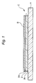
- Fig. 1 shows laminate unit C for use in this embodiment.
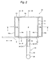
- Fig. 2 is a schematic plan view of a detacher apparatus capable of heating the laminate unit C and effecting detaching.
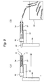
- Fig. 3 is a section on the line I-I of Fig. 2.
- the laminate unit C comprises pressure sensitive adhesive double coated sheet 1, support plate A stuck to one side of the pressure sensitive adhesive double coated sheet 1 and article B stuck to the opposite side of the pressure sensitive adhesive double coated sheet 1.
- the article B is an unchipped semiconductor wafer.
- the article B is not limited thereto and may be any of insulating bases made of a ceramic or resin, various electronic elements, optical elements such as glass or quartz plates and composites thereof as long as these are planar and have relatively large areas.
- the shape thereof is not limited to the disc form and can be, for example, a rectangular form.
- the pressure sensitive adhesive double coated sheet 1 for use in this embodiment comprises heat shrinkable base 3 and, superimposed on both sides thereof, pressure sensitive adhesive layers 2a, 2b.
- any of the known pressure sensitive adhesives can be used for forming the pressure sensitive adhesive layers 2a, 2b, it is preferred that at least one of the pressure sensitive adhesive layers 2a, 2b be composed of an ultraviolet curable pressure sensitive adhesive.
- both of the pressure sensitive adhesive layers 2a, 2b are composed of an ultraviolet curable pressure sensitive adhesive.
- the pressure sensitive adhesive double coated sheet 1 is not limited to that of this embodiment, and may be, for example, a pressure sensitive adhesive double coated sheet in which a heat foaming agent is mixed in the pressure sensitive adhesive and causes foaming upon being heated to thereby deform the pressure sensitive adhesive layers.
- the support plate A is generally a rigid flat plate.
- the pressure sensitive adhesive layer 2a, or 2b is composed of an ultraviolet curable pressure sensitive adhesive
- the support plate A be, for example, a rigid glass plate or plastic plate composed of an ultraviolet permeable material. It is preferred that the pressure sensitive adhesive double coated sheet 1, support plate A and article B all have approximately the same configuration.
- the detacher apparatus of this embodiment is one capable of heating the above laminate unit C so that the pressure sensitive adhesive double coated sheet 1 interposed between the support plate A and the article B can naturally be detached.
- the detacher apparatus 20 at its inside, has high-temperature chamber 4 enclosed by a double wall.
- air channels 11a, 11b are provided between a pair of inner side walls 8a, 8b opposite to each other and a pair of outer side walls 10a, 10b opposite to the inner side walls 8a, 8b.
- These inner side walls 8a, 8b as shown in Figs. 2 and 3, are provided with slits 13, 14 arranged at given intervals in the vertical direction.
- the air inside the high-temperature chamber 4 can flow from one inner side wall to the other inner side wall.
- fan 12 provided at a ceiling portion is driven, as shown in Fig. 3
- air is led so as to flow from the left air channel 11a through the slits 13 into the high-temperature chamber 4.
- the air having flowed into the high-temperature chamber 4 is led through the slits 14 into the right air channel 11b, and further led upwards.
- air circulation as shown by arrows in Fig. 3 is effected.
- the high-temperature chamber 4 includes box-shaped chamber frame 5 with its one side open.
- This chamber frame 5 is partitioned by the left and right side walls 8a, 8b and the upper and lower side walls 8c, 8d and includes lid 6 that covers opening 5a of the chamber frame 5.
- This lid 6 is slidable as shown in Fig. 2.
- This lid 6 is not limited to opening movement in the horizontal direction as shown in Fig. 2, and, for example, may undergo opening movement in the vertical direction.
- the box-shaped chamber frame 5 is provided with shelf plates 7 protruding from rear side wall 8e, arranged at given intervals in the vertical direction.
- Each of these shelf plates 7 at an upper surface thereof is provided with minute through holes connected to a vacuum pump and a valve, both not shown, and so constructed that a planar article of, for example, disc or rectangular form can be attracted and fixed thereto by a negative pressure.
- the left and right side walls 8a, 8b and the upper and lower side walls 8c, 8d of the chamber frame 5 are provided with heat-up means 15.
- These heat-up means 15 are for the purpose of heating the inside of the high-temperature chamber 4.
- known heat-up means such as a sheathed wire heater, a rubber heater and a far infrared heater can be used.
- the heat-up means is not particularly limited.
- the rear side wall 8e as a constituent of the high-temperature chamber 4 is provided with apertures 9 arranged at given intervals in the vertical direction.
- vertically movable presser plates 17 are housed in the high-temperature chamber 4, namely the chamber frame 5.
- the vertical movements of these presser plates 17 may be either separately controlled or simultaneously controlled.
- Spring 22 is provided between each of the presser plates 17 and the shelf plate 7 positioned above the presser plate 17. With respect to the uppermost presser plate 17, the spring 22 is provided between the presser plate 17 and the upper side wall 8c.
- the apparatus is so constructed that, when these presser plates 17 are positioned downwards, the springs 22 are elongated to thereby exert an upward tensile force.
- Each of the springs 22 is adjusted so that, in the elongated state, the upward tensile force substantially balances with the gravity of the presser plate 17.
- the apparatus is so constructed that, when the pressure sensitive adhesive double coated sheet 1 is deformed, there is no downward exertion of the gravity of the presser plate 17 to thereby be free from hindering the deformation of the pressure sensitive adhesive double coated sheet 1.
- Each of the presser plates 17 at a lower surface thereof, like the above shelf plates 7, is provided with minute through holes connected to a vacuum pump and a valve, both not shown, and thus provided with such suction means that a planar article can be attracted and fixed thereto by a negative pressure. Therefore, the apparatus is so constructed that the laminate unit C disposed between the presser plate 17 and the shelf plate 7 can be attracted and fixed by a negative pressure from not only the downward position but also the upward position.
- the heat-up means provided on the presser plates 17 and the shelf plates 7 will be described below.
- the heat-up means 35 provided on the presser plates 17 and the shelf plates 7 have exactly the same construction, so that description will be made with reference only to the heat-up means 35 provided on the shelf plates 7.
- these heat-up means 35 include two heat-up parts, i.e., outer heater 31 for heating an outer region and inner heater 19 for heating an inner region.
- the outer heater 31 includes four heater parts 31a, 31b, 31c, 31d arranged so as to form a ring.
- the inner heater 19 is provided in approximately ringlike form inside the outer heater 31. With respect to the inner heater 19, it is provided with not only the ringlike part but also linear heater part 18 arranged so as to cross the center of the ringlike part.
- takeout means for performing taking in and out of the laminate unit C, arranged in front of the high-temperature chamber 4 of the detacher apparatus 20, will be described with reference to Figs. 2 and 7.
- the takeout means 30 is installed in the vicinity of the lid 6 as a constituent of the high-temperature chamber 4.
- the takeout means 30 includes rotatable pillar 38 and vertically movable horizontal plate 32.
- the vertically movable horizontal plate 32 is provided with guide rails, not shown.
- the apparatus is so constructed that slider 33 can be moved on the guide rails in the horizontal direction as shown by arrow in Fig. 7.
- the slider 33 as shown in Figs. 2 and 7, is provided with carrier arms 34, 37 vertically opposite to each other, each of which includes a pair of leftward and rightward arranged arm members. Either or both of the carrier arms are constructed so as to be vertically movable in order to enable the upper carrier arms 34 to approach to or draw apart from the lower carrier arms 37.
- the carrier arms 34, 37 are provided with the same suction means as those of the above presser plates 17 and shelf plates 7, so that the laminate unit C accommodated between the carrier arms 34, 37 can be attracted and fixed by the suction means.
- each of the shelf plates 7 is provided with grooves 7a or slits as shown by dotted dash lines in Fig. 6 so that the lower carrier arms 37 can accomplish entry and exit without being brought into contact with the laminate unit C disposed on the shelf plates 7 (with suction).
- the laminate unit C is formed through various prior steps. Specifically, for example, the step of sticking a semiconductor wafer as article B to a glass plate (support plate A) by means of pressure sensitive adhesive double coated sheet 1 and the back grinding step in which the semiconductor wafer is ground to given thickness are carried out in the prestage of this embodiment.
- the article B is a semiconductor wafer which has been ground to an extremely small thickness but has not yet been divided into individual chips.
- the laminate unit C is irradiated with ultraviolet light so that the adhesive strength of the pressure sensitive adhesive layers of both sides is sharply dropped.
- the laminate unit C is stocked in advance in an accommodation cassette, not shown.
- the inside of the high-temperature chamber 4 is heated in advance to high temperature to an extent such that the heat shrinkable base 3 is not deformed by the heat-up means 15 provided on the side walls 8a to 8d of the chamber frame 5 of the high-temperature chamber 4 in order to shorten the time required for the heating by the heat-up means 35 provided on shelf plates 7 and presser plates 17.
- Laminate units C stocked in the accommodation cassette are sequentially taken out by appropriate means and placed on the shelf plates 7 of the high-temperature chamber 4, and the lid 6 is closed.
- the takeout means 30 shown in Fig. 2 may be used as the means for taking out laminate units C from the accommodation cassette and carrying them onto the shelf plates 7 of the high-temperature chamber 4.
- the presser plate 17 Upon the setting of laminate unit C on the shelf plate 7, the presser plate 17 is moved downward until the presser plate 17 contacts the laminate unit C.
- the suction means of the presser plate 17 and shelf plate 7 are operated so that the laminate unit C is attracted and fixed between the presser plate 17 and the shelf plate 7.
- the downward gravity of the presser plate 17 substantially balances with the upward tensile force by the elongated spring 22 with the result that there is substantially no load on the laminate unit C.
- the laminate unit C is directly heated from not only the side of support plate A but also the side of article B by means of the heat-up means 35 of the presser plate 17 and shelf plate 7 in the high-temperature chamber 4, namely in the chamber frame 5.
- the heating by means of the outer heater 31 is initially effected, and, thereafter, the heating by means of the inner heater 19 is carried out.
- the heat shrinkable base 3 of the pressure sensitive adhesive double coated sheet 1 in an outer region is initially shrunk by the heating by means of the outer heater 31.
- the distance between the support plate (glass plate) A and the article (wafer) B is increased, resulting in the formation of a gap.
- the area of contact of the pressure sensitive adhesive double coated sheet 1 with the article B is reduced, so that the article B lifts up from the pressure sensitive adhesive double coated sheet 1.
- the suction means of the presser plate 17 Upon recognition of the completion of the shrinkage of pressure sensitive adhesive double coated sheet by heating and upon recognition of the completion of the above peeling, the suction means of the presser plate 17 is disengaged, and the presser plate 17 is retreated to an upward waiting position.
- the means for recognizing the completion of the peeling may comprise detecting whether or not the gap has reached a given level with the use of a sensor, or may comprise judging by time set in advance for the completion of the peeling by means of a timer.
- the resultant laminate unit C is taken out from the high-temperature chamber 4.
- the lid 6 is slid to thereby expose the opening 5a.
- the suction means of the shelf plate 7 is disengaged.
- the carrier arms 34, 37 of the takeout means 30 are disposed so as to face the interior of the high-temperature chamber 4.
- the slider 33 is moved on the guide rails of the horizontal plate 32 toward the high-temperature chamber 4 to thereby have the lower carrier arm members 37, 37 admitted in the grooves 7a, 7a of the shelf plate 7.
- the presser plate 17 lies in the vertical waiting position, so that there is a space between the article B and the presser plate 17.
- the upper carrier arms 34 is inserted in the space.
- the carrier arms 34, 37 are moved so as to approach to each other with the result that the laminate unit C is held between the carrier arms 34, 37.
- the laminate unit C is attracted to the carrier arms 34, 37 by operating suction means provided in the carrier arms 34, 37.
- the slider 33 is moved on the guide rails of the horizontal plate 32 so as to become distant from the high-temperature chamber 4.
- the laminate unit C having undergone the above peeling is taken out from the high-temperature chamber 4.
- the detached support plate (glass plate) A and article (semiconductor wafer) B are thereafter accommodated in separate cassettes.
- the detacher apparatus of this embodiment enables efficiently detaching a vast plurality of extremely thin articles fixed through a pressure sensitive adhesive double coated sheet within a short period of time without damaging them.
- the detaching method and detacher apparatus according to one embodiment of the present invention are as described above, to which, however, the present invention is in no way limited.
- the pressure sensitive adhesive double coated sheet 1 about to be detached is blown off by driving air thereto, to which, however, the removing method of the present invention is not limited.
- the pressure sensitive adhesive double coated sheet 1 can be scraped out by mechanical means.
- the pressure sensitive adhesive double coated sheet 1 can be dropped by the action of gravity. In short, what is important is to avoid damaging of the wafer B by strong rubbing with the tape (or the like).
- inner and outer heat-up means 35 are separately provided, and the outer region is heated up prior to the inner region.
- the present invention is not limited thereto.
- heaters as the heat-up means can be arranged in various fashions.
- the heater is divided into parts for heating a peripheral region of the circle and parts for heating an inner region of the circle, which parts may be arranged in concentric form or may be arranged in striplike form, i.e., at an end portion of the circle, the center and the opposite end portion.
- preliminary heating such as high-temperature chamber 4 is performed in the high-temperature chamber 4 in the above embodiment.
- the preliminary heating is not essential.
- the manner of construction of the high-temperature chamber 4 is not limited to that of the above embodiment, and other forms can be employed.
- the detacher apparatus of the present invention has a compact structure and is suitable for carrying out the method of the present invention.
Landscapes
- Container, Conveyance, Adherence, Positioning, Of Wafer (AREA)
- Adhesives Or Adhesive Processes (AREA)
- Folding Of Thin Sheet-Like Materials, Special Discharging Devices, And Others (AREA)
- Adhesive Tapes (AREA)
- Mechanical Treatment Of Semiconductor (AREA)
Abstract
Description
which method comprises:
which apparatus comprises heat-up means, the heat-up means including a first heat-up member capable of heating up at least one outer part of the laminate unit and a second heat-up member capable of heating up other parts of the laminate unit later than the first heat-up member.
Claims (5)
- A method of detaching an article from a laminate unit, the laminate unit (C) comprising a support plate (A) and, fixed thereto, the article (A), the fixing effected through a pressure sensitive adhesive double coated sheet (1) deformable by heating to thereby exert a peeling effect,
said method comprises:heating at least one outer part of the laminate unit so that at least part of an outer region of the laminate unit is initially heated up, with other regions heated up later, anddetaching the article from the pressure sensitive adhesive double coated sheet in a direction from the outer region toward the other regions. - The method as claimed in claim 1, wherein said initially heated up outer region of the laminate unit is a peripheral region extending in approximately a doughnut shape from a center of the laminate unit (C).
- An apparatus for detaching an article from a laminate unit, the laminate unit (C) comprising a support plate (A) and, fixed thereto, the article (A), the fixing effected through a pressure sensitive adhesive double coated sheet (1) deformable by heating to thereby exert a peeling effect,
said apparatus comprises heat-up means, the heat-up means including a first heat-up member (31) capable of heating up at least one outer part of the laminate unit and a second heat-up member (19) capable of heating up other parts of the laminate unit later than the first heat-up member. - An apparatus as claimed claim 3, wherein said first heat-up member (31) is in the form of a portion of a ring.
- An apparatus as claimed in claim 3 or 4, wherein said second heat-up member (19) comprises a ring-like heater.
Applications Claiming Priority (2)
| Application Number | Priority Date | Filing Date | Title |
|---|---|---|---|
| JP25227499 | 1999-09-06 | ||
| JP25227499A JP4137310B2 (en) | 1999-09-06 | 1999-09-06 | Method and apparatus for peeling articles fixed to double-sided pressure-sensitive adhesive sheet |
Publications (3)
| Publication Number | Publication Date |
|---|---|
| EP1081745A2 true EP1081745A2 (en) | 2001-03-07 |
| EP1081745A3 EP1081745A3 (en) | 2003-01-22 |
| EP1081745B1 EP1081745B1 (en) | 2007-03-07 |
Family
ID=17234972
Family Applications (1)
| Application Number | Title | Priority Date | Filing Date |
|---|---|---|---|
| EP00307685A Expired - Lifetime EP1081745B1 (en) | 1999-09-06 | 2000-09-06 | Method of detaching article and apparatus |
Country Status (8)
| Country | Link |
|---|---|
| US (1) | US6649017B1 (en) |
| EP (1) | EP1081745B1 (en) |
| JP (1) | JP4137310B2 (en) |
| KR (1) | KR100705166B1 (en) |
| DE (1) | DE60033747T2 (en) |
| MY (1) | MY124751A (en) |
| SG (1) | SG96564A1 (en) |
| TW (1) | TW505947B (en) |
Cited By (5)
| Publication number | Priority date | Publication date | Assignee | Title |
|---|---|---|---|---|
| DE102006056339A1 (en) * | 2006-11-29 | 2008-09-11 | Bernhard Brain | Device for separating two disc-shaped elements arranged on one another during removal |
| EP1928018A3 (en) * | 2006-11-29 | 2012-09-19 | Nitto Denko Corporation | Method for attaching and peeling pressure-sensitive adhesive sheet, and attaching apparatus of pressure-sensitive adhesive sheet and peeling apparatus of pressure-sensitive adhesive sheet |
| CN104823080A (en) * | 2012-07-26 | 2015-08-05 | 3M创新有限公司 | Heat de-bondable optical articles |
| CN106711078A (en) * | 2016-12-29 | 2017-05-24 | 昆山工研院新型平板显示技术中心有限公司 | Flexible device manufacturing method |
| CN107564856A (en) * | 2016-07-01 | 2018-01-09 | 上海和辉光电有限公司 | A kind of stripping means of flexible base board |
Families Citing this family (16)
| Publication number | Priority date | Publication date | Assignee | Title |
|---|---|---|---|---|
| JP2003218063A (en) * | 2002-01-24 | 2003-07-31 | Canon Inc | Adhesive sheet for attaching wafer and processing method using the sheet |
| KR20060131774A (en) * | 2003-11-12 | 2006-12-20 | 크리 인코포레이티드 | Processing methods of the semiconductor wafer backsides having light emitting elements on semiconductor wafer backsides and light emitting elements formed by the methods |
| JP4381860B2 (en) * | 2004-03-24 | 2009-12-09 | 日東電工株式会社 | Method and apparatus for separating reinforcing plate fixed to reinforced semiconductor wafer |
| DE102004036794A1 (en) * | 2004-07-29 | 2006-03-23 | Konarka Technologies, Inc., Lowell | Preparation of a substrate |
| US8228358B2 (en) | 2004-12-29 | 2012-07-24 | Honeywell International Inc. | Distributed aperture head-up display |
| US9151996B2 (en) | 2004-12-29 | 2015-10-06 | Honeywell International Inc. | Distributed aperture display |
| JP5117709B2 (en) * | 2006-12-04 | 2013-01-16 | リンテック株式会社 | Ultraviolet irradiation apparatus and ultraviolet irradiation method |
| JP5087372B2 (en) * | 2007-11-19 | 2012-12-05 | 日東電工株式会社 | Resin laminate, pressure-sensitive adhesive sheet, method of processing an adherend using the pressure-sensitive adhesive sheet, and apparatus for peeling the same |
| CN104812859B (en) | 2012-07-26 | 2018-03-02 | 3M创新有限公司 | Heat-debondable adhesive articles |
| KR102046534B1 (en) | 2013-01-25 | 2019-11-19 | 삼성전자주식회사 | Methods for processing substrates |
| KR102077248B1 (en) * | 2013-01-25 | 2020-02-13 | 삼성전자주식회사 | Methods for processing substrates |
| KR101673031B1 (en) * | 2015-07-31 | 2016-11-07 | 그래핀스퀘어 주식회사 | Apparatus and method of manufacturing a graphene film |
| CN106710442B (en) * | 2015-10-21 | 2021-01-22 | 京东方科技集团股份有限公司 | Backlight Separation Equipment |
| US10586725B1 (en) * | 2018-01-10 | 2020-03-10 | Facebook Technologies, Llc | Method for polymer-assisted chip transfer |
| US10559486B1 (en) * | 2018-01-10 | 2020-02-11 | Facebook Technologies, Llc | Method for polymer-assisted chip transfer |
| CN110690158B (en) * | 2019-09-25 | 2022-03-22 | 云谷(固安)科技有限公司 | Stripping device and stripping method |
Family Cites Families (7)
| Publication number | Priority date | Publication date | Assignee | Title |
|---|---|---|---|---|
| JPS59171137A (en) | 1984-01-30 | 1984-09-27 | Hitachi Ltd | Pellet removing method |
| JPS6321846A (en) | 1986-07-16 | 1988-01-29 | Toshiba Corp | Fremoving method for semiconductor element |
| SG52223A1 (en) * | 1992-01-08 | 1998-09-28 | Murata Manufacturing Co | Component supply method |
| JP3955659B2 (en) * | 1997-06-12 | 2007-08-08 | リンテック株式会社 | Electronic component die bonding method and die bonding apparatus used therefor |
| JPH11109806A (en) | 1997-10-06 | 1999-04-23 | Canon Inc | Image forming device |
| JP3784202B2 (en) | 1998-08-26 | 2006-06-07 | リンテック株式会社 | Double-sided adhesive sheet and method of using the same |
| JP4275254B2 (en) * | 1999-06-17 | 2009-06-10 | リンテック株式会社 | Method and apparatus for peeling articles fixed to double-sided pressure-sensitive adhesive sheet |
-
1999
- 1999-09-06 JP JP25227499A patent/JP4137310B2/en not_active Expired - Lifetime
-
2000
- 2000-09-01 SG SG200004978A patent/SG96564A1/en unknown
- 2000-09-04 KR KR1020000051942A patent/KR100705166B1/en not_active Expired - Fee Related
- 2000-09-05 TW TW089118099A patent/TW505947B/en not_active IP Right Cessation
- 2000-09-05 US US09/654,819 patent/US6649017B1/en not_active Expired - Fee Related
- 2000-09-06 DE DE60033747T patent/DE60033747T2/en not_active Expired - Lifetime
- 2000-09-06 EP EP00307685A patent/EP1081745B1/en not_active Expired - Lifetime
- 2000-09-06 MY MYPI20004101 patent/MY124751A/en unknown
Cited By (7)
| Publication number | Priority date | Publication date | Assignee | Title |
|---|---|---|---|---|
| DE102006056339A1 (en) * | 2006-11-29 | 2008-09-11 | Bernhard Brain | Device for separating two disc-shaped elements arranged on one another during removal |
| EP1928018A3 (en) * | 2006-11-29 | 2012-09-19 | Nitto Denko Corporation | Method for attaching and peeling pressure-sensitive adhesive sheet, and attaching apparatus of pressure-sensitive adhesive sheet and peeling apparatus of pressure-sensitive adhesive sheet |
| CN104823080A (en) * | 2012-07-26 | 2015-08-05 | 3M创新有限公司 | Heat de-bondable optical articles |
| CN107564856A (en) * | 2016-07-01 | 2018-01-09 | 上海和辉光电有限公司 | A kind of stripping means of flexible base board |
| CN107564856B (en) * | 2016-07-01 | 2020-02-21 | 上海和辉光电有限公司 | Stripping method of flexible substrate |
| CN106711078A (en) * | 2016-12-29 | 2017-05-24 | 昆山工研院新型平板显示技术中心有限公司 | Flexible device manufacturing method |
| CN106711078B (en) * | 2016-12-29 | 2019-08-13 | 昆山工研院新型平板显示技术中心有限公司 | A method of fabricating a flexible device |
Also Published As
| Publication number | Publication date |
|---|---|
| EP1081745B1 (en) | 2007-03-07 |
| TW505947B (en) | 2002-10-11 |
| KR20010067149A (en) | 2001-07-12 |
| SG96564A1 (en) | 2003-06-16 |
| US6649017B1 (en) | 2003-11-18 |
| DE60033747D1 (en) | 2007-04-19 |
| KR100705166B1 (en) | 2007-04-09 |
| JP2001072327A (en) | 2001-03-21 |
| MY124751A (en) | 2006-07-31 |
| DE60033747T2 (en) | 2007-06-28 |
| JP4137310B2 (en) | 2008-08-20 |
| EP1081745A3 (en) | 2003-01-22 |
Similar Documents
| Publication | Publication Date | Title |
|---|---|---|
| EP1081745B1 (en) | Method of detaching article and apparatus | |
| JP4275254B2 (en) | Method and apparatus for peeling articles fixed to double-sided pressure-sensitive adhesive sheet | |
| TW502342B (en) | Chip pickup device and manufacturing method for semiconductor device | |
| KR100811906B1 (en) | Processing method and processing device | |
| US20020187589A1 (en) | Die bonding sheet sticking apparatus and method of sticking die bonding sheet | |
| US20110048630A1 (en) | Protective tape separating method and apparatus | |
| JP5734278B2 (en) | Apparatus and method for separating a substrate from a carrier substrate | |
| KR102220348B1 (en) | Wafer debonding apparatus | |
| KR102891930B1 (en) | Expander device | |
| JPH11176731A (en) | Resist removal equipment | |
| CN116209554B (en) | Method for producing resin molded product | |
| TW202338945A (en) | expansion method | |
| JP2001085288A (en) | Substrate foreign matter removal device | |
| CN117716471A (en) | Expansion device | |
| TWI499098B (en) | Substrate carrier for molding electronic devices | |
| JPH067571B2 (en) | Semiconductor chip peeling device | |
| TWI902531B (en) | Modular electrode plasma processing system and plasma processing method using modular electrodes | |
| JPH088153A (en) | Method and apparatus for removing resist | |
| JP2566606B2 (en) | Method for manufacturing semiconductor device | |
| KR102312389B1 (en) | Wafer debonding unit and wafer detaching apparatus including the same | |
| US20030006010A1 (en) | Support apparatus for a wafer | |
| KR102828123B1 (en) | Expanding device | |
| CN120076672A (en) | Substrate processing apparatus and substrate processing method using the same | |
| JP2002104831A (en) | Press molding method | |
| KR20050057122A (en) | A method and a device for bonding two plate-shaped objects |
Legal Events
| Date | Code | Title | Description |
|---|---|---|---|
| PUAI | Public reference made under article 153(3) epc to a published international application that has entered the european phase |
Free format text: ORIGINAL CODE: 0009012 |
|
| AK | Designated contracting states |
Kind code of ref document: A2 Designated state(s): AT BE CH CY DE DK ES FI FR GB GR IE IT LI LU MC NL PT SE |
|
| AX | Request for extension of the european patent |
Free format text: AL;LT;LV;MK;RO;SI |
|
| PUAL | Search report despatched |
Free format text: ORIGINAL CODE: 0009013 |
|
| AK | Designated contracting states |
Kind code of ref document: A3 Designated state(s): AT BE CH CY DE DK ES FI FR GB GR IE IT LI LU MC NL PT SE |
|
| AX | Request for extension of the european patent |
Free format text: AL;LT;LV;MK;RO;SI |
|
| 17P | Request for examination filed |
Effective date: 20030625 |
|
| AKX | Designation fees paid |
Designated state(s): DE FR GB |
|
| GRAP | Despatch of communication of intention to grant a patent |
Free format text: ORIGINAL CODE: EPIDOSNIGR1 |
|
| GRAS | Grant fee paid |
Free format text: ORIGINAL CODE: EPIDOSNIGR3 |
|
| GRAA | (expected) grant |
Free format text: ORIGINAL CODE: 0009210 |
|
| AK | Designated contracting states |
Kind code of ref document: B1 Designated state(s): DE FR GB |
|
| REG | Reference to a national code |
Ref country code: GB Ref legal event code: FG4D |
|
| REF | Corresponds to: |
Ref document number: 60033747 Country of ref document: DE Date of ref document: 20070419 Kind code of ref document: P |
|
| EN | Fr: translation not filed | ||
| PLBE | No opposition filed within time limit |
Free format text: ORIGINAL CODE: 0009261 |
|
| STAA | Information on the status of an ep patent application or granted ep patent |
Free format text: STATUS: NO OPPOSITION FILED WITHIN TIME LIMIT |
|
| 26N | No opposition filed |
Effective date: 20071210 |
|
| PG25 | Lapsed in a contracting state [announced via postgrant information from national office to epo] |
Ref country code: FR Free format text: LAPSE BECAUSE OF FAILURE TO SUBMIT A TRANSLATION OF THE DESCRIPTION OR TO PAY THE FEE WITHIN THE PRESCRIBED TIME-LIMIT Effective date: 20071026 |
|
| GBPC | Gb: european patent ceased through non-payment of renewal fee |
Effective date: 20070906 |
|
| PG25 | Lapsed in a contracting state [announced via postgrant information from national office to epo] |
Ref country code: GB Free format text: LAPSE BECAUSE OF NON-PAYMENT OF DUE FEES Effective date: 20070906 Ref country code: FR Free format text: LAPSE BECAUSE OF FAILURE TO SUBMIT A TRANSLATION OF THE DESCRIPTION OR TO PAY THE FEE WITHIN THE PRESCRIBED TIME-LIMIT Effective date: 20070307 |
|
| PGFP | Annual fee paid to national office [announced via postgrant information from national office to epo] |
Ref country code: DE Payment date: 20090903 Year of fee payment: 10 |
|
| REG | Reference to a national code |
Ref country code: DE Ref legal event code: R119 Ref document number: 60033747 Country of ref document: DE Effective date: 20110401 |
|
| PG25 | Lapsed in a contracting state [announced via postgrant information from national office to epo] |
Ref country code: DE Free format text: LAPSE BECAUSE OF NON-PAYMENT OF DUE FEES Effective date: 20110401 |