EP1081737B1 - Deflection unit for self-converging cathode-ray tubes, comprising saddle-shaped vertical deflection coils - Google Patents
Deflection unit for self-converging cathode-ray tubes, comprising saddle-shaped vertical deflection coils Download PDFInfo
- Publication number
- EP1081737B1 EP1081737B1 EP00402339A EP00402339A EP1081737B1 EP 1081737 B1 EP1081737 B1 EP 1081737B1 EP 00402339 A EP00402339 A EP 00402339A EP 00402339 A EP00402339 A EP 00402339A EP 1081737 B1 EP1081737 B1 EP 1081737B1
- Authority
- EP
- European Patent Office
- Prior art keywords
- deflection
- vertical deflection
- tube
- bundle
- saddle
- Prior art date
- Legal status (The legal status is an assumption and is not a legal conclusion. Google has not performed a legal analysis and makes no representation as to the accuracy of the status listed.)
- Expired - Lifetime
Links
Images

Classifications
-
- H—ELECTRICITY
- H01—ELECTRIC ELEMENTS
- H01J—ELECTRIC DISCHARGE TUBES OR DISCHARGE LAMPS
- H01J29/00—Details of cathode-ray tubes or of electron-beam tubes of the types covered by group H01J31/00
- H01J29/46—Arrangements of electrodes and associated parts for generating or controlling the ray or beam, e.g. electron-optical arrangement
- H01J29/70—Arrangements for deflecting ray or beam
- H01J29/72—Arrangements for deflecting ray or beam along one straight line or along two perpendicular straight lines
- H01J29/76—Deflecting by magnetic fields only
-
- H—ELECTRICITY
- H01—ELECTRIC ELEMENTS
- H01J—ELECTRIC DISCHARGE TUBES OR DISCHARGE LAMPS
- H01J29/00—Details of cathode-ray tubes or of electron-beam tubes of the types covered by group H01J31/00
- H01J29/46—Arrangements of electrodes and associated parts for generating or controlling the ray or beam, e.g. electron-optical arrangement
- H01J29/70—Arrangements for deflecting ray or beam
- H01J29/701—Systems for correcting deviation or convergence of a plurality of beams by means of magnetic fields at least
- H01J29/707—Arrangements intimately associated with parts of the gun and co-operating with external magnetic excitation devices
-
- H—ELECTRICITY
- H01—ELECTRIC ELEMENTS
- H01J—ELECTRIC DISCHARGE TUBES OR DISCHARGE LAMPS
- H01J29/00—Details of cathode-ray tubes or of electron-beam tubes of the types covered by group H01J31/00
- H01J29/46—Arrangements of electrodes and associated parts for generating or controlling the ray or beam, e.g. electron-optical arrangement
- H01J29/70—Arrangements for deflecting ray or beam
- H01J29/72—Arrangements for deflecting ray or beam along one straight line or along two perpendicular straight lines
- H01J29/76—Deflecting by magnetic fields only
- H01J29/762—Deflecting by magnetic fields only using saddle coils or printed windings
Definitions
- the invention relates to a deflection unit for colour cathode-ray tubes, which unit is also called a deflector and comprises a pair of horizontal deflection coils and a pair of vertical deflection coils in the form of a saddle whose particular shape allows the convergence errors to be minimized.
- a cathode-ray tube designed to generate colour images generally comprises an electron gun emitting three coplanar electron beams, each beam being intended to excite bands of luminescent material of the corresponding colour (red, green or blue) on the tube's screen.
- the electron beams scan the tube's screen under the influence of the deflection fields created by the horizontal and vertical deflection coils of the deflector which is fixed to the neck of the tube.
- a ring of ferromagnetic material conventionally surrounds the deflection coils so as to concentrate the deflection fields in the appropriate region.
- the three beams generated by the electron gun must always converge on the tube's screen or else suffer the introduction of a so-called convergence error which, in particular, falsifies the rendition of the colours.
- a so-called convergence error which, in particular, falsifies the rendition of the colours.
- Coma is an aberration which affects the side beams coming from an electron gun having three beams in line, independently of the astigmatism of the deflection fields and of the curvature of the screen surface of the tube; these side beams enter the deflection region at a small angle with respect to the axis of the tube and undergo a deflection in addition to that of the axial beam.
- the coma is generally corrected by modifying the distribution of the deflection fields at the point where the beam enters the deflector so that the coma generated compensates for that produced by the field distribution necessary to obtain the desired astigmatism for self-convergence.
- the field at the rear of the deflector has the shape of a barrel and in the front part has the shape of a pincushion.
- Field configurations like those described above may cause the appearance of errors in the convergence of the side electron beams, which are manifested on a rectangular test pattern displayed on the tube's screen by a shift in the red image with respect to the blue image along the vertical edge of the test pattern. If the shift varies in a linear manner, it is possible, in a known way, to remedy it; on the other hand, if the value of the red/blue convergence error does not vary in a linear manner along the vertical edge of the test pattern, there was not hitherto a means for remedying this phenomenon, called "vertical blue wave", in a simple manner.
- the rear region closest to the electron gun influences more particularly the coma
- the intermediate region acts more particularly on the astigmatism of the deflection field and therefore on the convergence of the red and blue electron beams
- the front region, lying closest to the tube's screen acts on the geometry of the image which will be formed on the tube's screen.
- the invention aims to provide a solution to the "vertical blue wave" problem without adding additional components such as metal pieces arranged so as to locally modify the fields of the permanent magnet or magnets, which solution provides a means of additional control without moreover impairing the other characteristics of the deflection device, the correction of one characteristic generally causing degradation of one or more others.
- the electromagnetic deflection unit for colour cathode-ray tubes comprises a pair of horizontal deflection coils and a pair of vertical deflection coils, the vertical deflection coils being in the shape of a saddle and comprising a front bundle lying on the screen side of the tube and a rear bundle lying on the electron-gun side, the said bundles being connected together by lateral conductor harnesses, the front and rear bundles and the lateral harnesses defining a window free of conductors, which deflection unit is characterized in that, in the region close to the front bundle, the window extends over a radial angular aperture ⁇ of greater than 38°.
- EP-366 196 discloses an electromagnetic deflection unit for color cathod ray tubes as defined in the preamble of claim 1.
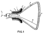
- a self-converging colour display device comprises a cathode-ray tube fitted with an evacuated glass envelope 6 and an array of phosphors representing various colours, these phosphors being arranged at one of the ends of the envelope, forming a display screen 9, and a set of electron guns 7 arranged at a second end of the envelope.
- the set of electron guns is arranged so as to produce three electron beams 12 aligned horizontally so as to excite, respectively, one of the various colour phosphors.
- the electron beams scan the entire surface of the screen by means of a deflection system 1, or deflector, which is placed on the neck 8 of the tube and comprises a pair of horizontal deflection coils 3, a pair of vertical deflection coils 4, these being isolated from each other by a separator 2, and a core 5 made of ferromagnetic material intended to concentrate the field at the point where it is designed to act.
- a deflection system 1 or deflector, which is placed on the neck 8 of the tube and comprises a pair of horizontal deflection coils 3, a pair of vertical deflection coils 4, these being isolated from each other by a separator 2, and a core 5 made of ferromagnetic material intended to concentrate the field at the point where it is designed to act.
- each vertical deflection coil of the deflector 1 is in the shape of a saddle and has a portion 19 called a rear end bundle, close to the electron gun 7 and preferably extending in a direction parallel to the Z axis.
- a second portion 29, called the front end bundle, of the coil 10 is close to the display screen 9 and is incurvate, on moving away from the Z axis, in a direction generally transverse to the latter.
- the front end bundle 29 of the saddle-shaped coil 4 is connected to the rear end bundle 19 by groups of lateral conductors 120.
- the bundles 19 and 29 as well as the lateral groups of conductors 120 generally arranged symmetrically with respect to an XZ plane, define a main window 18.
- the region over which the window 18 extends is called the intermediate region 24
- the region over which the conductors making up the front bundle fan out is called the exit region 23
- that region of the coil which lies to the rear of the window 18 making up the rear bundle is called the entry region 25.
- Figure 2 illustrates a "vertical blue wave” aberration that the present invention aims to minimize.
- a test pattern is displayed on one quarter of the screen and illustrates the shift of the images created by the red beam 30 and the blue beam 31.
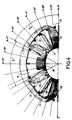
- FIG. 3 illustrates, by means of a side view, one of the pairs of the saddle-shaped coils 4 implementing one aspect of the invention.
- Each winding turn is formed by a loop of conductor wire generally having the shape of a saddle.
- a saddle-shaped coil as described above and shown in Figure 4 may be wound with a fine copper wire, the wire being covered with an electrical insulation and with a thermosetting adhesive.
- the winding is carried out in a winder which winds the saddle-shaped coil essentially in its final shape and which introduces spaces 21, 21', 21'', etc. during the winding process. The shapes and the locations of these spaces are defined by retractable pins 22 or by inserts 28.
- each saddle-shaped coil is held in place in a jig and pressure applied to it so as to obtain the required mechanical dimensions.
- a current passes through the wire so as to soften the thermosetting resin, which is then cooled so as to bond the wires together and to form a self-supporting saddle-shaped coil.
- the self-converging deflectors have vertical deflection fields whose intensity has a barrel-shaped distribution. Moreover, it is known that the convergence errors between the red and blue beams are corrected in the intermediate region 24 of the vertical deflection coils by varying the position of the conductors of the lateral harnesses in order to modify the potential harmonics of order 3 and/or 5. These considerations have hitherto made it possible to design vertical deflection coils with as narrow as possible a main window, which design is particularly suited when the "vertical blue wave" is equal or close to zero; however, this coil structure does not provide a solution if the red/blue convergence errors vary in a non-linear manner along the vertical edge of the image between the 2 o'clock and 3 o'clock points.
- the invention resides in the modification of the 7 th and 9 th potential harmonics in the front region of the main window 18, near the exit region 23.
- Figure 4 illustrates one embodiment of the invention in which the vertical deflection coil is shown front on.
- the front of the main window 18 of the vertical deflection coil is therefore enlarged with respect to the prior art so that, near the transition region between the parts 23 and 24 of the coil, at least 98% of the conductors of the lateral harnesses lie within a radial angular aperture ⁇ m of less than 71°, ⁇ m being measured with respect to the plane of separation, YZ, of the two vertical deflection coils.
- ⁇ m is preferably chosen within a range lying between 60° and 71°, which is equivalent to saying that in the region close to the front bundle, the window (18) extends over a radial angular aperture ⁇ of between 38° and 60°.
- the conductors of the lateral harnesses lie, at the front of the main window 18, within a radial angular aperture ⁇ m of 67.5°.
- the main window may contain, in its front part, a small fraction of lateral conductors without thereby affecting the red/blue convergence characteristics along the vertical edge of the image.
- the number of turns lying within the main window 18 must be small, at most about 2% of the number of turns making up the coil.
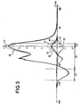
- the 3 rd , 5 th , 7 th and 9 th harmonics of the vertical deflection potential of the deflection field of the coil according to the prior art are labelled 41, 51, 61 and 71, respectively, and the 3 rd , 5 th , 7 th and 9 th harmonics of the vertical deflection coil of the same embodiment of the invention as previously are labelled 40, 50, 60 and 70, respectively.
- the amplitude of the 7 th -order harmonic, initially greater than the 9 th -order harmonic has been greatly reduced so as to become of the same order of magnitude, or even substantially less than the said 9 th harmonic, the said 7 th and 9 th harmonics remaining of opposite sign.
Landscapes
- Video Image Reproduction Devices For Color Tv Systems (AREA)
Applications Claiming Priority (2)
| Application Number | Priority Date | Filing Date | Title |
|---|---|---|---|
| FR9910897 | 1999-08-30 | ||
| FR9910897A FR2797994B1 (fr) | 1999-08-30 | 1999-08-30 | Unite de deflexion pour tube a rayons cathodiques autoconvergents comportant des bobines de deviation verticales en forme de selle |
Publications (2)
| Publication Number | Publication Date |
|---|---|
| EP1081737A1 EP1081737A1 (en) | 2001-03-07 |
| EP1081737B1 true EP1081737B1 (en) | 2005-05-25 |
Family
ID=9549417
Family Applications (1)
| Application Number | Title | Priority Date | Filing Date |
|---|---|---|---|
| EP00402339A Expired - Lifetime EP1081737B1 (en) | 1999-08-30 | 2000-08-23 | Deflection unit for self-converging cathode-ray tubes, comprising saddle-shaped vertical deflection coils |
Country Status (9)
| Country | Link |
|---|---|
| US (1) | US6577053B1 (ja) |
| EP (1) | EP1081737B1 (ja) |
| JP (1) | JP2001126639A (ja) |
| KR (1) | KR100825144B1 (ja) |
| CN (1) | CN1286141C (ja) |
| DE (1) | DE60020312T2 (ja) |
| FR (1) | FR2797994B1 (ja) |
| MX (1) | MXPA00008464A (ja) |
| MY (1) | MY119964A (ja) |
Families Citing this family (3)
| Publication number | Priority date | Publication date | Assignee | Title |
|---|---|---|---|---|
| FR2791468B1 (fr) * | 1999-03-24 | 2001-05-11 | Thomson Tubes & Displays | Unite de deviation pour tube a rayons cathodiques autoconvergents a differentiel de trapeze reduit |
| US20040000858A1 (en) * | 2002-06-28 | 2004-01-01 | Samsung Electro Mechanics Co., Ltd. | Deflection yoke |
| US7838596B2 (en) | 2005-09-16 | 2010-11-23 | Eastman Chemical Company | Late addition to effect compositional modifications in condensation polymers |
Family Cites Families (10)
| Publication number | Priority date | Publication date | Assignee | Title |
|---|---|---|---|---|
| DE976695C (de) * | 1943-09-08 | 1964-03-05 | Philips Nv | Ablenkspulenanordnung fuer Kathodenstrahlroehren |
| US2562395A (en) * | 1949-02-23 | 1951-07-31 | Motorola Inc | Anastigmatic deflection yoke |
| GB1329412A (en) * | 1969-09-18 | 1973-09-05 | Science Res Council | Electrical coils for generating magnetic fields |
| US4039988A (en) * | 1973-07-23 | 1977-08-02 | U.S. Philips Corporation | Deflection coil having sections with minimum winding density portions and spaces |
| NL8802641A (nl) * | 1988-10-27 | 1990-05-16 | Philips Nv | Werkwijze voor het vervaardigen van een zadelvormige afbuigspoel voor een beeldweergeefbuis en afbuigsysteem met zadelvormige afbuigspoelen. |
| ATE154468T1 (de) * | 1989-10-31 | 1997-06-15 | Thomson Tubes & Displays | Anzeigevorrichtung mit einer farbbildröhre |
| FR2689679A1 (fr) * | 1992-04-07 | 1993-10-08 | Thomson Tubes & Displays | Dispositif de déflexion des faisceaux d'électrons pour tubes à rayons cathodiques autoconvergent et corrigé en géométrie. |
| FR2757678B1 (fr) * | 1996-12-20 | 1999-01-29 | Thomson Tubes & Displays | Unite de deviation pour tube a rayons cathodiques autoconvergents comportant des bobines de deviation en forme de selle |
| FR2757681B1 (fr) * | 1996-12-20 | 1999-01-29 | Thomson Tubes & Displays | Systeme de deviation pour tube a rayons cathodiques adapte au controle de la geometrie nord/sud de l'image |
| KR100242172B1 (ko) * | 1997-08-30 | 2000-02-01 | 김영남 | 음극선관용 필름형 새들타입 편향부재 및 이를 이용한 새들형 편향코일 제조방법 |
-
1999
- 1999-08-30 FR FR9910897A patent/FR2797994B1/fr not_active Expired - Fee Related
-
2000
- 2000-08-18 US US09/641,602 patent/US6577053B1/en not_active Expired - Fee Related
- 2000-08-23 EP EP00402339A patent/EP1081737B1/en not_active Expired - Lifetime
- 2000-08-23 DE DE60020312T patent/DE60020312T2/de not_active Expired - Fee Related
- 2000-08-28 KR KR1020000050024A patent/KR100825144B1/ko not_active IP Right Cessation
- 2000-08-29 MX MXPA00008464A patent/MXPA00008464A/es unknown
- 2000-08-29 JP JP2000258364A patent/JP2001126639A/ja active Pending
- 2000-08-29 MY MYPI20003964A patent/MY119964A/en unknown
- 2000-08-30 CN CNB001268961A patent/CN1286141C/zh not_active Expired - Fee Related
Also Published As
| Publication number | Publication date |
|---|---|
| KR100825144B1 (ko) | 2008-04-24 |
| EP1081737A1 (en) | 2001-03-07 |
| US6577053B1 (en) | 2003-06-10 |
| MXPA00008464A (es) | 2002-07-22 |
| DE60020312D1 (de) | 2005-06-30 |
| CN1286141C (zh) | 2006-11-22 |
| JP2001126639A (ja) | 2001-05-11 |
| FR2797994A1 (fr) | 2001-03-02 |
| KR20010021440A (ko) | 2001-03-15 |
| FR2797994B1 (fr) | 2001-12-07 |
| CN1312580A (zh) | 2001-09-12 |
| MY119964A (en) | 2005-08-30 |
| DE60020312T2 (de) | 2006-05-04 |
Similar Documents
| Publication | Publication Date | Title |
|---|---|---|
| EP0425747B1 (en) | Color picture tube display device | |
| EP0853329B1 (en) | Deflection unit for self-converging cathode-ray tubes which includes deflection coils in the shape of a saddle | |
| US6150910A (en) | Deflection yoke with geometry distortion correction | |
| EP0519505B1 (en) | Deflection yoke apparatus | |
| US5418422A (en) | Combination of display tube and deflection unit comprising line deflection coils of the semi-saddle type with a gun-sided extension | |
| EP1081737B1 (en) | Deflection unit for self-converging cathode-ray tubes, comprising saddle-shaped vertical deflection coils | |
| US6690105B1 (en) | Deflection coil of a deflection yoke | |
| EP0490004A1 (en) | Field harmonic enhancer in a deflection yoke | |
| EP0569079B1 (en) | Combination of display tube and deflection unit comprising line deflection coils of the semi-saddle type with a gun-sided extension | |
| US7005788B2 (en) | Magnetic device for correcting image geometry defects for cathode-ray tubes | |
| US7411342B1 (en) | Deflection unit for self-converging cathode-ray tubes with reduced trapezoid differential | |
| US6630803B1 (en) | Color display device having quadrupole convergence coils | |
| EP1105911A1 (en) | Color display device having quadrupole convergence coils | |
| EP1105912A1 (en) | Color display device having quadrupole convergence coils | |
| MXPA99005756A (en) | A saddle shaped deflection winding having a winding space within a predetermined angular range | |
| MXPA99005755A (es) | Un yugo de desviacion con correccion de distorsion de geometria |
Legal Events
| Date | Code | Title | Description |
|---|---|---|---|
| PUAI | Public reference made under article 153(3) epc to a published international application that has entered the european phase |
Free format text: ORIGINAL CODE: 0009012 |
|
| AK | Designated contracting states |
Kind code of ref document: A1 Designated state(s): DE FR GB IT |
|
| AX | Request for extension of the european patent |
Free format text: AL;LT;LV;MK;RO;SI |
|
| 17P | Request for examination filed |
Effective date: 20010814 |
|
| AKX | Designation fees paid |
Free format text: DE FR GB IT |
|
| 17Q | First examination report despatched |
Effective date: 20040203 |
|
| GRAP | Despatch of communication of intention to grant a patent |
Free format text: ORIGINAL CODE: EPIDOSNIGR1 |
|
| GRAS | Grant fee paid |
Free format text: ORIGINAL CODE: EPIDOSNIGR3 |
|
| GRAA | (expected) grant |
Free format text: ORIGINAL CODE: 0009210 |
|
| AK | Designated contracting states |
Kind code of ref document: B1 Designated state(s): DE FR GB IT |
|
| REG | Reference to a national code |
Ref country code: GB Ref legal event code: FG4D |
|
| REF | Corresponds to: |
Ref document number: 60020312 Country of ref document: DE Date of ref document: 20050630 Kind code of ref document: P |
|
| ET | Fr: translation filed | ||
| PLBE | No opposition filed within time limit |
Free format text: ORIGINAL CODE: 0009261 |
|
| STAA | Information on the status of an ep patent application or granted ep patent |
Free format text: STATUS: NO OPPOSITION FILED WITHIN TIME LIMIT |
|
| 26N | No opposition filed |
Effective date: 20060228 |
|
| PGFP | Annual fee paid to national office [announced via postgrant information from national office to epo] |
Ref country code: DE Payment date: 20080825 Year of fee payment: 9 |
|
| PGFP | Annual fee paid to national office [announced via postgrant information from national office to epo] |
Ref country code: FR Payment date: 20080822 Year of fee payment: 9 Ref country code: IT Payment date: 20080828 Year of fee payment: 9 |
|
| PGFP | Annual fee paid to national office [announced via postgrant information from national office to epo] |
Ref country code: GB Payment date: 20080718 Year of fee payment: 9 |
|
| GBPC | Gb: european patent ceased through non-payment of renewal fee |
Effective date: 20090823 |
|
| REG | Reference to a national code |
Ref country code: FR Ref legal event code: ST Effective date: 20100430 |
|
| PG25 | Lapsed in a contracting state [announced via postgrant information from national office to epo] |
Ref country code: FR Free format text: LAPSE BECAUSE OF NON-PAYMENT OF DUE FEES Effective date: 20090831 Ref country code: DE Free format text: LAPSE BECAUSE OF NON-PAYMENT OF DUE FEES Effective date: 20100302 |
|
| PG25 | Lapsed in a contracting state [announced via postgrant information from national office to epo] |
Ref country code: GB Free format text: LAPSE BECAUSE OF NON-PAYMENT OF DUE FEES Effective date: 20090823 |
|
| PG25 | Lapsed in a contracting state [announced via postgrant information from national office to epo] |
Ref country code: IT Free format text: LAPSE BECAUSE OF NON-PAYMENT OF DUE FEES Effective date: 20090823 |