EP1081463A2 - Wegmesssystem - Google Patents
Wegmesssystem Download PDFInfo
- Publication number
- EP1081463A2 EP1081463A2 EP00115373A EP00115373A EP1081463A2 EP 1081463 A2 EP1081463 A2 EP 1081463A2 EP 00115373 A EP00115373 A EP 00115373A EP 00115373 A EP00115373 A EP 00115373A EP 1081463 A2 EP1081463 A2 EP 1081463A2
- Authority
- EP
- European Patent Office
- Prior art keywords
- guide
- measuring system
- position measuring
- scanning device
- guide elements
- Prior art date
- Legal status (The legal status is an assumption and is not a legal conclusion. Google has not performed a legal analysis and makes no representation as to the accuracy of the status listed.)
- Granted
Links
- 238000006073 displacement reaction Methods 0.000 title claims description 8
- 230000008878 coupling Effects 0.000 claims abstract description 77
- 238000010168 coupling process Methods 0.000 claims abstract description 77
- 238000005859 coupling reaction Methods 0.000 claims abstract description 77
- 238000004519 manufacturing process Methods 0.000 claims description 3
- 238000005259 measurement Methods 0.000 abstract description 11
- 229910000639 Spring steel Inorganic materials 0.000 description 2
- 238000005452 bending Methods 0.000 description 1
- 238000006243 chemical reaction Methods 0.000 description 1
- 230000000694 effects Effects 0.000 description 1
- 238000009434 installation Methods 0.000 description 1
- 238000000034 method Methods 0.000 description 1
- 230000003287 optical effect Effects 0.000 description 1
- 238000003825 pressing Methods 0.000 description 1
- 230000003134 recirculating effect Effects 0.000 description 1
- 230000007704 transition Effects 0.000 description 1
Images

Classifications
-
- G—PHYSICS
- G01—MEASURING; TESTING
- G01D—MEASURING NOT SPECIALLY ADAPTED FOR A SPECIFIC VARIABLE; ARRANGEMENTS FOR MEASURING TWO OR MORE VARIABLES NOT COVERED IN A SINGLE OTHER SUBCLASS; TARIFF METERING APPARATUS; MEASURING OR TESTING NOT OTHERWISE PROVIDED FOR
- G01D5/00—Mechanical means for transferring the output of a sensing member; Means for converting the output of a sensing member to another variable where the form or nature of the sensing member does not constrain the means for converting; Transducers not specially adapted for a specific variable
- G01D5/26—Mechanical means for transferring the output of a sensing member; Means for converting the output of a sensing member to another variable where the form or nature of the sensing member does not constrain the means for converting; Transducers not specially adapted for a specific variable characterised by optical transfer means, i.e. using infrared, visible, or ultraviolet light
- G01D5/32—Mechanical means for transferring the output of a sensing member; Means for converting the output of a sensing member to another variable where the form or nature of the sensing member does not constrain the means for converting; Transducers not specially adapted for a specific variable characterised by optical transfer means, i.e. using infrared, visible, or ultraviolet light with attenuation or whole or partial obturation of beams of light
- G01D5/34—Mechanical means for transferring the output of a sensing member; Means for converting the output of a sensing member to another variable where the form or nature of the sensing member does not constrain the means for converting; Transducers not specially adapted for a specific variable characterised by optical transfer means, i.e. using infrared, visible, or ultraviolet light with attenuation or whole or partial obturation of beams of light the beams of light being detected by photocells
- G01D5/347—Mechanical means for transferring the output of a sensing member; Means for converting the output of a sensing member to another variable where the form or nature of the sensing member does not constrain the means for converting; Transducers not specially adapted for a specific variable characterised by optical transfer means, i.e. using infrared, visible, or ultraviolet light with attenuation or whole or partial obturation of beams of light the beams of light being detected by photocells using displacement encoding scales
- G01D5/34746—Linear encoders
- G01D5/34753—Carriages; Driving or coupling means
Definitions
- the invention relates to a position measuring system for determining the position of two relatively movable components according to the preamble of the claim 1.
- a guide device for the scanning device for the carrier body of the measuring graduation to be provided and the scanning device via a coupling unit, which comprises a coupling rod and two ball joints, articulated with the to connect the second machine part.
- a coupling unit which comprises a coupling rod and two ball joints, articulated with the to connect the second machine part.
- the invention is based on the object of a displacement measuring system at the beginning mentioned type with regard to the adjustability of the length of the coupling element to improve.
- the sliding guide can be an essentially rigid clamping element include, e.g. in the form of a clamping screw or an eccentric, which for Production of the clamp connection acts on one of the guide elements.
- the sliding guide can have an elastic section and means for deforming this section to produce the Clamp connection, e.g. in the form of a set screw or an eccentric, include. That means a clamping element in the form of a set screw or an eccentric acts on the elastically deformable section, and so on indirectly to establish the clamp connection.
- the elastically deformable section can be part of one of the two Guide elements that are the other guide element with this section embraces.
- this has the one guide element has a passage in which the other guide element is guided, and is with an extending up to the passage Provide slot so that the cross section of the passage can be changed is and thereby the desired clamping effect can be generated can.
- the guide element guided in the passage can act in particular a section of the coupling element itself.
- the sliding guide can both on the scanner and on arranged the second component facing end of the coupling element be, and there can also be one at both ends of the coupling element Sliding guide be present. It is also possible to use the sliding guide to be arranged in the central area of the coupling element.
- the sliding guide is however preferably provided on one of the end sections of the coupling element, in order not to impair its flexibility and thus the Establish a simple articulated connection between the scanner and to enable the second component.
- FIGS. 1a and 1b A detail is shown in two different views in FIGS. 1a and 1b a distance measuring system (length measuring system) is shown, which is used for determination the position of two relatively movable along a measurement direction V to each other Machine components is suitable.
- a distance measuring system length measuring system
- the carrier body 1 is in position with a first one B indicated machine part of a machine tool.
- the scale 10 runs parallel to the direction of extension thereof Machine part.
- a scanning device 2 is guided, which a second, associated with the first machine part movable machine part is.
- the scanning device comprises 2 a scanning carriage 23, which with respect to the carrier body 1 along the Measuring direction V is displaceable and the one scanning head 24 for scanning the measuring division of the scale 10 carries.
- the scanning head 24 can e.g. a Light source, a lens system and photo elements assigned to the light source include.
- the present invention is independent of which physical principle of scanning the scale 10 by means of Readhead 24 is based.
- the connecting plate 25 and the associated guide device 12 becomes a defined one Guidance of the scanning device 2 along the scale 10 reached, regardless of whether the two machine parts, their relative location to be determined with the position measuring system, in the operation of the machine tool actually move exactly parallel to each other.
- the effective length of the coupling rod 3 can be changed.
- the length is the effective length of the coupling rod 3 the coupling rod 3 between the connecting plate 25 and the fastening piece 4 understood.
- a slot 45 extends through the Guide element 40 up to a lateral edge of the guide element.
- the guide element 40 is in the region of the passage 41 elastically deformable.
- a bore extends in the guide element 40 transversely to the slot 45 46, which opens into the slot 45 and on the other side of the Slot 45 passes into a threaded bore 47.
- the sliding guide assigned to the connecting plate 25 opens 3, 50 two different ways of arranging the fastening piece 4 with respect to the scanning device 2.
- the fastening piece 4 in two different, opposite positions with respect to the scanner 2, as in Figure 1a in dashed lines through the Representation of the coupling rod 3 and the mounting piece 4 in one second possible position is indicated.
- Additional markings can be provided to prevent the Coupling rod 3 and the associated guide element 40 or 50 so far against each other that the coupling rod in the respective Guide element 40, 50 can no longer be held securely.
- the guide element 40 integrated in the fastening piece 4 is e.g. then the case when the coupling rod 3 with its end portion is no longer located within the constriction 43 of the passage 41.
- the diameter of the ring on the fastening piece 4th facing end of the coupling rod 3 should be such that it is smaller than the inside diameter of the outer portions 42 of the passage 41, but larger than the inside diameter of the constriction 43.
Landscapes
- Physics & Mathematics (AREA)
- General Physics & Mathematics (AREA)
- Length Measuring Devices With Unspecified Measuring Means (AREA)
- A Measuring Device Byusing Mechanical Method (AREA)
Abstract
Description
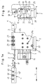
- Figur 1a
- eine Draufsicht auf ein Wegmesssystem einer Abtasteinrichtung, die über eine Koppelstange gelenkig mit einem Maschinenteil verbindbar ist;
- Figur 1b
- eine Seitenansicht des Wegmesssystems aus Figur 1a ohne Koppelstange;
- Figur 2a
- einen Längsschnitt durch ein Führungselement einer Schiebeführung, mittels der die effektive Länge der in Figur 1a dargestellten Koppelstange einstellbar ist;
- Figur 2b
- eine Draufsicht auf das in Figur 2a in einem Längsschnitt dargestellte Führungselement;
- Figur 2c
- einen Querschnitt entlang der Linie IIc in Figur 2b;
- Figur 2d
- einen Querschnitt entlang der Linie IId in Figur 2b;
- Figur 2e, 2f
- zwei weitere Ansichten des Führungselementes.
Claims (15)
- Wegmesssystem zur Erfassung der Lage zweier relativ zueinander beweglicher Bauteile, insbesondere Maschinenteile, mitdadurch gekennzeichnet,einer Messteilung (10), die einem ersten der beiden Bauteile zugeordnet ist und eine Messrichtung (V) definiert,einer Abtasteinrichtung zur Abtastung der Messteilung (10), die dem zweiten der beiden Bauteile zugeordnet ist,einer Führungseinrichtung (12), mit der die Abtasteinrichtung (2) in Messrichtung (V) verschieblich entlang der Messteilung (10) geführt ist,einem längserstreckten Koppelelement (3), über das die Abtasteinrichtung (2) mit dem zweiten Bauteil verbindbar ist, undeiner Längsverstellung zur Anpassung der effektiven Länge des Koppelelementes (3) an die Lage des zweiten Bauteiles bezüglich der Abtasteinrichtung (2),
dass die Längsverstellung eine Schiebeführung (3, 40; 3, 50) mit zwei in Erstreckungsrichtung (L) des Koppelelementes (3) zueinander verschieblichen und nach einem Verschieben aneinander fixierbaren Führungselementen (3, 40, 50) aufweist. - Wegmesssystem nach Anspruch 1, dadurch gekennzeichnet, dass die Führungselemente (3, 40, 50) durch eine Klemmverbindung fixierbar sind.
- Wegmesssystem nach Anspruch 2, dadurch gekennzeichnet, dass die Schiebeführung (3, 40; 3, 50) ein Klemmelement, insbesondere in Form einer Schraube (28, 48) oder eines Exzenters, aufweist, das zur Herstellung der Klemmverbindung auf eines der Führungselemente (3, 40, 50) einwirken kann.
- Wegmesssystem nach Anspruch 2 oder 3, dadurch gekennzeichnet, dass die Schiebeführung (3, 40; 3, 50) einen elastisch ausgebildeten Abschnitt umfasst, der zur Herstellung der Klemmverbindung deformierbar ist.
- Wegmesssystem nach Anspruch 4, dadurch gekennzeichnet, dass die Schiebeführung (3, 40; 3, 50) eine Stellschraube (28, 48) aufweist, mittels der der elastisch ausgebildete Abschnitt deformierbar ist.
- Wegmesssystem nach Anspruch 4 oder 5, dadurch gekennzeichnet, dass eines der Führungselemente (40, 50) das andere Führungselement (3) mit einem elastisch deformierbaren Abschnitt umgreift.
- Wegmesssystem nach einem der vorhergehenden Ansprüche, dadurch gekennzeichnet, dass eines der Führungselemente (40, 50) einen Durchgang (41, 51) aufweist, in dem das andere Führungselement (3) geführt ist.
- Wegmesssystem nach Anspruch 6 und 7, dadurch gekennzeichnet, dass das eine Führungselement (40, 50) mit einem sich bis zu dem Durchgang (41, 51) erstreckenden Schlitz (45, 55) versehen ist, so dass durch Deformation des einen Führungselementes (40, 50) im Bereich des Schlitzes (45, 55) der Querschnitt des Durchganges (41, 51) veränderbar ist.
- Wegmesssystem nach einem der vorhergehenden Ansprüche, dadurch gekennzeichnet, dass eines der Führungselemente (3) durch das längserstreckte Koppelelement (3) gebildet wird, das als Koppelstange ausgebildet ist.
- Wegmesssystem nach einem der vorhergehenden Ansprüche, dadurch gekennzeichnet, dass die Abtasteinrichtung (2) über das längserstreckte Koppelelement (3) gelenkig mit dem zweiten Bauteil verbunden ist.
- Wegmesssystem nach Anspruch 9 und 10, dadurch gekennzeichnet, dass die Koppelstange (3) biegbar ausgebildet ist.
- Wegmesssystem nach einem der vorhergehenden Ansprüche, dadurch gekennzeichnet, dass zumindest eines der Führungselemente (3) Markierungen aufweist, anhand derer die Lage der beiden Führungselemente (3, 40, 50) zueinander bestimmbar ist.
- Wegmesssystem nach einem der vorhergehenden Ansprüche, dadurch gekennzeichnet, dass zumindest eines der Führungselemente (3) mindestens einen Anschlag (31, 32) aufweist, durch den der Verschiebeweg der beiden Führungselemente (3, 40, 50) zueinander begrenzt wird.
- Wegmesssystem nach einem der vorhergehenden Ansprüche, dadurch gekennzeichnet, dass zwei Schiebeführungen (3, 40; 3, 50) vorgesehen sind, wobei das längserstreckte Koppelelement (3) über eine Schiebeführung (3, 50) mit der Abtasteinrichtung (2) und über die andere Schiebeführung (3, 40) mit dem zweiten Bauteil verbunden ist.
- Wegmesssystem nach einem der vorhergehenden Ansprüche, dadurch gekennzeichnet, dass die Führungseinrichtung (12), mit der die Abtasteinrichtung (2) verschieblich entlang der Messteilung geführt ist, an dem Trägerkörper (1) vorgesehen ist.
Applications Claiming Priority (2)
| Application Number | Priority Date | Filing Date | Title |
|---|---|---|---|
| DE19943729 | 1999-09-03 | ||
| DE1999143729 DE19943729A1 (de) | 1999-09-03 | 1999-09-03 | Wegmeßsystem |
Publications (3)
| Publication Number | Publication Date |
|---|---|
| EP1081463A2 true EP1081463A2 (de) | 2001-03-07 |
| EP1081463A3 EP1081463A3 (de) | 2004-01-07 |
| EP1081463B1 EP1081463B1 (de) | 2007-11-28 |
Family
ID=7921795
Family Applications (1)
| Application Number | Title | Priority Date | Filing Date |
|---|---|---|---|
| EP20000115373 Expired - Lifetime EP1081463B1 (de) | 1999-09-03 | 2000-07-15 | Wegmesssystem |
Country Status (3)
| Country | Link |
|---|---|
| EP (1) | EP1081463B1 (de) |
| DE (2) | DE19943729A1 (de) |
| ES (1) | ES2296587T3 (de) |
Families Citing this family (2)
| Publication number | Priority date | Publication date | Assignee | Title |
|---|---|---|---|---|
| US6518565B1 (en) * | 2000-09-20 | 2003-02-11 | Eaton Corporation | Sensor assembly |
| DE10250094B4 (de) * | 2002-10-26 | 2010-07-22 | Dr. Johannes Heidenhain Gmbh | Messsystem mit einer Koppelstange |
Citations (3)
| Publication number | Priority date | Publication date | Assignee | Title |
|---|---|---|---|---|
| DE3530776A1 (de) * | 1984-08-31 | 1986-03-06 | Sony Magnescale Inc., Tokio/Tokyo | Geradlinige messskala |
| DE9317437U1 (de) * | 1993-11-15 | 1994-01-20 | Jung Gmbh K | Maschine, insbesondere Werkzeugmaschine |
| DE4306951A1 (de) * | 1993-03-05 | 1994-09-08 | Balluff Gebhard Feinmech | Wegmeßsystem |
Family Cites Families (6)
| Publication number | Priority date | Publication date | Assignee | Title |
|---|---|---|---|---|
| DE2712096C2 (de) * | 1977-03-19 | 1979-01-04 | Dr. Johannes Heidenhain Gmbh, 8225 Traunreut | Gekapselte Meßeinrichtung |
| AT395070B (de) * | 1983-11-22 | 1992-09-10 | Emr Elektronische Mess Und Reg | Laengenmesseinrichtung, insbesondere gekapselte laengenmesseinrichtung |
| DE4200597A1 (de) * | 1992-01-13 | 1993-07-15 | Zeiss Carl Jena Gmbh | Einrichtung zum messen und einstellen von laengen mit einem, einen bandfoermigen teilungstraeger umfassenden wegmesssystem |
| DE4438079A1 (de) * | 1994-10-25 | 1996-05-02 | Heidenhain Gmbh Dr Johannes | Führung |
| DE19543647C2 (de) * | 1995-11-23 | 2000-05-04 | Heidenhain Gmbh Dr Johannes | Längenmeßeinrichtung zur Messung der Relativlage zweier Objekte |
| DE19747356A1 (de) * | 1997-10-27 | 1999-04-29 | Heidenhain Gmbh Dr Johannes | Längenmeßeinrichtung und Maschine mit einer Längenmeßeinrichtung |
-
1999
- 1999-09-03 DE DE1999143729 patent/DE19943729A1/de not_active Withdrawn
-
2000
- 2000-07-15 ES ES00115373T patent/ES2296587T3/es not_active Expired - Lifetime
- 2000-07-15 EP EP20000115373 patent/EP1081463B1/de not_active Expired - Lifetime
- 2000-07-15 DE DE50014810T patent/DE50014810D1/de not_active Expired - Lifetime
Patent Citations (3)
| Publication number | Priority date | Publication date | Assignee | Title |
|---|---|---|---|---|
| DE3530776A1 (de) * | 1984-08-31 | 1986-03-06 | Sony Magnescale Inc., Tokio/Tokyo | Geradlinige messskala |
| DE4306951A1 (de) * | 1993-03-05 | 1994-09-08 | Balluff Gebhard Feinmech | Wegmeßsystem |
| DE9317437U1 (de) * | 1993-11-15 | 1994-01-20 | Jung Gmbh K | Maschine, insbesondere Werkzeugmaschine |
Also Published As
| Publication number | Publication date |
|---|---|
| DE50014810D1 (de) | 2008-01-10 |
| EP1081463A3 (de) | 2004-01-07 |
| DE19943729A1 (de) | 2001-03-08 |
| ES2296587T3 (es) | 2008-05-01 |
| EP1081463B1 (de) | 2007-11-28 |
Similar Documents
| Publication | Publication Date | Title |
|---|---|---|
| EP1820982B1 (de) | Linearführungseinrichtung mit Vorspannungseinstelleinrichtung | |
| EP0836078B1 (de) | Massstab einer Längenmesseinrichtung sowie Verfahren zur Anbringung eines Massstabs | |
| DE19940628C1 (de) | Schaltschiene mit daran befestigter Schaltgabel für Kraftfahrzeug-Schaltgetriebe | |
| EP0918174A2 (de) | Lineareinheit mit motorischem Stellantrieb | |
| DE19918654A1 (de) | Sicherungsvorrichtung für den Transport und die Montage einer Meßeinrichtung | |
| DE3026350A1 (de) | Messinstrument zur ueberpruefung der abmessungen von mechanischen teilen | |
| DE19956833B4 (de) | Winkelmeßsystem | |
| EP1081463B1 (de) | Wegmesssystem | |
| EP4030147B1 (de) | Längenmesseinrichtung | |
| EP3156564A1 (de) | Koppelstift mit einstellbarer länge | |
| EP1522826A1 (de) | Sicherungsvorrichtung für den Transport und die Montage einer Messeinrichtung | |
| DE102009039591A1 (de) | Haltevorrichtung und Halterung | |
| DE10214426B4 (de) | Längenmesseinrichtung und Linearführungseinheit | |
| DE2810637C2 (de) | Einstellvorrichtung zum Ausrichten der Achse einer Lichtleitfaser auf die Achse eines komplementären Körpers | |
| EP3308937B1 (de) | Kniehebel-schliesseinheit einer kunststoffverarbeitungsmaschine, insbesondere einer spritzgiessmaschine | |
| DE19701990C1 (de) | Vorrichtung zum Andrücken einer Laufrolle an eine Führungsschine | |
| DE10214427B4 (de) | Längenmeßeinrichtung und Linearführungseinheit | |
| EP1318088B1 (de) | Spannvorrichtung und Umsetzvorrichtung mit einer derartigen Spannvorrichtung | |
| DE102006024881B4 (de) | Führungseinheit für Linearführungen in Fahrzeugen, vorzugsweise in Kraftfahrzeugen | |
| EP0641623B1 (de) | Spanneinrichtung zum Halten von Werkstücken | |
| EP1473538B1 (de) | Messschlitten | |
| EP0611623B1 (de) | Aufspannvorrichtung | |
| DE10030325C2 (de) | Gleitstück | |
| DE10023568C2 (de) | Fokussiertrieb für optische Instrumente | |
| DE10330955A1 (de) | Positionsmessgerät und Verfahren zur Montage eines derartigen Positionsmessgerätes |
Legal Events
| Date | Code | Title | Description |
|---|---|---|---|
| PUAI | Public reference made under article 153(3) epc to a published international application that has entered the european phase |
Free format text: ORIGINAL CODE: 0009012 |
|
| AK | Designated contracting states |
Kind code of ref document: A2 Designated state(s): AT BE CH CY DE DK ES FI FR GB GR IE IT LI LU MC NL PT SE |
|
| AX | Request for extension of the european patent |
Free format text: AL;LT;LV;MK;RO;SI |
|
| PUAL | Search report despatched |
Free format text: ORIGINAL CODE: 0009013 |
|
| AK | Designated contracting states |
Kind code of ref document: A3 Designated state(s): AT BE CH CY DE DK ES FI FR GB GR IE IT LI LU MC NL PT SE |
|
| AX | Request for extension of the european patent |
Extension state: AL LT LV MK RO SI |
|
| 17P | Request for examination filed |
Effective date: 20040707 |
|
| AKX | Designation fees paid |
Designated state(s): AT BE CH CY DE DK ES FI FR GB GR IE IT LI LU MC NL PT SE |
|
| 17Q | First examination report despatched |
Effective date: 20061201 |
|
| GRAP | Despatch of communication of intention to grant a patent |
Free format text: ORIGINAL CODE: EPIDOSNIGR1 |
|
| RTI1 | Title (correction) |
Free format text: DISPLACEMENT MEASURING SYSTEM |
|
| GRAS | Grant fee paid |
Free format text: ORIGINAL CODE: EPIDOSNIGR3 |
|
| GRAA | (expected) grant |
Free format text: ORIGINAL CODE: 0009210 |
|
| AK | Designated contracting states |
Kind code of ref document: B1 Designated state(s): AT BE CH CY DE DK ES FI FR GB GR IE IT LI LU MC NL PT SE |
|
| REG | Reference to a national code |
Ref country code: GB Ref legal event code: FG4D Free format text: NOT ENGLISH |
|
| REG | Reference to a national code |
Ref country code: IE Ref legal event code: FG4D Free format text: LANGUAGE OF EP DOCUMENT: GERMAN |
|
| REG | Reference to a national code |
Ref country code: CH Ref legal event code: EP |
|
| REF | Corresponds to: |
Ref document number: 50014810 Country of ref document: DE Date of ref document: 20080110 Kind code of ref document: P |
|
| PG25 | Lapsed in a contracting state [announced via postgrant information from national office to epo] |
Ref country code: SE Free format text: LAPSE BECAUSE OF FAILURE TO SUBMIT A TRANSLATION OF THE DESCRIPTION OR TO PAY THE FEE WITHIN THE PRESCRIBED TIME-LIMIT Effective date: 20080228 Ref country code: NL Free format text: LAPSE BECAUSE OF FAILURE TO SUBMIT A TRANSLATION OF THE DESCRIPTION OR TO PAY THE FEE WITHIN THE PRESCRIBED TIME-LIMIT Effective date: 20071128 |
|
| NLV1 | Nl: lapsed or annulled due to failure to fulfill the requirements of art. 29p and 29m of the patents act | ||
| REG | Reference to a national code |
Ref country code: ES Ref legal event code: FG2A Ref document number: 2296587 Country of ref document: ES Kind code of ref document: T3 |
|
| PG25 | Lapsed in a contracting state [announced via postgrant information from national office to epo] |
Ref country code: FI Free format text: LAPSE BECAUSE OF FAILURE TO SUBMIT A TRANSLATION OF THE DESCRIPTION OR TO PAY THE FEE WITHIN THE PRESCRIBED TIME-LIMIT Effective date: 20071128 |
|
| ET | Fr: translation filed | ||
| GBV | Gb: ep patent (uk) treated as always having been void in accordance with gb section 77(7)/1977 [no translation filed] | ||
| PG25 | Lapsed in a contracting state [announced via postgrant information from national office to epo] |
Ref country code: DK Free format text: LAPSE BECAUSE OF FAILURE TO SUBMIT A TRANSLATION OF THE DESCRIPTION OR TO PAY THE FEE WITHIN THE PRESCRIBED TIME-LIMIT Effective date: 20071128 |
|
| PG25 | Lapsed in a contracting state [announced via postgrant information from national office to epo] |
Ref country code: PT Free format text: LAPSE BECAUSE OF FAILURE TO SUBMIT A TRANSLATION OF THE DESCRIPTION OR TO PAY THE FEE WITHIN THE PRESCRIBED TIME-LIMIT Effective date: 20080428 |
|
| REG | Reference to a national code |
Ref country code: IE Ref legal event code: FD4D |
|
| PLBE | No opposition filed within time limit |
Free format text: ORIGINAL CODE: 0009261 |
|
| STAA | Information on the status of an ep patent application or granted ep patent |
Free format text: STATUS: NO OPPOSITION FILED WITHIN TIME LIMIT |
|
| PG25 | Lapsed in a contracting state [announced via postgrant information from national office to epo] |
Ref country code: IE Free format text: LAPSE BECAUSE OF FAILURE TO SUBMIT A TRANSLATION OF THE DESCRIPTION OR TO PAY THE FEE WITHIN THE PRESCRIBED TIME-LIMIT Effective date: 20071128 |
|
| 26N | No opposition filed |
Effective date: 20080829 |
|
| PG25 | Lapsed in a contracting state [announced via postgrant information from national office to epo] |
Ref country code: GB Free format text: LAPSE BECAUSE OF FAILURE TO SUBMIT A TRANSLATION OF THE DESCRIPTION OR TO PAY THE FEE WITHIN THE PRESCRIBED TIME-LIMIT Effective date: 20071128 |
|
| PGFP | Annual fee paid to national office [announced via postgrant information from national office to epo] |
Ref country code: AT Payment date: 20080715 Year of fee payment: 9 |
|
| PG25 | Lapsed in a contracting state [announced via postgrant information from national office to epo] |
Ref country code: GR Free format text: LAPSE BECAUSE OF FAILURE TO SUBMIT A TRANSLATION OF THE DESCRIPTION OR TO PAY THE FEE WITHIN THE PRESCRIBED TIME-LIMIT Effective date: 20080229 |
|
| REG | Reference to a national code |
Ref country code: CH Ref legal event code: PL |
|
| PG25 | Lapsed in a contracting state [announced via postgrant information from national office to epo] |
Ref country code: MC Free format text: LAPSE BECAUSE OF NON-PAYMENT OF DUE FEES Effective date: 20080731 |
|
| PG25 | Lapsed in a contracting state [announced via postgrant information from national office to epo] |
Ref country code: LI Free format text: LAPSE BECAUSE OF NON-PAYMENT OF DUE FEES Effective date: 20080731 Ref country code: CH Free format text: LAPSE BECAUSE OF NON-PAYMENT OF DUE FEES Effective date: 20080731 |
|
| PG25 | Lapsed in a contracting state [announced via postgrant information from national office to epo] |
Ref country code: CY Free format text: LAPSE BECAUSE OF FAILURE TO SUBMIT A TRANSLATION OF THE DESCRIPTION OR TO PAY THE FEE WITHIN THE PRESCRIBED TIME-LIMIT Effective date: 20071128 |
|
| PG25 | Lapsed in a contracting state [announced via postgrant information from national office to epo] |
Ref country code: AT Free format text: LAPSE BECAUSE OF NON-PAYMENT OF DUE FEES Effective date: 20090715 Ref country code: LU Free format text: LAPSE BECAUSE OF NON-PAYMENT OF DUE FEES Effective date: 20080715 |
|
| PG25 | Lapsed in a contracting state [announced via postgrant information from national office to epo] |
Ref country code: BE Free format text: LAPSE BECAUSE OF NON-PAYMENT OF DUE FEES Effective date: 20080731 |
|
| PGFP | Annual fee paid to national office [announced via postgrant information from national office to epo] |
Ref country code: FR Payment date: 20140721 Year of fee payment: 15 |
|
| PGFP | Annual fee paid to national office [announced via postgrant information from national office to epo] |
Ref country code: IT Payment date: 20140729 Year of fee payment: 15 |
|
| PG25 | Lapsed in a contracting state [announced via postgrant information from national office to epo] |
Ref country code: IT Free format text: LAPSE BECAUSE OF NON-PAYMENT OF DUE FEES Effective date: 20150715 |
|
| REG | Reference to a national code |
Ref country code: FR Ref legal event code: ST Effective date: 20160331 |
|
| PG25 | Lapsed in a contracting state [announced via postgrant information from national office to epo] |
Ref country code: FR Free format text: LAPSE BECAUSE OF NON-PAYMENT OF DUE FEES Effective date: 20150731 |
|
| PGFP | Annual fee paid to national office [announced via postgrant information from national office to epo] |
Ref country code: ES Payment date: 20160715 Year of fee payment: 17 |
|
| PGFP | Annual fee paid to national office [announced via postgrant information from national office to epo] |
Ref country code: DE Payment date: 20170724 Year of fee payment: 18 |
|
| REG | Reference to a national code |
Ref country code: ES Ref legal event code: FD2A Effective date: 20181030 |
|
| REG | Reference to a national code |
Ref country code: DE Ref legal event code: R119 Ref document number: 50014810 Country of ref document: DE |
|
| PG25 | Lapsed in a contracting state [announced via postgrant information from national office to epo] |
Ref country code: ES Free format text: LAPSE BECAUSE OF NON-PAYMENT OF DUE FEES Effective date: 20170716 |
|
| PG25 | Lapsed in a contracting state [announced via postgrant information from national office to epo] |
Ref country code: DE Free format text: LAPSE BECAUSE OF NON-PAYMENT OF DUE FEES Effective date: 20190201 |