EP1081380A1 - Device and method for evacuation - Google Patents
Device and method for evacuation Download PDFInfo
- Publication number
- EP1081380A1 EP1081380A1 EP99921197A EP99921197A EP1081380A1 EP 1081380 A1 EP1081380 A1 EP 1081380A1 EP 99921197 A EP99921197 A EP 99921197A EP 99921197 A EP99921197 A EP 99921197A EP 1081380 A1 EP1081380 A1 EP 1081380A1
- Authority
- EP
- European Patent Office
- Prior art keywords
- vacuum pump
- rotational speed
- back pressure
- evacuating
- pump
- Prior art date
- Legal status (The legal status is an assumption and is not a legal conclusion. Google has not performed a legal analysis and makes no representation as to the accuracy of the status listed.)
- Withdrawn
Links
Images


Classifications
-
- F—MECHANICAL ENGINEERING; LIGHTING; HEATING; WEAPONS; BLASTING
- F04—POSITIVE - DISPLACEMENT MACHINES FOR LIQUIDS; PUMPS FOR LIQUIDS OR ELASTIC FLUIDS
- F04D—NON-POSITIVE-DISPLACEMENT PUMPS
- F04D27/00—Control, e.g. regulation, of pumps, pumping installations or pumping systems specially adapted for elastic fluids
- F04D27/02—Surge control
- F04D27/0261—Surge control by varying driving speed
-
- F—MECHANICAL ENGINEERING; LIGHTING; HEATING; WEAPONS; BLASTING
- F04—POSITIVE - DISPLACEMENT MACHINES FOR LIQUIDS; PUMPS FOR LIQUIDS OR ELASTIC FLUIDS
- F04B—POSITIVE-DISPLACEMENT MACHINES FOR LIQUIDS; PUMPS
- F04B37/00—Pumps having pertinent characteristics not provided for in, or of interest apart from, groups F04B25/00 - F04B35/00
- F04B37/06—Pumps having pertinent characteristics not provided for in, or of interest apart from, groups F04B25/00 - F04B35/00 for evacuating by thermal means
- F04B37/08—Pumps having pertinent characteristics not provided for in, or of interest apart from, groups F04B25/00 - F04B35/00 for evacuating by thermal means by condensing or freezing, e.g. cryogenic pumps
-
- F—MECHANICAL ENGINEERING; LIGHTING; HEATING; WEAPONS; BLASTING
- F04—POSITIVE - DISPLACEMENT MACHINES FOR LIQUIDS; PUMPS FOR LIQUIDS OR ELASTIC FLUIDS
- F04B—POSITIVE-DISPLACEMENT MACHINES FOR LIQUIDS; PUMPS
- F04B49/00—Control, e.g. of pump delivery, or pump pressure of, or safety measures for, machines, pumps, or pumping installations, not otherwise provided for, or of interest apart from, groups F04B1/00 - F04B47/00
- F04B49/06—Control using electricity
-
- F—MECHANICAL ENGINEERING; LIGHTING; HEATING; WEAPONS; BLASTING
- F04—POSITIVE - DISPLACEMENT MACHINES FOR LIQUIDS; PUMPS FOR LIQUIDS OR ELASTIC FLUIDS
- F04D—NON-POSITIVE-DISPLACEMENT PUMPS
- F04D19/00—Axial-flow pumps
- F04D19/02—Multi-stage pumps
- F04D19/04—Multi-stage pumps specially adapted to the production of a high vacuum, e.g. molecular pumps
-
- F—MECHANICAL ENGINEERING; LIGHTING; HEATING; WEAPONS; BLASTING
- F04—POSITIVE - DISPLACEMENT MACHINES FOR LIQUIDS; PUMPS FOR LIQUIDS OR ELASTIC FLUIDS
- F04B—POSITIVE-DISPLACEMENT MACHINES FOR LIQUIDS; PUMPS
- F04B2203/00—Motor parameters
- F04B2203/02—Motor parameters of rotating electric motors
- F04B2203/0209—Rotational speed
-
- Y—GENERAL TAGGING OF NEW TECHNOLOGICAL DEVELOPMENTS; GENERAL TAGGING OF CROSS-SECTIONAL TECHNOLOGIES SPANNING OVER SEVERAL SECTIONS OF THE IPC; TECHNICAL SUBJECTS COVERED BY FORMER USPC CROSS-REFERENCE ART COLLECTIONS [XRACs] AND DIGESTS
- Y02—TECHNOLOGIES OR APPLICATIONS FOR MITIGATION OR ADAPTATION AGAINST CLIMATE CHANGE
- Y02B—CLIMATE CHANGE MITIGATION TECHNOLOGIES RELATED TO BUILDINGS, e.g. HOUSING, HOUSE APPLIANCES OR RELATED END-USER APPLICATIONS
- Y02B30/00—Energy efficient heating, ventilation or air conditioning [HVAC]
- Y02B30/70—Efficient control or regulation technologies, e.g. for control of refrigerant flow, motor or heating
Definitions
- the present invention relates to an apparatus for and a method of evacuating a vacuum chamber (process chamber) of, for example, a semiconductor fabrication facility or the like.
- FIG. 7 of the accompanying drawings shows an evacuating path for evacuating a vacuum chamber 10, which is used in an etching apparatus, a chemical vapor deposition apparatus (CVD), or the like for a semiconductor fabrication process.
- a vacuum pump 14 of an evacuating system 12 To the vacuum chamber 10, there is connected an inlet port 14a of a vacuum pump 14 of an evacuating system 12.
- the vacuum pump 14 has an outlet port 14b connected to a discharge pipe 16.
- the vacuum pump 14 serves to increase the pressure of a process gas discharged from the vacuum chamber 10 to the atmospheric pressure.
- the vacuum pump 14 has conventionally been in the form of an oil rotary pump, but primarily comprises a dry pump at present.
- an ultrahigh vacuum pump such as a turbo-molecular pump or the like may be positioned upstream of the vacuum pump. If the process gas is of a type that cannot be discharged directly into the atmosphere, then a discharge gas processing facility is connected to the discharge pipe 16.
- the discharge pipe 16 has had an inside diameter of about 40 mm if the process gas is discharged at a rate of about 2000 L/min, for example.
- the vacuum chamber of the semiconductor fabrication facility is placed in a clean room, and hence the discharge pipe is occasionally laid over a long distance in the clean room up to the external space. If the discharge pipe is large in diameter, then it will take up a costly space and have its layout limited due to interference with other component devices of the semiconductor fabrication facility. If the discharge pipe is small in diameter, then it causes an undue increase in the back pressure on the vacuum pump at the time a large amount of gas flows when the pump is started or the atmosphere air is introduced, with the result that the vacuum pump tends to fail to operate due to an excessive load. Therefore, there is a certain limitation to make the reduce of the diameter of the discharge pipe.
- the present invention has been made in view of the above drawbacks. It is an object of the present invention to provide an apparatus for and a method of evacuating a vacuum chamber with an evacuating system which includes a discharge pipe having a reduced diameter for space saving, and which operates stably by avoiding overloaded operation.
- an apparatus for evacuating a vacuum chamber comprises a vacuum chamber to be evacuated, a discharge pipe connecting the vacuum chamber to an atmospheric port, a vacuum pump connected to the discharge pipe and operable at a variable rotational speed, and a controller for controlling the rotational speed of the vacuum pump.
- the apparatus according to claim 1 further comprises a back pressure sensor connected to a discharge port of the vacuum pump, for detecting a back pressure on the vacuum pump, wherein the controller controls the rotational speed of the vacuum pump based on a detected output from the back pressure sensor. Therefore, the back pressure can be controlled accurately at all times to operate the evacuating apparatus stably.
- the controller controls the rotational speed of the vacuum pump to keep the detected output from the back pressure sensor in a predetermined target range.
- the controller controls the rotational speed of the vacuum pump to prevent the detected output of the back pressure sensor from exceeding a predetermined target value.
- the apparatus according to claim 2 further comprises a booster pump connected to the discharge pipe in series with the vacuum pump, wherein the controller controls to start the booster pump when the vacuum pump has an insufficient evacuating capability, based on the detected output from the back pressure sensor. Therefore, evacuating apparatus is thus capable of handling a large evacuating load while saving energy.
- the controller controls the rotational speed of the vacuum pump according to a previously inputted pattern of changes in the rotational speed.
- the back pressure can thus be controlled with a simple apparatus arrangement, and the evacuating apparatus can start up stably.
- the discharge pipe has a conductance smaller than the evacuating capability of the vacuum pump. Therefore, the space required for piping is reduced, and the space in an expensive clean room can be effectively utilized.
- the pipe and the apparatus are easily joined to each other.
- a method of evacuating a vacuum chamber through a discharge pipe with a vacuum pump having a variable rotational speed which comprises the steps of detecting a back pressure on the vacuum pump, and controlling the rotational speed of the vacuum pump based on the detected back pressure on the vacuum pump.
- a booster pump is connected to the discharge pipe in series with the vacuum pump, and the method further comprises the step of starting the booster pump when the vacuum pump has an insufficient evacuating capability, based on the detected back pressure on the vacuum pump.
- the method according to claim 8 further comprises the step of controlling the rotational speed of the vacuum pump according to a previously inputted pattern of changes in the rotational speed in an initial period of evacuating the vacuum pump.
- a method of evacuating a vacuum chamber through a discharge pipe with a vacuum pump having a variable rotational speed which comprises the step of controlling the rotational speed of the vacuum pump according to a previously inputted pattern of changes in the rotational speed in an initial period of evacuating the vacuum pump.
- the rotational speed increases at a rate selected to keep an initial peak of the back pressure in evacuating the vacuum chamber, equal to or below a predetermined value.
- the rotational speed increases stepwise.
- FIG. 1 shows an evacuating system 30 for evacuating a vacuum chamber 10, which is used in an etching apparatus, a chemical vapor deposition apparatus (CVD), or the like for a semiconductor fabrication process performed thereby.
- the vacuum chamber 10 is connected to an inlet port 32a of a vacuum pump 32, which has an outlet port 32b connected to a discharge pipe 34.
- the vacuum pump 32 comprises a so-called dry pump which does not use a lubricant in a gas passage.
- the vacuum pump 32 is operated by a motor 40 comprising a DC motor, particularly, a brushless DC motor, having a rotational speed controller 42 which employs an inverter (frequency converting circuit), for example.
- the discharge pipe 34 has a diameter smaller than the diameter of the conventional discharge pipe 16 shown in FIG. 7. For example, if the gas is discharged at a rate of about 2000 L(liter)/min., then the discharge pipe 34 has an inside diameter of about 10 mm.
- the inside diameter of the discharge pipe 34 is determined such that the conductance is of a certain value, in view of the length of the discharge pipe 34.
- the rotational speed of the vacuum pump 32 is controlled to keep the back pressure on the vacuum pump 32 at a predetermined value P 0 .
- the rotational speed controller 42 lowers the rotational speed of the motor 40, and when the detected back pressure of the vacuum pump 32 becomes lower than P 0 - ⁇ , the rotational speed controller 42 raises the rotational speed of the motor 40.
- the back pressure is kept substantially at the predetermined value P 0 , allowing the vacuum pump 32 to operate stably though a prolonged time is required.
- the back pressure drops below the predetermined value P 0 , and the vacuum pump 32 enters a steady mode of operation.
- the vacuum pump 32 is controlled in a feedback loop using the back pressure sensor 44.
- Another embodiment which performs a simpler sequence control mode will be described below with reference to FIG. 3.
- the stationary installation of the back pressure sensor 44 is not required.
- a time-dependent change in the rotational speed of the vacuum pump 32 at the time it is started is inputted in advance to the rotational speed controller 42.
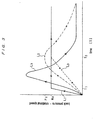
- such a time-dependent change is represented by a broken-line curve L 0 of a constant low gradient which reaches a steady rotational speed N 0 in a longer time T 0 than a time T 1 with the conventional pump.
- the vacuum pump 32 keeps the steady rotational speed N 0 .
- a change in the back pressure on the vacuum pump 32 is represented by a broken-line curve L 2 .
- the change in the back pressure represented by the broken-line curve L 2 has an initial peak value P 0 smaller than the peak value of the conventional back pressure whose change is represented by a curve L 3 when the rotational speed changes according to a solid-line curve L 1 .
- the gradient N 0 /T 0 of the rotational speed change curve L 0 is determined experimentally or calculated from past experimental data depending on the capability of the vacuum pump 32, the volume, of the vacuum chamber 10, and the conductance of the discharge pipe 34, so that the vacuum pump 32 can achieve a given evacuating capability insofar as the peak value P 0 does not pose an excessive load on the motor which actuates the vacuum pump 32.
- FIG. 5 shows another embodiment of the present invention.
- a booster pump 50 is disposed upstream of the vacuum pump (main pump) 32 in the discharge path.
- the pumps 32, 50 are actuated by respective motors 40, 46, each of which comprises a brushless DC motor having a rotational speed controller 42 which employs an inverter.
- the discharge pipe 34 has a small diameter, and the back pressure sensor 44 is disposed near the outlet port of the discharge pipe 34 for the control of the rotational speed of the main pump based on the output of the back pressure sensor 44.
- a target range for the back pressure is kept between a lower limit P 1 and an upper limit P 2 in order to discharge the gas stably and not to apply an excessive load to the motors 40, 46.
- step 1 When a discharge process is started, a large amount of gas is discharged, tending to increase the back pressure, as described above. Therefore, a command is applied to start only the main pump 32 at a minimum rotational speed (step 1).
- the back pressure rises up to an initial peak value that is determined depending on the volume and initial pressure of the vacuum chamber 10, which is to be evacuated, and the evacuating capability at the minimum rotational speed of the main pump 32 (step 2). Then, the back pressure begins to descend.
- the vacuum chamber 10 is evacuated at the minimum rotational speed of the main pump 32 until the back pressure descends to and below the lower limit P 1 (step 3).
- the rotational speed of the main pump 32 is increased at a constant pitch (steps 4, 4').
- the main pump 32 is kept at the rotational speed that has been reached (steps 5, 5'). In this manner, if the volume of the vacuum chamber 10 and the evacuating capability of the main pump 32 balance each other, the rotational speed of the main pump 32 is controlled to adjust the back pressure at around the lower limit P 1 , so that the evacuating apparatus can continuously operate stably.
- the volume of the vacuum chamber 10 and the evacuating capability of the main pump 32 are brought out of balance with each other.
- the main pump 32 fails to keep up with the command, or the back pressure fails to increase.
- a timer or the like is used to detect the back pressure that is continuously equal to or below the lower limit P 1 , and a command is given to start the booster pump 50 at a rated rotational speed (step 6). In this manner, if the evacuating load on the vacuum chamber 10 is relatively large in balance with the sum of the evacuating capabilities of the main pump 32 and the booster pump 50, then the evacuating apparatus can continuously operate stably (step 7).
- the booster pump 50 is shut down, and only the main pump 32 is operated (step 8). Therefore, the booster pump 50 is turned on or off depending on the back pressure.
- the booster pump 50 may be of the variable speed type and may be controlled in the same fashion as with the main pump 32 in the preceding embodiment to adjust the back pressure at around the lower limit P 1 .
- the booster pump 50 may be operated at the rated rotational speed, whereas the rotational speed of the main pump 32 may be controlled. If the main pump 32 has a lower minimum rated rotational speed, then the initial stage control process illustrated in FIG. 2 or 4 may be performed for the main pump 32.
- the main pump 32 and the booster pump 50 may be prevented from being simultaneously operated to avoid a meaningless continuous evacuating operation. Since the back pressure on the pump does not exceed a predetermined value, the temperature of the pump is prevented from unduly increasing due to an excessive increase in the back pressure, so that the pump can operate stably.
- a partial cooling system in the form of a conventional manifold cooler may be employed. Since no direct cooling system is employed, the temperature in the pump is not excessively lowered. Therefore, the evacuating apparatus is applicable to a process where reaction products are likely to occur.
- the back pressure on the vacuum pump is controlled so as not to exceed a certain value.
- the booster pump may be added which is started only when the evacuating load is increased in the process of operating the evacuating apparatus.
- the evacuating apparatus can operate stably while saving energy. Even though the diameter of the discharge pipe is small, the evacuating apparatus can operate stably without by avoiding overloaded operation.
- the discharge pipe whose diameter is smaller than required by the evacuating capability, it is possible to effectively utilize the space in an expensive clean room.
- the present invention is useful as an apparatus for and a method of evacuating a vacuum chamber (process chamber) or the like of a processing apparatus such as an etching apparatus, a chemical vapor deposition apparatus (CVD), or the like that is used in a semiconductor fabrication process.
- a processing apparatus such as an etching apparatus, a chemical vapor deposition apparatus (CVD), or the like that is used in a semiconductor fabrication process.
- CVD chemical vapor deposition apparatus
Landscapes
- Engineering & Computer Science (AREA)
- Mechanical Engineering (AREA)
- General Engineering & Computer Science (AREA)
- Compressors, Vaccum Pumps And Other Relevant Systems (AREA)
- Control Of Positive-Displacement Pumps (AREA)
- Non-Positive Displacement Air Blowers (AREA)
- Drying Of Semiconductors (AREA)
- Control Of Positive-Displacement Air Blowers (AREA)
Abstract
The present invention is related to an apparatus
for and a method of evacuating a vacuum chamber (process
chamber) or the like of a semiconductor fabrication
facility, for example. The evacuating apparatus has a
vacuum chamber (10) to be evacuated, a discharge pipe (34)
connecting the vacuum chamber to an atmospheric port, a
vacuum pump (32) connected to the discharge pipe (34) and
operable at a variable rotational speed, and a controller
(42) for controlling the rotational speed of the vacuum pump
(32).
Description
The present invention relates to an apparatus for
and a method of evacuating a vacuum chamber (process
chamber) of, for example, a semiconductor fabrication
facility or the like.
FIG. 7 of the accompanying drawings shows an
evacuating path for evacuating a vacuum chamber 10, which is
used in an etching apparatus, a chemical vapor deposition
apparatus (CVD), or the like for a semiconductor fabrication
process. To the vacuum chamber 10, there is connected an
inlet port 14a of a vacuum pump 14 of an evacuating system
12. The vacuum pump 14 has an outlet port 14b connected to
a discharge pipe 16. The vacuum pump 14 serves to increase
the pressure of a process gas discharged from the vacuum
chamber 10 to the atmospheric pressure. The vacuum pump 14
has conventionally been in the form of an oil rotary pump,
but primarily comprises a dry pump at present.
If the vacuum level required by the vacuum
chamber 10 is higher than the vacuum level that can be
acquired by the vacuum pump 14, then an ultrahigh vacuum
pump such as a turbo-molecular pump or the like may be
positioned upstream of the vacuum pump. If the process gas
is of a type that cannot be discharged directly into the
atmosphere, then a discharge gas processing facility is
connected to the discharge pipe 16.
Heretofore, it has generally been customary to
use an induction motor rotatable at a rated rotational speed
as a motor 20 of the vacuum pump 14 of the evacuating system
12. In order to allow a large amount of gas to evacuate
smoothly when the pump is started or when the atmosphere air
is introduced in the chamber, and also to keep the back
pressure on the vacuum pump 14 in an allowable range, the
discharge pipe 16 has had an inside diameter of about 40 mm
if the process gas is discharged at a rate of about 2000
L/min, for example.
Usually, the vacuum chamber of the semiconductor
fabrication facility is placed in a clean room, and hence
the discharge pipe is occasionally laid over a long distance
in the clean room up to the external space. If the
discharge pipe is large in diameter, then it will take up a
costly space and have its layout limited due to interference
with other component devices of the semiconductor
fabrication facility. If the discharge pipe is small in
diameter, then it causes an undue increase in the back
pressure on the vacuum pump at the time a large amount of
gas flows when the pump is started or the atmosphere air is
introduced, with the result that the vacuum pump tends to
fail to operate due to an excessive load. Therefore, there
is a certain limitation to make the reduce of the diameter
of the discharge pipe.
The present invention has been made in view of
the above drawbacks. It is an object of the present
invention to provide an apparatus for and a method of
evacuating a vacuum chamber with an evacuating system which
includes a discharge pipe having a reduced diameter for
space saving, and which operates stably by avoiding
overloaded operation.
According to an invention recited in claim 1, an
apparatus for evacuating a vacuum chamber comprises a vacuum
chamber to be evacuated, a discharge pipe connecting the
vacuum chamber to an atmospheric port, a vacuum pump
connected to the discharge pipe and operable at a variable
rotational speed, and a controller for controlling the
rotational speed of the vacuum pump. Even when a large
amount of gas is discharged at the time the vacuum pump is
started, the back pressure on the vacuum pump is controlled
so as not to exceed a certain value. Thus, the evacuating
apparatus can operate stably. The discharge pipe whose
diameter is smaller than required by the evacuating
capability can be used, and it is possible to effectively
utilize the space in an expensive clean room.
According to an invention recited in claim 2, the
apparatus according to claim 1 further comprises a back
pressure sensor connected to a discharge port of the vacuum
pump, for detecting a back pressure on the vacuum pump,
wherein the controller controls the rotational speed of the
vacuum pump based on a detected output from the back
pressure sensor. Therefore, the back pressure can be
controlled accurately at all times to operate the evacuating
apparatus stably.
According to an invention recited in claim 3, in
the apparatus according to claim 2, herein the controller
controls the rotational speed of the vacuum pump to keep the
detected output from the back pressure sensor in a
predetermined target range.
According to an invention recited in claim 4, in
the apparatus according to claim 2, the controller controls
the rotational speed of the vacuum pump to prevent the
detected output of the back pressure sensor from exceeding a
predetermined target value.
According to an invention recited in claim 5, the
apparatus according to claim 2 further comprises a booster
pump connected to the discharge pipe in series with the
vacuum pump, wherein the controller controls to start the
booster pump when the vacuum pump has an insufficient
evacuating capability, based on the detected output from the
back pressure sensor. Therefore, evacuating apparatus is
thus capable of handling a large evacuating load while
saving energy.
According to an invention recited in claim 6, in
the apparatus according to claim 1, the controller controls
the rotational speed of the vacuum pump according to a
previously inputted pattern of changes in the rotational
speed. The back pressure can thus be controlled with a
simple apparatus arrangement, and the evacuating apparatus
can start up stably.
According to an invention recited in claim 7, in
the apparatus according to claim 1, the discharge pipe has a
conductance smaller than the evacuating capability of the
vacuum pump. Therefore, the space required for piping is
reduced, and the space in an expensive clean room can be
effectively utilized. The pipe and the apparatus are easily
joined to each other.
According to an invention recited in claim 8,
there is provided a method of evacuating a vacuum chamber
through a discharge pipe with a vacuum pump having a
variable rotational speed, which comprises the steps of
detecting a back pressure on the vacuum pump, and
controlling the rotational speed of the vacuum pump based on
the detected back pressure on the vacuum pump.
According to an invention recited in claim 9, in
the method according to claim 8, a booster pump is connected
to the discharge pipe in series with the vacuum pump, and
the method further comprises the step of starting the
booster pump when the vacuum pump has an insufficient
evacuating capability, based on the detected back pressure
on the vacuum pump.
According to an invention recited in claim 10,
the method according to claim 8 further comprises the step
of controlling the rotational speed of the vacuum pump
according to a previously inputted pattern of changes in the
rotational speed in an initial period of evacuating the
vacuum pump.
According to an invention recited in claim 11,
there is provided a method of evacuating a vacuum chamber
through a discharge pipe with a vacuum pump having a
variable rotational speed, which comprises the step of
controlling the rotational speed of the vacuum pump
according to a previously inputted pattern of changes in the
rotational speed in an initial period of evacuating the
vacuum pump.
According to an invention recited in claim 12, in
the method according to claim 11, the rotational speed
increases at a rate selected to keep an initial peak of the
back pressure in evacuating the vacuum chamber, equal to or
below a predetermined value.
According to an invention recited in claim 13, in
the method according to claim 11, the rotational speed
increases stepwise.
Embodiments of the present invention will be
described below with reference to the drawings. FIG. 1
shows an evacuating system 30 for evacuating a vacuum
chamber 10, which is used in an etching apparatus, a
chemical vapor deposition apparatus (CVD), or the like for a
semiconductor fabrication process performed thereby. The
vacuum chamber 10 is connected to an inlet port 32a of a
vacuum pump 32, which has an outlet port 32b connected to a
discharge pipe 34.
The vacuum pump 32 comprises a so-called dry pump
which does not use a lubricant in a gas passage. The vacuum
pump 32 is operated by a motor 40 comprising a DC motor,
particularly, a brushless DC motor, having a rotational
speed controller 42 which employs an inverter (frequency
converting circuit), for example. The discharge pipe 34 has
a diameter smaller than the diameter of the conventional
discharge pipe 16 shown in FIG. 7. For example, if the gas
is discharged at a rate of about 2000 L(liter)/min., then
the discharge pipe 34 has an inside diameter of about 10 mm.
The inside diameter of the discharge pipe 34 is determined
such that the conductance is of a certain value, in view of
the length of the discharge pipe 34.
A back pressure sensor 44 for detecting the
pressure in the discharge pipe 34, i.e., the back pressure
on the vacuum pump 32, is disposed near the outlet port of
the discharge pipe 34. An output signal from the back
pressure sensor 44 is applied to the rotational speed
controller 42 of the motor 40.
A method of operating the vacuum pump 32 for
starting the vacuum pump 32 will be described below with
reference to FIG. 2. In this embodiment, the rotational
speed of the vacuum pump 32 is controlled to keep the back
pressure on the vacuum pump 32 at a predetermined value P0.
Specifically, when the detected back pressure of the vacuum
pump 32 reaches P0 + α, the rotational speed controller 42
lowers the rotational speed of the motor 40, and when the
detected back pressure of the vacuum pump 32 becomes lower
than P0 - α, the rotational speed controller 42 raises the
rotational speed of the motor 40. As a result, as indicated
by the broken-line curve in FIG. 2, the back pressure is
kept substantially at the predetermined value P0, allowing
the vacuum pump 32 to operate stably though a prolonged time
is required. After elapse of a predetermined time, the back
pressure drops below the predetermined value P0, and the
vacuum pump 32 enters a steady mode of operation.
In the above embodiment, the vacuum pump 32 is
controlled in a feedback loop using the back pressure sensor
44. Another embodiment which performs a simpler sequence
control mode will be described below with reference to FIG.
3. In this embodiment, the stationary installation of the
back pressure sensor 44 is not required. A time-dependent
change in the rotational speed of the vacuum pump 32 at the
time it is started is inputted in advance to the rotational
speed controller 42. In FIG. 3, such a time-dependent
change is represented by a broken-line curve L0 of a
constant low gradient which reaches a steady rotational
speed N0 in a longer time T0 than a time T1 with the
conventional pump. After the time T0, the vacuum pump 32
keeps the steady rotational speed N0.
In FIG. 3, a change in the back pressure on the
vacuum pump 32 is represented by a broken-line curve L2.
The change in the back pressure represented by the broken-line
curve L2 has an initial peak value P0 smaller than the
peak value of the conventional back pressure whose change is
represented by a curve L3 when the rotational speed changes
according to a solid-line curve L1. The gradient N0/T0 of
the rotational speed change curve L0 is determined
experimentally or calculated from past experimental data
depending on the capability of the vacuum pump 32, the
volume, of the vacuum chamber 10, and the conductance of the
discharge pipe 34, so that the vacuum pump 32 can achieve a
given evacuating capability insofar as the peak value P0
does not pose an excessive load on the motor which actuates
the vacuum pump 32.
In this embodiment, since a complex control
process such as the feedback control process based on the
back pressure sensor is not carried out, no back pressure
sensor is required, and the same advantages as those of the
preceding embodiment can be achieved with a simpler
arrangement. Gradient settings may be selected depending on
changes in conditions such as the capability of the vacuum
pump 32, the volume of the vacuum chamber 10, and the
conductance of the discharge pipe 34. In the embodiment
shown in FIG. 3, the rotational speed of the motor increases
linearly. However, the rotational speed of the motor may
increase stepwise as shown in FIG. 4.
FIG. 5 shows another embodiment of the present
invention. In the embodiment shown in FIG. 5, a booster
pump 50 is disposed upstream of the vacuum pump (main pump)
32 in the discharge path. The pumps 32, 50 are actuated by
respective motors 40, 46, each of which comprises a
brushless DC motor having a rotational speed controller 42
which employs an inverter. As with the previous embodiment,
the discharge pipe 34 has a small diameter, and the back
pressure sensor 44 is disposed near the outlet port of the
discharge pipe 34 for the control of the rotational speed of
the main pump based on the output of the back pressure
sensor 44.
A method of controlling the evacuating apparatus
according to the embodiment shown in FIG. 5 will be
described below with reference to FIG. 6. In this
embodiment, a target range for the back pressure is kept
between a lower limit P1 and an upper limit P2 in order to
discharge the gas stably and not to apply an excessive load
to the motors 40, 46.
When a discharge process is started, a large
amount of gas is discharged, tending to increase the back
pressure, as described above. Therefore, a command is
applied to start only the main pump 32 at a minimum
rotational speed (step 1). The back pressure rises up to an
initial peak value that is determined depending on the
volume and initial pressure of the vacuum chamber 10, which
is to be evacuated, and the evacuating capability at the
minimum rotational speed of the main pump 32 (step 2).
Then, the back pressure begins to descend. The vacuum
chamber 10 is evacuated at the minimum rotational speed of
the main pump 32 until the back pressure descends to and
below the lower limit P1 (step 3).
When the back pressure falls to and below the
lower limit P1, the rotational speed of the main pump 32 is
increased at a constant pitch (steps 4, 4'). When the back
pressure rises beyond the lower limit P1 and enters the
target range, the main pump 32 is kept at the rotational
speed that has been reached (steps 5, 5'). In this manner,
if the volume of the vacuum chamber 10 and the evacuating
capability of the main pump 32 balance each other, the
rotational speed of the main pump 32 is controlled to adjust
the back pressure at around the lower limit P1, so that the
evacuating apparatus can continuously operate stably.
When the amount of gas produced by the vacuum
chamber increases, the volume of the vacuum chamber 10 and
the evacuating capability of the main pump 32 are brought
out of balance with each other. At this time, even if a
command is applied to increase the rotational speed of the
main pump 32, the main pump 32 fails to keep up with the
command, or the back pressure fails to increase. In this
case, a timer or the like is used to detect the back
pressure that is continuously equal to or below the lower
limit P1, and a command is given to start the booster pump
50 at a rated rotational speed (step 6). In this manner, if
the evacuating load on the vacuum chamber 10 is relatively
large in balance with the sum of the evacuating capabilities
of the main pump 32 and the booster pump 50, then the
evacuating apparatus can continuously operate stably (step
7).
If the back pressure increases beyond the upper
limit P2 when the main pump 32 and the booster pump 50 are
operated at their rated rotational speeds, then the booster
pump 50 is shut down, and only the main pump 32 is operated
(step 8). Therefore, the booster pump 50 is turned on or
off depending on the back pressure.
In the above embodiment, the booster pump 50 may
be of the variable speed type and may be controlled in the
same fashion as with the main pump 32 in the preceding
embodiment to adjust the back pressure at around the lower
limit P1. Alternatively, the booster pump 50 may be
operated at the rated rotational speed, whereas the
rotational speed of the main pump 32 may be controlled. If
the main pump 32 has a lower minimum rated rotational speed,
then the initial stage control process illustrated in FIG. 2
or 4 may be performed for the main pump 32.
In this embodiment, if the piping system suffers
leakage for some reason, then the main pump 32 and the
booster pump 50 may be prevented from being simultaneously
operated to avoid a meaningless continuous evacuating
operation. Since the back pressure on the pump does not
exceed a predetermined value, the temperature of the pump is
prevented from unduly increasing due to an excessive
increase in the back pressure, so that the pump can operate
stably.
For the same reasons, it is not necessary to
provide a jacket for passing a cooling medium such as water
around the pump casing to directly cool the pump casing, but
a partial cooling system in the form of a conventional
manifold cooler may be employed. Since no direct cooling
system is employed, the temperature in the pump is not
excessively lowered. Therefore, the evacuating apparatus is
applicable to a process where reaction products are likely
to occur.
According to the present invention, as described
above, even when a large amount of gas is discharged at the
time the vacuum pump is started, the back pressure on the
vacuum pump is controlled so as not to exceed a certain
value. The booster pump may be added which is started only
when the evacuating load is increased in the process of
operating the evacuating apparatus. Thus, the evacuating
apparatus can operate stably while saving energy. Even
though the diameter of the discharge pipe is small, the
evacuating apparatus can operate stably without by avoiding
overloaded operation. By using the discharge pipe whose
diameter is smaller than required by the evacuating
capability, it is possible to effectively utilize the space
in an expensive clean room.
The present invention is useful as an apparatus
for and a method of evacuating a vacuum chamber (process
chamber) or the like of a processing apparatus such as an
etching apparatus, a chemical vapor deposition apparatus
(CVD), or the like that is used in a semiconductor
fabrication process.
Claims (13)
- An apparatus for evacuating a vacuum chamber, comprising:a vacuum chamber to be evacuated;a discharge pipe connecting said vacuum chamber to an atmospheric port;a vacuum pump connected to said discharge pipe and operable at a variable rotational speed; anda controller for controlling the rotational speed of said vacuum pump.
- An apparatus according to claim 1, further comprising:a back pressure sensor connected to a discharge port of said vacuum pump for detecting a back pressure on the vacuum pump, wherein said controller controls the rotational speed of said vacuum pump based on a detected output from said back pressure sensor.
- An apparatus according to claim 2, wherein said controller controls the rotational speed of said vacuum pump to keep the detected output from said back pressure sensor in a predetermined target range.
- An apparatus according to claim 2, wherein said controller controls the rotational speed of said vacuum pump to prevent the detected output of said back pressure sensor from exceeding a predetermined target value.
- An apparatus according to claim 2, further comprising:a booster pump connected to said discharge pipe in series with said vacuum pump, wherein said controller controls to start said booster pump when said vacuum pump has an insufficient evacuating capability, based on the detected output from said back pressure sensor.
- An apparatus according to claim 1, wherein said controller controls the rotational speed of said vacuum pump according to a previously inputted pattern of changes in the rotational speed.
- An apparatus according to claim 1, wherein said discharge pipe has a conductance smaller than the evacuating capability of said vacuum pump.
- A method of evacuating a vacuum chamber through a discharge pipe with a vacuum pump having a variable rotational speed, comprising:detecting a back pressure on said vacuum pump; andcontrolling the rotational speed of said vacuum pump based on the detected back pressure on said vacuum pump.
- A method according to claim 8, wherein a booster pump is connected to said discharge pipe in series with said vacuum pump, further comprising:starting said booster pump when said vacuum pump has an insufficient evacuating capability, based on the detected back pressure on said vacuum pump.
- A method according to claim 8, further comprising:controlling the rotational speed of said vacuum pump according to a previously inputted pattern of changes in the rotational speed in an initial period of evacuating the vacuum pump.
- A method of evacuating a vacuum chamber through a discharge pipe with a vacuum pump having a variable rotational speed, comprising:controlling the rotational speed of said vacuum pump according to a previously inputted pattern of changes in the rotational speed in an initial period of evacuating the vacuum chamber.
- A method according to claim 11, wherein the rotational speed increases at a rate selected to keep an initial peak of the back pressure in evacuating the vacuum chamber, equal to or below a predetermined value.
- A method according to claim 11, wherein the rotational speed increases stepwise.
Applications Claiming Priority (5)
| Application Number | Priority Date | Filing Date | Title |
|---|---|---|---|
| JP15538198 | 1998-05-20 | ||
| JP15538198 | 1998-05-20 | ||
| JP26171598A JP3929185B2 (en) | 1998-05-20 | 1998-09-16 | Vacuum exhaust apparatus and method |
| JP26171598 | 1998-09-16 | ||
| PCT/JP1999/002645 WO1999060272A1 (en) | 1998-05-20 | 1999-05-20 | Device and method for evacuation |
Publications (2)
| Publication Number | Publication Date |
|---|---|
| EP1081380A1 true EP1081380A1 (en) | 2001-03-07 |
| EP1081380A4 EP1081380A4 (en) | 2006-08-02 |
Family
ID=26483399
Family Applications (1)
| Application Number | Title | Priority Date | Filing Date |
|---|---|---|---|
| EP99921197A Withdrawn EP1081380A4 (en) | 1998-05-20 | 1999-05-20 | Device and method for evacuation |
Country Status (6)
| Country | Link |
|---|---|
| US (1) | US6474949B1 (en) |
| EP (1) | EP1081380A4 (en) |
| JP (1) | JP3929185B2 (en) |
| KR (1) | KR100576761B1 (en) |
| TW (1) | TW483988B (en) |
| WO (1) | WO1999060272A1 (en) |
Cited By (8)
| Publication number | Priority date | Publication date | Assignee | Title |
|---|---|---|---|---|
| EP1344941A1 (en) * | 2002-03-13 | 2003-09-17 | BOC Edwards Technologies, Limited | RPM control for a vacuum pump system |
| WO2003100259A1 (en) * | 2002-05-22 | 2003-12-04 | Applied Materials, Inc. | Variable speed vacuum pump control method and apparatus |
| WO2004018879A1 (en) * | 2002-08-20 | 2004-03-04 | Ebara Corporation | Vacuum pump and method of starting the same |
| US6739840B2 (en) | 2002-05-22 | 2004-05-25 | Applied Materials Inc | Speed control of variable speed pump |
| WO2004055378A1 (en) * | 2002-12-17 | 2004-07-01 | The Boc Group Plc | Vacuum pumping arrangement and method of operating same |
| WO2006059027A1 (en) * | 2004-12-03 | 2006-06-08 | Alcatel Lucent | Gas partial pressure control for process optimization |
| DE102005017418A1 (en) * | 2005-04-15 | 2006-10-19 | Leybold Vacuum Gmbh | Turbo molecular pump has integrated pressure sensor, at pre-vacuum zone, to give actual pressure conditions at outflow from turbo rotor |
| CN102220994A (en) * | 2011-06-20 | 2011-10-19 | 昆山振昆纳米科技有限公司 | Angle valve of vacuum chamber |
Families Citing this family (41)
| Publication number | Priority date | Publication date | Assignee | Title |
|---|---|---|---|---|
| US8172546B2 (en) | 1998-11-23 | 2012-05-08 | Entegris, Inc. | System and method for correcting for pressure variations using a motor |
| KR100565032B1 (en) * | 2001-03-29 | 2006-03-30 | 가부시키가이샤 도요다 쥬오 겐큐쇼 | Manufacturing apparatus and manufacturing method of silicon structure |
| US7083392B2 (en) * | 2001-11-26 | 2006-08-01 | Shurflo Pump Manufacturing Company, Inc. | Pump and pump control circuit apparatus and method |
| US8337166B2 (en) | 2001-11-26 | 2012-12-25 | Shurflo, Llc | Pump and pump control circuit apparatus and method |
| US7153362B2 (en) * | 2002-04-30 | 2006-12-26 | Samsung Electronics Co., Ltd. | System and method for real time deposition process control based on resulting product detection |
| KR20030011024A (en) * | 2002-10-23 | 2003-02-06 | 린영태 | A constant pressure variable speed inverter control booster pump system |
| GB0229353D0 (en) * | 2002-12-17 | 2003-01-22 | Boc Group Plc | Vacuum pumping system and method of operating a vacuum pumping arrangement |
| FR2854667B1 (en) * | 2003-05-09 | 2006-07-28 | Cit Alcatel | PRESSURE CONTROL IN THE CHAMBER OF PROCESSES BY VARIATION OF PUMPS SPEED, CONTROL VALVE AND INJECTION OF NEUTRAL GAS |
| JP4218756B2 (en) * | 2003-10-17 | 2009-02-04 | 株式会社荏原製作所 | Vacuum exhaust device |
| US8540493B2 (en) | 2003-12-08 | 2013-09-24 | Sta-Rite Industries, Llc | Pump control system and method |
| GB0401396D0 (en) * | 2004-01-22 | 2004-02-25 | Boc Group Plc | Pressure control method |
| US7854597B2 (en) | 2004-08-26 | 2010-12-21 | Pentair Water Pool And Spa, Inc. | Pumping system with two way communication |
| US7874808B2 (en) * | 2004-08-26 | 2011-01-25 | Pentair Water Pool And Spa, Inc. | Variable speed pumping system and method |
| US8602745B2 (en) | 2004-08-26 | 2013-12-10 | Pentair Water Pool And Spa, Inc. | Anti-entrapment and anti-dead head function |
| US8480373B2 (en) | 2004-08-26 | 2013-07-09 | Pentair Water Pool And Spa, Inc. | Filter loading |
| US7845913B2 (en) | 2004-08-26 | 2010-12-07 | Pentair Water Pool And Spa, Inc. | Flow control |
| US8019479B2 (en) * | 2004-08-26 | 2011-09-13 | Pentair Water Pool And Spa, Inc. | Control algorithm of variable speed pumping system |
| US7686589B2 (en) | 2004-08-26 | 2010-03-30 | Pentair Water Pool And Spa, Inc. | Pumping system with power optimization |
| US8469675B2 (en) | 2004-08-26 | 2013-06-25 | Pentair Water Pool And Spa, Inc. | Priming protection |
| DE102004048866A1 (en) * | 2004-10-07 | 2006-04-13 | Leybold Vacuum Gmbh | Fast-rotating vacuum pump |
| GB0424198D0 (en) * | 2004-11-01 | 2004-12-01 | Boc Group Plc | Pumping arrangement |
| EP1859169A2 (en) | 2004-11-23 | 2007-11-28 | Entegris, Inc. | System and method for a variable home position dispense system |
| CN100507269C (en) * | 2005-11-02 | 2009-07-01 | 旺宏电子股份有限公司 | Vacuum air extractor |
| US8753097B2 (en) | 2005-11-21 | 2014-06-17 | Entegris, Inc. | Method and system for high viscosity pump |
| EP1952022B1 (en) | 2005-11-21 | 2014-11-12 | Entegris, Inc. | System and method for a pump with reduced form factor |
| US8083498B2 (en) | 2005-12-02 | 2011-12-27 | Entegris, Inc. | System and method for position control of a mechanical piston in a pump |
| US7878765B2 (en) | 2005-12-02 | 2011-02-01 | Entegris, Inc. | System and method for monitoring operation of a pump |
| US8029247B2 (en) | 2005-12-02 | 2011-10-04 | Entegris, Inc. | System and method for pressure compensation in a pump |
| TWI402423B (en) | 2006-02-28 | 2013-07-21 | Entegris Inc | System and method for operation of a pump |
| JP5323699B2 (en) * | 2006-07-31 | 2013-10-23 | アプライド マテリアルズ インコーポレイテッド | Method and apparatus for on-site analysis of gases in electronic device manufacturing systems |
| JP5322254B2 (en) * | 2007-06-29 | 2013-10-23 | 東京エレクトロン株式会社 | Vacuum processing apparatus, vacuum processing method, and storage medium |
| WO2010042406A1 (en) | 2008-10-06 | 2010-04-15 | Pentair Water Pool And Spa, Inc. | Method of operating a safety vacuum release system |
| US9556874B2 (en) | 2009-06-09 | 2017-01-31 | Pentair Flow Technologies, Llc | Method of controlling a pump and motor |
| US8564233B2 (en) | 2009-06-09 | 2013-10-22 | Sta-Rite Industries, Llc | Safety system and method for pump and motor |
| US8436559B2 (en) | 2009-06-09 | 2013-05-07 | Sta-Rite Industries, Llc | System and method for motor drive control pad and drive terminals |
| BR112013014476A2 (en) | 2010-12-08 | 2016-09-20 | Pentair Water Pool & Spa Inc | vacuum relief relief valve for a vacuum release safety system |
| GB2492065A (en) * | 2011-06-16 | 2012-12-26 | Edwards Ltd | Noise reduction of a vacuum pumping system |
| US10465676B2 (en) | 2011-11-01 | 2019-11-05 | Pentair Water Pool And Spa, Inc. | Flow locking system and method |
| US9885360B2 (en) | 2012-10-25 | 2018-02-06 | Pentair Flow Technologies, Llc | Battery backup sump pump systems and methods |
| GB2508396B (en) * | 2012-11-30 | 2015-10-07 | Edwards Ltd | Improvements in and relating to vacuum conduits |
| US20150098839A1 (en) * | 2013-10-08 | 2015-04-09 | Ingersoll-Rand Company | Pump Systems and Methods |
Family Cites Families (15)
| Publication number | Priority date | Publication date | Assignee | Title |
|---|---|---|---|---|
| JPS62243982A (en) * | 1986-04-14 | 1987-10-24 | Hitachi Ltd | 2-stage vacuum pump and operating method thereof |
| FR2621141B1 (en) * | 1987-09-25 | 1989-12-01 | Cit Alcatel | METHOD FOR STARTING SERIES COUPLED VACUUM PUMPS, AND DEVICE FOR CARRYING OUT SAID METHOD |
| US4850806A (en) * | 1988-05-24 | 1989-07-25 | The Boc Group, Inc. | Controlled by-pass for a booster pump |
| JP2907898B2 (en) * | 1989-11-08 | 1999-06-21 | 株式会社日立製作所 | Air conditioner |
| JP3152350B2 (en) | 1990-05-31 | 2001-04-03 | 株式会社トーキン | Manufacturing method of small choke coil |
| JPH05195984A (en) * | 1992-01-22 | 1993-08-06 | Nec Yamagata Ltd | Turbo-vacuum pump |
| US5224836A (en) * | 1992-05-12 | 1993-07-06 | Ingersoll-Rand Company | Control system for prime driver of compressor and method |
| JP3278491B2 (en) * | 1993-04-19 | 2002-04-30 | 株式会社東芝 | Refrigeration cycle control device |
| JP3111790B2 (en) * | 1994-02-03 | 2000-11-27 | 株式会社日立製作所 | Flow control pump |
| JP3847357B2 (en) * | 1994-06-28 | 2006-11-22 | 株式会社荏原製作所 | Vacuum exhaust system |
| JP3699159B2 (en) * | 1995-05-24 | 2005-09-28 | 日本原子力研究所 | Vacuum pumping system for fusion equipment |
| US5641270A (en) * | 1995-07-31 | 1997-06-24 | Waters Investments Limited | Durable high-precision magnetostrictive pump |
| US5725358A (en) * | 1995-08-30 | 1998-03-10 | Binks Manufacturing Company | Pressure regulated electric pump |
| JPH09221381A (en) | 1996-02-08 | 1997-08-26 | Komatsu Electron Metals Co Ltd | Evacuating device for device for pulling up single crystal |
| JP3550879B2 (en) * | 1996-05-30 | 2004-08-04 | ダイキン工業株式会社 | Vacuum exhaust device |
-
1998
- 1998-09-16 JP JP26171598A patent/JP3929185B2/en not_active Expired - Fee Related
-
1999
- 1999-05-20 TW TW088108233A patent/TW483988B/en not_active IP Right Cessation
- 1999-05-20 KR KR1020007012893A patent/KR100576761B1/en not_active Expired - Fee Related
- 1999-05-20 WO PCT/JP1999/002645 patent/WO1999060272A1/en not_active Ceased
- 1999-05-20 EP EP99921197A patent/EP1081380A4/en not_active Withdrawn
- 1999-05-20 US US09/700,748 patent/US6474949B1/en not_active Expired - Fee Related
Cited By (12)
| Publication number | Priority date | Publication date | Assignee | Title |
|---|---|---|---|---|
| EP1344941A1 (en) * | 2002-03-13 | 2003-09-17 | BOC Edwards Technologies, Limited | RPM control for a vacuum pump system |
| WO2003100259A1 (en) * | 2002-05-22 | 2003-12-04 | Applied Materials, Inc. | Variable speed vacuum pump control method and apparatus |
| US6739840B2 (en) | 2002-05-22 | 2004-05-25 | Applied Materials Inc | Speed control of variable speed pump |
| US6966967B2 (en) | 2002-05-22 | 2005-11-22 | Applied Materials, Inc. | Variable speed pump control |
| WO2004018879A1 (en) * | 2002-08-20 | 2004-03-04 | Ebara Corporation | Vacuum pump and method of starting the same |
| WO2004055378A1 (en) * | 2002-12-17 | 2004-07-01 | The Boc Group Plc | Vacuum pumping arrangement and method of operating same |
| WO2006059027A1 (en) * | 2004-12-03 | 2006-06-08 | Alcatel Lucent | Gas partial pressure control for process optimization |
| FR2878913A1 (en) * | 2004-12-03 | 2006-06-09 | Cit Alcatel | CONTROL OF PARTIAL GAS PRESSURES FOR PROCESS OPTIMIZATION |
| EP1669609A1 (en) * | 2004-12-03 | 2006-06-14 | Alcatel | Gas partial pressure control for process optimisation |
| US7793685B2 (en) | 2004-12-03 | 2010-09-14 | Alcatel | Controlling gas partial pressures for process optimization |
| DE102005017418A1 (en) * | 2005-04-15 | 2006-10-19 | Leybold Vacuum Gmbh | Turbo molecular pump has integrated pressure sensor, at pre-vacuum zone, to give actual pressure conditions at outflow from turbo rotor |
| CN102220994A (en) * | 2011-06-20 | 2011-10-19 | 昆山振昆纳米科技有限公司 | Angle valve of vacuum chamber |
Also Published As
| Publication number | Publication date |
|---|---|
| WO1999060272A1 (en) | 1999-11-25 |
| TW483988B (en) | 2002-04-21 |
| JP2000038999A (en) | 2000-02-08 |
| US6474949B1 (en) | 2002-11-05 |
| JP3929185B2 (en) | 2007-06-13 |
| EP1081380A4 (en) | 2006-08-02 |
| KR20010025035A (en) | 2001-03-26 |
| KR100576761B1 (en) | 2006-05-03 |
Similar Documents
| Publication | Publication Date | Title |
|---|---|---|
| US6474949B1 (en) | Evacuating unit with reduced diameter exhaust duct | |
| RU2421632C2 (en) | Method of pump system operation | |
| US7077159B1 (en) | Processing apparatus having integrated pumping system | |
| JP5769722B2 (en) | Low power consumption exhaust method and apparatus | |
| US6896764B2 (en) | Vacuum processing apparatus and control method thereof | |
| US7245097B2 (en) | Motor control system and vacuum pump equipped with the motor control system | |
| EP1344941B1 (en) | RPM control for a vacuum pump system | |
| US6251192B1 (en) | Vacuum exhaust system | |
| US20070048145A1 (en) | Vacuum evacuation device and method, and substrate processing apparatus and method | |
| EP0900940B1 (en) | Method of operating a vacuum pump | |
| US9423790B2 (en) | Apparatus and method for self-tuning a processing system | |
| US6454524B1 (en) | Vacuum pump and vacuum apparatus | |
| US6711956B2 (en) | Method and apparatus for regulating exhaust pressure in evacuation system of semiconductor process chamber | |
| JP3930297B2 (en) | Turbo molecular pump | |
| JP3941147B2 (en) | Vacuum exhaust apparatus and maintenance method thereof | |
| WO2023228863A1 (en) | Vacuum pump and vacuum evacuation system | |
| CN116770275A (en) | Air extraction control method, device, medium and equipment of chemical vapor deposition equipment | |
| JP2003229417A (en) | Vacuum processing apparatus and method of controlling the same | |
| JP2019081944A (en) | Control method of vacuum valve | |
| KR20020080923A (en) | ventilation system of semiconductor device manufacturing equipment | |
| KR20230124900A (en) | vacuum pump and control unit | |
| US20030202874A1 (en) | Methods and apparatus for controlling power in vapor jet vacuum pumps | |
| JPH1183344A (en) | Condenser automatic vacuum controller | |
| JPH10112400A (en) | Plasma treating method | |
| JPH11257278A (en) | System for ensuring pressure regulation in the enclosure sucked by the vacuum pump |
Legal Events
| Date | Code | Title | Description |
|---|---|---|---|
| PUAI | Public reference made under article 153(3) epc to a published international application that has entered the european phase |
Free format text: ORIGINAL CODE: 0009012 |
|
| 17P | Request for examination filed |
Effective date: 20001114 |
|
| AK | Designated contracting states |
Kind code of ref document: A1 Designated state(s): DE FR GB IT |
|
| A4 | Supplementary search report drawn up and despatched |
Effective date: 20060705 |
|
| 17Q | First examination report despatched |
Effective date: 20070914 |
|
| STAA | Information on the status of an ep patent application or granted ep patent |
Free format text: STATUS: THE APPLICATION IS DEEMED TO BE WITHDRAWN |
|
| 18D | Application deemed to be withdrawn |
Effective date: 20110329 |