EP1081241B1 - Verfahren und Verwendung einer Vorrichtung zum Aufschäumen eines metallischen Werkstoffs - Google Patents
Verfahren und Verwendung einer Vorrichtung zum Aufschäumen eines metallischen Werkstoffs Download PDFInfo
- Publication number
- EP1081241B1 EP1081241B1 EP00114493A EP00114493A EP1081241B1 EP 1081241 B1 EP1081241 B1 EP 1081241B1 EP 00114493 A EP00114493 A EP 00114493A EP 00114493 A EP00114493 A EP 00114493A EP 1081241 B1 EP1081241 B1 EP 1081241B1
- Authority
- EP
- European Patent Office
- Prior art keywords
- foaming
- pressed part
- walls
- foamed
- mould
- Prior art date
- Legal status (The legal status is an assumption and is not a legal conclusion. Google has not performed a legal analysis and makes no representation as to the accuracy of the status listed.)
- Expired - Lifetime
Links
- 238000005187 foaming Methods 0.000 title claims abstract description 74
- 238000000034 method Methods 0.000 title claims description 26
- 239000000843 powder Substances 0.000 claims abstract description 19
- 229910052751 metal Inorganic materials 0.000 claims abstract description 15
- 239000002184 metal Substances 0.000 claims abstract description 15
- 239000003380 propellant Substances 0.000 claims abstract description 11
- 239000000203 mixture Substances 0.000 claims abstract description 10
- 238000010438 heat treatment Methods 0.000 claims abstract description 9
- 238000007493 shaping process Methods 0.000 claims 2
- 239000006260 foam Substances 0.000 abstract description 10
- 238000000465 moulding Methods 0.000 abstract description 8
- 239000000463 material Substances 0.000 abstract description 7
- 239000011265 semifinished product Substances 0.000 description 13
- XAGFODPZIPBFFR-UHFFFAOYSA-N aluminium Chemical compound [Al] XAGFODPZIPBFFR-UHFFFAOYSA-N 0.000 description 4
- 238000010586 diagram Methods 0.000 description 4
- 239000004033 plastic Substances 0.000 description 4
- 229920003023 plastic Polymers 0.000 description 4
- 239000008188 pellet Substances 0.000 description 3
- 239000011148 porous material Substances 0.000 description 3
- VTYYLEPIZMXCLO-UHFFFAOYSA-L Calcium carbonate Chemical compound [Ca+2].[O-]C([O-])=O VTYYLEPIZMXCLO-UHFFFAOYSA-L 0.000 description 2
- CDBYLPFSWZWCQE-UHFFFAOYSA-L Sodium Carbonate Chemical compound [Na+].[Na+].[O-]C([O-])=O CDBYLPFSWZWCQE-UHFFFAOYSA-L 0.000 description 2
- UIIMBOGNXHQVGW-UHFFFAOYSA-M Sodium bicarbonate Chemical compound [Na+].OC([O-])=O UIIMBOGNXHQVGW-UHFFFAOYSA-M 0.000 description 2
- 229910052782 aluminium Inorganic materials 0.000 description 2
- 239000002131 composite material Substances 0.000 description 2
- 238000009826 distribution Methods 0.000 description 2
- 239000012530 fluid Substances 0.000 description 2
- 239000006262 metallic foam Substances 0.000 description 2
- BWHMMNNQKKPAPP-UHFFFAOYSA-L potassium carbonate Chemical compound [K+].[K+].[O-]C([O-])=O BWHMMNNQKKPAPP-UHFFFAOYSA-L 0.000 description 2
- 239000000126 substance Substances 0.000 description 2
- 239000004604 Blowing Agent Substances 0.000 description 1
- 229910000831 Steel Inorganic materials 0.000 description 1
- 239000000956 alloy Substances 0.000 description 1
- 229910045601 alloy Inorganic materials 0.000 description 1
- 229940037003 alum Drugs 0.000 description 1
- WNROFYMDJYEPJX-UHFFFAOYSA-K aluminium hydroxide Chemical compound [OH-].[OH-].[OH-].[Al+3] WNROFYMDJYEPJX-UHFFFAOYSA-K 0.000 description 1
- 230000015572 biosynthetic process Effects 0.000 description 1
- 229910000019 calcium carbonate Inorganic materials 0.000 description 1
- 235000010216 calcium carbonate Nutrition 0.000 description 1
- 150000004649 carbonic acid derivatives Chemical class 0.000 description 1
- 239000000969 carrier Substances 0.000 description 1
- 238000009694 cold isostatic pressing Methods 0.000 description 1
- 238000010276 construction Methods 0.000 description 1
- 238000001816 cooling Methods 0.000 description 1
- 229910052802 copper Inorganic materials 0.000 description 1
- 238000000354 decomposition reaction Methods 0.000 description 1
- 238000005265 energy consumption Methods 0.000 description 1
- 239000006261 foam material Substances 0.000 description 1
- 150000004677 hydrates Chemical class 0.000 description 1
- 230000001939 inductive effect Effects 0.000 description 1
- 238000004519 manufacturing process Methods 0.000 description 1
- 239000000155 melt Substances 0.000 description 1
- 150000002731 mercury compounds Chemical class 0.000 description 1
- 229910052987 metal hydride Inorganic materials 0.000 description 1
- 150000004681 metal hydrides Chemical class 0.000 description 1
- 150000002739 metals Chemical class 0.000 description 1
- 238000005457 optimization Methods 0.000 description 1
- 229910000027 potassium carbonate Inorganic materials 0.000 description 1
- 235000011181 potassium carbonates Nutrition 0.000 description 1
- 238000003825 pressing Methods 0.000 description 1
- 239000011863 silicon-based powder Substances 0.000 description 1
- 229910000030 sodium bicarbonate Inorganic materials 0.000 description 1
- 235000017557 sodium bicarbonate Nutrition 0.000 description 1
- 229910000029 sodium carbonate Inorganic materials 0.000 description 1
- 235000017550 sodium carbonate Nutrition 0.000 description 1
- 235000011121 sodium hydroxide Nutrition 0.000 description 1
- 239000002689 soil Substances 0.000 description 1
- 239000007787 solid Substances 0.000 description 1
- 239000010959 steel Substances 0.000 description 1
- -1 titanium hydride Chemical compound 0.000 description 1
- 229910000048 titanium hydride Inorganic materials 0.000 description 1
Images

Classifications
-
- B—PERFORMING OPERATIONS; TRANSPORTING
- B22—CASTING; POWDER METALLURGY
- B22F—WORKING METALLIC POWDER; MANUFACTURE OF ARTICLES FROM METALLIC POWDER; MAKING METALLIC POWDER; APPARATUS OR DEVICES SPECIALLY ADAPTED FOR METALLIC POWDER
- B22F3/00—Manufacture of workpieces or articles from metallic powder characterised by the manner of compacting or sintering; Apparatus specially adapted therefor ; Presses and furnaces
- B22F3/10—Sintering only
- B22F3/11—Making porous workpieces or articles
- B22F3/1121—Making porous workpieces or articles by using decomposable, meltable or sublimatable fillers
- B22F3/1125—Making porous workpieces or articles by using decomposable, meltable or sublimatable fillers involving a foaming process
Definitions
- the invention relates to a method for foaming one of a mixture made of metal powder and a gas-releasing propellant powder compact (Semi-finished), wherein the compact between opposite walls of a foaming mold is arranged, whose geometries endkontur faced sides of the foamed Correspond to compacts, and then required for foaming Heat is applied to a heater.
- the invention relates to the use of a device for foaming a compact.
- a corresponding method can be found in DE 196 12 781 C1.
- a semi-finished product is made by compacting and solidifying a mixture of metal powder and blowing agents. Subsequently, the semifinished product is at least on one side with provided a solid metal sheet, to then be converted in the composite. This involves deep drawing and one-sided forming processes such as the fluid cell process in question. By these measures, the semifinished product can have a three-dimensional shape experienced curved surface areas.
- the semi-finished product is placed in a foaming mold, of which one wall is one side of the Semifinished product substantially comprehensively supports, so already their final contour having.
- the opposite wall the geometry of have desired final shape of the foamed semifinished product.
- the walls themselves are arranged at a fixed distance from each other, in order in this way the extent of expansion of the compact to be able to limit.
- the AufMumformen with the compact are z. B. introduced in a chamber furnace and heated to the desired temperature such that the metal by decomposition of the Propellant developed a foamy consistency, without any existing Top layer melts. After foaming, the body is then preferably in air cooled.
- Corresponding foam materials have a high rigidity with low mass that an insert z. B. in the bearing area of Kamsserien of vehicles or to fairing and Shielding purposes are used.
- From DE 197 44 300 A1 is a method for producing a metallic foam material can be seen, with a compact outside a form inductive to shortly before Warmed at the beginning of the foaming and then introduced into a mold, in which the Foaming takes place.
- the internal geometry of the mold gives the final shape of the foam body in front.
- the present invention is based on the problem of a method of the aforementioned type so that a rationalization of the foaming while increasing the quality and reproducibility of the body produced is possible. Also, the required energy consumption for foaming is reduced become.
- the problem is essentially solved in that the walls of the AufMumform adjustable to each other are arranged so that they during the Foaming at least partially flat on facing sides of the compact rest, and that the heat required for foaming over the walls as the Heating device is transmitted.
- the walls have a geometry, which correspond to the adjacent sides of the compact.
- the Pressling on at least one topcoat so that these on a wall during the Foaming can rest.
- the compacts in workpiece carriers bring, in turn, lie flat against a wall of the AufMumform, wherein the compact with one side surface or largely flat with the workpiece carrier or whose soil is in contact. The opposite side is then in contact with the another wall of the foaming mold.
- the distance after completion of the foaming for Setting a desired thickness of the foamed compact is adjusted. It can Consequently, by controlled adjustment of the walls of the AufMumform calibrating the Final geometry can be achieved.
- the distance of the walls during foaming fits automatically or by specific regulation on the progress of the foaming compact, optionally the expansion volume present in the expansion in critical states can be held.
- the arrangement may be a die for receiving the semifinished product and in this adjustable stamp include the semifinished product side optionally may have recesses into which the foaming Pressling expands, so that the foam body has a final geometry of the Course of the semifinished deviates.
- parameters can be controlled in the process and be influenced defined. Also, in the calibration step, different component heights may increase be made specifically, so that so-called tailored blanks desired geometry can be selectively produced.
- the invention relates to the use of a device comprising a a mold receiving and acted upon by heat AufMumform of the opposite walls have a geometry of final contoured sides of a have to be produced from the molding molded body, the walls boundaries of adjustable heatable punches than the heating device are at least partially in the flat contact with the compact and / or the at least one cover layer of the Pressings are used for frothing the mixture of metal powder and a a gas releasing propellant powder existing compact.
- Foaming foamed plastics is provided according to DE-A-37 24 316, plastic components in a limited by an adjustable arranged stamp cavity to produce a foam plastic body.
- the stamp as well a stationary wall have a heatable with high frequency voltage electrode on.
- the device at least three includes slidable stamp along common columns, wherein an inner punch Limitations of two foamable compacts is.
- propellant powder are customary propellants in question such as metal hydrides such.
- metal hydrides such as titanium hydride or carbonates such.
- Calcium carbonate, Potassium carbonate, sodium carbonate, sodium bicarbonate or hydrates such as.
- B. Aluminiumulfathydrat, alum, aluminum hydroxide or volatile substances such.
- B. Mercury compounds or powdered organic substances are customary propellants in question such as metal hydrides such.
- metal powder in particular aluminum powder, aluminum powder with Si and / or Cu, Si powder or any atomized aluminum base alloys can be used. hereby However, a limitation of the invention is not.
- the mixture is then z. B. desired by cold isostatic pressing to billets Pressed geometry.
- the semifinished product in particular as an open-pore compact getting produced.
- it can be on one side of the compact, especially on opposite sides Pages of the compact to be applied a topcoat.
- the z. B. are also part of the mixture. facings made of aluminum or steel are also possible.
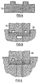
- a semifinished product produced in this way is purely in principle in FIGS. 1 and 2 with the reference numbers 10 provided.
- the compact 10 thus consists of the foamable, from the metal powder and the gas-releasing propellant powder core 12 and in the embodiment from opposite sides of the core 12 covering layers 14, 16 from Metal.
- the compact 10 is then between dies 18, 20 of a foaming mold arranged.
- the surfaces facing the pellet 10 of the punches 18, 20 have a Geometry, which correspond to the facing sides of the compact 10.
- the punches 18, 20 themselves are heatable, in order to transfer the required heat to the compact 10, so that the core 12 is foamed.
- the temperature is adjusted so that the cover layers 14, 16 do not melt.
- the stamp 18, 20 are mutually adjustable. This is indicated by arrows 22, 24.
- the lower punch 18 is stationary and the upper punch 20 to this arranged adjustable.
- the upper punch 20 along columns not shown adjustable.
- Kerns 12 causes the punch 20 is liftable in the direction of arrow 22, in Depending on the degree of progress of the foaming of the core 10. This is ensures that the compact 10 and its cover layers 14, 16 always flat with the Stamping 18, 20 comes into contact, whereby an optimal energy transfer takes place.
- the upper punch 20 can move in the direction of the lower Stamp 18 can be selectively adjusted to a cooled foamed compact desired thickness to provide. This calibration step ensures that that the foamed solidified compacts have the desired final geometry.
- FIG. 1 can be seen stamp 18, 20, facing each other Areas which are in surface contact with the compact 10, d. H. its cover layers 14, 16 are located, are flat. However, the corresponding areas can already have a geometry of a compact desired z. B. by deep drawing or by one-sided forming process such as fluid cell method obtained spatial geometry correspond.
- Fig. 2 is another embodiment of a device for foaming of compacts 10 is shown.
- the device 26 comprises a total of three punches 28, 30, 32, via which transfer the required heat to the pellets 10 to the foaming becomes.
- the punches 28, 30, 32 are adjustable along common columns 34, 36, wherein the actual foaming a targeted adjustment is done such that each of the foamed pellets 10 has a desired final thickness.
- Heat is applied via the middle punch 30 to both the top and the bottom transferred lower compact 10. This results in an energy optimization.
- FIGS. 3 and 5 are further embodiments of devices for foaming to take a compact 38, which has a cuboid shape as a starting shape, wherein the compact 38 may be a section of a strip-shaped semifinished product.
- a device 40th with a formed as a die lower punch 42 and one to this along the arrow 44 movable punch 46 is used, which in turn has recesses 48, 50.
- the surface along the bottom surface 52 of the die extends.
- the stamp 46 is located at the beginning of the foaming, So before heat on the die 42 and the punch 46 in the compact 38th is introduced on the facing surface of the compact 38 except the areas on, which are formed by the recess 48, 50. Then in the required Scope supplied heat to perform the foaming process. This expands foamable material during simultaneous lifting of the punch 44 in the recess 48, 50 in, so that a foamed body 54 results in a final geometry, such as this is shown in FIG. 4.
- the formation of the die 42 and the punch 46 can specifically a volume component made of metal foam, wherein in the manner described above, a calibration can be done.
- the Semi-finished products do not have the final geometry in reduced dimensions, which is the foamed Body should own.
- the compact 38 is in between a punch 54 and a Gesenk 56 formed space, wherein both the punch 54 and the die 56 in the semi-finished 38 facing surfaces recesses 58, 60, 62, through a desired final volume geometry of the foamed body can be achieved.
- FIG. 6 is a development of the devices according to FIGS. 3 and 5 in this respect as that in a die 64 a sliding element such as punch or slider 66th is arranged, which are mutually adjustable. Consequently, the device comprises a multi-part Die, whereby the shape of the foaming compact 38 an additional desired volume geometry can learn.
- a punch 68 adjustable To the die 64 is in the usual Way a punch 68 adjustable, the -wie in the embodiments of FIGS. 3 and 5 a Recess 70 may have, in which the foaming of the compact 38 at its Heating can expand.
- the procedure itself is on the comments refer to the previously reproduced examples.
Landscapes
- Engineering & Computer Science (AREA)
- Manufacturing & Machinery (AREA)
- Mechanical Engineering (AREA)
- Powder Metallurgy (AREA)
- Manufacture Of Porous Articles, And Recovery And Treatment Of Waste Products (AREA)
- Molds, Cores, And Manufacturing Methods Thereof (AREA)
Description
- Fig. 1
- eine Prinzipdarstellung einer ersten Ausführungsform einer Vorrichtung zum Aufschäumen eines Metallkörpers,
- Fig. 2
- eine Prinzipdarstellung einer zweiten Ausführungsform,
- Fig. 3
- eine Prinzipdarstellung einer dritten Ausführungsform,
- Fig. 4
- einen aufgeschäumten Körper,
- Fig. 5
- eine Prinzipdarstellung einer vierten Ausführungsform und
- Fig. 6
- eine Prinzipdarstellung einer fünften Ausführungsform.
Claims (15)
- Verfahren zum Aufschäumen eines aus einer Mischung aus Metallpulver und einem gasabspaltenden Treibmittelpulver bestehenden Presslings, wobei der Pressling zwischen gegenüberliegenden Wandungen einer Aufschäumform angeordnet wird, deren Geometrien endkonturierten Seiten des aufgeschäumten Presslings entsprechen, und sodann mit zum Aufschäumen erforderlicher Wärme einer Heizeinrichtung beaufschlagt wird,
dadurch gekennzeichnet, dass die Wandungen der Aufschäumform verstellbar zueinander derart angeordnet werden, dass diese während des Aufschäumens zumindest bereichsweise flächig auf zugewandten Seiten des Presslings aufliegen, und dass die zum Aufschäumen erforderliche Wärme über die Wandungen als die Heizeinrichtung übertragen wird. - Verfahren nach Anspruch 1,
dadurch gekennzeichnet, dass der Pressling vor dem Aufschäumen mit zumindest einer Deckschicht versehen wird. - Verfahren nach Anspruch 1 oder 2,
dadurch gekennzeichnet, dass eine Wandung der Aufschäumform während des Aufschäumens zumindest bereichsweise flächig auf der Deckschicht aufliegt. - Verfahren nach Anspruch 1 oder 3,
dadurch gekennzeichnet, dass die Wandungen eine Geometrie aufweisen, die der der anliegenden Seiten des Presslings oder der zumindest einen Deckschicht entspricht. - Verfahren nach zumindest einem der vorhergehenden Ansprüche,
dadurch gekennzeichnet, dass der Pressling in eine Halterung eingebracht wird, wobei sich eine Seite des Presslings vollflächig auf einer der Wandungen der Aufschäumform erstreckt und die gegenüberliegende Wandung ihrerseits allein bereichsweise flächig auf dem Pressling aufliegt. - Verfahren nach zumindest einem der vorhergehenden Ansprüche,
dadurch gekennzeichnet, dass der Abstand der Wandungen nach Beendigung des Aufschäumens zur Einstellung einer gewünschten Dicke des aufgeschäumten Presslings eingestellt wird. - Verfahren nach zumindest einem der vorhergehenden Ansprüche,
dadurch gekennzeichnet, dass die beim Aufschäumen relativ zueinander verstellbaren Wandungen der Aufschäumform bis kurz vor Abschluss des Aufschäumens einen dem Aufschäumen gezielt entgegenwirkenden Druck erzeugen, der vor Beendigung des Aufschäumvorgangs abgebaut wird, wobei vorzugsweise der Druck vor Beendigung des Aufschäumvorgangs schlagartig abgebaut wird. - Verfahren nach zumindest einem der vorhergehenden Ansprüche,
dadurch gekennzeichnet, dass der Abstand der Wandungen während des Aufschäumens selbsttätig auf den aufschäumenden Pressling angepasst wird und/oder dass Bereiche von Wandungen gezielt voneinander abweichende Temperaturen zum gezielt unterschiedlichen Aufschäumen des Presslings aufweisen. - Verfahren nach zumindest einem der vorhergehenden Ansprüche,
dadurch gekennzeichnet, dass als Wandungen Begrenzungen von beheizbaren Stempeln verwendet werden, die entlang von Säulen verschiebbar sind. - Verwendung einer Vorrichtung umfassend eine einen Pressling aufnehmende und mit Wärme beaufschlagbare Aufschäumform, von der gegenüberliegende Wandungen eine Geometrie von endkonturierten Seiten eines aus dem Pressling herzustellenden Formkörpers aufweisen, die Wandungen Begrenzungen von verstellbaren beheizbaren Stempeln (18, 20, 28, 30, 32) als die Heizeinrichtung sind, die sich zumindest bereichsweise im flächigen Kontakt mit dem Pressling und/oder der zumindest einer Deckschicht (14, 16) des Presslings befinden, zum Aufschäumen des aus einer Mischung aus Metallpulver und einem gasabspaltenden Treibmittelpulver bestehenden Presslings.
- Verwendung der Vorrichtung nach Anspruch 10, wobei der Abstand der vorzugsweise entlang gemeinsamer Säulen (34, 30) verstellbaren Stempel (18, 20, 28, 30, 32) in Abhängigkeit von gewünschter Endgeometrie des aufgeschäumten Presslings (10) kontrolliert einstellbar ist.
- Verwendung der Vorrichtung nach Anspruch 10 oder 11, wobei die Vorrichtung (26) zumindest drei insbesondere entlang gemeinsamer Säulen (34, 36) verschiebbare Stempel (28, 30, 32) umfasst, wobei gegenüberliegende Flächen eines mittleren Stempels (30) flächig an jeweils einem Pressling (10) anliegen, und wobei vorzugsweise Bereiche der Wandungen der Stempel (18, 20, 28, 30, 329 gezielt voneinander abweichende Temperaturen aufweisen.
- Verwendung der Vorrichtung nach zumindest einem der Ansprüche 10 bis 12, wobei der Pressling (10) in einem Werkstückträger angeordnet ist, der flächig auf einem beheizbaren Aufschäumformteil aufliegt und eine Höhe aufweist, die gleich oder kleiner als die des Presslings ist.
- Verwendung der Vorrichtung nach zumindest einem der Ansprüche 10 bis 13, wobei zumindest eine der Wandungen Aussparungen (48, 50, 58, 60) zur gezielten Formgebung des aufgeschäumten Presslings (54) aufweist.
- Venvendung der Vorrichtung nach zumindest einem der Ansprüche 10 bis 14, wobei zumindest eines der Aufschäumforrnteile (64, 66) mehrteilig, insbesondere ein Aufschäumformteil als mehrteiliges Gesenk ausgebildet ist, welches relativ zueinander verschiebbare Abschnitte wie Schieber (66) zur gezielten Formgebung des aufzuschäumenden Presslings (38) umfasst.
Applications Claiming Priority (2)
| Application Number | Priority Date | Filing Date | Title |
|---|---|---|---|
| DE19932883A DE19932883C1 (de) | 1999-07-16 | 1999-07-16 | Verfahren und Vorrichtung zum Aufschäumen eines metallischen Schaumwerkstoffs |
| DE19932883 | 1999-07-16 |
Publications (3)
| Publication Number | Publication Date |
|---|---|
| EP1081241A2 EP1081241A2 (de) | 2001-03-07 |
| EP1081241A3 EP1081241A3 (de) | 2003-05-28 |
| EP1081241B1 true EP1081241B1 (de) | 2005-06-29 |
Family
ID=7914734
Family Applications (1)
| Application Number | Title | Priority Date | Filing Date |
|---|---|---|---|
| EP00114493A Expired - Lifetime EP1081241B1 (de) | 1999-07-16 | 2000-07-06 | Verfahren und Verwendung einer Vorrichtung zum Aufschäumen eines metallischen Werkstoffs |
Country Status (3)
| Country | Link |
|---|---|
| EP (1) | EP1081241B1 (de) |
| AT (1) | ATE298808T1 (de) |
| DE (2) | DE19932883C1 (de) |
Cited By (1)
| Publication number | Priority date | Publication date | Assignee | Title |
|---|---|---|---|---|
| WO2025202328A1 (de) * | 2024-03-27 | 2025-10-02 | HAVEL metal foam GmbH | Verfahren zur herstellung eines metallschaumprodukts aus einem aluminiumhaltigen werkstoff mithilfe einer einen mit einem trennmittel beschichteten formkern aufweisenden werkzeugform sowie werkzeugform |
Families Citing this family (3)
| Publication number | Priority date | Publication date | Assignee | Title |
|---|---|---|---|---|
| DE102004040888A1 (de) * | 2004-08-24 | 2006-04-13 | Wilhelm Karmann Gmbh | Herstellung von Bauteilen mit zumindest einer metallischen Schaumlage |
| DE102006009122A1 (de) * | 2006-02-24 | 2007-09-06 | Brandenburgische Technische Universität Cottbus | Verfahren zur Herstellung dreidimensionaler, einen Metallschaum enthaltender Schichtkörper |
| DE102017121512A1 (de) * | 2017-09-15 | 2019-03-21 | Pohltec Metalfoam Gmbh | Verfahren zum Schäumen von Metall mit Wärmekontakt |
Family Cites Families (4)
| Publication number | Priority date | Publication date | Assignee | Title |
|---|---|---|---|---|
| DE1504070A1 (de) * | 1965-12-14 | 1969-09-18 | Buchmann Rudolf Ch | Vorrichtung zur Herstellung von geformten Platten aus thermoplastischen vorexpandierten Schaumstoffteilchen variabler Staerke mit und ohne Falz mit Vorverdichtung |
| JPH078505B2 (ja) * | 1986-07-30 | 1995-02-01 | 株式会社イノアックコ−ポレ−ション | プラスチツク発泡体の製造方法 |
| DE19612781C1 (de) * | 1996-03-29 | 1997-08-21 | Karmann Gmbh W | Bauteil aus metallischem Schaumwerkstoff, Verfahren zum Endformen dieses Bauteils und Vorrichtung zur Ausführung des Verfahrens |
| AT408076B (de) * | 1996-10-07 | 2001-08-27 | Mepura Metallpulver | Verfahren zur herstellung von schaummetall- bzw. schaummetall/metall-verbund-formkörpern, anlage zu deren herstellung und deren verwendung |
-
1999
- 1999-07-16 DE DE19932883A patent/DE19932883C1/de not_active Expired - Fee Related
-
2000
- 2000-07-06 EP EP00114493A patent/EP1081241B1/de not_active Expired - Lifetime
- 2000-07-06 AT AT00114493T patent/ATE298808T1/de not_active IP Right Cessation
- 2000-07-06 DE DE50010626T patent/DE50010626D1/de not_active Expired - Fee Related
Cited By (1)
| Publication number | Priority date | Publication date | Assignee | Title |
|---|---|---|---|---|
| WO2025202328A1 (de) * | 2024-03-27 | 2025-10-02 | HAVEL metal foam GmbH | Verfahren zur herstellung eines metallschaumprodukts aus einem aluminiumhaltigen werkstoff mithilfe einer einen mit einem trennmittel beschichteten formkern aufweisenden werkzeugform sowie werkzeugform |
Also Published As
| Publication number | Publication date |
|---|---|
| EP1081241A2 (de) | 2001-03-07 |
| ATE298808T1 (de) | 2005-07-15 |
| DE19932883C1 (de) | 2000-10-12 |
| EP1081241A3 (de) | 2003-05-28 |
| DE50010626D1 (de) | 2005-08-04 |
Similar Documents
| Publication | Publication Date | Title |
|---|---|---|
| DE60032248T2 (de) | Verfahren zur herstellung eines rohrstückes in einem strukturbauteil und matrize hierfür | |
| DE102008047971B3 (de) | Verfahren und Vorrichtung zum Presshärten eines metallischen Formbauteils | |
| EP2548670B1 (de) | Umformwerkzeug und Verfahren zur Herstellung von Formbauteilen aus Metallplatinen | |
| EP0804982B1 (de) | Verfahren zur Herstellung von Formteilen aus Metallschaum | |
| DE102010035136A1 (de) | Bilden von komplexen Formen in Aluminium- und Magnesiumlegierungswerkstücken | |
| DE10024224B4 (de) | Verfahren und Vorrichtung zum Innenhochdruckumformen | |
| EP1715066A1 (de) | Vorrichtung zum Umformen und Presshärten von Metallblechen, mit integrierten Heizelementen | |
| DE19744300B4 (de) | Verfahren zur Herstellung von Poren aufweisenden Formkörpern bzw. Werkstücken auf Basis von (Leicht-)Metallen, deren Herstellung und deren Verwendung | |
| DE102009060388A1 (de) | Mehrstufiges direktes Formhärten | |
| DE102016111105B4 (de) | Mehrfach-warmumformvorrichtung und mehrfach-warmumformverfahren unter verwendung derselben | |
| DE102016123491B4 (de) | Gießvorrichtung, Presse und Verfahren zum Gießen eines Bauteils | |
| DE19852277C2 (de) | Verfahren zur Herstellung eines metallischen Verbundwerkstoffes sowie Halbzeug für einen solchen | |
| DE102018209239A1 (de) | Fertigungsverfahren für ein formgebendes Werkzeugteil eines Presshärtwerkzeugs | |
| DE19932883C1 (de) | Verfahren und Vorrichtung zum Aufschäumen eines metallischen Schaumwerkstoffs | |
| DE102015210588A1 (de) | Verfahren und Vorrichtung zum Pressen eines Grünlings | |
| DE2622903C2 (de) | Verfahren zur Herstellung von Formkörpern aus Schaumstoff | |
| EP3212346B1 (de) | Formwerkzeug zur herstellung von warmumgeformten bauteilen | |
| DE102017001528A1 (de) | Formwerkzeug | |
| DE69112621T2 (de) | Verfahren zur herstellung von rohren. | |
| AT406558B (de) | Verfahren und vorrichtung zum herstellen von metallschaumteilen | |
| DE10065594A1 (de) | Verfahren zum Herstellen von 3-dimensionalen Sinter Werkstücken | |
| DE102014109764B4 (de) | Verfahren zur Herstellung eines metallischen Bauteils, metallisches Bauteil und Vorrichtung zur Herstellung eines metallischen Bauteils | |
| WO2018103788A1 (de) | WERKZEUG ZUM GIEßEN UND/ODER UMFORMEN EINES BAUTEILS, GIEßVORRICHTUNG, PRESSE UND VERFAHREN ZUR SPALTKOMPENSATION | |
| EP0908286A1 (de) | Form zum Herstellen eines Partikelschaumstoff-Formkörpers und Verfahren zur Herstellung eines solchen Werkzeuges | |
| DE102023121108B4 (de) | Werkzeug, verfahren zur herstellung desselben, verfahren zum herstellen eines bauteils und verwendung eines metallverbundwerkstoffs |
Legal Events
| Date | Code | Title | Description |
|---|---|---|---|
| PUAI | Public reference made under article 153(3) epc to a published international application that has entered the european phase |
Free format text: ORIGINAL CODE: 0009012 |
|
| AK | Designated contracting states |
Kind code of ref document: A2 Designated state(s): AT BE CH CY DE DK ES FI FR GB GR IE IT LI LU MC NL PT SE |
|
| AX | Request for extension of the european patent |
Free format text: AL;LT;LV;MK;RO;SI |
|
| PUAL | Search report despatched |
Free format text: ORIGINAL CODE: 0009013 |
|
| AK | Designated contracting states |
Designated state(s): AT BE CH CY DE DK ES FI FR GB GR IE IT LI LU MC NL PT SE |
|
| AX | Request for extension of the european patent |
Extension state: AL LT LV MK RO SI |
|
| 17P | Request for examination filed |
Effective date: 20031127 |
|
| AKX | Designation fees paid |
Designated state(s): AT BE CH CY DE DK ES FI FR GB GR IE IT LI LU MC NL PT SE |
|
| 17Q | First examination report despatched |
Effective date: 20040503 |
|
| GRAP | Despatch of communication of intention to grant a patent |
Free format text: ORIGINAL CODE: EPIDOSNIGR1 |
|
| RTI1 | Title (correction) |
Free format text: METHOD AND USE OF AN APPARATUS FOR THE FOAMING OF A METALLIC PRODUCT |
|
| GRAS | Grant fee paid |
Free format text: ORIGINAL CODE: EPIDOSNIGR3 |
|
| GRAA | (expected) grant |
Free format text: ORIGINAL CODE: 0009210 |
|
| AK | Designated contracting states |
Kind code of ref document: B1 Designated state(s): AT BE CH CY DE DK ES FI FR GB GR IE IT LI LU MC NL PT SE |
|
| PG25 | Lapsed in a contracting state [announced via postgrant information from national office to epo] |
Ref country code: IT Free format text: LAPSE BECAUSE OF FAILURE TO SUBMIT A TRANSLATION OF THE DESCRIPTION OR TO PAY THE FEE WITHIN THE PRE;WARNING: LAPSES OF ITALIAN PATENTS WITH EFFECTIVE DATE BEFORE 2007 MAY HAVE OCCURRED AT ANY TIME BEFORE 2007. THE CORRECT EFFECTIVE DATE MAY BE DIFFERENT FROM THE ONE RECORDED.SCRIBED TIME-LIMIT Effective date: 20050629 Ref country code: NL Free format text: LAPSE BECAUSE OF FAILURE TO SUBMIT A TRANSLATION OF THE DESCRIPTION OR TO PAY THE FEE WITHIN THE PRESCRIBED TIME-LIMIT Effective date: 20050629 Ref country code: FI Free format text: LAPSE BECAUSE OF FAILURE TO SUBMIT A TRANSLATION OF THE DESCRIPTION OR TO PAY THE FEE WITHIN THE PRESCRIBED TIME-LIMIT Effective date: 20050629 Ref country code: IE Free format text: LAPSE BECAUSE OF FAILURE TO SUBMIT A TRANSLATION OF THE DESCRIPTION OR TO PAY THE FEE WITHIN THE PRESCRIBED TIME-LIMIT Effective date: 20050629 Ref country code: GB Free format text: LAPSE BECAUSE OF FAILURE TO SUBMIT A TRANSLATION OF THE DESCRIPTION OR TO PAY THE FEE WITHIN THE PRESCRIBED TIME-LIMIT Effective date: 20050629 |
|
| REG | Reference to a national code |
Ref country code: GB Ref legal event code: FG4D Free format text: NOT ENGLISH |
|
| REG | Reference to a national code |
Ref country code: CH Ref legal event code: EP |
|
| PG25 | Lapsed in a contracting state [announced via postgrant information from national office to epo] |
Ref country code: CY Free format text: LAPSE BECAUSE OF FAILURE TO SUBMIT A TRANSLATION OF THE DESCRIPTION OR TO PAY THE FEE WITHIN THE PRESCRIBED TIME-LIMIT Effective date: 20050706 Ref country code: LU Free format text: LAPSE BECAUSE OF NON-PAYMENT OF DUE FEES Effective date: 20050706 |
|
| PG25 | Lapsed in a contracting state [announced via postgrant information from national office to epo] |
Ref country code: MC Free format text: LAPSE BECAUSE OF NON-PAYMENT OF DUE FEES Effective date: 20050731 Ref country code: LI Free format text: LAPSE BECAUSE OF NON-PAYMENT OF DUE FEES Effective date: 20050731 Ref country code: BE Free format text: LAPSE BECAUSE OF NON-PAYMENT OF DUE FEES Effective date: 20050731 Ref country code: CH Free format text: LAPSE BECAUSE OF NON-PAYMENT OF DUE FEES Effective date: 20050731 |
|
| REF | Corresponds to: |
Ref document number: 50010626 Country of ref document: DE Date of ref document: 20050804 Kind code of ref document: P |
|
| REG | Reference to a national code |
Ref country code: IE Ref legal event code: FG4D Free format text: LANGUAGE OF EP DOCUMENT: GERMAN |
|
| PG25 | Lapsed in a contracting state [announced via postgrant information from national office to epo] |
Ref country code: SE Free format text: LAPSE BECAUSE OF FAILURE TO SUBMIT A TRANSLATION OF THE DESCRIPTION OR TO PAY THE FEE WITHIN THE PRESCRIBED TIME-LIMIT Effective date: 20050929 Ref country code: GR Free format text: LAPSE BECAUSE OF FAILURE TO SUBMIT A TRANSLATION OF THE DESCRIPTION OR TO PAY THE FEE WITHIN THE PRESCRIBED TIME-LIMIT Effective date: 20050929 Ref country code: DK Free format text: LAPSE BECAUSE OF FAILURE TO SUBMIT A TRANSLATION OF THE DESCRIPTION OR TO PAY THE FEE WITHIN THE PRESCRIBED TIME-LIMIT Effective date: 20050929 |
|
| PG25 | Lapsed in a contracting state [announced via postgrant information from national office to epo] |
Ref country code: ES Free format text: LAPSE BECAUSE OF FAILURE TO SUBMIT A TRANSLATION OF THE DESCRIPTION OR TO PAY THE FEE WITHIN THE PRESCRIBED TIME-LIMIT Effective date: 20051010 |
|
| NLV1 | Nl: lapsed or annulled due to failure to fulfill the requirements of art. 29p and 29m of the patents act | ||
| PG25 | Lapsed in a contracting state [announced via postgrant information from national office to epo] |
Ref country code: PT Free format text: LAPSE BECAUSE OF FAILURE TO SUBMIT A TRANSLATION OF THE DESCRIPTION OR TO PAY THE FEE WITHIN THE PRESCRIBED TIME-LIMIT Effective date: 20051207 |
|
| GBV | Gb: ep patent (uk) treated as always having been void in accordance with gb section 77(7)/1977 [no translation filed] |
Effective date: 20050629 |
|
| REG | Reference to a national code |
Ref country code: IE Ref legal event code: FD4D |
|
| REG | Reference to a national code |
Ref country code: CH Ref legal event code: PL |
|
| PLBE | No opposition filed within time limit |
Free format text: ORIGINAL CODE: 0009261 |
|
| STAA | Information on the status of an ep patent application or granted ep patent |
Free format text: STATUS: NO OPPOSITION FILED WITHIN TIME LIMIT |
|
| 26N | No opposition filed |
Effective date: 20060330 |
|
| EN | Fr: translation not filed | ||
| PG25 | Lapsed in a contracting state [announced via postgrant information from national office to epo] |
Ref country code: FR Free format text: LAPSE BECAUSE OF FAILURE TO SUBMIT A TRANSLATION OF THE DESCRIPTION OR TO PAY THE FEE WITHIN THE PRESCRIBED TIME-LIMIT Effective date: 20060825 |
|
| PGFP | Annual fee paid to national office [announced via postgrant information from national office to epo] |
Ref country code: DE Payment date: 20070727 Year of fee payment: 8 |
|
| PGFP | Annual fee paid to national office [announced via postgrant information from national office to epo] |
Ref country code: AT Payment date: 20070727 Year of fee payment: 8 |
|
| BERE | Be: lapsed |
Owner name: SCHUNK SINTERMETALLTECHNIK G.M.B.H. Effective date: 20050731 |
|
| PG25 | Lapsed in a contracting state [announced via postgrant information from national office to epo] |
Ref country code: FR Free format text: LAPSE BECAUSE OF FAILURE TO SUBMIT A TRANSLATION OF THE DESCRIPTION OR TO PAY THE FEE WITHIN THE PRESCRIBED TIME-LIMIT Effective date: 20050731 |
|
| PG25 | Lapsed in a contracting state [announced via postgrant information from national office to epo] |
Ref country code: FR Free format text: LAPSE BECAUSE OF FAILURE TO SUBMIT A TRANSLATION OF THE DESCRIPTION OR TO PAY THE FEE WITHIN THE PRESCRIBED TIME-LIMIT Effective date: 20050629 |
|
| PG25 | Lapsed in a contracting state [announced via postgrant information from national office to epo] |
Ref country code: DE Free format text: LAPSE BECAUSE OF NON-PAYMENT OF DUE FEES Effective date: 20090203 Ref country code: AT Free format text: LAPSE BECAUSE OF NON-PAYMENT OF DUE FEES Effective date: 20080706 |