EP1081020B1 - Steering device for agricultural trailer - Google Patents
Steering device for agricultural trailer Download PDFInfo
- Publication number
- EP1081020B1 EP1081020B1 EP00118480A EP00118480A EP1081020B1 EP 1081020 B1 EP1081020 B1 EP 1081020B1 EP 00118480 A EP00118480 A EP 00118480A EP 00118480 A EP00118480 A EP 00118480A EP 1081020 B1 EP1081020 B1 EP 1081020B1
- Authority
- EP
- European Patent Office
- Prior art keywords
- angle
- tractor
- axle
- drawbar
- trailer
- Prior art date
- Legal status (The legal status is an assumption and is not a legal conclusion. Google has not performed a legal analysis and makes no representation as to the accuracy of the status listed.)
- Expired - Lifetime
Links
Images

Classifications
-
- B—PERFORMING OPERATIONS; TRANSPORTING
- B62—LAND VEHICLES FOR TRAVELLING OTHERWISE THAN ON RAILS
- B62D—MOTOR VEHICLES; TRAILERS
- B62D13/00—Steering specially adapted for trailers
- B62D13/02—Steering specially adapted for trailers for centrally-pivoted axles
- B62D13/025—Steering specially adapted for trailers for centrally-pivoted axles the pivoted movement being initiated by the coupling means between tractor and trailer
-
- B—PERFORMING OPERATIONS; TRANSPORTING
- B62—LAND VEHICLES FOR TRAVELLING OTHERWISE THAN ON RAILS
- B62D—MOTOR VEHICLES; TRAILERS
- B62D13/00—Steering specially adapted for trailers
-
- B—PERFORMING OPERATIONS; TRANSPORTING
- B62—LAND VEHICLES FOR TRAVELLING OTHERWISE THAN ON RAILS
- B62D—MOTOR VEHICLES; TRAILERS
- B62D13/00—Steering specially adapted for trailers
- B62D13/04—Steering specially adapted for trailers for individually-pivoted wheels
Definitions
- the invention relates to a method for tracking a Trailer that is behind a tractor by means of a Articulated drawbar or articulated with a steering knuckle drawbar is attached to a hitch, a drawbar joint with that of a control device that a tractor-side angle measurement signal and a trailer-side angle measurement signal are supplied, controlled actuator controlled in such a controlled angular position is that the trailer when cornering as exactly as possible Tractor follows.
- Tractors are generally used as the tractor, which provide energy to the attached implement via a PTO shaft, power supply or hydraulic circuits.
- the diverse energy is used to carry out the diverse tasks such as spraying, sowing, distributing fertilizer, picking up swaths, etc.
- Many of the attached devices are used in the accumulated inventory.
- the maintenance combinations In order not to destroy the crop, the maintenance combinations generally use tramlines, which are already created in the correct maintenance width when sowing. Attached devices usually have the disadvantage that when cornering they behave in such a way that they want to shorten the curve and do not run in the same radius as the tractor. This in turn destroys the crop that was planted next to the Fahrgasse and reduces the farmer's yield.
- the object of the invention is to designate those mentioned at the beginning Improve arrangements so that different types of attached Devices with it without the generation of empirical values in narrow Limits can be kept "on track" of the tractor.
- control device on the input side is connected to at least one displacement signal generator and from the latter Travel signal and the angle measurement signals each a target drawbar joint angle for its regulated setting with the Actuator is calculated so that the respective intersection of one Tractor centerline and a trailer centerline as one virtual articulation point each time this is on a Circular path are equidistant to the center of an axis Tractor axle and a trailer axle is guided.
- the overall arrangement consists of a tractor, a attached device, which with an articulated drawbar or a steering knuckle is provided, a device for adjustment the articulated drawbar or steering knuckle, a device to control this adjustment device and transducers for measuring the jaw angle, the articulation angle or Knuckle angle and for recording the angular velocity of the Towing vehicle (gyroscope) and possibly a sensor for determining the Inclination of the towed vehicle and a displacement sensor.
- the control device continuously receives input signals via the sensors, which it converts into output signals for controlling the setting of the articulated drawbar or the steering knuckle.
- the following combinations of the input signals are conceivable if two sensors are used.
- first sensor second sensor Measurement of angular velocity and articulated drawbar angle ( ⁇ ) Measurement of angular velocity and steering knuckle angle ( ⁇ ) Measurement of the angle on the towing jaw ( ⁇ ) and articulated drawbar angle ( ⁇ ) Measurement of the angle on the towing jaw ( ⁇ ) and articulated drawbar angle ( ⁇ )
- a safety bolt completes the arrangement. He will used to e.g. lock when driving on the road.
- the change in radius R of the circle on which the tractor is located using a transfer function the change in the angle ⁇ on the articulated drawbar or the Knuckles determined.
- the transfer function is turned off geometric sizes of the arrangement determined. This is particularly important for the transition that is as true to the track as possible Driving in and out of a curve.
- the angle ⁇ that arises between the towed and the towed vehicle after a transition period, provided that the axle points ST, S2 are equidistant from the articulation point, can be determined from the radius R on which the rear axle point ST is moving and the length a can be determined between this and the articulation point A.
- the constellation consists of two right triangles: M - S2 - A; M - ST - A
- a towed vehicle follows a circle in the Track the pulling precisely when the articulation point equidistant lies between the two vehicles, it then sets in Total angle ⁇ .
- ⁇ can be determined from known quantities. The following applies with the sine theorem:
- the towed vehicle held straight ahead until it was in place has arrived where the towing vehicle started cornering.
- the towed vehicle drives according to the invention Transition from cornering to straight ahead the curve first over.
- the calculations for the individual values for ⁇ result from the previous explanations. The above calculations for the coefficients then also apply to these considerations.
- the transfer functions H1 (s) ... Hn (s) are only for straight length LT + LS + LD of the handlebar components defined and return only zeros from a certain distance, so that the Integrals remain constant and thus fges (s), which is the state corresponds to the fact that no steering movements are carried out. The can drive straight ahead, but also when cornering constantly be the case.
- radius function R (s) If one takes the radius function R (s) as a jump change, then also apparent that the radius function R (s) can become negative.
- the parameter h then becomes negative for the transfer function, which corresponds to an inversion of the parabola. This comes to Wear when cornering is finished and into the Straight ahead is steered or from the straight ahead in the other direction is steered.
- ⁇ 1 is then determined and so on until the estimate
- the downward force effect can only be estimated and not can be calculated directly because of factors such as weight, Weight distribution, soil conditions and tires dependent is.
- the user is therefore provided with an operating device Possibility given the degree of corrective adjustment of the Increase or decrease steering appropriately.
- the user is preferably given the opportunity to switch on or off various control strategies.
- the button's can be arranged on a multi-function handle. there there is always a possibility that the user can Control system overridden and thus also the control deactivated.
- a state can be set via a special lock an activation of the regulation makes it impossible.
- the user will preferably via a screen about the state of the set regular strategies.
- alarms that indicate possible dangers in the event of a extreme terrain or extreme steering angle as well point out faulty sensors and actuators.
- a gyroscope G is installed on it.
- the gyroscope emits an analog signal that is directly proportional to the angular velocity of the tractor in the horizontal plane.
- the respective radius R can be determined and thus serve as an input signal for the control that is independent of the drawbar angles ⁇ , ⁇ .
- R (t) v ( t ) ⁇ ( t )
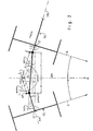
- Figure 1 shows a top view of a tractor TR with a attached trailer device AG of the same track width.
- a drawbar Z On the tractor TR there is a drawbar Z, in which an articulated drawbar D is mounted on the other hand with the fixed drawbar in Kink point KP of the trailer device is connected.
- An actuator AK is placed over the joint in the break point KP the kink angle is adjustable.
- a Microprocessor MP arranged with at least one Angle sensor Wd on the hitch Z or an angle sensor W ⁇ on Kink point is connected on the input side and at least one second sensor G, a gyroscope connected to the tractor TR, if only one of the two angle sensors W ⁇ , W ⁇ is present, and with at least one displacement sensor WS, which is preferably on the Trailer AG is arranged.
- the microprocessor MP controls the actuator AK.
- the steering control works either with the calculated Path radius and an angle sensor measured value ⁇ , ⁇ or with these both and controls with one depending on these value pairs determined displacement the actuator AK so that the trailer AG if possible follows the tractor TR on the same track.
- the path signal is corresponding corrected the track radius of the respective trailer track or from the Travel signals from two travel signal transmitters on the two wheels are arranged, averaged.
- the articulation point joint is used for road travel with a lock SP blocked.
- a sensor SS reports the blockage to the processor MP, which then does not control the actuator.
- the tilt signal the Microprocessor MP is supplied as a further control variable for Modification of one of the measured angle sensor values ⁇ , ⁇ is used.
- a control processor LP is installed on the tractor TR a control keyboard TA and a display device DV and with the microprocessor MP is connected.
- the microprocessor MP is the first Geometric data of the handlebar components entered and the Sensor assembly communicated so that the universal equations to determine the target size for the actuator loading in each case can be calculated.
- the TA While driving, the TA are on the keyboard Activation of the steering control for curve compensation and if necessary Controllable for slope compensation.
- the size is the Slope components in the control loop by key input modifiable, the modifier and the status and possibly a Alarm can be shown on the display device.
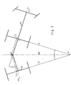
- FIG. 2 shows the steering scheme with the previously defined geometric sizes.
- the center ST of the tractor axle has Glasmaul Z the distance LT.
- the tractor center line TM extends with the distance y up to the virtual articulation point A.
- the middle the trailer axle S2 has the distance LS from the break point KP Articulated drawbar D.
- the fixed drawbar hits the distance x thought extends the articulation point A.
- the length of the articulated drawbar D is indicated by LD, so that the Total length of the handlebar components between the axle points ST, S2 results from the three lengths LS + LD + Lt.
- the tractor TR is steered on a circular path with the Radius R, which extends from a center point M to the axis point ST extends, so the trailer AG follows in the same circle, with the radius R around the center point M if the virtual break point A lies on the center line RM between the axis points ST, S2.
- the articulated drawbar D On the drawbar Z, the articulated drawbar D then has an angle ⁇ to Tractor center line TM, and to the drawbar break point KP has Articulated drawbar D an angle ⁇ to the trailer center line AG.
- These angles ⁇ and ⁇ together correspond to the angle ⁇ , between the two radii R to the axis points ST, S2.
- the angle ⁇ occurs also between the two center lines TM, AM.
- Fig. 3 illustrates the case of a circular trip.
- the two distances a of the virtual articulation point A to the two axis points ST, S2 are the same size. This figure always applies regardless of whether there is an articulated drawbar or the trailer wheels Has steering knuckle steering and how long the individual handlebar components are relative.
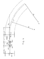
- Fig. 4 shows a schematic of the tracks and wheels of the tractor TR and of the trailer AG and the axle points ST, S2 and the towing jaw Z when entering in the direction of travel F into a circular arc.
- the actuator AK at the break point KP the Articulated drawbar angle ⁇ , the one on the towing hitch Z from the other Angle encoder W ⁇ is measured, changed.
- an actuator AK can be arranged on the hitch Z, the Angle ⁇ must be set appropriately.
- the actuators AK, AK1 are each controlled in a control loop that the target angle specified by the microprocessor ⁇ , ⁇ with corresponds to the measured actual angle ⁇ , ⁇ as far as possible.
- the actuator AK and the angle encoder of the controlled system do not have to be the same Hinge point Z, KP can be arranged.
- a section of the track is in the further course by summation of partial section courses over a path length which corresponds to the distance between the axis points ST, S2, as shown above, constantly determined.
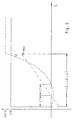
- Equation (7) illustrates the entry into the circular arc according to FIG. 4 the course of the transition function Hcs over the route according to Equation (7) and the desired angle ⁇ according to equations (8) - (10), where the respective radius R (s) e.g. by means of a gyrator measurement is assumed to be known.
- the optimal angle ⁇ is the direction in the course of the Path changes, with an extremum where the towing jaw Z has reached roughly the starting position of the tractor axle point s1 and the angle ⁇ has the value zero after twice the distance Lt. Then it increases gradually to the final value, which is caused by the Geometry and the circle radius R is determined by what The trailer axle enters the circular arc.
- angle ⁇ of the articulated joint is considered, as this Best for the attachment of the angle sensor W ⁇ and the Actuator AK is suitable, since the hitch Z is usually used as one Standard connection is expanded and so most essential Control elements can be arranged firmly on the trailer.
Abstract
Description
Die Erfindung betrifft ein Verfahren zur Nachführung eines Anhängegerätes, das hinter einem Traktor mittels einer Knickdeichsel oder mit einer Achsschenkellenkdeichsel gelenkig an einem Zugmaul angehängt ist, wobei ein Deichselgelenk mit dem von einer Regelvorrichtung, der ein traktorseitiges Winkelmeßsignal und ein anhängerseitiges Winkelmeßsignal zugeführt sind, angesteuerten Aktor derart winkelstellend geregelt angesteuert wird, daß das Anhängegerät bei Kurvenfahrt möglichst exakt dem Traktor folgt.The invention relates to a method for tracking a Trailer that is behind a tractor by means of a Articulated drawbar or articulated with a steering knuckle drawbar is attached to a hitch, a drawbar joint with that of a control device that a tractor-side angle measurement signal and a trailer-side angle measurement signal are supplied, controlled actuator controlled in such a controlled angular position is that the trailer when cornering as exactly as possible Tractor follows.
In der Landwirtschaft werden zur Pflege der Ackerfrüchte zum
überwiegenden Teil an eine Zugmaschine angehängte Geräte genutzt.
Als Zugmaschine finden in der Regel Traktoren Verwendung, welche
dem angehängten Gerät über Zapfwelle, Spannungsversorgung oder
Hydraulikkreise Energie zur Verfügung stellen. Die vielfältige
Energie wird genutzt, um die vielfältigen Aufgaben, wie Spritzen,
Säen, Dünger verteilen, Schwad aufnehmen usw. durchzuführen.
Viele der angehängten Geräte werden im aufgelaufenen Bestand
genutzt. Um den Bestand nicht zu zerstören, benutzen die Pflegekombinationen
in der Regel Fahrgassen, die schon beim Säen in der
richtigen Pflegebreite angelegt werden. Angehängte Geräte haben
aber gewöhnlich den Nachteil, daß sie sich in Kurvenfahrten so
verhalten, daß sie die Kurve abkürzen wollen und nicht im gleichen
Radius wie die Zugmaschine laufen. Dieses wiederum zerstört den
Bestand, der neben der Fahrgasse angepflanzt wurde und mindert den
Ertrag des Landwirtes. In agriculture, most of the equipment attached to a tractor is used to care for the crops. Tractors are generally used as the tractor, which provide energy to the attached implement via a PTO shaft, power supply or hydraulic circuits. The diverse energy is used to carry out the diverse tasks such as spraying, sowing, distributing fertilizer, picking up swaths, etc.
Many of the attached devices are used in the accumulated inventory. In order not to destroy the crop, the maintenance combinations generally use tramlines, which are already created in the correct maintenance width when sowing. Attached devices usually have the disadvantage that when cornering they behave in such a way that they want to shorten the curve and do not run in the same radius as the tractor. This in turn destroys the crop that was planted next to the Fahrgasse and reduces the farmer's yield.
In ESDERS H. et al: "Entwicklungen und Tendenzen der Hydraulik in Traktoren und Landmaschinen", O+P Olhydraulik und Pnaumatik, Krausskopf Verlag für Wirtschaft GmbH, DE-Mainz, Bd. 38, Nr. 4, 1. April 1994 (1994-04-01), Seiten 202-211, XP000454266, ISSN: 0341-2660, ist beschrieben, daß an der eingangs bezeichneten Lenkvorrichtung Winkelmeßsignale von den Gelenken der Deichsel abgenommen werden, aus denen anhand von gespeicherten Erfahrungswerten ein Sollsignal für die Beaufschlagung des elektro-hydraulischen Stellgliedes so abgeleitet wird, daß eine möglichst genaue Spurfolge des Anhängers erreicht wird. Zum Ausgleich von Lenkfehlern am Hang kann manuell in den Regelprozeß eingegriffen werden. Bei Straßenfahrten wird der Regler verriegelt. Die Erstellung der Erfahrungswertedatei ist relativ aufwendig und muß für jede Gespannart neu erarbeitet werden. Mangels eines Wegsignales besteht kein eindentiger zusammenhang zwischen den gemessenen Winkeln und einem Sollwinkel.In ESDERS H. et al: "Developments and Trends in Hydraulics in Tractors and Agricultural Machinery ", O + P Olhydraulik und Pnaumatik, Krausskopf Verlag für Wirtschaft GmbH, DE-Mainz, Vol. 38, No. 4, April 1, 1994 (1994-04-01), pages 202-211, XP000454266, ISSN: 0341-2660, it is described that at the beginning Steering device angle measurement signals from the joints of the drawbar be removed from which saved A target signal for the application of the electro-hydraulic actuator is derived so that a as accurate as possible tracking of the trailer is achieved. To the Compensation for steering errors on slopes can be done manually in the control process be intervened. The controller is used when driving on the road locked. The creation of the empirical value file is relative complex and must be worked out for each type of trailer. In the absence of a path signal, there is no one-size-fits-all connection between the measured angles and a target angle.
Weiterhin ist aus der japanischen Patentschrift 04149966, "METHOD FOR STEERING AND CONTROLLING AGRICULTURAL TRACTION TYPE WORKING MACHINE", Inhaber: Seibutsukei Tokutei Sangyo Gijutsu Kenkyu Suishin Kiko, eine Achsschenkellenkvorrichtung bekannt, bei der am Anhängermaul ein Winkelmeßsignal abgenommen wird, aus dem ein Stellsignal für eine Lenkungseinstellung gewonnen wird, wodurch ein fiktiver Punkt, der auf der Traktormitellinie zwischen der Vorder- und Hinterradachse liegt, symmetrisch zur Hinterachse bezüglich eines gewählten Punktes auf der Verbindungslinie des Anhängermauls mit der Anhängerachsenmitte liegt. Die Nachlaufgenauigkeit ist fehlerbehaftet und geschwindigkeitsabhängig.Furthermore, from Japanese Patent 04149966, "METHOD FOR STEERING AND CONTROLLING AGRICULTURAL TRACTION TYPE WORKING MACHINE ", owner: Seibutsukei Tokutei Sangyo Gijutsu Kenkyu Suishin Kiko, a steering knuckle device known in the Trailer mouth an angle measurement signal is taken from which a Control signal for a steering setting is obtained, whereby a fictional point on the tractor center line between the The front and rear wheel axles are symmetrical to the rear axle regarding a selected point on the connecting line of the Trailer mouth lies with the middle of the trailer axle. The Tracking accuracy is error-prone and speed-dependent.
Aufgabe der Erfindung ist es, die eingangs bezeichneten Anordnungen so zu verbesern, daß verschiedenartige angehängte Geräte damit ohne die Erzeugung von Erfahrungswerten in engen Grenzen "in der Spur" der Zugmaschine gehalten werden können. The object of the invention is to designate those mentioned at the beginning Improve arrangements so that different types of attached Devices with it without the generation of empirical values in narrow Limits can be kept "on track" of the tractor.
Die Lösung besteht darin, daß die Regelvorrichtung eingangsseitig mit mindestens einem Wegsignalgeber verbunden ist und aus dessen Wegsignal sowie den Winkelmeßsignalen jeweils ein Soll-Deichselgelenkwinkel für dessen geregelte Einstellung mit dem Aktor so errechnet wird, daß der jeweilige Schnittpunkt von einer Traktormittellinie und einer Anhängermittellinie als ein virtueller Anlenkpunkt jeweils, wenn sich diese auf einer Kreisbahn befinden, äquidistant zu Achsmittelpunkten einer Traktorachse und einer Anhängerachse geführt wird.The solution is that the control device on the input side is connected to at least one displacement signal generator and from the latter Travel signal and the angle measurement signals each a target drawbar joint angle for its regulated setting with the Actuator is calculated so that the respective intersection of one Tractor centerline and a trailer centerline as one virtual articulation point each time this is on a Circular path are equidistant to the center of an axis Tractor axle and a trailer axle is guided.
Vorteilhafte Ausgestaltungen sind in den Unteransprüchen angegeben. Eine Vorrichtung zur Durchführung des Verfahrens ist in den Ansprüchen 11 und 12 beansprucht.Advantageous configurations are in the subclaims specified. A device for performing the method is in claims 11 and 12.
Die Gesamtanordnung besteht aus einer Zugmaschine, einem angehängten Gerät, welches mit einer Knickdeichsel oder eine Achsschenkellenkung versehen ist, einer Vorrichtung zur Verstellung der Knickdeichsel oder der Achsschenkellenkung, einer Vorrichtung zur Steuerung dieser Verstellvorrichtung sowie Meßwertaufnehmern zur Messung des Zugmaulwinkels, des Knickwinkels oder Achsschenkelwinkels und zur Aufnahme der Winkelgeschwindigkeit des Zugfahrzeuges (Gyroscop) und ggf. eines Sensors zur Ermittlung der Neigung des gezogenen Fahrzeugs sowie eines Wegsensors.The overall arrangement consists of a tractor, a attached device, which with an articulated drawbar or a steering knuckle is provided, a device for adjustment the articulated drawbar or steering knuckle, a device to control this adjustment device and transducers for measuring the jaw angle, the articulation angle or Knuckle angle and for recording the angular velocity of the Towing vehicle (gyroscope) and possibly a sensor for determining the Inclination of the towed vehicle and a displacement sensor.
Über die Sensoren erhält die Steuervorrichtung fortlaufend
Eingangssignale, die es in Ausgangssignale zur Steuerung der
Einstellung der Knickdeichsel bzw. der Achsschenkellenkung
umsetzt. Bei den Eingangssignalen sind folgende Kombinationen
denkbar, wenn zwei Sensoren genutzt werden.
erster Sensor zweiter Sensor
Messung Winkelgeschwindigkeit und Knickdeichselwinkels (β)
Messung Winkelgeschindigkeit und Achsschenkelwinkels (β)
Messung Winkels am Zugmaul(α) und Knickdeichselwinkels (β)
Messung Winkels am Zugmaul(α) und Knickdeichselwinkels (β)The control device continuously receives input signals via the sensors, which it converts into output signals for controlling the setting of the articulated drawbar or the steering knuckle. The following combinations of the input signals are conceivable if two sensors are used.
first sensor second sensor
Measurement of angular velocity and articulated drawbar angle (β)
Measurement of angular velocity and steering knuckle angle (β)
Measurement of the angle on the towing jaw (α) and articulated drawbar angle (β)
Measurement of the angle on the towing jaw (α) and articulated drawbar angle (β)
Für die Ausgangssignale ist es unerheblich, ob damit die Achsschenkel oder die Knickdeichsel verstellt wird. Auch ist es unerheblich, ob die aufgebrachte Kraft zur Verstellung über ein Hydrauliksystem, ein Pneumatiksystem oder elektromotorisch erfolgt.For the output signals it is irrelevant whether the Steering knuckle or the articulated drawbar is adjusted. It is too irrelevant whether the force applied for adjustment via a Hydraulic system, a pneumatic system or an electric motor he follows.
Ein Sicherheitsbolzen vervollständigt die Anordnung. Er wird benutzt, um sie z.B. bei Straßenfahrten zu verriegeln.A safety bolt completes the arrangement. He will used to e.g. lock when driving on the road.
Um zu den Meßwerten die entsprechenden Sollsignale zu ermitteln, wird folgende Implikationskette benutzt:To determine the corresponding target signals for the measured values, the following chain of implications is used:
Aus dem Radius R des Kreises auf dem sich die Zugmaschine befindet, wird ein Gesamtwinkel γ zwischen der Zugmaschine und dem gezogenen Gerät errechnet.From the radius R of the circle on which the tractor is located is a total angle γ between the tractor and the drawn device.
Aus dem Gesamtwinkel γ wird die Stellung des Winkels α, β an dem Zugmaul der Zugmaschine sowie an der Knickdeichsel oder den Achsschenkeln ermittelt.From the total angle γ the position of the angle α, β at the Traction jaw of the tractor and on the articulated drawbar or Knuckles determined.
Laufend wird aus der Änderung des Radius R des Kreises, auf dem sich die Zugmaschine befindet, mit Hilfe einer Übertragungsfunktion die Änderung des Winkels β an der Knickdeichsel oder den Achsschenkeln ermittelt. Die Übertragungsfunktion wird aus geometrischen Größen der Anordnung bestimmt. Dieses ist insbesondere wichtig für den möglichst spurgetreuen Übergang beim Hineinfahren in und Herausfahren aus einer Kurve.The change in radius R of the circle on which the tractor is located using a transfer function the change in the angle β on the articulated drawbar or the Knuckles determined. The transfer function is turned off geometric sizes of the arrangement determined. This is particularly important for the transition that is as true to the track as possible Driving in and out of a curve.
Da sich der Gesamtwinkel γ zwischen der Zugmaschine und dem gezogenen Gerät aber nur dann eindeutig bestimmten läßt, wenn der Anlenkpunkt fest ist, hier aber ein variabler "imaginärer" Anlenkpunkt eingeführt ist, wird durch ein Iterationsverfahren der Fehler bei der Berechnung beliebig klein gehalten.Since the total angle γ between the tractor and the drawn device can only be clearly determined if the Articulation point is fixed, but here a variable "imaginary" Articulation point is introduced by an iteration process Errors in the calculation kept as small as possible.
Bei den nachfolgenden Berechnungen gilt folgende Notation
- R:
- = Radius des Kreises, auf dem sich der Schnittpunkt zwischen der Mittelachse des ziehenden Fahrzeugs und seiner Hinterachse bewegt,
- M:
- = Mittelpunkt des Kreises auf dem sich das ziehende Fahrzeug bewegt
- ST:
- = Schnittpunkt der Mittelachse des ziehenden Fahrzeugs und seiner Hinterachse (Hinterachspunkt)
- S2:
- = Schnittpunkt der Mittelachse des gezogenen Fahrzeuges und seiner Achse (Hängerachspunkt)
- A:
- = Anlenkpunkt zwischen den beiden Fahrzeugen (virtuell)
- α
- = Winkel zwischen der Mittelachse des ziehenden Fahrzeugs und der Deichsel D am Zugmaul Z
- β
- = Winkel zwischen der Knickdeichsel und der Mittelachse des gezogenen Fahrzeugs oder Winkel an den Achsschenkeln
- γ
- = Gesamtwinkel zwischen der Mittelachse des ziehenden Fahrzeugs und der Mittelachse des gezogenen Fahrzeugs oder zur gedachten Achse parallel zu den Achsschenkeln
- LT:
- = Abstand zwischen dem Hinterachspunkt ST und dem Zugmaul Z -Zugmaulabstand-
- LD:
- = der Knickdeichsel D
- LS:
- = Abstand zwischen dem Hängeachspunkt S2 und dem Knickpunkt KP -(bei Achsschenkellung ist LS = 0)-
- R:
- = Radius of the circle on which the intersection between the central axis of the pulling vehicle and its rear axle moves,
- M:
- = Center of the circle on which the pulling vehicle is moving
- ST:
- = Intersection of the central axis of the pulling vehicle and its rear axle (rear axle point)
- S2:
- = Intersection of the central axis of the towed vehicle and its axis (suspension axle point)
- A:
- = Articulation point between the two vehicles (virtual)
- α
- = Angle between the central axis of the pulling vehicle and the drawbar D on the hitch Z
- β
- = Angle between the articulated drawbar and the central axis of the towed vehicle or angle on the steering knuckles
- γ
- = Total angle between the central axis of the pulling vehicle and the central axis of the towed vehicle or to the imaginary axis parallel to the steering knuckles
- LT:
- = Distance between the rear axle point ST and the hitch Z-towing distance-
- LD:
- = the articulated drawbar D
- LS:
- = Distance between the suspension axis point S2 and the break point KP - (with axle pivoting LS = 0) -
Bei den nachfolgenden Ausführungen wird fast immer davon ausgegangen, daß eine Knickdeichsellenkung vorhanden ist. Die Ausführungen haben aber auch für die Achsschenkellenkung Gültigkeit. Man setzt dafür einfach den Abstand LS von Hängerachspunkt S2 zum Knickpunkt KP als Null.In the following explanations, almost always assumed that there is an articulated steering. The versions also have axle steering Validity. To do this, simply set the distance LS from Suspension axis point S2 to the break point KP as zero.
Bei äquidistantem Abstand zwischen den Hinterachspunkt ST und dem Anlenkpunkt A sowie dem Hängerachspunkt S2 und dem Anlenkpunkt A ist ersichtlich, daß sich beide Achspunkte auf dem gleichen Radius bewegen, was der spurgetreuen Nachführung des gezogenen Fahrzeugs entspricht.With an equidistant distance between the rear axle point ST and the Articulation point A and the trailer axle point S2 and articulation point A it can be seen that both axis points are on the same radius move what the true tracking of the towed vehicle equivalent.
Der Winkel γ, der sich zwischen dem gezogenen und dem ziehenden
Fahrzeug nach einer Übergangszeit einstellt, unter der
Voraussetzung, daß die Achspunkte ST, S2 äquidistant von dem
Anlenkpunkt liegen, kann aus dem Radius R auf dem sich der
Hinterachspunkt ST bewegt und der Länge a zwischen diesem und dem
Anlenkpunkt A ermittelt werden.

Wie gezeigt, folgt ein gezogenes Fahrzeug auf einem Kreis in der Spur des ziehenden genau dann, wenn der Anlenkpunkt äquidistant zwischen den beiden Fahrzeuge liegt, es stellt sich dann ein Gesamtwinkel γ ein.As shown, a towed vehicle follows a circle in the Track the pulling precisely when the articulation point equidistant lies between the two vehicles, it then sets in Total angle γ.
Mit Hilfe der Knickdeichsel werden deshalb an ihr die Winkel α und
β so verstellt, daß der Schnittpunkt der Verlängerungen der
Mittelachsen der beiden Fahrzeuge genau äquidistant zu den beiden
Fahrzeugen im imaginären Schnittpunkt A liegt.
Dieses ist genau dann erreicht, wenn LS + X = LT + y gilt, wobei
This is achieved when LS + X = LT + y, where
Bei weiteren Berechnungen werden LS, LT und LD als Maße aus der
Geometrie des Systems und aus den Berechnungen des vorangegangenen
Kapitels als bekannt vorausgesetzt.
Weiterhin gilt γ' = 180° - γ. Für Dreiecke allgemein gilt die Summe
der Innenwinkel = 180°, also α + β + γ; die Summe der Einzelwinkel
ist der Gesamtwinkel. For further calculations, LS, LT and LD are assumed to be known as dimensions from the geometry of the system and from the calculations in the previous chapter.
Furthermore, γ '= 180 ° - γ. For triangles in general, the sum of the inner angles = 180 °, ie α + β + γ; the sum of the individual angles is the total angle.
Mit Hilfe der Projektionen x' und y' der Abstände x bzw. y auf die
Deichsel D ergeben sich:


Desweiteren ist aus dieser Projektion ein Winkel δ abzuleiten.
δ läßt sich aus bekannten Größen bestimmen. Mit dem Sinussatz gilt
nämlich:
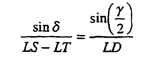
Nach δ ausgelöst ergibt sich:

Aus (3) und (4) folgt dann

Durch Substituierung des Kosinausdruckes in (3') mit Hilfe einer
Strukturkonstanten (K) und mit Hilfe von (2) und (2')
läßt sich nun schreiben:
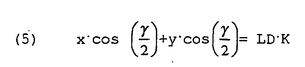
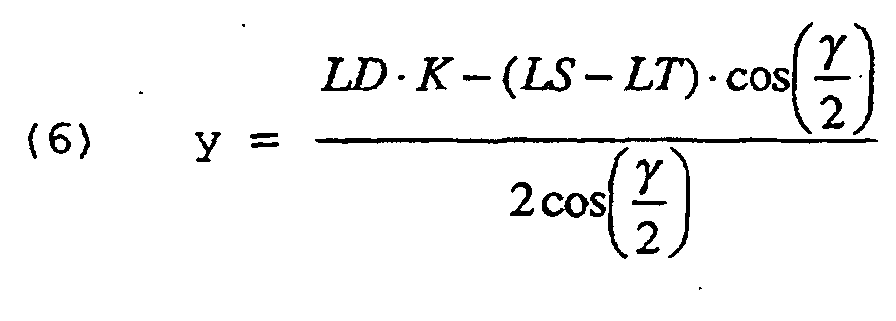
(5) und (1) sind zwei Gleichungen für die zwei Unbekannten, welche
ergeben:


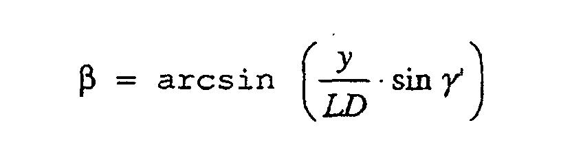
Über die Sinussätze lassen sich nun auch die Winkel α und β
berechnen:

Somit läßt sich bei einer Bewegung des Traktors auf einem gegebenen Kreis jeweils bei gegebenen Abmessungen der Lenkerkomponenten LS, LT, LD, ein optimales Winkelpaar α, β bestimmen, bei dem die Spurtreue vorliegt.Thus, when the tractor moves on one given circle with given dimensions of the handlebar components LS, LT, LD, determine an optimal pair of angles α, β, at who is on track.
Der Übergang von der Geradeausfahrt in eine Kurve erfordert eine gesonderte Betrachtung. Ist bei einer ungeregelten Anordnung die Tendenz, die Kurve "abzukürzen" zu beobachten, erkennt man bei den bekannten geregelten Anordnungen, daß sich beim Einfahren in eine Kurve eine Tendenz zum "weiter ausholen" einstellt, welche ebenso den Bestand gefährdet.The transition from straight-ahead driving into a curve requires one separate consideration. In the case of an unregulated arrangement, that is The tendency to "shorten" the curve can be seen in the known regulated arrangements that when entering a Curve sets a tendency to "go further", which also endangered the existence.
Während das Zugfahrzeug schon mit der Kurvenfahrt beginnt, wird in vorteilhafter Ausgestaltung der Erfindung das gezogene Fahrzeug noch so lange in der Geradeausfahrt gehalten, bis es an der Stelle angekommen ist, wo das Zugfahrzeug die Kurvenfahrt begann.While the towing vehicle is already beginning to corner, in advantageous embodiment of the invention, the towed vehicle held straight ahead until it was in place has arrived where the towing vehicle started cornering.
Desweiteren fährt erfindungsgemäß das gezogene Fahrzeug beim Übergang von der Kurvenfahrt in die Geradeausfahrt die Kurve erst zu Ende.Furthermore, the towed vehicle drives according to the invention Transition from cornering to straight ahead the curve first over.
Mit Hilfe einer numerischen Simulation wird hier das gewünschte
Verhalten für den Übergang des Winkels β beim Einfahren und beim
Ausfahren in einer Kurve nachgebildet.
Bezogen auf den Weg kann dieser Übergang sehr gut durch eine
Polynom 2ten Grade approximiert werden:
In relation to the path, this transition can be approximated very well by a polynomial 2nd degree:
Um nun, wie in der Regelungstechnik allgemein üblich, aus dem
Eingangssignal das Ausgangssignal zu ermitteln, wird die
Übertragungsfunktion H(s) gesucht, welche für jede Änderung des
Radius R(s), d.h. der wegabhängigen Radiusfunktion den Sollwinkel
β = f(s) bestimmt.
R(S) sei für diesen Zeitraum konstant R(s) = Rs. Damit ergibt sich
Es sind nun die Koeffizienten des Polynoms zu bestimmen.The coefficients of the polynomial must now be determined.
Die Funktion muß den Zielwert β aus den früheren Berechnungen
erreichen, wenn das gezogene Fahrzeug an der Stelle angekommen
ist, an der das ziehende Fahrzeug die Kurve begonnen hat.
Wenn das ziehende Fahrzeug in die Kurve fährt, dann bewegt sich
der Anlenkpunkt des Zugmauls erst über die Linie der
Geradeausfahrt hinaus in die entgegengesetzte Richtung, da er sich
auf einem Kreis mit größerem Radius aber gleichem Mittelpunkt wie
der Hinterachspunkt ST befindet. Dieser Punkt hat den von der
Linie am weitesten entfernten Punkt erreicht, wenn er sich auf
gleicher Höhe mit dem Punkt befindet, wo der Traktor die
Kurvenfahrt begann. Das ist nach Durchfahren des Zugmaulabstandes
LT der Fall. Da ein Maximum vorliegt, gilt:
Ein Bezugssystem wird gewählt, bei dem der Funktionswert zum
Startpunkt bei 0 liegt, so daß
Bei j=0 dienen jetzt die 2 restlichen Gleichungen, die
verbleibenden Unbekannten zu bestimmen. Aus (9) folgt sofort:
Werden nun nacheinander mehrere Lenkbewegungen ausgeführt, dann
faßt man vorteilhaft die Radiusfunktion R(s) als Sprungänderung
des Eingangssignals auf dem zweiten Änderungsort R(s) =
Rs1 - Rs2 welche aber für den Weg LT+LS+LD, beginnend bei dem
ersten Änderungsort S1 bzw. dem zweiten Änderungsort S2 wieder
konstant gehalten wird. Die Zielwerte β können ebenfalls bestimmt
werden: β = β1 - β2.
Die Berechnungen für die einzelnen Werte für β ergeben sich aus
den vorigen Ausführungen. Damit gelten dann die obigen
Berechnungen für die Koeffizienten auch für diese Betrachtungen.
Die einzelnen Funktionen H1, H2,...Hn können also eindeutig
bestimmt werden.
The calculations for the individual values for β result from the previous explanations. The above calculations for the coefficients then also apply to these considerations. The individual functions H1, H2, ... Hn can therefore be clearly determined.
Die Übertragungsfunktionen H1(s)...Hn(s) sind nur für die gestreckte Länge LT+LS+LD der Lenkerkomponenten definiert und liefern ab einer bestimmten Strecke nur noch Nullen, so daß die Integrale konstant bleiben und damit fges(s), was dem Zustand entspricht, daß keine Lenkbewegungen mehr ausgeführt werden. Das kann in Geradeausfahrt, aber auch in der konstanten Kurvenfahrt der Fall sein.The transfer functions H1 (s) ... Hn (s) are only for straight length LT + LS + LD of the handlebar components defined and return only zeros from a certain distance, so that the Integrals remain constant and thus fges (s), which is the state corresponds to the fact that no steering movements are carried out. The can drive straight ahead, but also when cornering constantly be the case.
Faßt man die Radiusfunktion R(s) als Sprungänderung auf, dann ist auch ersichtlich, daß die Radiusfunktion R(s) negativ werden kann. Für die Übertragungsfunktion wird dann der Parameter h negativ, was einer Umkehrung der Parabel entspricht. Dieses kommt zum Tragen, wenn die Kurvenfahrt beendet wird und in die Geradeausfahrt gelenkt wird oder aber von der Geradeausfahrt in die andere Richtung gelenkt wird.If one takes the radius function R (s) as a jump change, then also apparent that the radius function R (s) can become negative. The parameter h then becomes negative for the transfer function, which corresponds to an inversion of the parabola. This comes to Wear when cornering is finished and into the Straight ahead is steered or from the straight ahead in the other direction is steered.
Oben wurde gezeigt, daß der Winkel γ von dem Abstand a des
Hinterachsenpunktes ST vom Anlenkpunkt A abhängig ist und die
Abstandskomponente y wiederum mit dem Winkel γ zusammenhängt. Für
eine Berechnung eines jeweiligen Winkels y mit einem
Mikroprozessor in einer akzeptablen Zeit, wobei der Fehler so
klein wie praktisch zulässig sein soll, wird nachfolgend ein
Iterationsverfahren
angegeben.
Mit dem Startwert

With the starting value
Der nächste Wert y1 wird dann nach der Formel (6) bestimmt:

Daraus wird dann γ1 bestimmt und so weiter, bis die Abschätzung
Untersuchungen mit bekannten Geometrien haben ergeben, daß nach dem ersten Iterationsschnitt der Fehler kleiner als ein Promille ist und der Funktionswert nach dem dritten Iterationsschritt keine signifikante Änderung mehr erfährt.Studies with known geometries have shown that after the first iteration cut the error is less than one per thousand and the function value after the third iteration step undergoes no significant change.
Im hängigen Gelände tendiert ein quer zum Hang oder schräg zum Hang gezogenes Fahrzeug leicht dazu, talwärts auszubrechen, was im Falle der gezogenen landwirtschaftlichen Fahrzeuge eine Zerstörung des Bestandes zur Folge hat. Lenkt man nun das angehängte Fahrzeug im geeigneten Maße berghoch, gleicht es diese talwärts gerichtete Tendenz wieder aus und das Fahrzeug bleibt in der Spur.In sloping terrain, one tends to cross the slope or at an angle vehicle pulled to the slope slightly to break downhill, which in the case of towed agricultural vehicles Destruction of the stock. If you steer that now hitched vehicle up to a suitable height, it resembles this downward trend again and the vehicle remains in the trace.
Mit Hilfe eines Neigungsmessers, welche die seitliche Neigung des gezogenen Fahrzeugs zur Erdanziehungskraft miß und damit ein Maß für die seitliche Neigung des befahrenen Hanges angibt, wird die Lenkung des angehängten Fahrzeug dergestalt verstellt, daß sich die talabwärts ziehenden Kräfte und die bergwärts gerichtete Lenkwirkung ausgleichen. With the help of an inclinometer, which measures the lateral inclination of the towed vehicle to earth gravity and thus one Measure of the lateral inclination of the slope used indicates the steering of the attached vehicle is such adjusted that the downward forces and the Compensate uphill steering effects.
Die talwärts ziehende Kraftwirkung kann nur abgeschätzt und nicht direkt berechnet werden, da sie von Faktoren wie Gewicht, Gewichtsverteilung, Bodenbeschaffenheit und Bereifung abhängig ist. Deshalb wird dem Benutzer über eine Bedieneinrichtung die Möglichkeit gegeben, das Maß der korrigierenden Verstellung der Lenkung angemessen zu erhöhen oder zu mindern.The downward force effect can only be estimated and not can be calculated directly because of factors such as weight, Weight distribution, soil conditions and tires dependent is. The user is therefore provided with an operating device Possibility given the degree of corrective adjustment of the Increase or decrease steering appropriately.
Die in den vorangegangenen Kapiteln vorgestellt Lenkstrategie und die die Hangfahrt verbessernde Lenkstrategie wirken vorzugsweise zugleich.The steering strategy presented in the previous chapters and the steering strategy that improves slope driving preferably work at the same time.
Der Benutzer erhält vorzugsweise die Möglichkeit, über verschiedene Regelstrategien ein- oder abzuschalten. Die Tasten dazu können an einem Multifunktionsgriff angeordnet sein. Dabei ist immer eine Möglichkeit gegeben, daß der Benutzer das Regelsystem übersteuert und damit auch die Regelung deaktiviert. Über eine besondere Sperre läßt sich ein Zustand einstellen, der eine Aktivierung der Regelung unmöglich macht. Der Benutzer wird vorzugsweise über einen Bildschirm über den Zustand der eingestellten Regelstratergien informiert. Desweiteren werden dort vorzugsweise Alarme angezeigt, die auf mögliche Gefahren bei einer extremen Geländeneigung oder extremen Lenkeinschlag sowie auf fehlerhafte Sensoren und Aktoren hinweisen.The user is preferably given the opportunity to switch on or off various control strategies. The button's can be arranged on a multi-function handle. there there is always a possibility that the user can Control system overridden and thus also the control deactivated. A state can be set via a special lock an activation of the regulation makes it impossible. The user will preferably via a screen about the state of the set regular strategies. Furthermore, there preferably alarms that indicate possible dangers in the event of a extreme terrain or extreme steering angle as well point out faulty sensors and actuators.
Um den Radius des zu ziehenden Fahrzeuges unmittelbar eindeutig
bestimmen zu können, wird auf diesem eine Gyroscope G installiert.
Das Gyroscope gibt ein analoges Signal ab, welches direkt
proportional zur Winkelgeschwindigkeit des Traktors in der
Horizontalebene ist. Mit Hilfe der tatsächlichen Geschwindigkeit,
welche über einen Wegsensor WS gewonnen wird, kann der jeweilige
eingeschlagene Radius R ermittelt werden und somit als ein von den
Deichselwinkeln α, β unabhängiges Eingangssignal für die Steuerung
dienen.
Es gilt nämlich:
The following applies:
Vorteilhafte Ausgestaltungen sind in den Unteransprüchen angegeben.
- Fig. 1
- zeigt eine Aufsicht auf ein Traktor-Hänger-Anordnung;
- Fig. 2
- zeigt eine geometrische Lenkungsschema;
- Fig. 3
- zeigt ein spurtreues idealisiertes Lenkungsschema;
- Fig. 4
- zeigt einen Fahrwegverlauf bei, sprunghafter Kurveneinfahrt;
- Fig. 5
- zeigt beispielhaft wegabhängig die Verläufe der Übertragungsfunktion und des Lenkerwinkels β zu Fig. 4.
- Fig. 1
- shows a top view of a tractor-trailer arrangement;
- Fig. 2
- shows a geometric steering scheme;
- Fig. 3
- shows a directional idealized steering scheme;
- Fig. 4
- shows a route in the case of sudden corner entry;
- Fig. 5
- shows, by way of example, the curves of the transfer function and the handlebar angle β to FIG. 4 as a function of the path.
Figur 1 zeigt eine Aufsicht auf einen Traktor TR mit einem angehängten Anhängergerät AG gleicher Spurweite. An dem Traktor TR befindet sich ein Zugmaul Z, in das eine Knickdeichsel D eingehängt ist, die andererseits mit der festen Deichsel im Knickpunkt KP des Anhängergerätes verbunden ist.Figure 1 shows a top view of a tractor TR with a attached trailer device AG of the same track width. On the tractor TR there is a drawbar Z, in which an articulated drawbar D is mounted on the other hand with the fixed drawbar in Kink point KP of the trailer device is connected.
Über das Gelenk im Knickpunkt KP ist ein Aktor AK gelegt, durch den der Knickwinkel einstellbar ist. Am Anhänger AG ist ein Mikroprozessor MP angeordnet, der mit mindestens einem Winkelsensor Wd am Zugmaul Z oder einem Winkelsensor Wβ am Knickpunkt eingangsseitig verbunden ist und mindestens mit einem zweiten Sensor G, einem Gyroscop auf dem Traktor TR verbunden ist, falls nur einer der beiden Winkelsensoren Wα, Wβ vorhanden ist, sowie mit mindestens einem Wegsensor WS, der vorzugsweise auf dem Anhänger AG angeordnet ist. An actuator AK is placed over the joint in the break point KP the kink angle is adjustable. At the trailer AG is a Microprocessor MP arranged with at least one Angle sensor Wd on the hitch Z or an angle sensor Wβ on Kink point is connected on the input side and at least one second sensor G, a gyroscope connected to the tractor TR, if only one of the two angle sensors Wα, Wβ is present, and with at least one displacement sensor WS, which is preferably on the Trailer AG is arranged.
Ausgangsseitig steuert der Mikroprozessor MP den Aktor AK.On the output side, the microprocessor MP controls the actuator AK.
Aus dem Gyroscopsignal, das laufend die Änderung der Winkellage in der Horizontalebene angibt, und dem Weggebersignal wird der Kurvenradius laufend errechnet, der bei gelenkt eingeschlagenen Rädern des Traktors gefahren wird. Selbstverständlich können auch alle Räder gelenkt sein, da das Gyroscop davon unabhängig die Winkellagenänderung in der Horizontalebene mißt.From the gyroscope signal, which continuously changes the angular position in indicates the horizontal plane, and the encoder signal is the Curve radius calculated continuously, the one with steered Wheels of the tractor is driven. Of course you can too all wheels are steered, since the gyroscope is independent of the Measures angular position change in the horizontal plane.
Die Lenkungsregelung arbeitet entweder mit dem so errechneten Bahnradius und einem Winkelsensormeßwert α, β oder mit diesen beiden und steuert abhängig von diesen Wertepaaren mit einem bestimmten Wegversatz den Aktor AK so an, daß der Anhänger AG möglichst dem Traktor TR auf der gleichen Spur folgt.The steering control works either with the calculated Path radius and an angle sensor measured value α, β or with these both and controls with one depending on these value pairs determined displacement the actuator AK so that the trailer AG if possible follows the tractor TR on the same track.
Da bei der Kurvenfahrt der Wegsensor WS außenliegend einen längeren Weg mißt als innenliegend wird das Wegsignal entsprechend dem Bahnradius der jeweiligen Anhängerbahn korrigiert oder aus den Wegsignalen zweier Wegsignalgeber die an den beiden Rädern angeordnet sind, gemittelt.As the travel sensor WS is on the outside when cornering If the path is longer than the inside, the path signal is corresponding corrected the track radius of the respective trailer track or from the Travel signals from two travel signal transmitters on the two wheels are arranged, averaged.
Das Knickpunktgelenk wird für die Straßenfahrt mit einer Sperre SP blockiert. Ein Sensor SS meldet die Blockade an den Prozessor MP, der den Aktor dann nicht ansteuert.The articulation point joint is used for road travel with a lock SP blocked. A sensor SS reports the blockage to the processor MP, which then does not control the actuator.
Als vorteilhafte Ergänzung ist auf dem Anhänger AG ein Seitenneigungssensor NS installiert, dessen Neigungssignal dem Mikroprozessor MP zugeführt ist, das als weitere Steuergröße zur Modifikation eines der gemessenen Winkelsensorwertes α, β dient. As an advantageous addition is on the trailer AG Side tilt sensor NS installed, the tilt signal the Microprocessor MP is supplied as a further control variable for Modification of one of the measured angle sensor values α, β is used.
Auf den Traktor TR ist ein Leitprozessor LP installiert, der mit einer Bedientastatur TA und einer Anzeigevorrichtung DV sowie mit dem Mikroprozessor MP verbunden ist.A control processor LP is installed on the tractor TR a control keyboard TA and a display device DV and with the microprocessor MP is connected.
Über die Tastatur TA werden dem Mikroprozessor MP vorab die geometrischen Daten der Lenkerkomponenten eingegeben und die Sensorbestückung mitgeteilt, so daß die universellen Gleichungen zur Ermittlung der Sollgröße für die Aktorbeaufschlagung jeweils errechnet werden können.Using the keyboard TA, the microprocessor MP is the first Geometric data of the handlebar components entered and the Sensor assembly communicated so that the universal equations to determine the target size for the actuator loading in each case can be calculated.
Während des Fahrvorganges sind über die Tastatur TA die Aktivierungen der Lenkungssteuerung zum Kurvenausgleich und ggf. zur Hangfahrtausgleich steuerbar. Vorzugsweise ist die Größe der Hangfahrtkomponenten im Regelkreis durch Tasteneingabe modifizierbar, wobei der Modifikator und der Status- und evtl. ein Alarm auf der Anzeigevorrichtung dargestellt werden.While driving, the TA are on the keyboard Activation of the steering control for curve compensation and if necessary Controllable for slope compensation. Preferably the size is the Slope components in the control loop by key input modifiable, the modifier and the status and possibly a Alarm can be shown on the display device.
Figur 2 zeigt das Lenkschema mit den zuvor definierten geometrischen Größen. Die Mitte ST der Traktorachse hat zum Zugmaul Z den Abstand LT. Die Traktormittellinie TM erstreckt sich mit dem Abstand y bis zu dem virtuellen Anlenkpunkt A. Die Mitte der Anhängerachse S2 hat den Abstand LS vom Knickpunkt KP der Knickdeichsel D. Die feste Deichsel trifft um den Abstand x gedacht verlängert den Anlenkpunkt A.Figure 2 shows the steering scheme with the previously defined geometric sizes. The center ST of the tractor axle has Zugmaul Z the distance LT. The tractor center line TM extends with the distance y up to the virtual articulation point A. The middle the trailer axle S2 has the distance LS from the break point KP Articulated drawbar D. The fixed drawbar hits the distance x thought extends the articulation point A.
Die Länge der Knickdeichsel D ist mit LD angegeben, so daß die Gesamtlänge der Lenkerkomponenten zwischen den Achspunkten ST, S2 sich aus den drei Längen LS + LD + Lt ergibt.The length of the articulated drawbar D is indicated by LD, so that the Total length of the handlebar components between the axle points ST, S2 results from the three lengths LS + LD + Lt.
Befindet sich der Traktor TR gelenkt auf einer Kreisbahn mit dem Radius R, der sich von einem Mittelpunkt M bis zum Achspunkt ST erstreckt, so folgt der Anhänger AG auf dem gleichen Kreis, mit dem Radius R um den Mittelpunkt M, wenn der virtuelle Knickpunkt A auf der Mittellinie RM zwischen den Achspunkten ST, S2 liegt. An dem Zugmaul Z hat die Knickdeichsel D dann einen Winkel α zur Traktormittellinie TM, und zu dem Deichselknickpunkt KP hat die Knickdeichsel D einen Winkel β zur Anhängermittellinie AG. Diese Winkel α und β zusammen entsprechen dem Winkel γ, zwischen den beiden Radien R zu den Achspunkten ST, S2. Der Winkel γ tritt auch zwischen den beiden Mittellinien TM, AM auf. Im übrigen sind die o.g. Gleichungsgrößen γ, γ', δ, x', y' eingezeichnet.The tractor TR is steered on a circular path with the Radius R, which extends from a center point M to the axis point ST extends, so the trailer AG follows in the same circle, with the radius R around the center point M if the virtual break point A lies on the center line RM between the axis points ST, S2. On the drawbar Z, the articulated drawbar D then has an angle α to Tractor center line TM, and to the drawbar break point KP has Articulated drawbar D an angle β to the trailer center line AG. These angles α and β together correspond to the angle γ, between the two radii R to the axis points ST, S2. The angle γ occurs also between the two center lines TM, AM. For the rest are the above Equation quantities γ, γ ', δ, x', y 'are shown.
Fig. 3 verdeutlicht den Fall einer Kreisfahrt. Die beiden Abstände a des virtuellen Anlenkpunktes A zu den beiden Achspunkten ST, S2 sind gleich groß. Diese Figur trifft immer zu unabhängig davon, ob eine Knickdeichsel vorhanden ist oder die Anhängerräder eine Achsschenkellenkung haben und wie lang die einzelnen Lenkerkomponeten relativ sind.Fig. 3 illustrates the case of a circular trip. The two distances a of the virtual articulation point A to the two axis points ST, S2 are the same size. This figure always applies regardless of whether there is an articulated drawbar or the trailer wheels Has steering knuckle steering and how long the individual handlebar components are relative.
Fig. 4 zeigt ein Schema der Bahnen und Räder des Traktors TR und des Anhängers AG sowie der Achspunkte ST, S2 und des Zugmauls Z beim Einlauf in der Fahrtrichtung F in einen Kreisbogen.Fig. 4 shows a schematic of the tracks and wheels of the tractor TR and of the trailer AG and the axle points ST, S2 and the towing jaw Z when entering in the direction of travel F into a circular arc.
Da sich das Zugmaul Z auf einen größeren Kreis als der Achspunkt ST zubewegt, muß der Aktor AK am Knickpunkt KP der den Knickdeichselwinkel β, der am Zugmaul Z ggf. vom anderen Winkelgeber Wα gemessen wird, verändert. Statt an dem Knickpunkt KP kann ein Aktor AK am Zugmaul Z angeordnet sein, wobei der Winkel α jeweils geeignet eingestellt werden muß. Because the hitch Z is on a larger circle than the axis point ST moved, the actuator AK at the break point KP the Articulated drawbar angle β, the one on the towing hitch Z from the other Angle encoder Wα is measured, changed. Instead of at the break point KP, an actuator AK can be arranged on the hitch Z, the Angle α must be set appropriately.
Der Aktor AK, AK1 wird jeweils in einem Regelkreis so angesteuert, daß der jeweils vom Mikroprozessor vorgegebene Sollwinkel α, β mit dem gemessenen Ist-Winkel α, β möglichst übereinstimmt. Der Aktor AK und der Winkelgeber der Regelstrecke müssen nicht am gleichen Gelenkpunkt Z, KP angeordnet sein.The actuators AK, AK1 are each controlled in a control loop that the target angle specified by the microprocessor α, β with corresponds to the measured actual angle α, β as far as possible. The actuator AK and the angle encoder of the controlled system do not have to be the same Hinge point Z, KP can be arranged.
Da es wie oben dargelegt zwischen dem jeweiligen Bahnradius R und den Winkeln α und β eine eindeutigen Beziehung bei spurgetreuer Nachführung gibt, kann bei entsprechender Regelung eines der Lenkerwinkel α, β mit jeweils zwei dieser Größen R, α, β Sollwinkel errechnet werden. Ein Abschnitt der Bahn wird im weiteren Verlauf durch Summation von Teilabschnittsverläufen über eine Weglänge, die dem Abstand der Achspunkte ST, S2 entspricht, wie oben gezeigt, ständig ermittelt.Since it is between the respective path radius R and the angles α and β a clear relationship with track-true If there is tracking, one of the Handlebar angle α, β with two of these sizes R, α, β Target angle can be calculated. A section of the track is in the further course by summation of partial section courses over a path length which corresponds to the distance between the axis points ST, S2, as shown above, constantly determined.
Fig. 5 veranschaulicht für den Einlauf in den Kreisbogen nach Fig. 4 den Verlauf der Übergangsfunktion Hcs über dem Fahrweg gemäß Gleichung (7) und des Sollwinkels β gemäß Gleichungen (8) - (10), wobei der jeweilige Radius R(s) z.B. mittels einer Gyratormessung als bekannt angenommen ist.5 illustrates the entry into the circular arc according to FIG. 4 the course of the transition function Hcs over the route according to Equation (7) and the desired angle β according to equations (8) - (10), where the respective radius R (s) e.g. by means of a gyrator measurement is assumed to be known.
Man sieht, daß der optimale Winkel β die Richtung im Verlauf der Bahn wechselt, wobei ein Extremum dort liegt, wo das Zugmaul Z etwa die Ausgangslage des Traktorachspunktes s1 erreicht hat und der Winkel β den Wert Null nach der doppelten Wegstrecke Lt hat. Danach steigt er zunehmend bis auf den Endwert an, der durch die Geometrie und den Kreisradius R bestimmt ist, was nach dem Erreichen des Kreisbogens durch die Anhängerachse eintritt. It can be seen that the optimal angle β is the direction in the course of the Path changes, with an extremum where the towing jaw Z has reached roughly the starting position of the tractor axle point s1 and the angle β has the value zero after twice the distance Lt. Then it increases gradually to the final value, which is caused by the Geometry and the circle radius R is determined by what The trailer axle enters the circular arc.
Bei fortlaufender Änderung des Lenkeinschlages läßt sich eine weitere Verbesserung der Spurtreue erreichen, wenn jeweils die einzelnen Wegabschnitte mit den unterschiedlichen Radien nach Gleichung (11) überlagert aneindergereiht werden.With a continuous change in the steering angle, one can achieve further improvement in directional stability if the individual sections with different radii Equation (11) can be superimposed.
Hier ist der Winkel β des Knickgelenkes betrachtet, da sich dieses Gelenk am besten für die Anbringung des Winkelsensors Wβ und des Aktors AK eignet, da das Zugmaul Z gewöhnlich als eine Standardverbindung ausgebaut ist und so die meisten wesentlichen Reglerelemente fest auf dem Anhänger angeordnet werden können.Here the angle β of the articulated joint is considered, as this Best for the attachment of the angle sensor Wβ and the Actuator AK is suitable, since the hitch Z is usually used as one Standard connection is expanded and so most essential Control elements can be arranged firmly on the trailer.
Die Anordnung eines Winkelgebers Wα und eines Aktors AK1 am Traktor mit einer lösbaren Verbindung zur Knickdeichsel D wäre jedoch eine sinnvolle Alternative, da diese Elemente dann mehreren Anhängern verfügbar sein könnten. Da auch der Leitprozessor und ggf. der Gyrator auf dem Traktor angeordnet sind, ist es dann zweckmäßig, auch den Mikroprozessor dort anzuordnen oder diesen in den Leitprozessor zu integrieren. Ein entscheidender Vorteil des erfindungsgemäßen Verfahrens zur Lenkwinkelregelung mit optimaler Spurtreue ist darin begründet, daß es für alle Variationen der Anordnung und Ausbildung der Lenkerkomponenten geeignet ist und nur die wenigen geometrischen Daten und Anordnungsabgaben jeweils als Parameter eingespeist werden müssen. Es können also beliebige Kupplungsanordnungen und Lenkerlängen sowie verschiedene Sensoranordnungen oder Aktoranordnungen an den Prozessor angeschlossen werden, der das Verfahren durchführt. Die durchzuführenden Verfahrensschritte sind relativ einfach, und das angegebene Iterationsverfahren konvergiert schnell, so daß ein relativ kleiner, preiswerter Mikroprozessor oder vorhandene Rechenleistung eines vorhandenen Leitrechners genutzt werden kann.The arrangement of an angle encoder Wα and an actuator AK1 on Tractor with a detachable connection to articulated drawbar D would be however, a reasonable alternative, since these elements then several Trailers might be available. Since the main processor and if the gyrator is arranged on the tractor, it is then expedient to arrange the microprocessor there or this in to integrate the main processor. A decisive advantage of the The inventive method for steering angle control with optimal Directional stability is due to the fact that it is for all variations of the Arrangement and training of the handlebar components is suitable and only the few geometrical data and order submissions each must be fed in as parameters. So any Coupling arrangements and handlebar lengths as well as various sensor arrangements or actuator arrangements connected to the processor who carries out the procedure. The ones to be carried out Process steps are relatively simple, and the specified Iteration process converges quickly, making a relative small, inexpensive microprocessor or existing computing power of an existing host computer can be used.
Claims (12)
- Method for tracking by a trailed implement (AG) which is flexibly coupled behind a tractor (TR) to a towing bit (Z) by means of a cranked drawbar (D) or by an Ackermann-type drawbar; the actuator (AK, AK1), which is triggered by a controlling device (MP) to which an angle measurement signal (α, dγ) on the tractor side and an angle measurement signal (β) on the trailer side are sent, activates a drawbar joint (Z, KP), in a controlled manner which sets the angle, such that the trailed implement (AG) follows the tractor (TR) as exactly as possible in negotiating bends,
characterised in that on the input side the controlling device (MP) is linked to at least one position transducer (WS) and from the latter's position signal (ds) and the angle measurement signals (d, β, dγ) a nominal drawbar joint angle (α, β) for the controlled adjustment thereof with the actuator (AK, AK1) is calculated in such a way that the respective point of intersection of a tractor centre line (TM) and a trailer centre line (AM) as a virtual pivot point (A) whenever said lines are located on one orbit is led equidistantly to axle centres (ST, S2) of a tractor axle and of a trailer axle. - Method according to claim 1, characterised in that arranged on the tractor (TR), with its axle perpendicular to the ground, is a gyroscope (G) the angle measurement signal (dγ) from which is sent to the controller (MP).
- Method according to either of the preceding claims, characterised in that calculating the nominal drawbar joint angle (α, β) in each case involves determining distances (x, y) between the drawbar joints (Z, KP) and the virtual pivot point (A) from the relationships between the control arm component variables, a drawbar length (DL), a towing bit distance (LT) from the tractor axle's centre (ST), a drawbar articulation point distance (LS) from the trailer axle's centre (S2) and an axle angle (γ) between the tractor axle and the trailer axle (equations 6, 6').
- Method according to claim 3, characterised in that the distance (y) in each case of the drawbar joint (Z) from the pivot point (A) is determined with suitable precision from the control arm component variables (LD, LT, LS) and the axle angle (γ) by iterative computation (equations 12, 13).
- Method according to any of the preceding claims, characterised in that along a transitional stretch of the path travelled in a straight line running into an arc-of-circle the nominal drawbar joint angle (β) is computed from the control arm component variables (LD, LT, LS) and a respective arc-of-circle radius (R) of the axle centres (ST, S2) by means of a transition function (H(s)) that causes the trailer axle's centre (S2) to travel straight ahead as far as the point of entry of the tractor axle's centre (ST) into the arc-of-circle (equations (7) to (10)), and is computed along a transitional stretch of the path travelled from an arc-of-circle into a straight-ahead path by means of a transition function that causes the trailer axle's centre (S1) to travel in an arc-of-circle as far as the point of exit of the tractor axle's centre (ST) from the arc-of-circle.
- Method according to claim 5, characterised in that the respective arc-of-circle radius (R) is determined from an angle change signal γ(t) of the gyroscope (G) and the position transducer signal (ds(t)).
- Method according to any of the preceding claims, characterised in that the change in each case to at least one of the input signals (α, β, ds, γ) is determined respectively in consecutive waypoints (S1, S2) the interval between which (ds) is small compared to the distance between the axle centres (ST, S2), another input signal being virtually fixed via the control circuit with the actuator (AK, AK1), and thereupon path section by path section a radius function (R(s)) is assembled and accordingly section by section, in each case by means of the transition function (H(S)), a proportion of the nominal drawbar joint angle (β) based on the relative path travelled by the trailer axle's centre (S1) is determined, and these values superimposed give the nominal drawbar joint angle (β) (equation 11).
- Method according to any of the preceding claims, characterised in that the position transducer (WS) is arranged on one wheel of the trailer (AG) and the position signals thereof are in each case utilised after being corrected in relation to a current radius of the trailer's path.
- Method according to any of the preceding claims, characterised in that linked to the controller (MP) is a tilt sensor (NS) which measures the tilt of the trailer (AG) at a right angle to the direction of travel, the tilt signal from which sensor is sent proportionally to the nominal drawbar joint angle (β) in a manner that steers the trailer in an uphill direction, such that any tendency for track misalignment due to a slope is compensated.
- Method according to claim 9, characterised in that the signal from the tilt sensor is modified in accordance with an operator's input into the controller (MP).
- System for implementing the method for tracking by a trailed implement (AG) which is flexibly coupled behind a tractor (TR) to a towing bit (Z) by means of a cranked drawbar (D) or by an Ackermann-type drawbar; the actuator (AK, AK1), which is triggered by a controlling device (MP) to which an angle measurement signal (α, dγ) on the tractor side and an angle measurement signal (β) on the trailer side are sent, activates a drawbar joint (Z, KP), in a controlled manner which sets the angle, such that the trailed implement (AG) follows the tractor (TR) as exactly as possible in negotiating bends; and there being provided means (TA) for inputting controller data with the controlling device (MP), which additionally activates a display (DV) upon which the relevant program functions and safety-relevant information such as appearance of the inhibiting signal are to be displayed,
characterised in that the controlling device (MP) comprises a microprocessor which is programmed in terms of the method according to any of claims 1 to 10, and, if appropriate via an executive processor (LP), is linked to an input pad (TA) for inputting the control arm component variables (LD, LT, LS), to the respective sensor instrumentation and to the respective actuator joint controls, as well as for program function selection. - System according to claim 11, characterised in that on the input side the controlling device (MP) is linked to a gyroscope (G) arranged on the tractor side, to a path signal transducer (WS) and to a tilt sensor (NS).
Applications Claiming Priority (2)
| Application Number | Priority Date | Filing Date | Title |
|---|---|---|---|
| DE19942034A DE19942034A1 (en) | 1999-09-03 | 1999-09-03 | Steering device for agricultural trailers |
| DE19942034 | 1999-09-03 |
Publications (3)
| Publication Number | Publication Date |
|---|---|
| EP1081020A2 EP1081020A2 (en) | 2001-03-07 |
| EP1081020A3 EP1081020A3 (en) | 2002-11-27 |
| EP1081020B1 true EP1081020B1 (en) | 2004-03-24 |
Family
ID=7920684
Family Applications (1)
| Application Number | Title | Priority Date | Filing Date |
|---|---|---|---|
| EP00118480A Expired - Lifetime EP1081020B1 (en) | 1999-09-03 | 2000-08-25 | Steering device for agricultural trailer |
Country Status (3)
| Country | Link |
|---|---|
| EP (1) | EP1081020B1 (en) |
| AT (1) | ATE262440T1 (en) |
| DE (2) | DE19942034A1 (en) |
Cited By (3)
| Publication number | Priority date | Publication date | Assignee | Title |
|---|---|---|---|---|
| EP2145813A1 (en) | 2008-07-18 | 2010-01-20 | Josef Fliegl | Method and device for steering a trailer |
| EP3090922A1 (en) | 2015-04-14 | 2016-11-09 | HORSCH LEEB Application Systems GmbH | Method for guiding an agricultural trailer and agricultural trailer combination |
| WO2021058203A1 (en) | 2019-09-24 | 2021-04-01 | HYDAC Software GmbH | Method and device for the optimized adjustment of a multi-axle trailer behind a tractor vehicle |
Families Citing this family (17)
| Publication number | Priority date | Publication date | Assignee | Title |
|---|---|---|---|---|
| FR2834495B1 (en) | 2002-01-10 | 2004-06-18 | Kuhn Nodet Sa | PROCESS FOR PLACING THE WHEELS OF A TRAILER IN THE WAKE OF THE WHEELS OF A TRACTOR MACHINE, AND DEVICE FOR IMPLEMENTING THIS PROCESS |
| DE10258273A1 (en) | 2002-12-13 | 2004-06-24 | John Deere Fabriek Horst B.V. | Method and device for controlling the behavior of a trailer device in relation to a vehicle |
| DE102005047572A1 (en) * | 2005-10-05 | 2007-04-12 | Amazonen-Werke H. Dreyer Gmbh & Co. Kg | To a tractor via a drawbar connectable agricultural distributor |
| DE102006020293B4 (en) * | 2006-04-27 | 2013-07-11 | Wirtgen Gmbh | Road construction machine, leveling device and method for controlling the cutting depth or milling inclination in a road construction machine |
| AT509402B1 (en) * | 2010-02-03 | 2012-04-15 | Josef Ing Scharmueller | FORCED STEERING |
| DE102010028014A1 (en) * | 2010-04-21 | 2011-10-27 | Zf Friedrichshafen Ag | Device for steering towed vehicle, has vehicle body, vehicle axle connected with vehicle body and comprising two vehicle wheels, and shaft with coupling element |
| ES2528135T3 (en) | 2012-02-29 | 2015-02-04 | Helmut Fliegl | Auxiliary axle for semi-trailers |
| DE102013107710B4 (en) * | 2013-07-19 | 2021-05-27 | Claas Saulgau Gmbh | Agricultural trailer combination and assistance system for an agricultural trailer combination |
| DE102015207512A1 (en) | 2015-04-23 | 2016-10-27 | Continental Automotive Gmbh | Method and device for determining an angle between a vehicle and a trailer attached thereto |
| DE102015108681A1 (en) * | 2015-06-02 | 2016-12-08 | Knorr-Bremse Systeme für Nutzfahrzeuge GmbH | Method for stabilizing a tractor-trailer combination while driving |
| ITUB20159734A1 (en) * | 2015-12-22 | 2017-06-22 | Pierangelo Vercellino | Vehicle with trailer, operatively connected to it by means of a cardan shaft |
| PL3398842T3 (en) | 2017-05-04 | 2021-07-12 | Helmut Fliegl | Dolly for semitrailers |
| DE102019109191A1 (en) | 2018-04-18 | 2019-10-24 | Lemken Gmbh & Co. Kg | Method for determining the radius of curvature |
| DE102019217417A1 (en) * | 2019-11-12 | 2021-05-12 | Robert Bosch Gmbh | Method and a system for controlling / regulating the steering of a trailer |
| DE102020200022A1 (en) * | 2020-01-03 | 2021-07-08 | Volkswagen Aktiengesellschaft | Method for determining the articulation angle of a vehicle combination, assistance system, trailer and vehicle combination |
| DE102021116289A1 (en) | 2021-06-23 | 2022-12-29 | Horsch Leeb Application Systems Gmbh | Agricultural implement and method of steering the agricultural implement |
| DE102021117240A1 (en) * | 2021-07-05 | 2023-01-05 | Marco Rohse | DEVICE FOR A DRAWBAR OF A TRAILER |
Family Cites Families (1)
| Publication number | Priority date | Publication date | Assignee | Title |
|---|---|---|---|---|
| JPH07106083B2 (en) * | 1992-05-18 | 1995-11-15 | 生物系特定産業技術研究推進機構 | Steering control method for agricultural tow type working machine |
-
1999
- 1999-09-03 DE DE19942034A patent/DE19942034A1/en not_active Withdrawn
-
2000
- 2000-08-25 EP EP00118480A patent/EP1081020B1/en not_active Expired - Lifetime
- 2000-08-25 AT AT00118480T patent/ATE262440T1/en active
- 2000-08-25 DE DE50005770T patent/DE50005770D1/en not_active Expired - Lifetime
Cited By (4)
| Publication number | Priority date | Publication date | Assignee | Title |
|---|---|---|---|---|
| EP2145813A1 (en) | 2008-07-18 | 2010-01-20 | Josef Fliegl | Method and device for steering a trailer |
| DE102008033729A1 (en) | 2008-07-18 | 2010-01-21 | Josef Fliegl | Method and device for steering a trailer |
| EP3090922A1 (en) | 2015-04-14 | 2016-11-09 | HORSCH LEEB Application Systems GmbH | Method for guiding an agricultural trailer and agricultural trailer combination |
| WO2021058203A1 (en) | 2019-09-24 | 2021-04-01 | HYDAC Software GmbH | Method and device for the optimized adjustment of a multi-axle trailer behind a tractor vehicle |
Also Published As
| Publication number | Publication date |
|---|---|
| EP1081020A3 (en) | 2002-11-27 |
| DE19942034A1 (en) | 2001-03-08 |
| ATE262440T1 (en) | 2004-04-15 |
| EP1081020A2 (en) | 2001-03-07 |
| DE50005770D1 (en) | 2004-04-29 |
Similar Documents
| Publication | Publication Date | Title |
|---|---|---|
| EP1081020B1 (en) | Steering device for agricultural trailer | |
| EP3772879B1 (en) | Autonomous agricultural carrier vehicle | |
| EP3381281B1 (en) | Method and device for controlling undesirable organisms in a field | |
| EP3781458B1 (en) | Method for determining a turning radius | |
| EP2025536B1 (en) | Trailer with tow bar and angle sensor | |
| DE102010021178B3 (en) | Motor vehicle with steering knuckle and articulated steering | |
| DE102018108025A1 (en) | Agricultural vehicle | |
| EP3903549B1 (en) | Soil working machine, preferably agricultural harrow, and method for adjusting a tensioning force on a harrow | |
| EP3815528A1 (en) | Agricultural machine with system for terrain relief and method for operating an agricultural machine | |
| EP3732945B1 (en) | Technique for creating an off-road profile with an agricultural machine | |
| EP1283149A2 (en) | Method and apparatus for directionally stabilizing articulated vehicles, especially articulated busses | |
| EP3469898B1 (en) | Agricultural distributor and method for controlling such a distributor | |
| DE102020106738A1 (en) | Compensation system for an agricultural machine, as well as distribution machine and method for compensating for uneven ground for an agricultural machine | |
| EP3466257B1 (en) | Agricultural distributor and method for controlling such a distributor | |
| EP3469899B1 (en) | Agricultural distributor and method for controlling such a distributor | |
| DE102019129206A1 (en) | Self-propelled agricultural machine and / or drawn by means of a towing vehicle and a method for controlling and / or regulating an altitude of a distribution linkage of such an agricultural machine | |
| EP3469897B1 (en) | Agricultural distributor and method for controlling such a distributor | |
| DE19606609A1 (en) | Hydraulic steering device for self propelled drive machines e.g. forest harvesters or lawn mowers | |
| WO2023117541A1 (en) | Configuration system and method for operating an agricultural work machine, and agricultural work machine | |
| DE102021101629A1 (en) | AUTONOMOUS AGRICULTURAL CARRIER AND AUTONOMOUS AGRICULTURAL MACHINERY COMBINATION | |
| DE102021129248A1 (en) | Agricultural utility vehicle with improved steering | |
| EP3994967A1 (en) | Agricultural vehicle with driving system and method for controlling and / or regulating a driving system of an agricultural vehicle | |
| DE102021116289A1 (en) | Agricultural implement and method of steering the agricultural implement | |
| DE102022112166A1 (en) | Self-propelled work machine for agriculture | |
| DE102009003061A1 (en) | Method and device for web control, in particular of mobile vehicles |
Legal Events
| Date | Code | Title | Description |
|---|---|---|---|
| PUAI | Public reference made under article 153(3) epc to a published international application that has entered the european phase |
Free format text: ORIGINAL CODE: 0009012 |
|
| AK | Designated contracting states |
Kind code of ref document: A2 Designated state(s): AT BE CH CY DE DK ES FI FR GB GR IE IT LI LU MC NL PT SE |
|
| AX | Request for extension of the european patent |
Free format text: AL;LT;LV;MK;RO;SI |
|
| PUAL | Search report despatched |
Free format text: ORIGINAL CODE: 0009013 |
|
| AK | Designated contracting states |
Kind code of ref document: A3 Designated state(s): AT BE CH CY DE DK ES FI FR GB GR IE IT LI LU MC NL PT SE |
|
| AX | Request for extension of the european patent |
Free format text: AL;LT;LV;MK;RO;SI |
|
| 17P | Request for examination filed |
Effective date: 20030424 |
|
| AKX | Designation fees paid |
Designated state(s): AT BE CH CY DE DK ES FI FR GB GR IE IT LI LU MC NL PT SE |
|
| GRAP | Despatch of communication of intention to grant a patent |
Free format text: ORIGINAL CODE: EPIDOSNIGR1 |
|
| GRAS | Grant fee paid |
Free format text: ORIGINAL CODE: EPIDOSNIGR3 |
|
| GRAA | (expected) grant |
Free format text: ORIGINAL CODE: 0009210 |
|
| AK | Designated contracting states |
Kind code of ref document: B1 Designated state(s): AT BE CH CY DE DK ES FI FR GB GR IE IT LI LU MC NL PT SE |
|
| PG25 | Lapsed in a contracting state [announced via postgrant information from national office to epo] |
Ref country code: IE Free format text: LAPSE BECAUSE OF FAILURE TO SUBMIT A TRANSLATION OF THE DESCRIPTION OR TO PAY THE FEE WITHIN THE PRESCRIBED TIME-LIMIT Effective date: 20040324 Ref country code: CY Free format text: LAPSE BECAUSE OF FAILURE TO SUBMIT A TRANSLATION OF THE DESCRIPTION OR TO PAY THE FEE WITHIN THE PRESCRIBED TIME-LIMIT Effective date: 20040324 Ref country code: FI Free format text: LAPSE BECAUSE OF FAILURE TO SUBMIT A TRANSLATION OF THE DESCRIPTION OR TO PAY THE FEE WITHIN THE PRESCRIBED TIME-LIMIT Effective date: 20040324 Ref country code: NL Free format text: LAPSE BECAUSE OF FAILURE TO SUBMIT A TRANSLATION OF THE DESCRIPTION OR TO PAY THE FEE WITHIN THE PRESCRIBED TIME-LIMIT Effective date: 20040324 |
|
| REG | Reference to a national code |
Ref country code: GB Ref legal event code: FG4D Free format text: NOT ENGLISH |
|
| REG | Reference to a national code |
Ref country code: CH Ref legal event code: EP |
|
| REG | Reference to a national code |
Ref country code: IE Ref legal event code: FG4D Free format text: GERMAN |
|
| REF | Corresponds to: |
Ref document number: 50005770 Country of ref document: DE Date of ref document: 20040429 Kind code of ref document: P |
|
| PG25 | Lapsed in a contracting state [announced via postgrant information from national office to epo] |
Ref country code: GR Free format text: LAPSE BECAUSE OF FAILURE TO SUBMIT A TRANSLATION OF THE DESCRIPTION OR TO PAY THE FEE WITHIN THE PRESCRIBED TIME-LIMIT Effective date: 20040624 Ref country code: SE Free format text: LAPSE BECAUSE OF FAILURE TO SUBMIT A TRANSLATION OF THE DESCRIPTION OR TO PAY THE FEE WITHIN THE PRESCRIBED TIME-LIMIT Effective date: 20040624 Ref country code: DK Free format text: LAPSE BECAUSE OF FAILURE TO SUBMIT A TRANSLATION OF THE DESCRIPTION OR TO PAY THE FEE WITHIN THE PRESCRIBED TIME-LIMIT Effective date: 20040624 |
|
| PG25 | Lapsed in a contracting state [announced via postgrant information from national office to epo] |
Ref country code: ES Free format text: LAPSE BECAUSE OF FAILURE TO SUBMIT A TRANSLATION OF THE DESCRIPTION OR TO PAY THE FEE WITHIN THE PRESCRIBED TIME-LIMIT Effective date: 20040705 |
|
| GBT | Gb: translation of ep patent filed (gb section 77(6)(a)/1977) |
Effective date: 20040701 |
|
| PG25 | Lapsed in a contracting state [announced via postgrant information from national office to epo] |
Ref country code: BE Free format text: LAPSE BECAUSE OF NON-PAYMENT OF DUE FEES Effective date: 20040831 Ref country code: MC Free format text: LAPSE BECAUSE OF NON-PAYMENT OF DUE FEES Effective date: 20040831 |
|
| NLV1 | Nl: lapsed or annulled due to failure to fulfill the requirements of art. 29p and 29m of the patents act | ||
| REG | Reference to a national code |
Ref country code: IE Ref legal event code: FD4D |
|
| ET | Fr: translation filed | ||
| PLBE | No opposition filed within time limit |
Free format text: ORIGINAL CODE: 0009261 |
|
| STAA | Information on the status of an ep patent application or granted ep patent |
Free format text: STATUS: NO OPPOSITION FILED WITHIN TIME LIMIT |
|
| BERE | Be: lapsed |
Owner name: *MULLER-ELEKTRONIK G.M.B.H. & CO. Effective date: 20040831 |
|
| 26N | No opposition filed |
Effective date: 20041228 |
|
| BERE | Be: lapsed |
Owner name: *MULLER-ELEKTRONIK G.M.B.H. & CO. Effective date: 20040831 |
|
| PG25 | Lapsed in a contracting state [announced via postgrant information from national office to epo] |
Ref country code: PT Free format text: LAPSE BECAUSE OF NON-PAYMENT OF DUE FEES Effective date: 20040824 |
|
| PGFP | Annual fee paid to national office [announced via postgrant information from national office to epo] |
Ref country code: LU Payment date: 20130731 Year of fee payment: 14 |
|
| PGFP | Annual fee paid to national office [announced via postgrant information from national office to epo] |
Ref country code: DE Payment date: 20130927 Year of fee payment: 14 Ref country code: AT Payment date: 20130821 Year of fee payment: 14 Ref country code: CH Payment date: 20130802 Year of fee payment: 14 |
|
| PGFP | Annual fee paid to national office [announced via postgrant information from national office to epo] |
Ref country code: FR Payment date: 20130820 Year of fee payment: 14 Ref country code: GB Payment date: 20130823 Year of fee payment: 14 |
|
| PGFP | Annual fee paid to national office [announced via postgrant information from national office to epo] |
Ref country code: IT Payment date: 20130823 Year of fee payment: 14 |
|
| REG | Reference to a national code |
Ref country code: DE Ref legal event code: R119 Ref document number: 50005770 Country of ref document: DE |
|
| PG25 | Lapsed in a contracting state [announced via postgrant information from national office to epo] |
Ref country code: LU Free format text: LAPSE BECAUSE OF NON-PAYMENT OF DUE FEES Effective date: 20140825 |
|
| REG | Reference to a national code |
Ref country code: CH Ref legal event code: PL |
|
| REG | Reference to a national code |
Ref country code: AT Ref legal event code: MM01 Ref document number: 262440 Country of ref document: AT Kind code of ref document: T Effective date: 20140825 |
|
| GBPC | Gb: european patent ceased through non-payment of renewal fee |
Effective date: 20140825 |
|
| PG25 | Lapsed in a contracting state [announced via postgrant information from national office to epo] |
Ref country code: IT Free format text: LAPSE BECAUSE OF NON-PAYMENT OF DUE FEES Effective date: 20140825 Ref country code: CH Free format text: LAPSE BECAUSE OF NON-PAYMENT OF DUE FEES Effective date: 20140831 Ref country code: LI Free format text: LAPSE BECAUSE OF NON-PAYMENT OF DUE FEES Effective date: 20140831 |
|
| PG25 | Lapsed in a contracting state [announced via postgrant information from national office to epo] |
Ref country code: AT Free format text: LAPSE BECAUSE OF NON-PAYMENT OF DUE FEES Effective date: 20140825 |
|
| REG | Reference to a national code |
Ref country code: FR Ref legal event code: ST Effective date: 20150430 |
|
| REG | Reference to a national code |
Ref country code: DE Ref legal event code: R119 Ref document number: 50005770 Country of ref document: DE Effective date: 20150303 |
|
| PG25 | Lapsed in a contracting state [announced via postgrant information from national office to epo] |
Ref country code: GB Free format text: LAPSE BECAUSE OF NON-PAYMENT OF DUE FEES Effective date: 20140825 Ref country code: DE Free format text: LAPSE BECAUSE OF NON-PAYMENT OF DUE FEES Effective date: 20150303 |
|
| PG25 | Lapsed in a contracting state [announced via postgrant information from national office to epo] |
Ref country code: FR Free format text: LAPSE BECAUSE OF NON-PAYMENT OF DUE FEES Effective date: 20140901 |