EP3469898B1 - Agricultural distributor and method for controlling such a distributor - Google Patents
Agricultural distributor and method for controlling such a distributor Download PDFInfo
- Publication number
- EP3469898B1 EP3469898B1 EP18195026.2A EP18195026A EP3469898B1 EP 3469898 B1 EP3469898 B1 EP 3469898B1 EP 18195026 A EP18195026 A EP 18195026A EP 3469898 B1 EP3469898 B1 EP 3469898B1
- Authority
- EP
- European Patent Office
- Prior art keywords
- distribution machine
- distribution
- actuator
- alignment
- wheels
- Prior art date
- Legal status (The legal status is an assumption and is not a legal conclusion. Google has not performed a legal analysis and makes no representation as to the accuracy of the status listed.)
- Active
Links
- 238000000034 method Methods 0.000 title claims description 36
- 238000001514 detection method Methods 0.000 claims description 20
- 239000007921 spray Substances 0.000 claims description 13
- 239000007788 liquid Substances 0.000 claims description 11
- 230000001133 acceleration Effects 0.000 claims description 6
- 238000011156 evaluation Methods 0.000 claims description 6
- 238000004891 communication Methods 0.000 claims description 3
- 230000004913 activation Effects 0.000 claims 8
- 239000000463 material Substances 0.000 claims 2
- 238000011282 treatment Methods 0.000 description 20
- 241000196324 Embryophyta Species 0.000 description 17
- 230000001276 controlling effect Effects 0.000 description 11
- 239000000126 substance Substances 0.000 description 8
- 238000013016 damping Methods 0.000 description 7
- 230000001105 regulatory effect Effects 0.000 description 7
- 239000004480 active ingredient Substances 0.000 description 4
- 230000001154 acute effect Effects 0.000 description 4
- 238000011161 development Methods 0.000 description 4
- 230000018109 developmental process Effects 0.000 description 4
- 238000012545 processing Methods 0.000 description 4
- 230000006978 adaptation Effects 0.000 description 2
- 238000010586 diagram Methods 0.000 description 2
- 238000006073 displacement reaction Methods 0.000 description 2
- 238000005096 rolling process Methods 0.000 description 2
- 230000007704 transition Effects 0.000 description 2
- 238000013459 approach Methods 0.000 description 1
- 230000000712 assembly Effects 0.000 description 1
- 238000000429 assembly Methods 0.000 description 1
- 230000007547 defect Effects 0.000 description 1
- 230000001419 dependent effect Effects 0.000 description 1
- 238000013461 design Methods 0.000 description 1
- 230000000694 effects Effects 0.000 description 1
- 239000000203 mixture Substances 0.000 description 1
- 239000004476 plant protection product Substances 0.000 description 1
- 239000007787 solid Substances 0.000 description 1
- 239000000725 suspension Substances 0.000 description 1
- 238000012546 transfer Methods 0.000 description 1
Images


Classifications
-
- A—HUMAN NECESSITIES
- A01—AGRICULTURE; FORESTRY; ANIMAL HUSBANDRY; HUNTING; TRAPPING; FISHING
- A01M—CATCHING, TRAPPING OR SCARING OF ANIMALS; APPARATUS FOR THE DESTRUCTION OF NOXIOUS ANIMALS OR NOXIOUS PLANTS
- A01M7/00—Special adaptations or arrangements of liquid-spraying apparatus for purposes covered by this subclass
- A01M7/005—Special arrangements or adaptations of the spraying or distributing parts, e.g. adaptations or mounting of the spray booms, mounting of the nozzles, protection shields
- A01M7/0053—Mounting of the spraybooms
- A01M7/0057—Mounting of the spraybooms with active regulation of the boom position
Definitions
- the present invention relates to an agricultural distribution machine for dispensing liquids and/or granular or granulated substances with the features of the preamble of independent claim 1.
- the invention also relates to a method for controlling and/or regulating a distribution machine with the features of the preamble of the independent method claim 11.
- distribution machines In agriculture, a wide variety of embodiments of distribution machines are used for dispensing a wide variety of active ingredients such as liquids and/or granular or granular substances. Such agricultural distribution machines are often also referred to as field sprayers. To distribute the respective active ingredients, the distribution machines usually have a distribution device that extends transversely to the direction of travel in the working position.
- the distribution machines can be designed as self-propelled distribution machines or as distribution machines attached or attached to a towing vehicle.
- the distribution devices or the distribution devices also known as spray booms, sometimes have large working widths of twenty meters or more, with such distribution devices usually being divided into several boom segments, each of which is arranged to be pivotable relative to one another about upright axes and thus, among other things, for a transport journey upright axles can be folded into a maximum permissible transport width for the transport journey.
- the agricultural distribution machine is used to distribute liquid and/or solid active ingredients and includes, among other things, a distribution device arranged transversely to the direction of travel with a central part and side sections rotatably mounted on the central part via vertical or upright pivoting and rotation axes, the pivoting and rotation axes having damping elements are provided and means for reducing a spring travel of the side sections are arranged between the middle part and the side sections.
- a distribution device arranged transversely to the direction of travel with a central part and side sections rotatably mounted on the central part via vertical or upright pivoting and rotation axes, the pivoting and rotation axes having damping elements are provided and means for reducing a spring travel of the side sections are arranged between the middle part and the side sections.
- the damping elements can be controlled or regulated via a control unit depending on the current type of movement of the distribution machine.
- Comparable systems are based on the EP 2 835 050 A1 as well as the EP 2 837 285 A1 out.
- means for detecting these vibrations are provided.
- the means can in particular be a camera system.
- the optimal steps for correcting and optimizing the movements of the distribution device are derived, for which the rolling movements are in turn regulated, in particular by means of a damper system powered by electrical energy.
- This system also does not provide for any controlled adjustment of the distribution device, for example to be able to work on corners or curves of a field, nor does it take into account boundaries and edge structures of the field.
- a method for correcting position coordinates stored in a memory of a work computer of an agricultural distribution machine, for example recorded using a GPS system is based on EP 2 983 010 A1 out.
- the method described here is intended to be characterized by two preferably perpendicularly oriented displacement operations of the stored position coordinates relative to the current position, the first of these displacement operations being carried out on the basis of position and/or direction of movement data of the work machine, preferably determined on the basis of the direction of travel.
- the current position determination of the machine can be improved, the method does not provide for a controlled adjustment of the distribution device, for example in order to be able to work on corners or peaks or curves or the like of a field.
- the route planning system includes position determination devices in order to determine a current position of the distribution machines in question, route planning data determination devices in order to to provide the necessary route planning data, for example by automatically recording the position data and other additional information and / or by input by an operator and communication devices in order to send the route planning data.
- the method described is intended to allow as many agricultural machines as possible to work unhindered on a field at the same time.
- the process also provides that safety areas can be defined, for example on roadsides where agricultural machines cannot drive.
- a distribution machine with an improved section control system is being released EP 2 918 157 B1 out.
- the system provides an angle sensor that can measure the angle between a towing vehicle and the distribution device.
- the distribution machine includes a position sensor which can measure the position of a towing vehicle of the distribution machine or the position of the distribution machine and thus the partial widths of the distribution device are switched accordingly depending on the position and the angle.
- the system does not provide for an active change in the position or angle of the distribution device in relation to the distribution machine, for example in order to be able to process certain areas of the field.
- the shows EP 1 716 754 B1 an agricultural distribution machine with a frame and a storage container arranged on the frame and with a distribution device arranged on the frame by means of a suspension device, which is pivotally suspended about an upright axis relative to the frame, with at least one, preferably one, between the frame and the distribution device
- Electronic control device controllable, motorized actuator is provided for adjusting the distributor linkage about the upright axis, and that means are available by means of which the distribution device is always perpendicular to the target direction or to the lane of the distribution machine by means of the actuator is aligned, that is, especially when cornering, the distribution device is always aligned at right angles to the frame or to the direction of travel of the distribution machine, which means that it is not possible to treat corners or peaks or curves or the like of a field.
- the entire distribution device is pivoted accordingly, which in turn can lead to incorrect treatments.
- the distribution device is also pivoted solely on the basis of the detected position or the respective desired direction, as a result of which the distribution device is sometimes pivoted quickly.
- this can in turn lead to incorrect treatment, since the pivoting of the entire distribution device sometimes means that some partial areas are treated twice and some partial areas are treated with too few active ingredients, which is further worsened by the uncontrolled speed.
- the invention is therefore based on the object of creating an agricultural distribution machine with a distribution device with a large working width and a method for controlling this distribution machine, with which it is simplified to also create obtuse or acute or right-angled corners and curved boundaries or edge structures of a field to process or treat without damaging the plant population and at the same time largely avoid double treatments.
- the invention proposes an agricultural distribution machine.
- the agricultural distribution machine has at least one frame and one or more storage containers. There is a movably arranged distribution device on the frame for dispensing liquids and/or granular or granular substances.
- the agricultural distribution machine further has a chassis having at least two wheels and/or a towing device, wherein the wheels and/or the towing device are arranged to be pivotable or steerable on the frame or to be steerable or pivotable relative to the frame via upright axles.
- At least one motorized actuator that can be controlled by an electronic control device.
- the chassis and/or the upright axles and/or the at least one actuator provided for pivoting or steering the wheels and/or the towing device are assigned sensors for detecting and forwarding an actual value regarding the alignment of the chassis, for detection and evaluation an edge structure of one of the agricultural distribution machine contour determination devices are provided for the surface to be processed and/or driven over, which are assigned to the distribution machine and are connected to the control device.
- the at least one actuator provided for pivoting or steering the wheels and/or the towing device is controlled depending on a detected orientation of the wheels and/or the towing device and on an existing or detected edge structure.
- an edge structure is calculated based on a curve radius determined with a gyroscope using a control program stored in the control device.
- the agricultural distribution machine can be designed as a self-propelled distribution machine or as a distribution machine towed by a towing vehicle or as a distribution machine attached to a towing vehicle.
- the connection between the distribution machine and the towing vehicle can be carried out in particular by means of a known towing device or a drawbar.
- the distribution machine can also be designed as an autonomous vehicle or an autonomous distribution machine with a distribution device.
- the distribution machine comprises at least one frame for carrying the respective components, one or more storage containers for carrying and providing the respective goods to be distributed, and a distribution device which extends transversely to the direction of travel in a working position, on which distribution device downward-directed dispensing nozzles for dispensing and distributing the respective liquids and /or the granular or granular substances are appropriate.
- the distribution device is movably arranged on the frame, the distribution device being attached to the frame in such a way that its height can be adjusted, for example by means of a parallelogram or by means of a linear slide, but can also be mounted directly on the frame.
- the attachment of the distribution device will only be referred to the frame below, although this does not exclude a connection, for example by means of a parallelogram or similar intermediate frame, between the distribution device and the frame, but the term frame also applies to such Embodiments refers or includes such embodiments, ie when attaching the distribution device to or on the frame, a connection can be made cannot be excluded by means of a parallelogram or other intermediate segment or intermediate frame.
- the distribution device can be divided into several linkage segments, for example into a middle part and two side parts, preferably located to the left and right of the middle part, which are pivotally attached to it via upright axes, the side parts again being made up of several rod segments which are also arranged to be pivotable relative to one another by means of upright axes can be composed.
- a distributor linkage of a distribution machine can be composed of, for example, a total of eleven linkage segments, each of which can be pivoted relative to one another about upright axes.
- any other number of linkage segments connected to one another in an articulated manner would also be conceivable.
- the distribution device or its middle part can also be attached to the frame or to a parallelogram or linear slide or the like assigned to the frame so that it can pivot about an upright axis, i.e. that the entire distribution device could be pivoted accordingly.
- the respective linkage segments or the distribution device are pivoted about the upright axes by means of at least one motor actuator that can be controlled by an electronic control device.
- the linkage segments and/or the upright axes and/or the at least one motorized actuator are assigned sensors in such a way that they can detect an actual value with regard to the existing orientation or the current relative position and forward or output it to a control device.
- the distribution device can be pivoted about an axis of rotation running in the direction of travel by means of at least one drive element in accordance with a floor contour, in order to achieve the most exact possible adaptation to the respective floor contour or the respective horizon or to achieve the same distances as possible between the distribution device and the floor contour or .to reach a plant population.
- the distribution machine can have at least one chassis formed from at least two wheels or one or more steerable axles, wherein the wheels can in turn be arranged to be pivotable or steerable to the frame via upright axles, and in turn at least one of one for steering Electronic control device controllable motor actuator can be provided.
- sensors can be assigned to the chassis and/or the upright axles and/or the at least one actuator in such a way that they can detect an actual value with regard to the existing orientation or the current relative position and forward or output it to a control device.
- the agricultural distribution machine can optionally comprise four wheels, with two opposite wheels forming a chassis or an axle and with at least the wheels of the front axle or only the wheels of the rear axle or the wheels of both axles each being pivotable about upright axes, for example. are arranged to be steerable to the frame.
- the axles can also be mounted on a frame that supports the components of the distribution machine.
- the distribution machine can include a motor driving the distribution machine and a cabin.
- the agricultural distribution machine as a distribution machine towed by a towing vehicle, it could also have a towing device for connection to the towing vehicle, in which case the towing device can also be attached to the frame in such a way that it can be pivoted or steered about an upright axis and also by means of a motorized actuator a position or orientation of the pulling device can be changed in relation to the frame in order to steer the distribution machine.
- the distribution machine and the distribution device attached to it or its linkage segments can also be moved by means of the actuator in such a way that they have an at least largely parallel or perpendicular orientation to the detected or existing edge structure, whereby existing corners or Edge structures with a wide range of angles and curved field boundaries can be treated over the entire surface and double treatments can be largely avoided.
- the sensors for detecting the respective orientation or the respective relative position can in particular be angle potentiometers or angle sensors or position sensors or similar sensors. Linear measuring systems would also be conceivable or usable. In general, any sensors would be conceivable by means of which a current orientation can be detected or determined. Using the sensors, for example, a steering angle of the wheels and/or the towing device in relation to the frame is recorded and evaluated. In addition, a position of the distribution device in relation to the frame can also be determined using the sensors. The signals detected by the sensors can be transmitted accordingly to the control device, with the signals then being converted into corresponding values of the relative positions using a control program stored in the control device.
- the distribution machine can be guided along a definable or defined lane; that is, for example, the wheels or the towing device or the distribution machine is/are steered in such a way that they follow/follow a lane, which in turn can prevent or reduce running over plants.
- lane detection devices can be assigned to the distribution machine and/or connected to a control device.
- tramlines can be used as lanes, which can be recorded using additional measuring devices or whose data can be stored in the control device.
- a laser scanner and/or a camera or a camera system and/or a radar sensor could also be provided as lane detection devices.
- a GPS system could also be provided on the distribution machine for tracking purposes. It would also be conceivable that the respective lanes are read from a database or that the lane is calculated based on a determined curve radius using a control program stored in the control device.
- the distribution machine carries out the respective adjustment of the distribution device and/or the linkage segments as well as the respective steering and the driving movements autonomously, in particular without any intervention by an operator.
- the distribution machine is attached to or connected to a towing vehicle
- the towing vehicle or its control unit is connected to the control device of the distribution machine and in turn the towing vehicle or its steering and/or its drive unit is correspondingly autonomous or . is automatically controlled based on the existing edge structure and the detected current relative position by means of the control device of the distribution machine. This means, for example, that steering and drive commands carried out by an operator could also be overridden.
- a further control unit and a drive unit of the distribution machine are controlled.
- the travel movements of the distribution machine could also be controlled or regulated accordingly depending on the relative position and the edge structure as well as, for example, the lanes. In this way, it can be achieved in particular that in a distribution machine both its distribution device and its travel movements are carried out largely autonomously and without the intervention of an operator.
- the recorded edge structure could be, for example, a field edge or an end of a field or an edge of the plant population, i.e. the transition to another plant variety could be recognized.
- a field can have an edge structure composed of several sides, which edge structure can also contain several corners with different angles to one another. Edge structures that have curves or corners and curves would also be conceivable. Tramlines could also be identified as an edge structure. fences could also be recorded as edge structures or could be evaluated. In this way, overlaps and double treatments can be further avoided.
- areas of the plant population or the respective arable land that have already been treated or worked on could also be recorded as edge structures. Streets or paths can also be recognized or recorded as edge structures.
- the edge structures could each be stored in the control device or the control device could retrieve corresponding data from a database.
- a GPS system can, for example, be present on the distribution machine or be connected to the control unit. It would also be conceivable to use one or more laser scanners. One or more cameras or a camera system could also be used. Radar sensors could also be used. A combination of several of the aforementioned systems would also be conceivable. For example, by combining a GPS system with a sensor or a camera, the respective edge structure could be recorded even more precisely.
- GPS system is used as a generic term for any satellite-based system or any positioning system, both when determining the edge structure and determining the lanes. So when we talk about GPS systems, the Russian GLONASS system or the European GALILEO system or the Chinese BEIDOU system etc. are also included.
- the respective edge structure could be determined or calculated on the basis of a curve radius determined using, for example, a gyroscope and a control program stored in the control device.
- the respective edge structure could be retrieved from a database using the control device.
- the orientation of the distribution machine could also be recorded, for which purpose an angle sensor can be attached, for example, between a towing vehicle and the distribution machine.
- Steering angle sensors could also be attached to the chassis or to the wheels or their bearing points.
- Acceleration sensors or rotation rate sensors or gyroscopes could also be installed on the distribution machine. A combination of the aforementioned sensors would also be conceivable or conceivable.
- a control program is stored in the control device, which creates a calculation for controlling the at least one motorized actuator, taking into account the recorded actual values of the alignment or the relative position and the detected or existing edge structure , whereby appropriate travel speeds of the actuator can also be defined using the control program.
- the travel speeds could also be further specified taking into account and processing a wide variety of parameters such as the current travel movements of the distribution machine, i.e. the greater the travel speed of the distribution machine, for example, the faster the travel speed of the at least one motorized actuator could be.
- the distribution machine or its towing vehicle can be recorded, for example, whether the distribution machine or its towing vehicle is moving forwards or backwards or at what speed the distribution machine or its towing vehicle is moving. It could also be recorded whether the distribution machine or its towing vehicle is accelerated or decelerated.
- the travel speeds could also be defined on the basis of various other parameters, so that double treatments and/or under-treatments can be avoided due to pivoting that is too fast or too slow.
- the travel speed can be based on the travel speed of the distribution machine and/or on the basis of the application rate and/or on the basis of the distance traveled and/or on the basis of the relative positions recorded in each case. These parameters can also be recorded, for example, using a wide variety of measuring devices and processed using the control program stored in the control device.
- the at least one motor actuator can be deactivated by moving forward and activated by moving backwards.
- the at least one motor actuator can be assigned damping means to prevent so-called yaw and pitching movements in the direction of travel, although these can be unaffected by this and can remain activated both when driving forwards and when driving backwards.
- the yaw and pitch movements can, for example, be detected using sensors, with acceleration sensors and/or yaw rate sensors etc. being particularly suitable for this, the output signals of which can be evaluated in a corresponding manner.
- the at least one actuator can be controlled in such a way that the distribution device and/or its linkage segments have an at least largely parallel orientation to the existing edge structure or that the projected vertical planes of the distribution device or its linkage segments and the edge structure intersect. Both the parallel alignment and the perpendicular alignment to the edge structure can also take place in a definable offset, so that control can be accelerated accordingly, but is still sufficiently precise to achieve a desired work result.
- the partial widths of the distribution device can be controlled depending on the detected orientation of the distribution device or the linkage segments, so that double treatment of the plant population can be further prevented. It can also be provided that, depending on the detected orientation of the distribution device or the linkage segments in relation to the detected or existing edge structure, the application quantities on the partial widths of the distribution device are increased or reduced or that the application quantities on individual spray nozzles are also increased accordingly or be reduced. So that overtreatment can be prevented. It would also be conceivable that different spray patterns are applied to the distribution device based on the existing edge structure, which spray patterns can be generated, for example, by controlling different spray nozzles or by different application quantities. For example, individual boom segments can also serve as partial widths, so that, for example, depending on the edge structure, the spray nozzles of individual boom segments are switched off.
- the distribution device in addition to the steering and/or the pivoting of the distribution device or of whose linkage segments around the upright axes the distribution device can also be pivoted or displaced transversely to the direction of travel, for which purpose the distribution device can be mounted, for example, by means of an additional parallelogram on the frame or on a parallelogram assigned to the frame or, for example, by means of a transverse to the direction of travel running linear slide or the like.
- the distribution device can be assigned at least one motorized actuator, which in turn is controlled accordingly, for example based on an existing edge structure, and the distribution device pivots accordingly transversely to the direction of travel. This can also be done without leaving the lanes.
- edge structures or curves and corners can be treated even more precisely.
- sensors could also be present in order to determine the respective relative position.
- the untreated surfaces resulting from the pivoting transversely to the direction of travel could thus in turn be recorded or defined as an edge structure and, when connected to the distribution machine, the distribution device and/or its linkage segments could be pivoted accordingly on the basis of this edge structure.
- the at least one motorized actuator can in particular be mounted between the frame and the distribution device or between the frame and a linkage segment or between two linkage segments, and can be operated hydraulically and/or pneumatically and/or electrically.
- the at least one actuator can be designed as a cylinder or linear drive or spindle drive or the like.
- Such hydraulic or pneumatic actuators can also be used, which are controlled by an electrical control or an electrically operated valve.
- an orientation of the distribution device or an orientation of its linkage segments in relation to the edge structure can be calculated using a corresponding control program and then the respective motorized actuator or a valve assigned to it can be controlled accordingly and thus the distribution machine or its Distribution device or its linkage segments can be moved into a desired position.
- the respective motorized actuator can be controlled accordingly and the distribution device and/or the linkage segments can be pivoted accordingly.
- the distribution machine can also be steered accordingly by means of the drawbar or by means of the wheels in order to achieve an at least largely parallel and/or perpendicular alignment to the existing edge structure by means of the distribution device or by means of the linkage segments.
- the distribution machine could also be steered accordingly and the distribution device and/or the linkage segments could be pivoted accordingly.
- the actuators could also be controlled in such a way that the distribution machine follows the lanes, with the distribution device or its linkage segments being pivoted accordingly based on the existing edge structure, so that the distribution device or its linkage segments are parallel to the edge structure and / or follow at right angles.
- control device and "control program” are understood as a generic term for any type of influence on the at least one actuator, whereby the term “control device” also includes a “control” and vice versa, since a regulation includes a control a feedback of the controlled variable.
- the control device can therefore also be designed as a controller, in particular for controlling the at least one actuator.
- control device or the control program can be designed as an electrical or hydraulic or pneumatic or as an electro-pneumatic or electro-hydraulic control.
- the respective upright axes are in particular aligned in such a way that horizontal rotational movements of the elements or assemblies attached to them are generated by means of them or by rotation around them.
- the entire distribution device can be pivoted in such a way that it has an at least largely parallel orientation to the edge structure.
- the distribution device or its linkage segments can be pivoted in such a way that a linkage segment has a largely parallel orientation to an edge structure and that a linkage segment has a largely parallel and perpendicular orientation to an edge structure.
- the distribution machine can be guided along a definable or a defined lane, which means that its wheels and/or its pulling device are steered in such a way that they follow the lane.
- the distribution machine can be provided with lane detection devices.
- the actuators could also be controlled in such a way that the distribution machine follows the lanes, with the distribution device or its linkage segments being pivoted accordingly based on the existing edge structure, so that the distribution device or its linkage segments follow the edge structure in parallel and / or at right angles .
- the invention also proposes a method for controlling and/or regulating a distribution machine, which distribution machine comprises at least one frame, one or more storage containers and a distribution device for dispensing liquids and/or granular or granulated substances.
- the distribution device is movably arranged on the frame, a chassis having at least two wheels and / or a pulling device, the wheels and / or the pulling device being arranged to be pivotable or steerable to the frame via upright axes, with at least one of a motorized actuator that can be controlled by an electronic control device is provided.
- the agricultural distribution machine can be designed as a self-propelled distribution machine or as a distribution machine towed by a towing vehicle or as a distribution machine attached to a towing vehicle.
- the distribution machine can also be designed as an autonomous vehicle or an autonomous distribution machine with a distribution device.
- the distribution machine comprises at least one frame for carrying the respective components, one or more storage containers for carrying and providing the respective goods to be distributed, and a distribution device which extends transversely to the direction of travel in a working position, on which distribution device downward-directed dispensing nozzles for dispensing and distributing the respective liquids and /or the granular or granular substances are appropriate.
- the distribution device is movably arranged on the frame, whereby the distribution device can also be attached to the frame in a height-adjustable manner, for example by means of a parallelogram or by means of a linear slide, but can also be mounted directly on the frame.
- the attachment of the distribution device will only be referred to the frame below, although this does not exclude a connection, for example by means of a parallelogram or similar intermediate frame, between the distribution device and the frame, but the term frame also applies to such Embodiments relates or includes such embodiments.
- the distribution device can be divided into several linkage segments, for example into a middle part and two side parts that are pivotally attached to it via upright axes, the side parts also being made up of several means can be composed of upright axes of linkage segments arranged pivotably relative to one another.
- the distribution device or its middle part can be attached to the frame or to a parallelogram or linear slide or the like assigned to the frame so that it can pivot about an upright axis.
- the pivoting of the respective linkage segments or the distribution device about the upright axes takes place by means of at least one motorized actuator that can be controlled by an electronic control device.
- the linkage segments and/or the upright axes and/or the at least one motorized actuator are assigned sensors in such a way that they can detect an actual value with regard to the existing orientation or the current relative position and forward or output it to a control device.
- the distribution machine can have at least one chassis formed from at least two wheels or one or more steerable axles, wherein the wheels can in turn be arranged to be pivotable or steerable to the frame via upright axles, and in turn at least one of one for steering Electronic control device controllable motor actuator can be provided.
- sensors can be assigned to the chassis and/or the upright axles and/or the at least one actuator in such a way that they can detect an actual value with regard to the existing orientation or the current relative position and forward or output it to a control device.
- the agricultural distribution machine as a distribution machine towed by a towing vehicle, it could also have a towing device for connection to the towing vehicle, in which case the towing device can also be attached to the frame in such a way that it can be pivoted or steered about an upright axis and also by means of a motorized actuator a position or orientation of the pulling device in relation to the frame can be changed in order to steer the distribution machine.
- the recorded edge structure could be, for example, a field edge or an end of a field or an edge of the plant population, i.e. the transition to a different plant variety could be recognized. Tramlines could also be identified as an edge structure. Fences could also be recorded as edge structures or could be evaluated. In this way, overlaps and double treatments can be further avoided. In addition, areas of the plant population or the respective arable land that have already been treated or worked on could also be recorded as edge structures. Streets or paths can also be recognized or recorded as edge structures. Likewise, the edge structures could each be stored in the control device, or the control device could retrieve corresponding data from a database.
- contour determination devices are provided for detecting and / or evaluating an existing edge structure, assigned to the distribution machine and / or connected to a control device, and that the at least one motorized actuator is controlled for pivoting of the linkage segments and/or the distribution device depending on a detected current orientation or relative position of the linkage segments and/or the distribution device and the respective existing or detected edge structure.
- a GPS system can, for example, be present on the distribution machine or be connected to the control unit. It would also be conceivable to use one or more laser scanners. One or more cameras or a camera system could also be used. Radar sensors could also be used. Also a combination of several of the aforementioned systems would be conceivable. For example, by combining a GPS system with a sensor or a camera, the respective edge structure could be recorded even more precisely.
- the respective edge structure could be determined or calculated on the basis of a curve radius determined using, for example, a gyroscope and a control program stored in the control device.
- the respective edge structure could be retrieved from a database using the control device.
- the orientation of the distribution machine could also be recorded, for which purpose an angle sensor can be attached, for example, between a towing vehicle and the distribution machine.
- Steering angle sensors could also be attached to the chassis or to the wheels or their bearing points.
- Acceleration sensors or rotation rate sensors or gyroscopes could also be installed on the distribution machine. A combination of the aforementioned sensors would also be conceivable or conceivable.
- a control program is stored in the control device, which, taking into account the recorded actual values of the alignment or the relative position and the detected or existing edge structure, carries out a calculation for controlling the at least one motorized actuator created, whereby appropriate travel speeds of the actuator can also be defined using the control program.
- the travel speeds could also be further specified taking into account and processing a wide variety of parameters such as the current travel movements of the distribution machine, i.e. the greater the travel speed of the distribution machine, for example, the faster the travel speed of the at least one motorized actuator could be.
- the travel speeds could also be defined on the basis of various other parameters, so that double treatments and/or under-treatments can be avoided due to pivoting that is too fast or too slow.
- the travel speed can be based on the travel speed of the distribution machine and/or on the basis of the application rate and/or on the basis of the distance traveled and/or on the basis of the relative positions recorded in each case.
- These parameters can also be used, for example A wide variety of measuring devices are recorded and processed using the control program stored in the control device.
- the at least one motor actuator can be deactivated by moving forward and activated by moving backwards.
- the at least one motor actuator can be assigned damping means to prevent so-called yaw and pitching movements in the direction of travel, although these can be unaffected by this and can remain activated both when driving forwards and when driving backwards.
- the at least one actuator can be controlled in such a way that the distribution device and/or its linkage segments have an at least largely parallel orientation to the existing edge structure or that the projected vertical planes of the distribution device or its linkage segments and the edge structure intersect. Both the parallel alignment and the perpendicular alignment to the edge structure can also take place in a definable offset, so that control can be accelerated accordingly, but is still sufficiently precise to achieve a desired work result.
- the partial widths of the distribution device can be controlled depending on the detected orientation of the distribution device or the linkage segments, so that double treatment of the plant population can be further prevented. It can also be provided that, depending on the detected orientation of the distribution device or the linkage segments in relation to the detected or existing edge structure, the application quantities on the partial widths of the distribution device are increased or reduced or that the application quantities on individual spray nozzles are also increased accordingly be reduced. So that overtreatment can be prevented. It would also be conceivable that different spray patterns are applied to the distribution device based on the existing edge structure, which spray patterns can be generated, for example, by controlling different spray nozzles or by different application quantities. For example, individual boom segments can also serve as partial widths, so that, for example, depending on the edge structure, the spray nozzles of individual boom segments are switched off.
- the distribution device in addition to the steering and/or the pivoting of the distribution device or of whose linkage segments around the upright axes the distribution device can also be pivoted or displaced transversely to the direction of travel, for which purpose the distribution device can be mounted, for example, by means of an additional parallelogram on the frame or on a parallelogram assigned to the frame or, for example, by means of a transverse to the direction of travel running linear slide or the like.
- the distribution device can be assigned at least one motorized actuator, which in turn is controlled accordingly, for example based on an existing edge structure, and the distribution device pivots accordingly transversely to the direction of travel. This can also be done without leaving the lanes.
- edge structures or curves and corners can be treated even more precisely.
- sensors could also be present in order to determine the respective relative position.
- the untreated surfaces resulting from the pivoting transversely to the direction of travel could thus in turn be recorded or defined as an edge structure and, when connected to the distribution machine, the distribution device and/or its linkage segments could be pivoted accordingly on the basis of this edge structure.
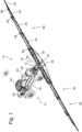
- FIG Figures 1 to 3 out An embodiment variant of an agricultural distribution machine 10 according to the invention is shown in FIG Figures 1 to 3 out.
- the distribution machine 10 shown here is designed as a self-propelled machine, and the invention can also be used or used in towed or autonomous machines.
- the distribution machine 10 comprises four wheels 12 carrying the distribution machine 10, with two opposing wheels 12 each forming a chassis or an axle and with at least the wheels 12 of the front axle 14 or only the wheels 12 of the rear axle 16 or the wheels 12 of both axles 14; 16 are each arranged, for example, to be pivotable or steerable about upright axes to the frame 18.
- the axes 14; 16 are also mounted on a frame 18 carrying the components of the distribution machine 10.
- the distribution machine 10 includes a motor 20 driving the distribution machine 10, a cabin 22 and a storage container 24 for carrying and providing the respective liquid and/or the granular or granular substances or their mixtures.
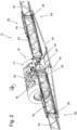
- the frame 18 is assigned a parallelogram 26 whose height can be adjusted in relation to the frame 18 by means of actuators.
- a distribution device 30 extending transversely to the direction of travel 28 is connected.
- the embodiment using a parallelogram 26 only represents one option for mounting the distribution device 30. It would also be conceivable to attach this directly to the frame 18.
- the attachment of the distribution device 30 will be referred to in each case in the following in relation to the frame, although this does not exclude a connection by means of a parallelogram 26 or another intermediate segment or intermediate frame, but rather the term frame is used in conjunction with the attachment of the distribution device 30 also refers to such embodiments.
- the distribution device is divided into several linkage segments 32 and consists of a middle part 34 and side parts 38 which are pivotally attached to the left and right of this via upright axes 36, the side parts 38 in turn being composed of several rod segments 32 which are also arranged pivotably relative to one another by means of upright axes 36 .
- the distribution machine 10 shown is composed, for example, of a total of eleven linkage segments 32, each of which can be pivoted relative to one another about upright axes 36.
- the distribution device 30 or its middle part 34 could also be attached to the frame 18 or to the parallelogram 26 so that it can pivot about an upright axis, as a result of which the entire distribution device 30 could also be pivoted accordingly.
- motor actuators 40 are provided on these, which are controlled or actuated in particular by an electronic control device 42 (cf. Fig. 6 ).
- an electronic control device 42 cf. Fig. 6
- actuators 40 according to Figures 1 to 3 These are hydraulically operated cylinders or linear drives, which are controlled by an electrically operated valve.
- pneumatic and/or electrically operated actuators 40 could also be used.
- the yaw and pitching movements acting on the distribution device 30 (cf. Fig. 3 Arrows), which can be detected by sensors, for example, by appropriately controlling the Actuators 40 are counteracted.
- the motorized actuators 40 can also be provided with damping means or the like in order to counteract corresponding yaw and pitch movements.
- the distribution device 30 can be pivoted about an axis of rotation 44 running in the direction of travel 28 by means of at least one drive unit 72 in accordance with a ground contour, in order to achieve the most exact adaptation possible to the respective ground contour or the respective horizon, or to achieve the same distances as possible between the distribution device 30 and the ground contour or to a plant population.
- the agricultural distribution machine 10 shown here is designed as an agricultural distribution machine 10 towed by a towing vehicle 46, whereby it should again be noted that the invention can also be used or used in self-propelled or autonomous machines.
- the distribution machine 10 is moved over a field 48 by means of a towing vehicle 46, the field 48 having an edge structure 50 composed of several sides, which edge structure 50 also contains several corners 52 with different angles to one another.
- the connection between the distribution machine 10 and the towing vehicle takes place by means of a towing device or a drawbar 54. Edge structures which have curves or edge structures which have corners 52 and curves would also be conceivable.
- the distribution machine 10 also has an axle or a chassis with two steerable wheels 12, which wheels 12 can be pivoted or steered by means of a motorized actuator. It should be noted that in addition to steering the wheels 12, it would also be conceivable to steer the distribution machine 10 by means of a pivotable pulling device 54 or to steer the distribution machine 10 both by means of the wheels 12 and by means of the pulling device 54.
- the agricultural distribution machine 10 is guided along lanes 56 by means of the towing vehicle 46.
- the lanes 56 can be so-called tramlines, for example.
- lanes 56 would also be conceivable, in particular the respective lanes 56 can be detected and/or evaluated by means of lane detection devices 74, for example these could also be stored in the control device 42 or corresponding data could be retrieved from a database using the control device 42 .
- the respective edge structure 50 is determined by means of various contour determination devices 58, such as a laser scanner and/or a camera and/or by means of a GPS system and / or by means of radar sensors or the like and is transmitted accordingly to the control device 42 or are attached to the distribution machine 10 or are connected to the control device 42.
- the respective edge structures 50 can also be retrieved or read out from a database using the control device 42.
- sensors 60 are attached to the distribution device 30 and/or to the respective linkage segments 32 and/or to the respective steerable wheels 12 and/or the steerable drawbar 54 and/or the actuators or to the upright axles in such a way that by means of them the current orientation or relative position 62 is determined.
- the control device 42 an orientation of the distribution device 30 or an orientation of its linkage segments 32 with respect to the edge structure 50 can be calculated using a corresponding control program and then the respective motorized actuator 40 or a valve 64 assigned to it can be controlled accordingly and thus the distribution machine 10 or its distribution device 30 or its linkage segments 32 are moved into a desired position.
- the respective motorized actuator 40 is controlled accordingly on the basis of the control program and the distribution device 30 and/or the linkage segments 32 are pivoted accordingly.
- the distribution machine 10 can also be steered accordingly by means of the drawbar 54 or by means of the wheels 12 in order to achieve an at least largely parallel and/or perpendicular alignment to the existing edge structure 50 by means of the distribution device 30 or by means of the linkage segments 32.
- the distribution machine 10 could also be steered accordingly and the distribution device 30 and/or the linkage segments 32 could be pivoted accordingly.
- the entire distribution device 30 is pivoted in such a way that it has an at least largely parallel orientation to the edge structure 50
- the distribution machine 10 can each be guided along a definable or a defined lane 56, which means that its wheels 12 and/or its pulling device 54 are steered in such a way that they follow the lane 56.
- lane detection devices 74 can be assigned to the distribution machine 10 and/or connected to a control device 42.
- the actuators could also be controlled in such a way that the distribution machine 10 follows the lanes 56, while the distribution device 30 or its linkage segments 32 are pivoted accordingly based on the existing edge structure 10, so that the distribution device 30 or its linkage segments 32 of the edge structure follow 50 parallel or perpendicular.
- contour determination devices 58 connected to the distribution machine 10 or to the control device 42 are provided.
- the contour determination devices 58 can detect and/or evaluate the respective edge structure 50 accordingly and transmit it to the control device 42.
- the contour determination devices 58 could also only transmit signals to the control device 42.
- An edge structure 50 could then be generated or evaluated accordingly using a control program stored in the control device 42.
- the contour determination device 58 could also be a database or could be connected to a database.
- sensors 60 are provided, for example on the distribution machine 10 and/or on the upright axles and/or the actuators .
- the sensors 60 can in particular be any type of position sensors, for example angle potentiometers or angle sensors or the like.
- the sensors 60 can detect the respective relative position 62 accordingly and send it to the control device 42 to transfer.
- the sensors 60 could also only transmit signals to the control device 42. The corresponding signals can then be converted into corresponding values of the relative positions 62 using a control program stored in the control device 42.
- control device 42 In addition to the edge structure 50 and the relative position 62, further information can be entered into the control device 42 or processed by it. It would be conceivable for a wide variety of parameters 76, such as the current driving movements 68, to be recorded using additional measuring devices 66. During the driving movements 68, it can be recorded, for example, whether the distribution machine 10 or its towing vehicle 46 is moving forwards or backwards or at what speed the distribution machine 10 or its towing vehicle 46 is moving. It could also be recorded whether the distribution machine 10 or its towing vehicle 46 is accelerated or decelerated.
- parameters 76 such as the current driving movements 68
- the lanes 56 could also be recorded and evaluated using additional measuring devices 66 or lane detection devices 74. However, the lanes 56 could also be transmitted to the control device 42 using a GPS system. Likewise, the lanes 56 could be stored in a database connected to the control device 42.
- further measuring means 66 could be provided for determining the orientation of the distribution machine 10, for example acceleration sensors or rotation rate sensors or gyroscopes or position sensors or the like.
- a valve 64 associated with the respective motorized actuator 40 is then controlled by means of the control device 42, which then controls the actuator 40 in such a way that the distribution device 30 or the linkage segments 32 or the distribution machine 10 take the desired position.
- a further control unit 70 and a drive unit 72 of the distribution machine 10 are controlled and thus the travel movements of the distribution machine 10 are in turn controlled accordingly depending on the relative position 62 and the edge structure 50 and, for example, also the lanes 56 or be regulated.
- a further control unit 70 and a drive unit 72 of the distribution machine 10 are controlled and thus the travel movements of the distribution machine 10 are in turn controlled accordingly depending on the relative position 62 and the edge structure 50 and, for example, also the lanes 56 or be regulated.
- both its distribution device 10 and Their driving movements are also carried out largely autonomously and without the intervention of an operator.
- a control program is stored in the control device 42, which, taking into account the recorded actual values of the alignment or the relative position and the detected or existing edge structure 50, carries out a calculation
- Control of the motorized actuator 40 is created, and corresponding travel speeds of the actuator 40 can also be defined using the control program.
- the travel speeds could also be further specified taking into account and processing various parameters 76, such as current travel movements 68 of the distribution machine 10, i.e. the greater the travel speed of the distribution machine 10, the faster the travel speed of the at least one motorized actuator 40.
- the travel speeds could also be based on various other parameters 76, so that double treatments and/or under-treatments can be avoided by pivoting too quickly or too slowly.
- the travel speed can be based on the travel speed of the distribution machine 10 and/or on the basis of the application rate and/or on the basis of the distance traveled and/or on the basis of the relative positions detected in each case.
- These parameters 76 can also be recorded, for example, using a wide variety of measuring devices 66 and processed using the control program stored in the control device 42.
Description
Die vorliegende Erfindung betrifft eine landwirtschaftliche Verteilmaschine zum Ausbringen von Flüssigkeiten und/oder körnigen oder granulierten Stoffen mit den Merkmalen des Oberbegriffs des unabhängigen Anspruchs 1. Die Erfindung betrifft zudem ein Verfahren zur Steuerung und/oder Regelung einer Verteilmaschine mit den Merkmalen des Oberbegriffs des unabhängigen Verfahrensanspruchs 11.The present invention relates to an agricultural distribution machine for dispensing liquids and/or granular or granulated substances with the features of the preamble of
In der Landwirtschaft finden verschiedenste Ausführungsformen von Verteilmaschinen zum Ausbringen von unterschiedlichsten Wirkstoffen wie Flüssigkeiten und/oder körnigen oder granulierten Stoffen Verwendung. Häufig werden derartige landwirtschaftliche Verteilmaschinen auch als Feldspritzen bezeichnet. Zur Verteilung der jeweiligen Wirkstoffe besitzen die Verteilmaschinen in der Regel eine sich in Arbeitsposition quer zur Fahrtrichtung erstreckende Verteilvorrichtung. Die Verteilmaschinen können sowohl als selbstfahrende oder auch als an einem Zugfahrzeug angehängte oder angebaute Verteilmaschinen ausgebildet sein. Zudem gibt es darüber hinaus bereits erste Lösungsansätze um derartige Verteilmaschinen auch als autonome Fahrzeuge bzw. Verteilmaschinen zu bauen. Die Verteilvorrichtungen bzw. die auch als Spritzgestänge bezeichneten Verteilvorrichtungen weisen mitunter große Arbeitsbreiten von zwanzig Meter und mehr auf, wobei derartige Verteilvorrichtungen zumeist in mehrere Gestängesegmente unterteilt sind, die jeweils um aufrechte Achsen schwenkbar zueinander angeordnet sind und somit, u.a. für eine Transportfahrt, um diese aufrechte Achsen in eine für die Transportfahrt maximal zulässige Transportbreite zusammengeklappt werden können.In agriculture, a wide variety of embodiments of distribution machines are used for dispensing a wide variety of active ingredients such as liquids and/or granular or granular substances. Such agricultural distribution machines are often also referred to as field sprayers. To distribute the respective active ingredients, the distribution machines usually have a distribution device that extends transversely to the direction of travel in the working position. The distribution machines can be designed as self-propelled distribution machines or as distribution machines attached or attached to a towing vehicle. In addition, there are already initial approaches to building such distribution machines as autonomous vehicles or distribution machines. The distribution devices or the distribution devices, also known as spray booms, sometimes have large working widths of twenty meters or more, with such distribution devices usually being divided into several boom segments, each of which is arranged to be pivotable relative to one another about upright axes and thus, among other things, for a transport journey upright axles can be folded into a maximum permissible transport width for the transport journey.
Eine derartige Verteilmaschine geht bspw. aus der
Vergleichbare Systeme gehen aus der
Ein Verfahren zur Korrektur von in einem Speicher eines Arbeitsrechners einer landwirtschaftlichen Verteilmaschine gespeicherter, bspw. mittels eines GPS-Systems aufgezeichneter Positionskoordinaten geht aus der
Aus der
Eine Verteilmaschine mit einem verbesserten System zur Teilbreitensteuerung geht aus der
Darüber hinaus zeigt die
Weitere landwirtschaftliche Verteilmaschinen sind aus der
Somit sind aus dem Stand der Technik verschiedenste Systeme bekannt, um insbesondere die Dämpfungseigenschaften einer Verteilvorrichtung zu beeinflussen, sowie um eine Verteilvorrichtung um eine aufrechte Achse zu verschwenken. Auch ist es bekannt verschiedenste Fahrspuren zu definieren, entlang derer die Verteilmaschinen jeweils geführt werden. Um jedoch eine exakte Bearbeitung bzw. Behandlung einer Ackerfläche zu gewährleisten, ist es auch erforderlich, die Ecken und Spitzen oder Kurven oder dergl. exakt zu bearbeiten, d.h. dass die komplette Ackerfläche bearbeitet wird und keine Fehlstellen bzw. sog. Spritzfenster vorhanden sind, da an unbehandelten Flächen Unkräuter wachsen können, welche sich wiederum entsprechend vermehren und zudem überbehandelte Flächen Resistenzen erzeugen können. Dies ist jedoch insbesondere bei Verteilmaschinen mit Verteilvorrichtungen mit einer großen Arbeitsbreite von 20 Meter und mehr nicht ohne weiteres möglich, da es bislang erforderlich war, die jeweiligen Ecken durch eine Rückwärtsfahrt auszufahren und anschließend diese zu bearbeiten bzw. zu behandeln oder einzelne Gestängesegmente einzuklappen. Da jedoch bei großen Arbeitsbreiten bereits geringste Lenkwinkelveränderungen zu großen Auslenkungen der Verteilvorrichtung führen, ist dies nicht immer ohne weiteres möglich, insbesondere wenn es sich um keine rechtwinkligen Ecken handelt, sondern um stumpfe oder spitze Winkel aufweisende Ecken. Um diese exakt zu bearbeiten bzw. zu behandeln, kommt es immer wieder vor, dass durch das jeweilige Rangieren bei der Rückwärtsfahrt der Pflanzenbestand beschädigt wird bzw. viele Pflanzen überfahren werden. Insbesondere ist für das jeweilige Rangieren auch ein großes fahrerisches Geschick einer Bedienperson erforderlich. Auch besteht ein weiteres Problem bei den aus dem Stand der Technik bekannt gewordenen Verteilmaschinen darin, dass diese, wenn sie entlang einer Fahrspur geführt werden, die Ränder der Ackerfläche nicht mehr exakt bearbeiten können, da die Verteilvorrichtung jeweils auf Basis der Ausrichtung der Verteilmaschine verschwenkt wird, wobei die Ausrichtung der Verteilmaschine jedoch abweichend zu einer Randstruktur der Ackerfläche ist.A wide variety of systems are therefore known from the prior art, in particular to influence the damping properties of a distribution device, as well as to pivot a distribution device about an upright axis. It is also known to define various lanes along which the distribution machines are guided. However, in order to ensure precise processing or treatment of a field, it is also necessary to process the corners and points or curves or the like precisely, that is, that the entire field is processed and there are no defects or so-called spray windows Weeds can grow on untreated areas, which in turn multiply accordingly and over-treated areas can also generate resistance. However, this is not easily possible, especially in distribution machines with distribution devices with a large working width of 20 meters or more, since it was previously necessary to extend the respective corners by reversing and then to process or treat them or to fold in individual boom segments. However, since even the slightest changes in the steering angle lead to large deflections of the distribution device with large working widths, this is not always easily possible, especially if the corners are not right-angled, but rather corners with obtuse or acute angles. In order to process or treat these precisely, it often happens that the plant population is damaged or many plants are run over as a result of maneuvering when reversing. In particular, the operator also requires great driving skills for the respective maneuvering. There is also a further problem with the distribution machines known from the prior art that when they run along a Lane are guided, the edges of the arable land can no longer be processed precisely, since the distribution device is pivoted based on the orientation of the distribution machine, although the orientation of the distribution machine is different from an edge structure of the arable land.
Der Erfindung liegt somit die Aufgabe zugrunde eine landwirtschaftliche Verteilmaschine mit einer Verteilvorrichtung mit großer Arbeitsbreite sowie ein Verfahren zur Steuerung diese Verteilmaschine zu schaffen, mit der es vereinfacht wird, auch stumpfe oder spitze oder rechte Winkel aufweisende Ecken und kurvenreiche Grenzen bzw. Randstrukturen einer Ackerfläche zu bearbeiten bzw. zu behandeln, ohne hierbei den Pflanzenbestand zu beschädigen und gleichzeitig Doppelbehandlungen weitgehend zu vermeiden.The invention is therefore based on the object of creating an agricultural distribution machine with a distribution device with a large working width and a method for controlling this distribution machine, with which it is simplified to also create obtuse or acute or right-angled corners and curved boundaries or edge structures of a field to process or treat without damaging the plant population and at the same time largely avoid double treatments.
Diese Aufgaben der Erfindung werden durch eine landwirtschaftliche Verteilmaschine zum Ausbringen von Flüssigkeiten und/oder körnigen oder granulierten Stoffen mit den Merkmalen des Anspruchs 1 sowie durch ein Verfahren zur Steuerung und Regelung einer Verteilmaschine mit den Merkmalen im Verfahrensanspruch 11 gelöst. Weitere vorteilhafte Ausgestaltungen und Weiterbildungen der Erfindung sind in den jeweiligen abhängigen Ansprüchen angegeben.These objects of the invention are achieved by an agricultural distribution machine for dispensing liquids and / or granular or granulated substances with the features of
Zur Lösung der genannten Aufgaben schlägt die Erfindung eine landwirtschaftliche Verteilmaschine vor.To solve the tasks mentioned, the invention proposes an agricultural distribution machine.
Die landwirtschaftliche Verteilmaschine weist zumindest einen Rahmen und einen oder mehrere Vorratsbehälter auf. Am Rahmen befindet sich eine beweglich angeordneten Verteilvorrichtung zum Ausbringen von Flüssigkeiten und/oder körnigen oder granulierten Stoffen. Die landwirtschaftliche Verteilmaschine weist weiterhin ein wenigstens zwei Räder aufweisendes Fahrwerk und/oder einer Zugvorrichtung auf, wobei die Räder und/oder die Zugvorrichtung über aufrechte Achsen schwenkbar bzw. lenkbar am Rahmen oder gegenüber dem Rahmen lenkbar bzw. schwenkbar angeordnet sind.The agricultural distribution machine has at least one frame and one or more storage containers. There is a movably arranged distribution device on the frame for dispensing liquids and/or granular or granular substances. The agricultural distribution machine further has a chassis having at least two wheels and/or a towing device, wherein the wheels and/or the towing device are arranged to be pivotable or steerable on the frame or to be steerable or pivotable relative to the frame via upright axles.
Zum Verschwenken bzw. zum Lenken der Räder und/oder der Zugvorrichtung ist zumindest ein von einer elektronischen Regeleinrichtung ansteuerbares motorisches Stellglied vorgesehen ist. Dem Fahrwerk und/oder den aufrechten Achsen und/oder dem zumindest einen zum Verschwenken bzw. zum Lenken der Räder und/oder der Zugvorrichtung vorgesehenen Stellglied sind Sensoren zur Erfassung und Weiterleitung eines Istwertes bzgl. der Ausrichtung des Fahrwerks zugeordnet, wobei zur Erfassung und Auswertung einer Randstruktur einer von der landwirtschaftlichen Verteilmaschine zu bearbeitenden und/oder zu überfahrenden Fläche Konturermittlungseinrichtungen vorgesehen sind, welche der Verteilmaschine zugeordnet sind und mit der Regeleinrichtung in Verbindung stehen. Hierbei erfolgt eine Ansteuerung des zumindest einen zum Verschwenken bzw. zum Lenken der Räder und/oder der Zugvorrichtung vorgesehenen Stellgliedes in Abhängigkeit von einer erfassten Ausrichtung der Räder und/oder der Zugvorrichtung und von einer vorhandenen bzw. erfassten Randstruktur.For pivoting or steering the wheels and/or the pulling device, at least one motorized actuator that can be controlled by an electronic control device is provided. The chassis and/or the upright axles and/or the at least one actuator provided for pivoting or steering the wheels and/or the towing device are assigned sensors for detecting and forwarding an actual value regarding the alignment of the chassis, for detection and evaluation an edge structure of one of the agricultural distribution machine contour determination devices are provided for the surface to be processed and/or driven over, which are assigned to the distribution machine and are connected to the control device. Here, the at least one actuator provided for pivoting or steering the wheels and/or the towing device is controlled depending on a detected orientation of the wheels and/or the towing device and on an existing or detected edge structure.
Erfindungsgemäß ist vorgesehen, dass eine Randstruktur anhand eines mit einem Gyroskop ermittelten Kurvenradius mittels eines in der Regeleinrichtung hinterlegten Steuerungsprogramms berechnet wird.According to the invention, it is provided that an edge structure is calculated based on a curve radius determined with a gyroscope using a control program stored in the control device.
Die landwirtschaftliche Verteilmaschine kann hierbei als selbstfahrende oder als mittel Zugfahrzeug gezogene oder als eine an einem Zugfahrzeug angebaute Verteilmaschine ausgeführt sein. Bei einer mittels Zugmaschine oder Zugfahrzeug gezogenen Ausführung der landwirtschaftlichen Verteilmaschine kann die Verbindung zwischen der Verteilmaschine und dem Zugfahrzeug insbesondere mittels einer an sich bekannten Zugvorrichtung bzw. einer Zugdeichsel erfolgen. Auch kann die Verteilmaschine als ein autonomes Fahrzeug ausgeführt sein, bzw. eine autonome Verteilmaschine mit Verteilvorrichtung sein. Die Verteilmaschine umfasst zumindest einen Rahmen zum Tragen der jeweiligen Komponenten, einen oder mehrere Vorratsbehälter zum Mitführen und Bereitstellen des jeweiligen Verteilguts sowie eine sich in einer Arbeitsposition quer zur Fahrtrichtung erstreckende Verteilvorrichtung, an welcher Verteilvorrichtung nach unten gerichtete Ausbringdüsen zum Ausbringen und Verteilen der jeweiligen Flüssigkeiten und/oder der körnigen oder granulierten Stoffe angebracht sind.The agricultural distribution machine can be designed as a self-propelled distribution machine or as a distribution machine towed by a towing vehicle or as a distribution machine attached to a towing vehicle. In an embodiment of the agricultural distribution machine towed by a tractor or towing vehicle, the connection between the distribution machine and the towing vehicle can be carried out in particular by means of a known towing device or a drawbar. The distribution machine can also be designed as an autonomous vehicle or an autonomous distribution machine with a distribution device. The distribution machine comprises at least one frame for carrying the respective components, one or more storage containers for carrying and providing the respective goods to be distributed, and a distribution device which extends transversely to the direction of travel in a working position, on which distribution device downward-directed dispensing nozzles for dispensing and distributing the respective liquids and /or the granular or granular substances are appropriate.
Die Verteilvorrichtung ist beweglich am Rahmen angeordnet, wobei die Verteilvorrichtung hierfür bspw. mittels eines Parallelogramms oder mittels eines Linearschlittens auch in dessen Höhe verstellbar zum Rahmen angebracht, aber auch direkt am Rahmen angebaut sein kann. Zum besseren Verständnis wird im nachfolgenden die Anbringung der Verteilvorrichtung jeweils nur auf den Rahmen bezogen, wobei dadurch jedoch eine Verbindung bspw. mittels eines Parallelogramms oder dergl. Zwischenrahmen zwischen der Verteilvorrichtung und dem Rahmen nicht ausgeschlossen ist, sondern sich die Bezeichnung Rahmen gleichermaßen auch auf derartige Ausführungsformen bezieht bzw. derartige Ausführungsformen beinhaltet, d.h. bei Anbringung der Verteilvorrichtung auf den bzw. am Rahmen kann eine Verbindung mittels eines Parallelogramms oder eines anderen Zwischensegments oder Zwischenrahmens nicht ausgeschlossen sein.The distribution device is movably arranged on the frame, the distribution device being attached to the frame in such a way that its height can be adjusted, for example by means of a parallelogram or by means of a linear slide, but can also be mounted directly on the frame. For better understanding, the attachment of the distribution device will only be referred to the frame below, although this does not exclude a connection, for example by means of a parallelogram or similar intermediate frame, between the distribution device and the frame, but the term frame also applies to such Embodiments refers or includes such embodiments, ie when attaching the distribution device to or on the frame, a connection can be made cannot be excluded by means of a parallelogram or other intermediate segment or intermediate frame.
Zudem kann die Verteilvorrichtung in mehrere Gestängesegmente unterteilt sein, bspw. in ein Mittelteil und zwei, vorzugsweise links und rechts vom Mittelteil befindliche, über aufrechte Achsen schwenkbar an diesem angebaute Seitenteile, wobei auch wiederum die Seitenteile aus mehreren ebenfalls mittels aufrechter Achsen schwenkbar zueinander angeordneter Gestängesegmente zusammengesetzt sein können. Beispielsweise kann sich ein Verteilergestänge einer Verteilmaschine aus z.B. insgesamt elf Gestängesegmenten zusammensetzen, welche jeweils um aufrechte Achsen zueinander verschwenkbar sind. Es wäre allerdings auch jegliche weitere Anzahl an gelenkig miteinander verbundenen Gestängesegmenten denkbar.In addition, the distribution device can be divided into several linkage segments, for example into a middle part and two side parts, preferably located to the left and right of the middle part, which are pivotally attached to it via upright axes, the side parts again being made up of several rod segments which are also arranged to be pivotable relative to one another by means of upright axes can be composed. For example, a distributor linkage of a distribution machine can be composed of, for example, a total of eleven linkage segments, each of which can be pivoted relative to one another about upright axes. However, any other number of linkage segments connected to one another in an articulated manner would also be conceivable.
Zudem kann auch die Verteilvorrichtung bzw. dessen Mittelteil um eine aufrechte Achse schwenkbar am Rahmen bzw. an einem dem Rahmen zugeordneten Parallelogramm oder Linearschlitten oder dergleichen angebracht sein, d.h. dass dadurch die gesamte Verteilvorrichtung entsprechend verschwenkt werden könnte. Das Verschwenken der jeweiligen Gestängesegmente bzw. der Verteilvorrichtung um die aufrechten Achsen erfolgt mittels zumindest eines von einer elektronischen Regeleinrichtung ansteuerbaren motorischen Stellglieds. Zudem sind den Gestängesegmenten und/oder den aufrechten Achsen und/oder dem zumindest einen motorischen Stellglied Sensoren derartig zugeordnet, dass diese einen Istwert bzgl. der vorhandenen Ausrichtung bzw. der aktuellen Relativposition erfassen und an eine Regeleinrichtung weiterleiten bzw. ausgeben können.In addition, the distribution device or its middle part can also be attached to the frame or to a parallelogram or linear slide or the like assigned to the frame so that it can pivot about an upright axis, i.e. that the entire distribution device could be pivoted accordingly. The respective linkage segments or the distribution device are pivoted about the upright axes by means of at least one motor actuator that can be controlled by an electronic control device. In addition, the linkage segments and/or the upright axes and/or the at least one motorized actuator are assigned sensors in such a way that they can detect an actual value with regard to the existing orientation or the current relative position and forward or output it to a control device.
Vorzugsweise kann die Verteilvorrichtung um eine in Fahrtrichtung verlaufende Drehachse mittels zumindest eines Antriebselements entsprechend einer Bodenkontur verschwenkt werden, um somit eine möglichst exakte Anpassung an die jeweilige Bodenkontur bzw. den jeweiligen Horizont zu erreichen bzw. um möglichst gleiche Abstände zwischen der Verteilvorrichtung und der Bodenkontur bzw. zu einem Pflanzenbestand zu erreichen.Preferably, the distribution device can be pivoted about an axis of rotation running in the direction of travel by means of at least one drive element in accordance with a floor contour, in order to achieve the most exact possible adaptation to the respective floor contour or the respective horizon or to achieve the same distances as possible between the distribution device and the floor contour or .to reach a plant population.
Zudem kann die Verteilmaschine in einer Ausführungsvariante zumindest ein aus wenigstens zwei Rädern gebildetes Fahrwerk bzw. eine oder mehrere lenkbare Achsen aufweisen, wobei die Räder wiederum über aufrechte Achsen schwenkbar bzw. lenkbar zum Rahmen angeordnet sein können, und wobei zur Lenkung wiederum zumindest ein von einer elektronischen Regeleinrichtung ansteuerbares motorisches Stellglied vorgesehen sein kann. Zudem können dem Fahrwerk und/oder den aufrechten Achsen und/oder dem zumindest einen Stellglied Sensoren derartig zugeordnet sein, dass diese einen Istwert bzgl. der vorhandenen Ausrichtung bzw. der aktuellen Relativposition Erfassen und an eine Regeleinrichtung weiterleiten bzw. ausgeben können.In addition, in one embodiment variant, the distribution machine can have at least one chassis formed from at least two wheels or one or more steerable axles, wherein the wheels can in turn be arranged to be pivotable or steerable to the frame via upright axles, and in turn at least one of one for steering Electronic control device controllable motor actuator can be provided. In addition, sensors can be assigned to the chassis and/or the upright axles and/or the at least one actuator in such a way that they can detect an actual value with regard to the existing orientation or the current relative position and forward or output it to a control device.
Wahlweise kann die landwirtschaftliche Verteilmaschine vier Räder umfassen, wobei jeweils zwei gegenüberliegende Räder ein Fahrwerk bzw. eine Achse bilden und wobei zumindest die Räder der vorderen Achse oder nur die Räder der hinteren Achse oder die Räder beider Achsen jeweils bspw. um aufrechte Achsen schwenkbar bzw. lenkbar zum Rahmen angeordnet sind. Die Achsen können zudem an einem die Komponenten der Verteilmaschine tragenden Rahmen montiert sein. Zudem kann die Verteilmaschine einen die Verteilmaschine antreibenden Motor und eine Kabine umfassen.The agricultural distribution machine can optionally comprise four wheels, with two opposite wheels forming a chassis or an axle and with at least the wheels of the front axle or only the wheels of the rear axle or the wheels of both axles each being pivotable about upright axes, for example. are arranged to be steerable to the frame. The axles can also be mounted on a frame that supports the components of the distribution machine. In addition, the distribution machine can include a motor driving the distribution machine and a cabin.
Auch könnte bei einer Ausführungsvariante der landwirtschaftlichen Verteilmaschine als mittels eines Zugfahrzeuges gezogene Verteilmaschine, diese zur Verbindung mit dem Zugfahrzeug eine Zugvorrichtung aufweisen, wobei auch wiederum die Zugvorrichtung um eine aufrechte Achse schwenkbar bzw. lenkbar zum Rahmen angebracht sein kann und ebenso wiederum mittels eines motorischen Stellgliedes eine Position bzw. Ausrichtung der Zugvorrichtung in Bezug auf den Rahmen verändert werden kann, um somit die Verteilmaschine zu lenken.In an embodiment variant of the agricultural distribution machine as a distribution machine towed by a towing vehicle, it could also have a towing device for connection to the towing vehicle, in which case the towing device can also be attached to the frame in such a way that it can be pivoted or steered about an upright axis and also by means of a motorized actuator a position or orientation of the pulling device can be changed in relation to the frame in order to steer the distribution machine.
Um eine landwirtschaftliche Verteilmaschine mit einer Verteilvorrichtung mit großer Arbeitsbreite zu schaffen, mit der es vereinfacht bzw. ermöglicht wird auch stumpfe oder spitze oder rechte Winkel aufweisende Ecken und kurvenreiche Grenzen bzw. Randbereiche einer Ackerfläche zu bearbeiten bzw. zu behandeln ohne hierbei den Pflanzenbestand zu beschädigen sowie um Doppelbehandlungen weitgehend zu vermeiden, ist vorgesehen, dass zur Erfassung und/oder Auswertung einer vorhandenen Randstruktur der Verteilmaschine zugeordneten und/oder mit einer Regeleinrichtung dieser in Verbindung stehenden Konturermittlungseinrichtungen vorgesehen sind und dass eine Ansteuerung des zumindest einen motorischen Stellglieds zur Lenkung und/oder zum Verschwenken der Zugvorrichtung und/oder der Räder in Abhängigkeit einer erfassten aktuellen Ausrichtung bzw. Relativposition der Räder und/oder der Zugvorrichtung und der jeweils vorhandenen bzw. erfassten Randstruktur erfolgt.In order to create an agricultural distribution machine with a distribution device with a large working width, with which it is simplified or possible to process or treat blunt or acute or right angle corners and curved boundaries or edge areas of a field without damaging the crop and in order to largely avoid double treatments, it is provided that for detecting and / or evaluating an existing edge structure of the distribution machine and / or connected to a control device of this contour determination devices are provided and that a control of the at least one motorized actuator for steering and / or for pivoting the towing device and/or the wheels depending on a detected current orientation or relative position of the wheels and/or the towing device and the respective existing or detected edge structure.
Um dies noch weiter zu verbessern kann, vorgesehen sein, dass zur Erfassung und/oder Auswertung einer vorhandenen Randstruktur, der Verteilmaschine zugeordneten und/oder mit einer Regeleinrichtung dieser in Verbindung stehenden Konturermittlungseinrichtungen vorgesehen sind und dass eine Ansteuerung des zumindest einen motorischen Stellglieds zur Verschwenkung der Gestängesegmente und/oder der Verteilvorrichtung in Abhängigkeit einer erfassten aktuellen Ausrichtung bzw. Relativposition der Gestängesegmente und/oder der Verteilvorrichtung und der jeweils vorhandenen bzw. erfassten Randstruktur erfolgt.In order to improve this even further, provision can be made for the detection and/or evaluation of an existing edge structure assigned to the distribution machine and / or with a control device of these connected contour determination devices are provided and that a control of the at least one motorized actuator for pivoting the linkage segments and / or the distribution device depending on a detected current orientation or relative position of the linkage segments and / or the distribution device and the respective existing or detected edge structure takes place.
Durch die Verteilmaschine bzw. durch deren Lenkung kann weiterhin mittels des Stellgliedes die Verteilmaschine und die an dieser angebrachte Verteilvorrichtung bzw. deren Gestängesegmente derartig bewegt werden, dass diese eine zumindest weitgehend parallele oder rechtwinkelige Ausrichtung zur erfassten bzw. vorhandenen Randstruktur aufweisen, wodurch vorhandene Ecken bzw. Randstrukturen mit verschiedensten Winkel und kurvenreiche Feldgrenzen entsprechend ganzflächig behandelt werden können und zudem Doppelbehandlungen weitgehend vermieden werden können.By means of the distribution machine or its steering, the distribution machine and the distribution device attached to it or its linkage segments can also be moved by means of the actuator in such a way that they have an at least largely parallel or perpendicular orientation to the detected or existing edge structure, whereby existing corners or Edge structures with a wide range of angles and curved field boundaries can be treated over the entire surface and double treatments can be largely avoided.
Es sei darauf hingewiesen, dass der Begriff rechtwinkelig bei einer eine Kurve aufweisenden Randstruktur derartig zu verstehen sein kann, dass die Verteilvorrichtung bzw. deren Gestängesegmente der Kurve jeweils zumindest annähernd oder exakt im Lot der Kurve folgen können.It should be noted that the term right-angled in the case of an edge structure having a curve can be understood in such a way that the distribution device or its linkage segments can follow the curve at least approximately or exactly perpendicular to the curve.
Bei den Sensoren zur Erfassung der jeweiligen Ausrichtung bzw. der jeweiligen Relativposition kann es sich insbesondere um Winkelpotentiometer oder Winkelsensoren oder Positionssensoren oder dergl. Sensoren handeln. Auch Linearmesssysteme wären denkbar bzw. einsetzbar. Generell wären somit jegliche Sensoren denkbar mittels denen eine aktuelle Ausrichtung erfasst bzw. ermittelt werden kann. Mittels der Sensoren wird somit bspw. ein Lenkwinkel der Räder und/oder der Zugvorrichtung in Bezug auf den Rahmen erfasst und ausgewertet. Zudem kann mittels der Sensoren auch eine Position der Verteilvorrichtung in Bezug auf den Rahmen ermittelt werden. Die von den Sensoren erfassten Signale können entsprechend an die Regelungseinrichtung übermittelt werden, wobei die Signale anschließend mittels eines in der Regeleinrichtung hinterlegten Steuerungsprogramms in entsprechende Werte der Relativpositionen umgewandelt werden.The sensors for detecting the respective orientation or the respective relative position can in particular be angle potentiometers or angle sensors or position sensors or similar sensors. Linear measuring systems would also be conceivable or usable. In general, any sensors would be conceivable by means of which a current orientation can be detected or determined. Using the sensors, for example, a steering angle of the wheels and/or the towing device in relation to the frame is recorded and evaluated. In addition, a position of the distribution device in relation to the frame can also be determined using the sensors. The signals detected by the sensors can be transmitted accordingly to the control device, with the signals then being converted into corresponding values of the relative positions using a control program stored in the control device.
Die Verteilmaschine kann jeweils entlang einer definierbaren bzw. einer definierten Fahrspur geführt werden; d.h. dass bspw. die Räder oder die Zugvorrichtung bzw. die Verteilmaschine derartig gelenkt wird/werden, dass diese einer Fahrspur folgt/folgen, wodurch wiederum ein Überfahren von Pflanzen verhindert bzw. verringert werden kann. So können zur Erfassung und/oder Auswertung einer Fahrspur der Verteilmaschine zugeordnet und/oder mit einer Regeleinrichtung in Verbindung stehend Spurermittlungseinrichtungen vorgesehen sein. Als Fahrspuren können bspw. sog. Fahrgassen verwendet werden, welche mittels zusätzlicher Messmittel erfasst werden können oder deren Daten in der Regeleinrichtung hinterlegt sein können. Auch könnten als Spurermittlungseinrichtungen ein Laserscanner und/oder eine Kamera bzw. ein Kamerasystem und/oder ein Radarsensor vorgesehen sein. Ebenso könnte zur Spurermittlung ein GPS-System an der Verteilmaschine vorgesehen sein. Ebenso wäre es denkbar, dass die jeweiligen Fahrspuren aus einer Datenbank ausgelesen werden oder dass die Fahrspur anhand eines ermittelten Kurvenradius mittels eines in der Regeleinrichtung hinterlegten Steuerungsprogramms berechnet wird.The distribution machine can be guided along a definable or defined lane; that is, for example, the wheels or the towing device or the distribution machine is/are steered in such a way that they follow/follow a lane, which in turn can prevent or reduce running over plants. In order to record and/or evaluate a lane, lane detection devices can be assigned to the distribution machine and/or connected to a control device. For example, so-called tramlines can be used as lanes, which can be recorded using additional measuring devices or whose data can be stored in the control device. A laser scanner and/or a camera or a camera system and/or a radar sensor could also be provided as lane detection devices. A GPS system could also be provided on the distribution machine for tracking purposes. It would also be conceivable that the respective lanes are read from a database or that the lane is calculated based on a determined curve radius using a control program stored in the control device.
Auch könnte in einer Weiterbildung der Erfindung vorgesehen sein, dass in Abhängigkeit der erfassten bzw. der vorhandenen Randstruktur und der aktuell ermittelten Ausrichtung der Verteilmaschine bzw. der Verteilvorrichtung oder deren Gestängesegmente jeweils mittels einer Anzeigevorrichtung Hinweise über mögliche Korrekturbewegungen der Lenkung der Verteilmaschine ausgegeben und angezeigt werden. Zudem könnte vorgesehen sein, dass die Verteilmaschine die jeweilige Anpassung der Verteilvorrichtung und/oder der Gestängesegmente sowie der jeweiligen Lenkung und der Fahrbewegungen autonom durchführt, insbesondere ohne jeglichen Eingriff durch eine Bedienperson. Insofern die Verteilmaschine an ein Zugfahrzeug angebaut bzw. mit dieser verbunden ist, könnte auch vorgesehen sein, dass das Zugfahrzeug bzw. deren Steuerungseinheit mit der Regeleinrichtung der Verteilmaschine in Verbindung steht und wiederum das Zugfahrzeug bzw. deren Lenken und/oder deren Antriebseinheit entsprechend autonom bzw. automatisch auf Basis der vorhandenen Randstruktur und der erfassten aktuellen Relativposition jeweils mittels der Regeleinrichtung der Verteilmaschine angesteuert wird. Somit könnten bspw. auch durch eine Bedienperson durchgeführte Lenk- und Antriebsbefehle übersteuert werden.It could also be provided in a further development of the invention that, depending on the detected or existing edge structure and the currently determined orientation of the distribution machine or the distribution device or its linkage segments, information about possible corrective movements of the steering of the distribution machine are output and displayed by means of a display device . In addition, it could be provided that the distribution machine carries out the respective adjustment of the distribution device and/or the linkage segments as well as the respective steering and the driving movements autonomously, in particular without any intervention by an operator. Insofar as the distribution machine is attached to or connected to a towing vehicle, it could also be provided that the towing vehicle or its control unit is connected to the control device of the distribution machine and in turn the towing vehicle or its steering and/or its drive unit is correspondingly autonomous or . is automatically controlled based on the existing edge structure and the detected current relative position by means of the control device of the distribution machine. This means, for example, that steering and drive commands carried out by an operator could also be overridden.
Hierbei könnte vorgesehen sein, dass darüber hinaus beispielsweise eine weitere Steuerungseinheit und eine Antriebseinheit der Verteilmaschine angesteuert werden. Somit könnten auch die Fahrbewegungen der Verteilmaschine in Abhängigkeit der Relativposition und der Randstruktur sowie bspw. auch der Fahrspuren entsprechend gesteuert bzw. geregelt werden. Dadurch kann insbesondere erreicht werden, dass bei einer Verteilmaschine sowohl deren Verteilvorrichtung als auch deren Fahrbewegungen weitgehend autonom und ohne Einwirkung einer Bedienperson durchgeführt werden.It could be provided here that, for example, a further control unit and a drive unit of the distribution machine are controlled. This means that the travel movements of the distribution machine could also be controlled or regulated accordingly depending on the relative position and the edge structure as well as, for example, the lanes. In this way, it can be achieved in particular that in a distribution machine both its distribution device and its travel movements are carried out largely autonomously and without the intervention of an operator.
Die erfasste Randstruktur könnte bspw. ein Feldrand bzw. ein Feldende sein oder auch ein Rand des Pflanzenbestands, d.h. so könnte der Übergang zu einer anderen Pflanzensorte erkannt werden. Beispielsweise kann eine Ackerfläche eine sich aus mehreren Seiten zusammengesetzte Randstruktur aufweisen, welche Randstruktur zudem mehrere Ecken mit verschiedenen Winkel zueinander beinhalten kann. Ebenso wären auch Randstrukturen denkbar, welche Kurven oder welche Ecken und Kurven aufweisen. Auch könnten als Randstruktur Fahrgassen ermittelt werden. Auch Zäune wären als Randstruktur erfassbar bzw. könnten ausgewertet werden. Hierdurch können zudem Überlappungen und Doppelbehandlungen noch weiter vermieden werden. Zudem könnten auch bereits behandelte bzw. bereits bearbeitete Flächen des Pflanzenbestands bzw. der jeweiligen Ackerfläche als Randstruktur erfasst werden. Auch Straßen oder Wege können als Randstruktur erkannt bzw. erfasst werden. Ebenso könnten die Randstrukturen jeweils in der Regeleinrichtung hinterlegt sein bzw. könnte die Regeleinrichtung entsprechende Daten aus einer Datenbank abrufen.The recorded edge structure could be, for example, a field edge or an end of a field or an edge of the plant population, i.e. the transition to another plant variety could be recognized. For example, a field can have an edge structure composed of several sides, which edge structure can also contain several corners with different angles to one another. Edge structures that have curves or corners and curves would also be conceivable. Tramlines could also be identified as an edge structure. Fences could also be recorded as edge structures or could be evaluated. In this way, overlaps and double treatments can be further avoided. In addition, areas of the plant population or the respective arable land that have already been treated or worked on could also be recorded as edge structures. Streets or paths can also be recognized or recorded as edge structures. Likewise, the edge structures could each be stored in the control device or the control device could retrieve corresponding data from a database.
Zur Erfassung und/oder Auswertung der Randstruktur bzw. als Konturermittlungseinrichtung kann bspw. ein GPS-System an der Verteilmaschine vorhanden sein bzw. mit der Regeleinheit in Verbindung stehen. Auch wäre es denkbar, einen oder mehrere Laserscanner zu verwenden. Auch eine oder mehrere Kameras bzw. ein Kamerasystem könnten verwendet werden. Zudem könnten auch Radarsensoren verwendet werden. Auch eine Kombination aus mehreren der vorgenannten Systeme wäre denkbar. So könnte bspw. durch die Kombination aus einem GPS-System mit einem Sensor oder einer Kamera die jeweilige Randstruktur noch exakter erfasst werden.To record and/or evaluate the edge structure or as a contour determination device, a GPS system can, for example, be present on the distribution machine or be connected to the control unit. It would also be conceivable to use one or more laser scanners. One or more cameras or a camera system could also be used. Radar sensors could also be used. A combination of several of the aforementioned systems would also be conceivable. For example, by combining a GPS system with a sensor or a camera, the respective edge structure could be recorded even more precisely.
Es sei hierzu angemerkt, dass der Begriff GPS-System sowohl bei der Ermittlung der Randstruktur als auch der Ermittlung der Fahrspuren als Oberbegriff für jegliches Satelliten basierte System bzw. für jedes beliebige Positionsbestimmungssystem steht. Wenn also jeweils von GPS-System die Rede ist, so sind hierbei ebenso bspw. das russische GLONASS-System oder das europäische GALILEO-System oder das chinesische BEIDOU-System usw. mit erfasst.It should be noted that the term GPS system is used as a generic term for any satellite-based system or any positioning system, both when determining the edge structure and determining the lanes. So when we talk about GPS systems, the Russian GLONASS system or the European GALILEO system or the Chinese BEIDOU system etc. are also included.
In einer weiteren Ausführungsform wäre es zudem vorstellbar, dass die jeweilige Randstruktur auf Basis eines mit bspw. einem Gyroskop ermittelten Kurvenradius und einem in der Regeleinrichtung hinterlegten Steuerungsprogramm ermittelt bzw. berechnet wird. Zudem könnte die jeweilige Randstruktur mittels der Regeleinrichtung aus einer Datenbank abgerufen werden.In a further embodiment, it would also be conceivable for the respective edge structure to be determined or calculated on the basis of a curve radius determined using, for example, a gyroscope and a control program stored in the control device. In addition, the respective edge structure could be retrieved from a database using the control device.
Um die jeweilige Position der Verteilvorrichtung bzw. auch dessen Ausrichtung in Bezug auf die Verteilmaschine bzw. den Rahmen noch exakter zu erfassen, könnte zudem die Ausrichtung der Verteilmaschine miterfasst werden, wobei hierfür bspw. zwischen einem Zugfahrzeug und der Verteilmaschine ein Winkelsensor angebracht sein kann. Auch könnten an den Fahrwerken bzw. an den Rädern oder deren Lagerstellen Lenkwinkelsensoren angebracht sein. Auch könnten an der Verteilmaschine Beschleunigungssensoren oder Drehratensensoren oder Gyroskope angebaut sein. Auch eine Kombination der vorgenannten Sensoren wäre denkbar bzw. vorstellbar.In order to record the respective position of the distribution device or its orientation in relation to the distribution machine or the frame even more precisely, the orientation of the distribution machine could also be recorded, for which purpose an angle sensor can be attached, for example, between a towing vehicle and the distribution machine. Steering angle sensors could also be attached to the chassis or to the wheels or their bearing points. Acceleration sensors or rotation rate sensors or gyroscopes could also be installed on the distribution machine. A combination of the aforementioned sensors would also be conceivable or conceivable.
Um eine exakte Ausrichtung der Gestängesegmente bzw. der Verteilvorrichtung zu erreichen, ist in der Regeleinrichtung ein Steuerungsprogramm hinterlegt, welches unter Berücksichtigung der erfassten Istwerte der Ausrichtung bzw. der Relativposition und der erfassten bzw. vorhandenen Randstruktur eine Berechnung zur Ansteuerung des zumindest einen motorischen Stellglieds erstellt, wobei mittels des Steuerungsprogramms hierfür auch entsprechende Verfahrgeschwindigkeiten des Stellgliedes definiert werden können. Die Verfahrgeschwindigkeiten könnten zudem unter Berücksichtigung und Verarbeitung von verschiedensten Parametern wie bspw. den aktuellen Fahrbewegungen der Verteilmaschine noch weiter präzisiert werden, d.h. je größer bspw. die Fahrgeschwindigkeit der Verteilmaschine ist desto schneller könnte die Verfahrgeschwindigkeit des zumindest einen motorischen Stellglieds sein.In order to achieve an exact alignment of the linkage segments or the distribution device, a control program is stored in the control device, which creates a calculation for controlling the at least one motorized actuator, taking into account the recorded actual values of the alignment or the relative position and the detected or existing edge structure , whereby appropriate travel speeds of the actuator can also be defined using the control program. The travel speeds could also be further specified taking into account and processing a wide variety of parameters such as the current travel movements of the distribution machine, i.e. the greater the travel speed of the distribution machine, for example, the faster the travel speed of the at least one motorized actuator could be.
Bei den Fahrbewegungen kann beispielsweise erfasst werden, ob die Verteilmaschine oder dessen Zugfahrzeug sich vorwärts oder rückwärts bewegt oder mit welcher Geschwindigkeit die Verteilmaschine oder dessen Zugfahrzeug bewegt wird. Auch könnte erfasst werden, ob die Verteilmaschine oder dessen Zugfahrzeug beschleunigt oder verzögert wird.During the driving movements, it can be recorded, for example, whether the distribution machine or its towing vehicle is moving forwards or backwards or at what speed the distribution machine or its towing vehicle is moving. It could also be recorded whether the distribution machine or its towing vehicle is accelerated or decelerated.
Die Verfahrgeschwindigkeiten könnten jedoch auch auf Basis von verschiedenen anderen Parametern definiert sein, so dass wiederum durch ein zu schnelles oder zu langsamen Verschwenken Doppelbehandlungen und/oder Unterbehandlungen vermieden werden können. So kann die Verfahrgeschwindigkeit bspw. auf Basis der Fahrgeschwindigkeit der Verteilmaschine und/oder auf Basis der Ausbringmenge und/oder auf Basis der Wegstrecke und/oder auf Basis der jeweils erfassten Relativpositionen erfolgen. Auch diese Parameter können bspw. wieder mittels verschiedenster Messmittel erfasst und mittels des in der Regeleinrichtung hinterlegten Steuerungsprogramms verarbeitet werden.However, the travel speeds could also be defined on the basis of various other parameters, so that double treatments and/or under-treatments can be avoided due to pivoting that is too fast or too slow. For example, the travel speed can be based on the travel speed of the distribution machine and/or on the basis of the application rate and/or on the basis of the distance traveled and/or on the basis of the relative positions recorded in each case. These parameters can also be recorded, for example, using a wide variety of measuring devices and processed using the control program stored in the control device.
Auch wäre es denkbar, dass eine Regelung des zumindest einen motorischen Stellglieds durch eine Vorwärtsfahrt deaktiviert und durch eine Rückwärtsfahrt aktiviert wird. Zudem können dem zumindest einen motorischen Stellglied Dämpfungsmittel zur Unterbindung von sog. Gier- und Nickbewegungen in Fahrtrichtung zugeordnet sein, wobei diese hiervon unberührt sein können und sowohl bei Vorwärtsfahrt als auch bei Rückwärtsfahrt aktiviert bleiben können. Die Gier- und Nickbewegungen können beispielsweise sensorisch erfasst werden, wobei sich hierfür insbesondere Beschleunigungssensoren und/oder Gierratensensoren etc. eignen, deren Ausgangssignale in entsprechender Weise ausgewertet werden können.It would also be conceivable for a control of the at least one motor actuator to be deactivated by moving forward and activated by moving backwards. In addition, the at least one motor actuator can be assigned damping means to prevent so-called yaw and pitching movements in the direction of travel, although these can be unaffected by this and can remain activated both when driving forwards and when driving backwards. The yaw and pitch movements can, for example, be detected using sensors, with acceleration sensors and/or yaw rate sensors etc. being particularly suitable for this, the output signals of which can be evaluated in a corresponding manner.
Eine Ansteuerung des zumindest einen Stellglieds kann derartig erfolgen, dass die Verteilvorrichtung und/oder deren Gestängesegmente eine zumindest weitgehend parallele Ausrichtung zur vorhandenen Randstruktur aufweisen oder das sich die projizierten senkrechten Ebenen der Verteilvorrichtung oder deren Gestängesegmente und der Randstruktur schneiden. Auch können sowohl die parallele Ausrichtung als auch die rechtwinkelige Ausrichtung zur Randstruktur in einem definierbaren Offset erfolgen, so dass eine Regelung entsprechend beschleunigt werden kann, jedoch diese dennoch ausreichend genau ist, um ein gewünschtes Arbeitsergebnis zu erzielen.The at least one actuator can be controlled in such a way that the distribution device and/or its linkage segments have an at least largely parallel orientation to the existing edge structure or that the projected vertical planes of the distribution device or its linkage segments and the edge structure intersect. Both the parallel alignment and the perpendicular alignment to the edge structure can also take place in a definable offset, so that control can be accelerated accordingly, but is still sufficiently precise to achieve a desired work result.
In einer Weiterbildung wäre es zudem denkbar, dass in Abhängigkeit der erfassten Ausrichtung der Verteilvorrichtung bzw. der Gestängesegmente jeweils eine Ansteuerung der Teilbreiten der Verteilvorrichtung erfolgt, so dass eine Doppelbehandlung des Pflanzenbestandes noch weiter verhindert werden kann. Auch kann es vorgesehen sein, dass in Abhängigkeit der erfassten Ausrichtung der Verteilvorrichtung bzw. der Gestängesegmente in Bezug auf die erfasste bzw. vorhandene Randstruktur, die Ausbringmengen an den Teilbreiten der Verteilvorrichtung erhöht oder verringert werden bzw. dass auch die Ausbringmengen an einzelnen Spritzdüsen entsprechend erhöht oder verringert werden. So dass wiederum eine Überbehandlung verhindert werden kann. Ebenso wäre es denkbar, dass auf Basis der vorhandenen Randstruktur an der Verteilvorrichtung verschiedene Spritzmuster ausgebracht werden, welche Spritzmuster bspw. durch eine Ansteuerung von verschiedenen Spritzdüsen oder durch verschiedene Ausbringmengen erzeugt werden können. Als Teilbreiten können bspw. auch einzelne Gestängesegmente dienen, so dass bspw. in Abhängigkeit der Randstruktur die Spritzdüsen von einzelnen Gestängesegmenten abgeschaltet werden.In a further development, it would also be conceivable for the partial widths of the distribution device to be controlled depending on the detected orientation of the distribution device or the linkage segments, so that double treatment of the plant population can be further prevented. It can also be provided that, depending on the detected orientation of the distribution device or the linkage segments in relation to the detected or existing edge structure, the application quantities on the partial widths of the distribution device are increased or reduced or that the application quantities on individual spray nozzles are also increased accordingly or be reduced. So that overtreatment can be prevented. It would also be conceivable that different spray patterns are applied to the distribution device based on the existing edge structure, which spray patterns can be generated, for example, by controlling different spray nozzles or by different application quantities. For example, individual boom segments can also serve as partial widths, so that, for example, depending on the edge structure, the spray nozzles of individual boom segments are switched off.
In einer weiteren Ausführungsvariante könnte zudem vorgesehen sein, dass zusätzlich zur Lenkung und/oder der Verschwenkung der Verteilvorrichtung oder von deren Gestängesegmenten um die aufrechten Achsen die Verteilvorrichtung zusätzlich quer zur Fahrrichtung mit verschwenkt bzw. verschoben werden kann, wobei hierfür die Verteilvorrichtung bspw. mittels eines zusätzlichen Parallelogramms am Rahmen oder an einem dem Rahmen zugeordneten Parallelogramm gelagert sein kann oder bspw. mittels eines quer zur Fahrtrichtung verlaufenden Linearschlittens oder dergl. Zur Verschwenkung quer zur Fahrtrichtung kann der Verteilvorrichtung zumindest ein motorisches Stellglied zugeordnet sein, welches wiederum bspw. auf Basis einer vorhandenen Randstruktur entsprechend angesteuert wird und die Verteilvorrichtung entsprechend quer zur Fahrtrichtung verschwenkt. Auch kann dies ohne ein Verlassen der Fahrspuren erfolgen. Somit können Randstrukturen bzw. Kurven und Ecken noch exakter behandelt werden. Zur Erfassung der jeweiligen Position der Verteilvorrichtung quer zur Fahrtrichtung könnten zudem Sensoren vorhanden sein, um die jeweilige Relativposition zu ermitteln. Die sich durch die Verschwenkung quer zur Fahrtrichtung jeweils ergebenden unbehandelten Flächen könnten somit wiederum als Randstruktur erfasst bzw. definiert werden und bei einer Anschlussfahrt mit der Verteilmaschine an diese, die Verteilvorrichtung und/oder deren Gestängesegmente entsprechend auf Basis dieser Randstruktur verschwenkt werden.In a further embodiment variant it could also be provided that in addition to the steering and/or the pivoting of the distribution device or of whose linkage segments around the upright axes the distribution device can also be pivoted or displaced transversely to the direction of travel, for which purpose the distribution device can be mounted, for example, by means of an additional parallelogram on the frame or on a parallelogram assigned to the frame or, for example, by means of a transverse to the direction of travel running linear slide or the like. For pivoting transversely to the direction of travel, the distribution device can be assigned at least one motorized actuator, which in turn is controlled accordingly, for example based on an existing edge structure, and the distribution device pivots accordingly transversely to the direction of travel. This can also be done without leaving the lanes. This means that edge structures or curves and corners can be treated even more precisely. To detect the respective position of the distribution device transversely to the direction of travel, sensors could also be present in order to determine the respective relative position. The untreated surfaces resulting from the pivoting transversely to the direction of travel could thus in turn be recorded or defined as an edge structure and, when connected to the distribution machine, the distribution device and/or its linkage segments could be pivoted accordingly on the basis of this edge structure.
Das zumindest eine motorische Stellglied kann insbesondere zwischen dem Rahmen und der Verteilvorrichtung oder zwischen dem Rahmen und einem Gestängesegment oder zwischen zwei Gestängesegmenten angebaut sein, und hydraulisch und/oder pneumatisch und/oder elektrisch betrieben werden. Insbesondere kann das zumindest eine Stellglied als Zylinder oder Linearantrieb oder Spindeltrieb oder dergl. ausgeführt sein. Auch können derartige hydraulische oder pneumatische Stellglieder verwendet werden, welche von einer elektrischen Steuerung oder einem elektrisch betätigten Ventil angesteuert werden.The at least one motorized actuator can in particular be mounted between the frame and the distribution device or between the frame and a linkage segment or between two linkage segments, and can be operated hydraulically and/or pneumatically and/or electrically. In particular, the at least one actuator can be designed as a cylinder or linear drive or spindle drive or the like. Such hydraulic or pneumatic actuators can also be used, which are controlled by an electrical control or an electrically operated valve.
Beispielsweise können mittels der Regeleinrichtung somit durch ein entsprechendes Steuerungsprogramm jeweils eine Ausrichtung der Verteilvorrichtung oder eine Ausrichtung von deren Gestängesegmenten in Bezug auf die Randstruktur berechnet werden und anschließend das jeweilige motorische Stellglied bzw. ein diesem zugeordnetes Ventil entsprechend angesteuert werden und somit die Verteilmaschine bzw. dessen Verteilvorrichtung oder dessen Gestängesegmente in eine gewünschte Position bewegt werden.For example, by means of the control device, an orientation of the distribution device or an orientation of its linkage segments in relation to the edge structure can be calculated using a corresponding control program and then the respective motorized actuator or a valve assigned to it can be controlled accordingly and thus the distribution machine or its Distribution device or its linkage segments can be moved into a desired position.
Um eine zumindest weitgehend parallele und/oder rechtwinkelige Ausrichtung der Verteilvorrichtung bzw. der jeweiligen Gestängesegmente zu erreichen, können auf Basis des Steuerungsprogramms das jeweilige motorische Stellglied entsprechend angesteuert werden und die Verteilvorrichtung und/oder die Gestängesegmente entsprechend verschwenkt werden. Auch kann die Verteilmaschine mittels der Zugdeichsel bzw. mittels der Räder entsprechend gelenkt werden, um mittels der Verteilvorrichtung bzw. mittels der Gestängesegmente eine zumindest weitgehend parallele und/oder rechtwinkelige Ausrichtung zur vorhandenen Randstruktur zu erreichen. Auch könnten sowohl die Verteilmaschine entsprechend gelenkt als auch die Verteilvorrichtung und/oder die Gestängesegmente entsprechend verschwenkt werden.In order to achieve an at least largely parallel and/or right-angled alignment of the distribution device or the respective linkage segments, on the basis of the control program, the respective motorized actuator can be controlled accordingly and the distribution device and/or the linkage segments can be pivoted accordingly. The distribution machine can also be steered accordingly by means of the drawbar or by means of the wheels in order to achieve an at least largely parallel and/or perpendicular alignment to the existing edge structure by means of the distribution device or by means of the linkage segments. The distribution machine could also be steered accordingly and the distribution device and/or the linkage segments could be pivoted accordingly.
Anders ausgedrückt könnte beispielsweise eine Ansteuerung der Stellglieder auch derartig erfolgen, dass die Verteilmaschine jeweils den Fahrspuren folgt, wobei die Verteilvorrichtung oder deren Gestängesegmente hingegen jeweils auf Basis der vorhandenen Randstruktur entsprechend verschwenkt werden, so dass die Verteilvorrichtung oder deren Gestängesegmente der Randstruktur parallel und/oder rechtwinkelig folgen.In other words, for example, the actuators could also be controlled in such a way that the distribution machine follows the lanes, with the distribution device or its linkage segments being pivoted accordingly based on the existing edge structure, so that the distribution device or its linkage segments are parallel to the edge structure and / or follow at right angles.
Es sei angemerkt, dass die Begriffe "Regeleinrichtung" und "Steuerungsprogramm" als Oberbegriff für jegliche Art der Einflussnahme auf das zumindest eine Stellglied verstanden werden, wobei der Begriff "Regeleinrichtung" auch eine "Steuerung" umfasst und umgekehrt, da eine Regelung eine Steuerung mit einer Rückkopplung der gesteuerten Größe ist. Die Regeleinrichtung kann somit auch als Regler, insbesondere zur Regelung des zumindest einen Stellglieds, ausgeführt sein. Zudem kann die Regeleinrichtung oder das Steuerungsprogramm als elektrische oder hydraulische oder pneumatische oder als elektropneumatische oder elektrohydraulische Steuerung ausgeführt sein.It should be noted that the terms "control device" and "control program" are understood as a generic term for any type of influence on the at least one actuator, whereby the term "control device" also includes a "control" and vice versa, since a regulation includes a control a feedback of the controlled variable. The control device can therefore also be designed as a controller, in particular for controlling the at least one actuator. In addition, the control device or the control program can be designed as an electrical or hydraulic or pneumatic or as an electro-pneumatic or electro-hydraulic control.
Die jeweils vorhandenen aufrechten Achsen sind insbesondere jeweils derartig ausgerichtet, dass mittels dieser bzw. durch Rotation um diese jeweils horizontale Rotationsbewegungen der an diesen angebrachten Elemente bzw. Baugruppen erzeugt werden.The respective upright axes are in particular aligned in such a way that horizontal rotational movements of the elements or assemblies attached to them are generated by means of them or by rotation around them.
Gemäß einem weiteren Ausführungsbeispiel kann die gesamte Verteilvorrichtung derartig verschwenkt werden, dass diese eine zumindest weitgehend parallele Ausrichtung zur Randstruktur aufweisen. Gemäß einem weiteren Ausführungsbeispiel kann die Verteilvorrichtung bzw. deren Gestängesegmente derartig verschwenkt werden, dass ein Gestängesegment eine weitgehend parallele Ausrichtung zu einer Randstruktur aufweist, sowie dass ein Gestängesegment eine weitegehend parallele und rechtwinkelige Ausrichtung zu einer Randstruktur aufweist.According to a further exemplary embodiment, the entire distribution device can be pivoted in such a way that it has an at least largely parallel orientation to the edge structure. According to a further exemplary embodiment, the distribution device or its linkage segments can be pivoted in such a way that a linkage segment has a largely parallel orientation to an edge structure and that a linkage segment has a largely parallel and perpendicular orientation to an edge structure.
Insbesondere kann die Verteilmaschine jeweils entlang einer definierbaren bzw. einer definierten Fahrspur geführt werden, was bedeutet, dass deren Räder und/oder deren Zugvorrichtung derartig gelenkt werden, dass diese der Fahrspur folgen. Zur Erfassung und/oder Auswertung dieser Fahrspur können der Verteilmaschine Spurermittlungseinrichtungen vorgesehen sein. Beispielsweise könnte eine Ansteuerung der Stellglieder auch derartig erfolgen, dass die Verteilmaschine jeweils den Fahrspuren folgt, wobei die Verteilvorrichtung oder deren Gestängesegmente hingegen jeweils auf Basis der vorhandenen Randstruktur entsprechend verschwenkt werden, so dass die Verteilvorrichtung oder deren Gestängesegmente der Randstruktur parallel und/oder rechtwinkelig folgen.In particular, the distribution machine can be guided along a definable or a defined lane, which means that its wheels and/or its pulling device are steered in such a way that they follow the lane. To record and/or evaluate this lane, the distribution machine can be provided with lane detection devices. For example, the actuators could also be controlled in such a way that the distribution machine follows the lanes, with the distribution device or its linkage segments being pivoted accordingly based on the existing edge structure, so that the distribution device or its linkage segments follow the edge structure in parallel and / or at right angles .
Wenn zuvor die erfindungsgemäße landwirtschaftliche Verteilmaschine beschrieben wurde, so sei an dieser Stelle ausdrücklich betont, dass alle Aspekte und Ausführungsvarianten, die im Zusammenhang mit der Verteilmaschine erläutert wurden, gleichermaßen Teilaspekte des nachfolgenden erfindungsgemäßen Verfahrens betreffen oder sein können. Wenn daher an einer Stelle bei der Beschreibung oder auch bei den Anspruchsdefinitionen von der erfindungsgemäßen landwirtschaftlichen Verteilmaschine die Rede ist, so gilt dies gleichermaßen für das erfindungsgemäße Verfahren. In umgekehrter Weise gilt dasselbe, so dass auch alle Aspekte die im Zusammenhang mit dem erfindungsgemäßen Verfahren erläutert werden, gleichermaßen Teilaspekte der landwirtschaftlichen Verteilmaschine sein können.If the agricultural distribution machine according to the invention was previously described, it should be expressly emphasized at this point that all aspects and design variants that were explained in connection with the distribution machine equally relate to or can be partial aspects of the subsequent method according to the invention. If the agricultural distribution machine according to the invention is mentioned at one point in the description or in the definitions of the claims, this also applies to the method according to the invention. The same applies in the opposite way, so that all aspects that are explained in connection with the method according to the invention can equally be partial aspects of the agricultural distribution machine.
Zur Lösung der Aufgaben schlägt die Erfindung zudem ein Verfahren zur Steuerung und oder Regelung einer Verteilmaschine vor, welche Verteilmaschine zumindest einen Rahmen, einen oder mehrere Vorratsbehältern und einer Verteilvorrichtung zum Ausbringen von Flüssigkeiten und/oder körnigen oder granulierten Stoffen umfasst. Die Verteilvorrichtung ist beweglich am Rahmen angeordnet, einem wenigstens zwei Räder aufweisenden Fahrwerk und/oder einer Zugvorrichtung, wobei die Räder und/oder die Zugvorrichtung über aufrechte Achsen schwenkbar bzw. lenkbar zum Rahmen angeordnet sind, wobei zum Verschwenken bzw. zum Lenken zumindest ein von einer elektronischen Regeleinrichtung ansteuerbares motorisches Stellglied vorgesehen ist.To achieve the objectives, the invention also proposes a method for controlling and/or regulating a distribution machine, which distribution machine comprises at least one frame, one or more storage containers and a distribution device for dispensing liquids and/or granular or granulated substances. The distribution device is movably arranged on the frame, a chassis having at least two wheels and / or a pulling device, the wheels and / or the pulling device being arranged to be pivotable or steerable to the frame via upright axes, with at least one of a motorized actuator that can be controlled by an electronic control device is provided.
Das Verfahren umfasst die Verfahrensschritte:
- Erfassung eines Istwertes bzgl. der Ausrichtung der Räder und/oder der Zugdeichsel mittels den Rädern und/oder der Zugdeichsel und/oder dem zumindest einen Stellglied zugeordneter Sensoren,
- Erfassung und Auswertung einer Randstruktur einer von der landwirtschaftlichen Verteilmaschine zu bearbeitenden und/oder zu überfahrenden Fläche mittels der Verteilmaschine zugeordneter und mit der Regeleinrichtung in Verbindung stehender Konturermittlungseinrichtungen,
- Ansteuerung des wenigstens einen Stellglieds in Abhängigkeit von der erfassten Ausrichtung und der vorhandenen Randstruktur, wobei die Randstruktur anhand eines mit einem Gyroskop ermittelten Kurvenradius mittels eines in der Regeleinrichtung hinterlegten Steuerungsprogramms berechnet wird.
- Detecting an actual value regarding the alignment of the wheels and/or the drawbar by means of sensors assigned to the wheels and/or the drawbar and/or the at least one actuator,
- Detection and evaluation of an edge structure of an area to be processed and/or driven over by the agricultural distribution machine by means of contour determination devices assigned to the distribution machine and connected to the control device,
- Control of the at least one actuator depending on the detected orientation and the existing edge structure, the edge structure being calculated based on a curve radius determined with a gyroscope using a control program stored in the control device.
Die landwirtschaftliche Verteilmaschine kann hierbei als selbstfahrende oder als mittels Zugfahrzeug gezogene oder als eine an einem Zugfahrzeug angebaute Verteilmaschine ausgeführt sein. Auch kann die Verteilmaschine als ein autonomes Fahrzeug ausgeführt sein bzw. eine autonome Verteilmaschine mit Verteilvorrichtung sein. Die Verteilmaschine umfasst zumindest einen Rahmen zum Tragen der jeweiligen Komponenten, einen oder mehrere Vorratsbehälter zum Mitführen und Bereitstellen des jeweiligen Verteilguts sowie eine sich in einer Arbeitsposition quer zur Fahrtrichtung erstreckende Verteilvorrichtung, an welcher Verteilvorrichtung nach unten gerichtete Ausbringdüsen zum Ausbringen und Verteilen der jeweiligen Flüssigkeiten und/oder der körnigen oder granulierten Stoffe angebracht sind.The agricultural distribution machine can be designed as a self-propelled distribution machine or as a distribution machine towed by a towing vehicle or as a distribution machine attached to a towing vehicle. The distribution machine can also be designed as an autonomous vehicle or an autonomous distribution machine with a distribution device. The distribution machine comprises at least one frame for carrying the respective components, one or more storage containers for carrying and providing the respective goods to be distributed, and a distribution device which extends transversely to the direction of travel in a working position, on which distribution device downward-directed dispensing nozzles for dispensing and distributing the respective liquids and /or the granular or granular substances are appropriate.
Die Verteilvorrichtung ist beweglich am Rahmen angeordnet, wobei die Verteilvorrichtung hierfür bspw. mittels eines Parallelogramms oder mittels eines Linearschlittens auch in dessen Höhe verstellbar zum Rahmen angebracht aber auch direkt am Rahmen angebaut sein kann. Zum besseren Verständnis wird im nachfolgenden die Anbringung der Verteilvorrichtung jeweils nur auf den Rahmen bezogen, wobei dadurch jedoch eine Verbindung bspw. mittels eines Parallelogramms oder dergl. Zwischenrahmen zwischen der Verteilvorrichtung und dem Rahmen nicht ausgeschlossen ist, sondern sich die Bezeichnung Rahmen gleichermaßen auch auf derartige Ausführungsformen bezieht bzw. derartige Ausführungsformen beinhaltet.The distribution device is movably arranged on the frame, whereby the distribution device can also be attached to the frame in a height-adjustable manner, for example by means of a parallelogram or by means of a linear slide, but can also be mounted directly on the frame. For better understanding, the attachment of the distribution device will only be referred to the frame below, although this does not exclude a connection, for example by means of a parallelogram or similar intermediate frame, between the distribution device and the frame, but the term frame also applies to such Embodiments relates or includes such embodiments.
Zudem kann die Verteilvorrichtung in mehrere Gestängesegmente unterteilt sein, bspw. in ein Mittelteil und zwei über aufrechte Achsen schwenkbar an diesem angebaute Seitenteile, wobei auch wiederum die Seitenteile aus mehreren ebenfalls mittels aufrechter Achsen schwenkbar zueinander angeordneter Gestängesegmente zusammengesetzt sein können. Zudem kann auch die Verteilvorrichtung bzw. dessen Mittelteil um eine aufrechte Achse schwenkbar am Rahmen bzw. an einem dem Rahmen zugeordneten Parallelogramm oder Linearschlitten oder dergleichen angebracht sein. Das Verschwenken der jeweiligen Gestängesegmente bzw. der Verteilvorrichtung um die aufrechte Achsen erfolgt mittels zumindest eines von einer elektronischen Regeleinrichtung ansteuerbaren motorischen Stellglieds. Zudem sind den Gestängesegmenten und/oder den aufrechten Achsen und/oder dem zumindest einen motorischen Stellglied Sensoren derartig zugeordnet, dass diese einen Istwert bzgl. der vorhandenen Ausrichtung bzw. der aktuellen Relativposition erfassen und an eine Regeleinrichtung weiterleiten bzw. ausgeben können.In addition, the distribution device can be divided into several linkage segments, for example into a middle part and two side parts that are pivotally attached to it via upright axes, the side parts also being made up of several means can be composed of upright axes of linkage segments arranged pivotably relative to one another. In addition, the distribution device or its middle part can be attached to the frame or to a parallelogram or linear slide or the like assigned to the frame so that it can pivot about an upright axis. The pivoting of the respective linkage segments or the distribution device about the upright axes takes place by means of at least one motorized actuator that can be controlled by an electronic control device. In addition, the linkage segments and/or the upright axes and/or the at least one motorized actuator are assigned sensors in such a way that they can detect an actual value with regard to the existing orientation or the current relative position and forward or output it to a control device.
Zudem kann die Verteilmaschine in einer Ausführungsvariante zumindest ein aus wenigstens zwei Rädern gebildetes Fahrwerk bzw. eine oder mehrere lenkbare Achsen aufweisen, wobei die Räder wiederum über aufrechte Achsen schwenkbar bzw. lenkbar zum Rahmen angeordnet sein können, und wobei zur Lenkung wiederum zumindest ein von einer elektronischen Regeleinrichtung ansteuerbares motorisches Stellglied vorgesehen sein kann. Zudem können dem Fahrwerk und/oder den aufrechten Achsen und/oder dem zumindest einen Stellglied, Sensoren derartig zugeordnet sein, dass diese einen Istwert bzgl. der vorhandenen Ausrichtung bzw. der aktuellen Relativposition Erfassen und an eine Regeleinrichtung weiterleiten bzw. ausgeben können.In addition, in one embodiment variant, the distribution machine can have at least one chassis formed from at least two wheels or one or more steerable axles, wherein the wheels can in turn be arranged to be pivotable or steerable to the frame via upright axles, and in turn at least one of one for steering Electronic control device controllable motor actuator can be provided. In addition, sensors can be assigned to the chassis and/or the upright axles and/or the at least one actuator in such a way that they can detect an actual value with regard to the existing orientation or the current relative position and forward or output it to a control device.
Auch könnte bei einer Ausführungsvariante der landwirtschaftlichen Verteilmaschine als mittels eines Zugfahrzeuges gezogene Verteilmaschine, diese zur Verbindung mit dem Zugfahrzeug eine Zugvorrichtung aufweisen, wobei auch wiederum die Zugvorrichtung um eine aufrechte Achse schwenkbar bzw. lenkbar zum Rahmen angebracht sein kann und ebenso wiederum mittels eines motorischen Stellgliedes eine Position bzw. Ausrichtung der Zugvorrichtung in Bezug auf den Rahmen verändert werden kann um somit die Verteilmaschine zu lenken.In an embodiment variant of the agricultural distribution machine as a distribution machine towed by a towing vehicle, it could also have a towing device for connection to the towing vehicle, in which case the towing device can also be attached to the frame in such a way that it can be pivoted or steered about an upright axis and also by means of a motorized actuator a position or orientation of the pulling device in relation to the frame can be changed in order to steer the distribution machine.
Um eine landwirtschaftliche Verteilmaschine mit einer Verteilvorrichtung mit großer Arbeitsbreite zu schaffen, mit der es vereinfacht bzw. ermöglicht wird auch stumpfe oder spitze oder rechte Winkel aufweisende Ecken und kurvenreiche Grenzen bzw. Randbereiche einer Ackerfläche zu bearbeiten bzw. zu behandeln ohne hierbei den Pflanzenbestand zu beschädigen sowie um Doppelbehandlungen weitgehend zu vermeiden, ist ein Verfahren vorgesehen, welches zumindest die nachfolgenden Verfahrensschritte in beliebiger Reihenfolge umfasst:
- Erfassung und Weiterleitung eines Istwertes bzgl. der Ausrichtung bzw. der aktuellen Relativposition der Räder und/oder der Zugvorrichtung mittels diesen und/oder den aufrechten Achsen und/oder dem zumindest einen Stellglied zugeordneter Sensoren,
- Erfassung und/oder Auswertung einer Randstruktur mittels der Verteilmaschine zugeordneter und/oder mit der Regeleinrichtung in Verbindung stehender Konturermittlungseinrichtungen,
- Ansteuerung des wenigstens einen Stellglieds in Abhängigkeit der erfassten Ausrichtung und der jeweils vorhandenen Randstruktur.
- Detecting and forwarding an actual value regarding the alignment or the current relative position of the wheels and/or the towing device by means of sensors assigned to these and/or the upright axles and/or the at least one actuator,
- Detection and/or evaluation of an edge structure by means of contour determination devices assigned to the distribution machine and/or connected to the control device,
- Control of the at least one actuator depending on the detected orientation and the existing edge structure.
Die erfasste Randstruktur könnte bspw. ein Feldrand bzw. ein Feldende sein oder auch ein Rand des Pflanzenbestands, d.h. so könnte der Übergang zu einer andern Pflanzensorte erkannt werden. Auch könnten als Randstruktur Fahrgassen ermittelt werden. Auch Zäune wären als Randstruktur erfassbar bzw. könnten ausgewertet werden. hierdurch können zudem Überlappungen und Doppelbehandlungen noch weiter vermieden werden. Zudem könnten auch bereits behandelte bzw. bereits bearbeitete Flächen des Pflanzenbestands bzw. der jeweiligen Ackerfläche als Randstruktur erfasst werden. Auch Straßen oder Wege können als Randstruktur erkannt bzw. erfasst werden. Ebenso könnten die Randstrukturen jeweils in der Regeleinrichtung hinterlegt sein, bzw. könnte die Regeleinrichtung entsprechende Daten aus einer Datenbank abrufen.The recorded edge structure could be, for example, a field edge or an end of a field or an edge of the plant population, i.e. the transition to a different plant variety could be recognized. Tramlines could also be identified as an edge structure. Fences could also be recorded as edge structures or could be evaluated. In this way, overlaps and double treatments can be further avoided. In addition, areas of the plant population or the respective arable land that have already been treated or worked on could also be recorded as edge structures. Streets or paths can also be recognized or recorded as edge structures. Likewise, the edge structures could each be stored in the control device, or the control device could retrieve corresponding data from a database.
Um dies noch weiter zu verbessern, kann vorgesehen sein, dass zur Erfassung und/oder Auswertung einer vorhandenen Randstruktur, der Verteilmaschine zugeordnet und/oder mit einer Regeleinrichtung dieser in Verbindung stehend, Konturermittlungseinrichtungen vorgesehen sind und dass eine Ansteuerung des zumindest einen motorischen Stellglieds zur Verschwenkung der Gestängesegmente und/oder der Verteilvorrichtung in Abhängigkeit einer erfassten aktuellen Ausrichtung bzw. Relativposition der Gestängesegmente und/oder der Verteilvorrichtung und der jeweils vorhandenen bzw. erfassten Randstruktur erfolgt.In order to improve this even further, it can be provided that contour determination devices are provided for detecting and / or evaluating an existing edge structure, assigned to the distribution machine and / or connected to a control device, and that the at least one motorized actuator is controlled for pivoting of the linkage segments and/or the distribution device depending on a detected current orientation or relative position of the linkage segments and/or the distribution device and the respective existing or detected edge structure.
Zur Erfassung und/oder Auswertung der Randstruktur bzw. als Konturermittlungseinrichtung kann bspw. ein GPS-System an der Verteilmaschine vorhanden sein bzw. mit der Regeleinheit in Verbindung stehen. Auch wäre es denkbar, einen oder mehrere Laserscanner zu verwenden. Auch eine oder mehrere Kameras bzw. ein Kamerasystem könnten verwendet werden. Zudem könnten auch Radarsensoren verwendet werden. Auch eine Kombination aus mehreren der vorgenannten Systeme wäre denkbar. So könnte bspw. durch die Kombination aus einem GPS-System mit einem Sensor oder einer Kamera die jeweilige Randstruktur noch exakter erfasst werden.To record and/or evaluate the edge structure or as a contour determination device, a GPS system can, for example, be present on the distribution machine or be connected to the control unit. It would also be conceivable to use one or more laser scanners. One or more cameras or a camera system could also be used. Radar sensors could also be used. Also a combination of several of the aforementioned systems would be conceivable. For example, by combining a GPS system with a sensor or a camera, the respective edge structure could be recorded even more precisely.
In einer weiteren Ausführungsform wäre es zudem vorstellbar, dass die jeweilige Randstruktur auf Basis eines mit bspw. einem Gyroskop ermittelten Kurvenradius und einem in der Regeleinrichtung hinterlegten Steuerungsprogramm ermittelt bzw. berechnet wird. Zudem könnte die jeweilige Randstruktur mittels der Regeleinrichtung aus einer Datenbank abgerufen werden.In a further embodiment, it would also be conceivable for the respective edge structure to be determined or calculated on the basis of a curve radius determined using, for example, a gyroscope and a control program stored in the control device. In addition, the respective edge structure could be retrieved from a database using the control device.
Um die jeweilige Position der Verteilvorrichtung bzw. auch dessen Ausrichtung in Bezug auf die Verteilmaschine bzw. den Rahmen noch exakter zu erfassen, könnte zudem die Ausrichtung der Verteilmaschine miterfasst werden, wobei hierfür bspw. zwischen einem Zugfahrzeug und der Verteilmaschine ein Winkelsensor angebracht sein kann. Auch könnten an den Fahrwerken bzw. an den Rädern oder deren Lagerstellen Lenkwinkelsensoren angebracht sein. Auch könnten an der Verteilmaschine Beschleunigungssensoren oder Drehratensensoren oder Gyroskope angebaut sein. Auch eine Kombination der vorgenannten Sensoren wäre denkbar bzw. vorstellbar.In order to record the respective position of the distribution device or its orientation in relation to the distribution machine or the frame even more precisely, the orientation of the distribution machine could also be recorded, for which purpose an angle sensor can be attached, for example, between a towing vehicle and the distribution machine. Steering angle sensors could also be attached to the chassis or to the wheels or their bearing points. Acceleration sensors or rotation rate sensors or gyroscopes could also be installed on the distribution machine. A combination of the aforementioned sensors would also be conceivable or conceivable.
Um eine exakte Ausrichtung der Gestängesegmente bzw. der Verteilvorrichtung zu erreichen, ist in der Regeleinrichtung ein Steuerungsprogramm hinterlegt, welches unter Berücksichtigung der erfassten Istwerte der Ausrichtung bzw. der Relativposition und der erfassten bzw. vorhandenen Randstruktur, eine Berechnung zur Ansteuerung des zumindest einen motorischen Stellglieds erstellt, wobei mittels des Steuerungsprogramms hierfür auch entsprechende Verfahrgeschwindigkeiten des Stellgliedes definiert werden können. Die Verfahrgeschwindigkeiten könnten zudem unter Berücksichtigung und Verarbeitung von verschiedensten Parametern wie bspw. den aktuellen Fahrbewegungen der Verteilmaschine noch weiter präzisiert werden, d.h. je größer bspw. die Fahrgeschwindigkeit der Verteilmaschine ist, desto schneller könnte die Verfahrgeschwindigkeit des zumindest einen motorischen Stellglieds sein.In order to achieve an exact alignment of the linkage segments or the distribution device, a control program is stored in the control device, which, taking into account the recorded actual values of the alignment or the relative position and the detected or existing edge structure, carries out a calculation for controlling the at least one motorized actuator created, whereby appropriate travel speeds of the actuator can also be defined using the control program. The travel speeds could also be further specified taking into account and processing a wide variety of parameters such as the current travel movements of the distribution machine, i.e. the greater the travel speed of the distribution machine, for example, the faster the travel speed of the at least one motorized actuator could be.
Die Verfahrgeschwindigkeiten könnten jedoch auch auf Basis von verschiedenen anderen Parametern definiert sein, so dass wiederum durch ein zu schnelles oder zu langsamen verschwenken Doppelbehandlungen und/oder Unterbehandlungen vermieden werden können. So kann die Verfahrgeschwindigkeit bspw. auf Basis der Fahrgeschwindigkeit der Verteilmaschine und/oder auf Basis der Ausbringmenge und/oder auf Basis der Wegstrecke und/oder auf Basis der jeweils erfassten Relativpositionen erfolgen. Auch diese Parameter können bspw. wieder mittels verschiedenster Messmittel erfasst und mittels des in der Regeleinrichtung hinterlegten Steuerungsprogramms verarbeitet werden.However, the travel speeds could also be defined on the basis of various other parameters, so that double treatments and/or under-treatments can be avoided due to pivoting that is too fast or too slow. For example, the travel speed can be based on the travel speed of the distribution machine and/or on the basis of the application rate and/or on the basis of the distance traveled and/or on the basis of the relative positions recorded in each case. These parameters can also be used, for example A wide variety of measuring devices are recorded and processed using the control program stored in the control device.
Auch wäre es denkbar, dass eine Regelung des zumindest einen motorischen Stellglieds durch eine Vorwärtsfahrt deaktiviert und durch eine Rückwärtsfahrt aktiviert wird. Zudem können dem zumindest einen motorischen Stellglied Dämpfungsmittel zur Unterbindung von sog. Gier- und Nickbewegungen in Fahrtrichtung zugeordnet sein, wobei diese hiervon unberührt sein können und sowohl bei Vorwärtsfahrt als auch bei Rückwärtsfahrt aktiviert bleiben können.It would also be conceivable for a control of the at least one motor actuator to be deactivated by moving forward and activated by moving backwards. In addition, the at least one motor actuator can be assigned damping means to prevent so-called yaw and pitching movements in the direction of travel, although these can be unaffected by this and can remain activated both when driving forwards and when driving backwards.
Eine Ansteuerung des zumindest einen Stellglieds kann derartig erfolgen, dass die Verteilvorrichtung und/oder deren Gestängesegmente eine zumindest weitgehend parallele Ausrichtung zur vorhandenen Randstruktur aufweisen oder das sich die projizierten senkrechten Ebenen der Verteilvorrichtung oder deren Gestängesegmente und der Randstruktur schneiden. Auch können sowohl die parallele Ausrichtung als auch die rechtwinkelige Ausrichtung zur Randstruktur in einem definierbaren Offset erfolgen, so dass eine Regelung entsprechend beschleunigt werden kann, jedoch diese dennoch ausreichend genau ist um ein gewünschtes Arbeitsergebnis zu erzielen.The at least one actuator can be controlled in such a way that the distribution device and/or its linkage segments have an at least largely parallel orientation to the existing edge structure or that the projected vertical planes of the distribution device or its linkage segments and the edge structure intersect. Both the parallel alignment and the perpendicular alignment to the edge structure can also take place in a definable offset, so that control can be accelerated accordingly, but is still sufficiently precise to achieve a desired work result.
In einer Weiterbildung wäre es zudem denkbar, dass in Abhängigkeit der erfassten Ausrichtung der Verteilvorrichtung bzw. der Gestängesegmente jeweils eine Ansteuerung der Teilbreiten der Verteilvorrichtung erfolgt, so dass eine Doppelbehandlung des Pflanzenbestandes noch weiter verhindert werden kann. Auch kann vorgesehen sein, dass in Abhängigkeit der erfassten Ausrichtung der Verteilvorrichtung bzw. der Gestängesegmente in Bezug auf die erfasste bzw. vorhandene Randstruktur, die Ausbringmengen an den Teilbreiten der Verteilvorrichtung erhöht oder verringert werden bzw. dass auch die Ausbringmengen an einzelnen Spritzdüsen entsprechend erhöht oder verringert werden. So dass wiederum eine Überbehandlung verhindert werden kann. Ebenso wäre es denkbar, dass auf Basis der vorhandenen Randstruktur an der Verteilvorrichtung verschiedene Spritzmuster ausgebracht werden, welche Spritzmuster bspw. durch eine Ansteuerung von verschiedenen Spritzdüsen oder durch verschiedene Ausbringmengen erzeugt werden können. Als Teilbreiten können bspw. auch einzelne Gestängesegmente dienen, so dass bspw. in Abhängigkeit der Randstruktur die Spritzdüsen von einzelnen Gestängesegmenten abgeschaltet werden.In a further development, it would also be conceivable for the partial widths of the distribution device to be controlled depending on the detected orientation of the distribution device or the linkage segments, so that double treatment of the plant population can be further prevented. It can also be provided that, depending on the detected orientation of the distribution device or the linkage segments in relation to the detected or existing edge structure, the application quantities on the partial widths of the distribution device are increased or reduced or that the application quantities on individual spray nozzles are also increased accordingly be reduced. So that overtreatment can be prevented. It would also be conceivable that different spray patterns are applied to the distribution device based on the existing edge structure, which spray patterns can be generated, for example, by controlling different spray nozzles or by different application quantities. For example, individual boom segments can also serve as partial widths, so that, for example, depending on the edge structure, the spray nozzles of individual boom segments are switched off.
In einer weiteren Ausführungsvariante könnte zudem vorgesehen sein, dass zusätzlich zur Lenkung und/oder der Verschwenkung der Verteilvorrichtung oder von deren Gestängesegmenten um die aufrechten Achsen die Verteilvorrichtung zusätzlich quer zur Fahrrichtung mit verschwenkt bzw. verschoben werden kann, wobei hierfür die Verteilvorrichtung bspw. mittels eines zusätzlichen Parallelogramms am Rahmen oder an einem dem Rahmen zugeordneten Parallelogramm gelagert sein kann oder bspw. mittels eines quer zur Fahrtrichtung verlaufenden Linearschlitten oder dergl. Zur Verschwenkung quer zur Fahrtrichtung kann der Verteilvorrichtung zumindest ein motorisches Stellglied zugeordnet sein, welches wiederum bspw. auf Basis einer vorhandenen Randstruktur entsprechend angesteuert wird und die Verteilvorrichtung entsprechend quer zur Fahrtrichtung verschwenkt. Auch kann dies ohne ein Verlassen der Fahrspuren erfolgen. Somit können Randstrukturen bzw. Kurven und Ecken noch exakter behandelt werden. Zur Erfassung der jeweiligen Position der Verteilvorrichtung quer zur Fahrtrichtung könnten zudem Sensoren vorhanden sein, um die jeweilige Relativposition zu ermitteln. Die sich durch die Verschwenkung quer zur Fahrtrichtung jeweils ergebenden unbehandelten Flächen könnten somit wiederum als Randstruktur erfasst bzw. definiert werden und bei einer Anschlussfahrt mit der Verteilmaschine an diese, die Verteilvorrichtung und/oder deren Gestängesegmente entsprechend auf Basis dieser Randstruktur verschwenkt werden.In a further embodiment variant it could also be provided that in addition to the steering and/or the pivoting of the distribution device or of whose linkage segments around the upright axes the distribution device can also be pivoted or displaced transversely to the direction of travel, for which purpose the distribution device can be mounted, for example, by means of an additional parallelogram on the frame or on a parallelogram assigned to the frame or, for example, by means of a transverse to the direction of travel running linear slide or the like. For pivoting transversely to the direction of travel, the distribution device can be assigned at least one motorized actuator, which in turn is controlled accordingly, for example based on an existing edge structure, and the distribution device pivots accordingly transversely to the direction of travel. This can also be done without leaving the lanes. This means that edge structures or curves and corners can be treated even more precisely. To detect the respective position of the distribution device transversely to the direction of travel, sensors could also be present in order to determine the respective relative position. The untreated surfaces resulting from the pivoting transversely to the direction of travel could thus in turn be recorded or defined as an edge structure and, when connected to the distribution machine, the distribution device and/or its linkage segments could be pivoted accordingly on the basis of this edge structure.
Im Folgenden sollen Ausführungsbeispiele die Erfindung und ihre Vorteile anhand der beigefügten Figuren näher erläutern. Die Größenverhältnisse der einzelnen Elemente zueinander in den Figuren entsprechen nicht immer den realen Größenverhältnissen, da einige Formen vereinfacht und andere Formen zur besseren Veranschaulichung vergrößert im Verhältnis zu anderen Elementen dargestellt sind. Hierbei zeigen:
- Fig. 1
- eine Perspektivansicht einer als selbstfahrende Maschine ausgeführten landwirtschaftlichen Verteilmaschine mit einer sich in Arbeitsposition befindenden Verteilvorrichtung.
- Fig. 2
- eine vergrößerte Perspektivansicht der landwirtschaftlichen Verteilmaschine bzw. deren Verteilvorrichtung gemäß der
Fig. 1 . - Fig. 3
- eine Draufsicht einer als selbstfahrende Maschine ausgeführten landwirtschaftlichen Verteilmaschine mit einer sich in Arbeitsposition befindenden Verteilvorrichtung und mittels Pfeilen angedeuteten Gier- und Nickbewegungen dieser.
- Fig. 4
- eine schematische Draufsicht einer als gezogene Maschine ausgeführten landwirtschaftlichen Verteilmaschine mit einer Verteilvorrichtung, welche eine weitgehend parallele Ausrichtung zu einer Randstruktur aufweist.
- Fig. 5
- eine schematische Draufsicht einer als gezogene Maschine ausgeführten landwirtschaftlichen Verteilmaschine mit einer Verteilvorrichtung mit zwei Gestängesegmenten, welche jeweils eine weitgehend parallele bzw. rechtwinkelige Ausrichtung zu einer Randstruktur aufweisen.
- Fig. 6
- ein Blockschaltbild einer möglichen Wirkkette der Steuerung und/oder Regelung der landwirtschaftlichen Verteilmaschine.
- Fig. 1
- a perspective view of an agricultural distribution machine designed as a self-propelled machine with a distribution device in the working position.
- Fig. 2
- an enlarged perspective view of the agricultural distribution machine or its distribution device according to the
Fig. 1 . - Fig. 3
- a top view of an agricultural distribution machine designed as a self-propelled machine with a distribution device in the working position and yaw and pitching movements of this indicated by arrows.
- Fig. 4
- a schematic top view of an agricultural distribution machine designed as a towed machine with a distribution device which has a largely parallel orientation to an edge structure.
- Fig. 5
- a schematic top view of an agricultural distribution machine designed as a towed machine with a distribution device with two linkage segments, each of which has a largely parallel or perpendicular orientation to an edge structure.
- Fig. 6
- a block diagram of a possible chain of operations for the control and/or regulation of the agricultural distribution machine.
Für gleiche oder gleich wirkende Elemente der Erfindung werden in den
Eine Ausführungsvariante einer erfindungsgemäßen landwirtschaftlichen Verteilmaschine 10 geht aus den
Am hinteren Ende ist dem Rahmen 18 ein mittels Aktoren in dessen Höhe in Bezug auf den Rahmen 18 verstellbares Parallelogramm 26 zugeordnet. An welches eine sich quer zur Fahrtrichtung 28 erstreckende Verteilvorrichtung 30 anschließt. Es sei hierbei nochmals darauf hingewiesen, dass die Ausführungsform mittels Parallelogramm 26 nur eine Anbaumöglichkeit der Verteilvorrichtung 30 darstellt. Ebenso wäre es auch denkbar, diese direkt am Rahmen 18 anzubringen. Der Einfachheit halber wird nachfolgend jedoch die Anbringung der Verteilvorrichtung 30 jeweils auf den Rahmen bezogen, wobei dadurch jedoch eine Verbindung mittels eines Parallelogramms 26 oder einem anderen Zwischensegment oder Zwischenrahmen nicht ausgeschlossen ist, sondern sich die Bezeichnung Rahmen in Verbindung mit der Anbringung der Verteilvorrichtung 30 gleichermaßen auch auf derartige Ausführungsformen bezieht.At the rear end, the
Die Verteilvorrichtung ist in mehrere Gestängesegmente 32 unterteilt und besteht aus einem Mittelteil 34 und jeweils links und rechts an diesem über aufrechte Achsen 36 schwenkbar angebauten Seitenteilen 38, wobei ebenso die Seitenteile 38 wiederum aus mehreren ebenfalls mittels aufrechter Achsen 36 schwenkbar zueinander angeordneter Gestängesegmente 32 zusammengesetzt sind. Die gezeigte Verteilmaschine 10 setzt sich bspw. aus insgesamt elf Gestängesegmenten 32 zusammen welche jeweils um aufrechte Achsen 36 zueinander verschwenkbar sind.The distribution device is divided into
Zudem könnte ebenso die Verteilvorrichtung 30 bzw. dessen Mittelteil 34 um eine aufrechte Achse schwenkbar am Rahmen 18 bzw. am Parallellogramm 26 angebracht sein, wodurch auch die gesamte Verteilvorrichtung 30 entsprechend verschwenkt werden könnte.In addition, the
Zum Verschwenken der jeweiligen Gestängesegmente 32 zueinander bzw. der Verteilvorrichtung 30 um die jeweiligen aufrechten Achsen 36 sind an diesen motorische Stellglieder 40 vorgesehen, welche insbesondere von einer elektronischen Regeleinrichtung 42 angesteuert bzw. betätigt werden (vergl.
Mittels der vorhandenen motorischen Stellglieder 40 kann somit auch den auf die Verteilvorrichtung 30 wirkenden Gier- und Nickbewegungen (vergl.
Des Weiteren kann die Verteilvorrichtung 30 um eine in Fahrtrichtung 28 verlaufende Drehachse 44 mittels zumindest einer Antriebseinheit 72 entsprechend einer Bodenkontur wiederum verschwenkt werden, um somit eine möglichst exakte Anpassung an die jeweilige Bodenkontur bzw. den jeweiligen Horizont zu erreichen, bzw. um möglichst gleiche Abstände zwischen der Verteilvorrichtung 30 und der Bodenkontur bzw. zu einem Pflanzenbestand zu erreichen.Furthermore, the
Weitere Details der Erfindung gehen aus den schematischen Draufsichten der
Die Verteilmaschine 10 weist zudem wiederum eine Achse bzw. ein Fahrwerk mit zwei jeweils lenkbaren Rädern 12 auf, welche Räder 12 mittels eines motorischen Stellgliedes verschwenkt bzw. gelenkt werden können. Es sei hierzu angemerkt, dass neben einer Lenkung der Räder 12, es ebenso denkbar wäre die Verteilmaschine 10 mittels einer verschwenkbaren Zugvorrichtung 54 zu lenken oder auch die Verteilmaschine 10 sowohl mittels der Räder 12 als auch mittels der Zugvorrichtung 54 zu lenken. Die landwirtschaftliche Verteilmaschine 10 wird mittels des Zugfahrzeuges 46 entlang von Fahrspuren 56 geführt. Bei den Fahrspuren 56 kann es sich bspw. um sog. Fahrgassen handeln. Es wären jedoch auch andere Fahrspuren 56 denkbar, insbesondere können die jeweiligen Fahrspuren 56 mittels Spurermittlungseinrichtungen 74 erfasst und/oder ausgewertet werden, bspw. könnten diese auch in der Regeleinrichtung 42 hinterlegt sein oder es könnten entsprechende Daten mittels der Regeleinrichtung 42 von einer Datenbank abgerufen werden.The
Um in Abhängigkeit der jeweiligen Fahrspuren 56 und der jeweils vorhandenen Randstrukturen 50 eine möglichst ganzflächige Behandlung der Ackerfläche 48 zu erreichen, ist vorgesehen, dass die jeweilige Randstruktur 50 mittels verschiedenster Konturermittlungseinrichtungen 58 wie bspw. einem Laserscanner und/oder einer Kamera und/oder mittels eines GPS-Systems und/oder mittels Radarsensoren oder dergl. erfasst wird und an die Regeleinrichtung 42 entsprechend übermittelt wird bzw. an der Verteilmaschine 10 angebaut sind oder mit der Regeleinrichtung 42 in Verbindung stehen. Auch können die jeweiligen Randstrukturen 50 aus einer Datenbank mittels der Regeleinrichtung 42 entsprechend abgerufen oder ausgelesen werden.In order to achieve treatment of the
Zudem sind an der Verteilvorrichtung 30 und/oder an den jeweiligen Gestängesegmenten 32 und/oder an den jeweils lenkbaren Räder 12 und/oder der lenkbaren Zugdeichsel 54 und/oder den Stellglieder bzw. an den aufrechten Achsen Sensoren 60 derartig angebracht, dass mittels dieser die aktuelle Ausrichtung bzw. Relativposition 62 ermittelt wird. Mittels der Regeleinrichtung 42 kann somit durch ein entsprechendes Steuerungsprogramm jeweils eine Ausrichtung der Verteilvorrichtung 30 oder eine Ausrichtung von deren Gestängesegmenten 32 in Bezug auf die Randstruktur 50 berechnet werden und anschließend das jeweilige motorische Stellglied 40 bzw. ein diesem zugeordnetes Ventil 64 entsprechend angesteuert werden und somit die Verteilmaschine 10 bzw. dessen Verteilvorrichtung 30 oder dessen Gestängesegmente 32 in eine gewünschte Position bewegt werden.In addition,
Um eine zumindest weitgehend parallele und/oder rechtwinkelige Ausrichtung der Verteilvorrichtung 30 bzw. der jeweiligen Gestängesegmente 32 zu erreichen, werden bzw. wird auf Basis des Steuerungsprogramms das jeweilige motorische Stellglied 40 entsprechend angesteuert und die Verteilvorrichtung 30 und/oder die Gestängesegmente 32 entsprechend verschwenkt. Auch kann die Verteilmaschine 10 mittels der Zugdeichsel 54 bzw. mittels der Räder 12 entsprechend gelenkt werden, um mittels der Verteilvorrichtung 30 bzw. mittels der Gestängesegmente 32 eine zumindest weitgehend parallele und/oder rechtwinkelige Ausrichtung zur vorhandenen Randstruktur 50 zu erreichen. Auch könnten sowohl die Verteilmaschine 10 entsprechend gelenkt als auch die Verteilvorrichtung 30 und/oder die Gestängesegmente 32 entsprechend verschwenkt werden.In order to achieve an at least largely parallel and/or right-angled alignment of the
So wurde gemäß der
Die Verteilmaschine 10 kann jeweils entlang einer definierbaren bzw. einer definierten Fahrspur 56 geführt werden, was bedeutet das deren Räder 12 und/oder deren Zugvorrichtung 54 derartig gelenkt werden, dass diese der Fahrspur 56 folgen. So können zur Erfassung und/oder Auswertung dieser Fahrspur 56 der Verteilmaschine 10 zugeordnet und/oder mit einer Regeleinrichtung 42 in Verbindung stehend Spurermittlungseinrichtungen 74 vorgesehen sein. So könnte eine Ansteuerung der Stellglieder auch derartig erfolgen, dass die Verteilmaschine 10 jeweils den Fahrspuren 56 folgt, die Verteilvorrichtung 30 oder deren Gestängesegmente 32 hingegen jeweils auf Basis der vorhandenen Randstruktur 10 entsprechend verschwenkt werden, so dass die Verteilvorrichtung 30 oder deren Gestängesegmente 32 der Randstruktur 50 parallel oder rechtwinkelig folgen.The
Weitere Details der Ansteuerung des oder der motorischen Stellglieder gehen aus dem Blockschaltbild der
Zudem sind zur Erfassung einer Relativposition 62 der Verteilvorrichtung 30 und/oder der Gestängesegmente 32 bzw. der Ausrichtung der Räder 12 und/oder der Zugvorrichtung 54 Sensoren 60 vorgesehen bspw. an der Verteilmaschine 10 und/oder an den aufrechten Achsen und/oder den Stellgliedern. Bei den Sensoren 60 kann es sich insbesondere um jegliche Art von Positionssensoren handeln, bspw. um Winkelpotentiometer oder Winkelsensoren oder dergl. Die Sensoren 60 können die jeweilige Relativposition 62 entsprechend erfassen und an die Regeleinrichtung 42 übermitteln. Die Sensoren 60 könnten jedoch auch nur Signale an die Regeleinrichtung 42 übermitteln. Die entsprechenden Signale können anschließend mittels eines in der Regeleinrichtung 42 hinterlegten Steuerungsprogramms in entsprechende Werte der Relativpositionen 62 umgewandelt werden.In addition, to detect a
Neben der Randstruktur 50 und der Relativposition 62 können in die Regeleinrichtung 42 noch weitere Angaben eingegeben, bzw. von dieser verarbeitet werden. So wäre es denkbar, dass mittels zusätzlicher Messmittel 66 verschiedenste Parameter 76 wie bspw. die aktuellen Fahrbewegungen 68 erfasst werden. Bei den Fahrbewegungen 68 kann bspw. erfasst werden, ob die Verteilmaschine 10 oder dessen Zugfahrzeug 46 sich vorwärts- oder rückwärts bewegt oder mit welcher Geschwindigkeit die Verteilmaschine 10 oder dessen Zugfahrzeug 46 bewegt wird. Auch könnte erfasst werden, ob die Verteilmaschine 10 oder dessen Zugfahrzeug 46 beschleunigt oder verzögert wird.In addition to the
Auch könnten bspw. die Fahrspuren 56 mittels zusätzlicher Messmittel 66 bzw. mittels Spurermittlungseinrichtungen 74 erfasst und ausgewertet werden. Die Fahrspuren 56 könnten jedoch auch mittels eines GPS-Systems an die Regeleinrichtung 42 übermittelt werden. Ebenso könnten die Fahrspuren 56 in einer mit der Regeleinrichtung 42 in Verbindung stehenden Datenbank hinterlegt sein.For example, the
Des Weiteren könnten weitere Messmittel 66 zur Ermittlung der Ausrichtung der Verteilmaschine 10 vorgesehen sein, bspw. Beschleunigungssensoren oder Drehratensensoren oder Gyroskope oder Positionssensoren oder dergl.Furthermore, further measuring means 66 could be provided for determining the orientation of the
Auf Basis der jeweiligen Randstruktur 50 und der Relativposition 62 wird anschließend mittels der Regeleinrichtung 42 ein zum jeweiligen motorischen Stellglied 40 zugehöriges Ventil 64 angesteuert, welches anschließend das Stellglied 40 derartig ansteuert, dass die Verteilvorrichtung 30 bzw. die Gestängesegmente 32 bzw. die Verteilmaschine 10 eine jeweils gewünschte Position einnehmen.Based on the
Zudem könnte vorgesehen sein, dass darüber hinaus bspw. eine weitere Steuerungseinheit 70 und eine Antriebseinheit 72 der Verteilmaschine 10 angesteuert werden und somit auch die Fahrbewegungen der Verteilmaschine 10 wiederum in Abhängigkeit der Relativposition 62 und der Randstruktur 50 sowie bspw. auch der Fahrspuren 56 entsprechend gesteuert bzw. geregelt werden. Somit kann insbesondere erreicht werden, dass bei einer Verteilmaschine 10 sowohl deren Verteilvorrichtung 10 als auch deren Fahrbewegungen weitgehend autonom und ohne Einwirkung einer Bedienperson durchgeführt werden.In addition, it could be provided that, for example, a
Um eine jeweils möglichst exakte Ausrichtung der Gestängesegmente 32 bzw. der Verteilvorrichtung 30 zu erreichen, ist in der Regeleinrichtung 42 ein Steuerungsprogramm hinterlegt, welches unter Berücksichtigung der erfassten Istwerte der Ausrichtung bzw. der Relativposition und der erfassten bzw. vorhandenen Randstruktur 50, eine Berechnung zur Ansteuerung des motorischen Stellglieds 40 erstellt, wobei mittels des Steuerungsprogramms hierfür auch entsprechende Verfahrgeschwindigkeiten des Stellgliedes 40 definiert werden können. Die Verfahrgeschwindigkeiten könnten zudem unter Berücksichtigung und Verarbeitung verschiedenster Parameter 76 wie bspw. von aktuellen Fahrbewegungen 68 der Verteilmaschine 10 noch weiter präzisiert werden, d.h. je größer die Fahrgeschwindigkeit der Verteilmaschine 10 ist, desto schneller ist die Verfahrgeschwindigkeit des zumindest einen motorischen Stellglieds 40.In order to achieve the most exact possible alignment of the
Die Verfahrgeschwindigkeiten könnten jedoch auch auf Basis von verschiedenen anderen Parametern 76 erfolgen, so dass wiederum durch ein zu schnelles oder zu langsames verschwenken Doppelbehandlungen und/oder Unterbehandlungen vermieden werden können. So kann die Verfahrgeschwindigkeit bspw. auf Basis der Fahrgeschwindigkeit der Verteilmaschine 10 und/oder auf Basis der Ausbringmenge und/oder auf Basis der Wegstrecke und/oder auf Basis der jeweils erfassten Relativpositionen erfolgen. Auch diese Parameter 76 können bspw. wieder mittels verschiedenster Messmittel 66 erfasst und mittels des in der Regeleinrichtung 42 hinterlegten Steuerungsprogramms verarbeitet werden.However, the travel speeds could also be based on various
Die Erfindung wurde unter Bezugnahme auf eine bevorzugte Ausführungsform beschrieben.The invention has been described with reference to a preferred embodiment.
- 1010
- Landwirtschaftliche VerteilmaschineAgricultural distribution machine
- 1212
- RäderWheels
- 1414
- vordere Achsefront axle
- 1616
- hinter Achsebehind axle
- 1818
- RahmenFrame
- 2020
- Motorengine
- 2222
- Kabinecabin
- 2424
- Vorratsbehälterstorage container
- 2626
- ParallellogrammführungParallelogram guidance
- 2828
- FahrtrichtungDirection of travel
- 3030
- VerteilvorrichtungDistribution device
- 3232
- GestängesegmentLinkage segment
- 3434
- Mittelteilmiddle section
- 3636
- aufrechte Achseupright axis
- 3838
- SeitenteilSide part
- 4040
- Stellgliedactuator
- 4242
- RegeleinrichtungControl device
- 4444
- DrehachseAxis of rotation
- 4646
- Zugfahrzeugtowing vehicle
- 4848
- Ackerflächearable land
- 5050
- RandstrukturEdge structure
- 5252
- EckeCorner
- 5454
- Zugdeichsel; Zugvorrichtungdrawbar; Traction device
- 5656
- Fahrspurlane
- 5858
- KonturermittlungseinrichtungContour determination device
- 6060
- SensorenSensors
- 6262
- RelativpositionRelative position
- 6464
- VentilValve
- 6666
- Messmittelmeasuring equipment
- 6868
- FahrbewegungenDriving movements
- 7070
- SteuerungseinheitControl unit
- 7272
- AntriebseinheitDrive unit
- 7474
- SpurermittlungseinrichtungLane detection device
- 7676
- Parameterparameter
Claims (17)
- An agricultural distribution machine (10), with at least one frame (18), with one storage hopper (24) or a plurality of storage hoppers (24), with a distribution device (30) for spreading liquids and/or granular or granulated materials, the distribution device (30) being arranged movably on the frame (18), with a carriage having at least two wheels (12) and/or with a towing device (54), wherein the wheels (12) and/or the towing device (54) are arranged to be pivotable or steerable on the frame (18) via upright axles or to be steerable or pivotable relative to the frame (18) via upright axles,- wherein at least one motorised actuator that is activable by an electronic adjustment device (42) is provided for the pivoting or steering of the wheels (12) and/or of the towing device (54),- and wherein sensors (60) for detecting and transmitting an actual value regarding the alignment of the carriage are assigned to the carriage and/or to the upright axles and/or to the at least one actuator provided for pivoting or steering the wheels (12) and/or the towing device (54),wherein contour detection devices (58) assigned to the distribution machine (10) and being in communication with the adjustment device (42) are provided for the detection and evaluation of a boundary structure (50) of an area to be tilled and/or traversed by the agricultural distribution machine (10),wherein an activation of the at least one actuator provided for pivoting or steering the wheels (12) and/or the towing device (54) is carried out based on a detected alignment of the wheels (12) and/or of the towing device (54) by means of the wheels (12) and a present or detected boundary structure (50),characterised in that the particular boundary structure (50) is calculated on the basis of a curve radius determined with a gyroscope and of a control program stored in the adjustment device (42).
- The agricultural distribution machine according to claim 1, characterised in that the distribution machine (10) is moved or is movable by means of another actuator (40) in such a manner that the linkage segments (32) and/or the distribution device (30) have an at least largely parallel and/or perpendicular alignment to the boundary structure (50).
- The agricultural distribution machine according to claim 2, characterised in that an activation or pivoting of the distribution device (30) and/or of the linkage segments (32) thereof is carried out based on a detected alignment and the present boundary structure (50).
- The agricultural distribution machine according to claim 1 or 2, characterised in that at least one angle sensor for the detection of an alignment of the distribution machine (10) and/or of the frame (18) is arranged between a towing vehicle (46) and the distribution machine (10), and/or in that the distribution machine (10) has steering angle sensors, and/or in that at least one acceleration sensor is assigned to the distribution machine (10).
- The agricultural distribution machine according to one of the previous claims, characterised in that a calculation for the activation of the at least one actuator is carried out by a control program stored in the adjustment device (42) in consideration of the actual values of the alignment and of the present boundary structure (50).
- The agricultural distribution machine according to one of the claims 2 to 5, characterised in that a control of the at least one actuator is activated by a backward drive and deactivated by a forward drive, and/or in that an activation of the at least one actuator is carried out on the basis of driving movements of the distribution machine (10).
- The agricultural distribution machine according to one of the claims 2 to 6, characterised in that the parallel alignment is carried out in such a manner that at least one linkage segment (32) and the boundary structure (50) overlap or have a defined distance to each other.
- The agricultural distribution machine according to one of the claims 2 to 7, characterised in that the parallel and/or perpendicular alignment have a definable offset.
- The agricultural distribution machine according to one of the previous claims, characterised in that a GPS system and/or a laser scanner and/or a camera system and/or a radar sensor are furthermore used as a contour detection device (58), and/or in that maps of the particular field (48) are stored in the adjustment device (42), and/or in that the adjustment device (42) reads out the particular boundary structures (50) from a database.
- The agricultural distribution machine according to one of the claims 2 to 9, characterised in that the activation of partial widths of the distribution device (30) is carried out based on the detected alignment and the present boundary structure (50), and/or in that the spreading quantities of partial widths of the distribution device (30) are adjusted based on the detected alignment and the present boundary structure (50), and/or in that different spray patterns are generated based on the detected alignment and the present boundary structure (50).
- A method for the control and/or adjustment of a distribution machine (10), with at least one frame (18), with one storage hopper (24) or a plurality of storage hoppers (24), with a distribution device (30) for spreading liquids and/or granular or granulated materials, wherein the distribution apparatus (30) is arranged to be movable on the frame (18), with a carriage having at least two wheels and/or with a towing device (54), wherein the wheels and/or the towing device (54) are arranged to be pivotable or steerable relative to the frame (18) via upright axles, wherein at least one motorised actuator that is activable by an electronic adjustment device (42) is provided for the pivoting or steering,the method comprising the method steps:- detection of an actual value regarding the alignment of the wheels (12) and/or of the towing device (54) by means of the wheels (12) or by means of the towing device (54) and/or the sensors (60) assigned to the at least one actuator,- detection and/or evaluation of a boundary structure (50) of an area to be tilled and/or traversed by the agricultural distribution machine (10) by contour detection devices (58) assigned to the distribution machine (10) and in communication with the adjustment device (42),- activation of the at least one actuator based on the detected alignment and the present boundary structure (50),characterised in that the particular boundary structure (50) is calculated on the basis of a curve radius determined with a gyroscope and of a control program stored in the adjustment device (42).
- The method according to claim 11, characterised in that a calculation for the activation of the actuator is carried out by a control program stored in the adjustment device (42) in consideration of the actual values of the alignment and of the present boundary structure (50).
- The method according to claim 11 or 12, characterised in that the distribution machine (10) is moved by means of another actuator (40) in such a manner that the distribution device (30) and/or the linkage segments (32) thereof have an at least largely parallel or perpendicular alignment to the boundary structure (50).
- The method according to of one of the claims 11 to 13, characterised in that an angle sensor for the detection of an alignment of the distribution machine (10) is arranged between a towing vehicle (46) and the distribution machine (10), and/or in that the distribution machine (10) has steering angle sensors, and/or in that at least one acceleration sensor is assigned to the distribution machine (10).
- The method according to one of the claims 13 to 14, characterised in that a control of the at least one actuator (40) is activated by a backward drive and deactivated by a forward drive, and/or in that an activation of the at least one actuator (40) is carried out on the basis of driving movements of the distribution machine (10).
- The method according to one of the claims 13 to 15, characterised in that the movement speed of the at least one actuator is increased or reduced based on the driving speed and/or on the spreading quantity and/or on the current alignment.
- The method according to one of the claims 11 to 16, characterised in that a GPS system and/or a laser scanner and/or a camera system and/or a radar sensor are furthermore used as a contour detection device (58), and/or in that maps of the particular field are stored in the adjustment device (42), and/or in that the adjustment device (42) reads out the particular boundary structures (50) from a database.
Applications Claiming Priority (1)
| Application Number | Priority Date | Filing Date | Title |
|---|---|---|---|
| DE102017122420.3A DE102017122420A1 (en) | 2017-09-27 | 2017-09-27 | An agricultural distribution machine and method for controlling such a distribution machine |
Publications (2)
| Publication Number | Publication Date |
|---|---|
| EP3469898A1 EP3469898A1 (en) | 2019-04-17 |
| EP3469898B1 true EP3469898B1 (en) | 2024-02-14 |
Family
ID=63642615
Family Applications (1)
| Application Number | Title | Priority Date | Filing Date |
|---|---|---|---|
| EP18195026.2A Active EP3469898B1 (en) | 2017-09-27 | 2018-09-18 | Agricultural distributor and method for controlling such a distributor |
Country Status (2)
| Country | Link |
|---|---|
| EP (1) | EP3469898B1 (en) |
| DE (1) | DE102017122420A1 (en) |
Families Citing this family (2)
| Publication number | Priority date | Publication date | Assignee | Title |
|---|---|---|---|---|
| DE102020110367A1 (en) * | 2020-04-16 | 2021-10-21 | Horsch Leeb Application Systems Gmbh | System for an agricultural working machine, method for determining a position of working elements and agricultural working machine |
| CN114586759B (en) * | 2022-03-08 | 2022-11-04 | 南京工业职业技术大学 | Intelligent sprayer for small farmland operation and use method thereof |
Family Cites Families (12)
| Publication number | Priority date | Publication date | Assignee | Title |
|---|---|---|---|---|
| DE102005019238A1 (en) | 2005-04-26 | 2006-11-09 | Amazonen-Werke H. Dreyer Gmbh & Co. Kg | Agricultural distributor |
| DE102006015204A1 (en) | 2006-03-30 | 2007-10-18 | Claas Selbstfahrende Erntemaschinen Gmbh | Method for creating a route plan for agricultural machine systems |
| DE102010041885A1 (en) * | 2010-10-01 | 2012-04-05 | Deere & Company | Combination of a towing vehicle and a device |
| DE102011002035A1 (en) * | 2011-04-14 | 2012-10-18 | Amazonen-Werke H. Dreyer Gmbh & Co. Kg | distributor tube assembly |
| US8942893B2 (en) * | 2012-09-07 | 2015-01-27 | Trimble Navigation Limited | Predictive boom shape adjustment |
| DE102013214469A1 (en) | 2013-07-24 | 2015-01-29 | Horsch Leeb Application Systems Gmbh | Agricultural distribution machine with distribution device and system for controlling the distribution device |
| PL2835050T3 (en) | 2013-08-09 | 2021-04-19 | Lemken Gmbh & Co. Kg | Agricultural sprayer with spray boom |
| EP2837285B1 (en) | 2013-08-09 | 2021-07-07 | Lemken GmbH & Co. KG | Spray-boom of an agricultural field sprayer |
| DE102014102040A1 (en) | 2014-02-18 | 2015-08-20 | Amazonen-Werke H. Dreyer Gmbh & Co. Kg | Agricultural working machine with section control |
| DE102014102486A1 (en) * | 2014-02-26 | 2015-08-27 | Amazonen-Werke H. Dreyer Gmbh & Co. Kg | Agricultural distributor |
| DE102014111231A1 (en) | 2014-08-07 | 2016-02-11 | Amazonen-Werke H. Dreyer Gmbh & Co. Kg | Method for correcting position data stored in a memory of a work computer |
| US10420276B2 (en) * | 2015-02-24 | 2019-09-24 | The Toro Company | Sprayer with automatically controlled laterally and angularly displaceable spray boom assembly |
-
2017
- 2017-09-27 DE DE102017122420.3A patent/DE102017122420A1/en active Pending
-
2018
- 2018-09-18 EP EP18195026.2A patent/EP3469898B1/en active Active
Also Published As
| Publication number | Publication date |
|---|---|
| EP3469898A1 (en) | 2019-04-17 |
| DE102017122420A1 (en) | 2019-03-28 |
Similar Documents
| Publication | Publication Date | Title |
|---|---|---|
| EP3772879B1 (en) | Autonomous agricultural carrier vehicle | |
| EP3058820B1 (en) | Method for motion control, and/or regulation of an agricultural distribution device | |
| DE102018108025A1 (en) | Agricultural vehicle | |
| EP4302582A2 (en) | Soil working machine, preferably agricultural harrow, and method for adjusting a tensioning force on a harrow | |
| EP3469898B1 (en) | Agricultural distributor and method for controlling such a distributor | |
| EP3766319B1 (en) | Agricultural tool for working soil | |
| EP3732945B1 (en) | Technique for creating an off-road profile with an agricultural machine | |
| EP3895531B1 (en) | Agricultural distribution system, method for adapting a dispensing quantity and agricultural distributor | |
| EP3912468B1 (en) | Method for motion control, and/or regulation of an agricultural distribution device | |
| EP3469899B1 (en) | Agricultural distributor and method for controlling such a distributor | |
| EP3466257B1 (en) | Agricultural distributor and method for controlling such a distributor | |
| EP3469897B1 (en) | Agricultural distributor and method for controlling such a distributor | |
| DE102017120948B4 (en) | Towed agricultural implement | |
| EP4014732B1 (en) | Agricultural distributor and method for control and/or regulation of an agricultural distributor | |
| DE102020106738A1 (en) | Compensation system for an agricultural machine, as well as distribution machine and method for compensating for uneven ground for an agricultural machine | |
| DE102019129206A1 (en) | Self-propelled agricultural machine and / or drawn by means of a towing vehicle and a method for controlling and / or regulating an altitude of a distribution linkage of such an agricultural machine | |
| DE10351537A1 (en) | Method for operating a mowing device associated with a vehicle | |
| EP3895532B1 (en) | Agricultural working machine, system for an agricultural working machine and method for determining a position of working elements | |
| DE102022105021B4 (en) | Self-propelled agricultural vehicle and method for steering a self-propelled agricultural vehicle | |
| EP4331356A1 (en) | Agricultural distribution machine with a sprayboom and method for controlling the position of such a sprayboom | |
| DE102022112166A1 (en) | Self-propelled work machine for agriculture | |
| DE102021101629A1 (en) | AUTONOMOUS AGRICULTURAL CARRIER AND AUTONOMOUS AGRICULTURAL MACHINERY COMBINATION | |
| WO2023117541A1 (en) | Configuration system and method for operating an agricultural work machine, and agricultural work machine | |
| EP3994967A1 (en) | Agricultural vehicle with driving system and method for controlling and / or regulating a driving system of an agricultural vehicle |
Legal Events
| Date | Code | Title | Description |
|---|---|---|---|
| PUAI | Public reference made under article 153(3) epc to a published international application that has entered the european phase |
Free format text: ORIGINAL CODE: 0009012 |
|
| STAA | Information on the status of an ep patent application or granted ep patent |
Free format text: STATUS: THE APPLICATION HAS BEEN PUBLISHED |
|
| AK | Designated contracting states |
Kind code of ref document: A1 Designated state(s): AL AT BE BG CH CY CZ DE DK EE ES FI FR GB GR HR HU IE IS IT LI LT LU LV MC MK MT NL NO PL PT RO RS SE SI SK SM TR |
|
| AX | Request for extension of the european patent |
Extension state: BA ME |
|
| STAA | Information on the status of an ep patent application or granted ep patent |
Free format text: STATUS: REQUEST FOR EXAMINATION WAS MADE |
|
| 17P | Request for examination filed |
Effective date: 20191014 |
|
| RBV | Designated contracting states (corrected) |
Designated state(s): AL AT BE BG CH CY CZ DE DK EE ES FI FR GB GR HR HU IE IS IT LI LT LU LV MC MK MT NL NO PL PT RO RS SE SI SK SM TR |
|
| RAP1 | Party data changed (applicant data changed or rights of an application transferred) |
Owner name: HORSCH LEEB APPLICATION SYSTEMS GMBH |
|
| STAA | Information on the status of an ep patent application or granted ep patent |
Free format text: STATUS: EXAMINATION IS IN PROGRESS |
|
| 17Q | First examination report despatched |
Effective date: 20210309 |
|
| STAA | Information on the status of an ep patent application or granted ep patent |
Free format text: STATUS: EXAMINATION IS IN PROGRESS |
|
| GRAP | Despatch of communication of intention to grant a patent |
Free format text: ORIGINAL CODE: EPIDOSNIGR1 |
|
| STAA | Information on the status of an ep patent application or granted ep patent |
Free format text: STATUS: GRANT OF PATENT IS INTENDED |
|
| INTG | Intention to grant announced |
Effective date: 20230913 |
|
| P01 | Opt-out of the competence of the unified patent court (upc) registered |
Effective date: 20231117 |
|
| GRAS | Grant fee paid |
Free format text: ORIGINAL CODE: EPIDOSNIGR3 |
|
| GRAA | (expected) grant |
Free format text: ORIGINAL CODE: 0009210 |
|
| STAA | Information on the status of an ep patent application or granted ep patent |
Free format text: STATUS: THE PATENT HAS BEEN GRANTED |
|
| AK | Designated contracting states |
Kind code of ref document: B1 Designated state(s): AL AT BE BG CH CY CZ DE DK EE ES FI FR GB GR HR HU IE IS IT LI LT LU LV MC MK MT NL NO PL PT RO RS SE SI SK SM TR |
|
| REG | Reference to a national code |
Ref country code: GB Ref legal event code: FG4D Free format text: NOT ENGLISH |
|
| REG | Reference to a national code |
Ref country code: CH Ref legal event code: EP |
|
| REG | Reference to a national code |
Ref country code: DE Ref legal event code: R096 Ref document number: 502018014102 Country of ref document: DE |
|
| REG | Reference to a national code |
Ref country code: IE Ref legal event code: FG4D Free format text: LANGUAGE OF EP DOCUMENT: GERMAN |