EP1081002B1 - Method of preventing car thefts - Google Patents
Method of preventing car thefts Download PDFInfo
- Publication number
- EP1081002B1 EP1081002B1 EP00118847A EP00118847A EP1081002B1 EP 1081002 B1 EP1081002 B1 EP 1081002B1 EP 00118847 A EP00118847 A EP 00118847A EP 00118847 A EP00118847 A EP 00118847A EP 1081002 B1 EP1081002 B1 EP 1081002B1
- Authority
- EP
- European Patent Office
- Prior art keywords
- key
- code
- registered
- codes
- ignition
- Prior art date
- Legal status (The legal status is an assumption and is not a legal conclusion. Google has not performed a legal analysis and makes no representation as to the accuracy of the status listed.)
- Expired - Lifetime
Links
Images


Classifications
-
- B—PERFORMING OPERATIONS; TRANSPORTING
- B60—VEHICLES IN GENERAL
- B60R—VEHICLES, VEHICLE FITTINGS, OR VEHICLE PARTS, NOT OTHERWISE PROVIDED FOR
- B60R25/00—Fittings or systems for preventing or indicating unauthorised use or theft of vehicles
- B60R25/20—Means to switch the anti-theft system on or off
- B60R25/24—Means to switch the anti-theft system on or off using electronic identifiers containing a code not memorised by the user
-
- B—PERFORMING OPERATIONS; TRANSPORTING
- B60—VEHICLES IN GENERAL
- B60R—VEHICLES, VEHICLE FITTINGS, OR VEHICLE PARTS, NOT OTHERWISE PROVIDED FOR
- B60R25/00—Fittings or systems for preventing or indicating unauthorised use or theft of vehicles
- B60R25/01—Fittings or systems for preventing or indicating unauthorised use or theft of vehicles operating on vehicle systems or fittings, e.g. on doors, seats or windscreens
- B60R25/04—Fittings or systems for preventing or indicating unauthorised use or theft of vehicles operating on vehicle systems or fittings, e.g. on doors, seats or windscreens operating on the propulsion system, e.g. engine or drive motor
Definitions
- This invention relates to a method and a device for preventing car thefts by which engine starting is prohibited with keys having no ID code that has been registered in a controller in a vehicle body.
- An anti-car theft device in which a key cylinder and a controller are mounted on a vehicle body; for a key inserted in the key cylinder for turning on the main switch, communication is performed between an antenna mounted on the vehicle body and a transponder (transmission element) fitted in the key to determine an ID code of the key; and engine starting is allowed when the ID code coincides with an ID code which has been registered (stored) in the controller.
- FR-A-2 753 666 discloses a thief-proof engine ignition control device for a vehicle which matches an ID code of a key with an ID code stored in a memory unit and permits functioning of the engine if the ID code of the key coincides with the stored ID code.
- the antenna is typically built in the key cylinder, and an electric wave is transmitted from this antenna to the built-in transponder in the key to supply a given amount of electric power.
- the transponder sends back a proper ID code to the antenna.
- the controller allows engine starting if the ID code coincides with a registered one, but prohibits engine starting for prevention of car theft if the ID code does not coincide with the registered one.
- a microcomputer In the controller, a microcomputer (CPU) is provided to process various operations such as a determination of the ID code, a verification of the ID code, registration and deletion of the ID code.
- the computer also operates engine controls such as the control of the engine power and the ignition timing control.
- the computer resets and restarts the operations from the beginning when the computer gets noise occurring during the running and from the circumstance or when the source voltage is temporary fallen somehow. In other words, the computer determinates or verifies the ID code again. Also, it is possible somehow to output the command for the determination of the ID code during the normal running.
- the first object of the invention is to provide a method of preventing car-thefts for preventing the engine operation from being interfered in the meantime or reduced in engine speed, thereby to improve conform to ride, even if, due to any noise generated during a vehicle run, a computer mounted is reset or a command is generated to determine identification codes.
- the second object of the invention is to provide a device to be directly used to embody the method above.
- Fig. 1 is a view showing the basic structure of a system according to an embodiment of this invention
- Fig. 2 a view showing a concept of registration and erasing operations of ID codes
- Fig. 3 a flow diagram of operations in the ordinary use
- Fig. 4 a flow diagram of operations in registration of a master key
- Fig. 5 a flow diagram of operations in registering the master key when the key cylinder is replaced
- Fig.6 a view showing the structure of a controller
- Fig.7 a comparative table of operating conditions and description of operations for various functions
- Fig.8 a comparative table of the operating states of the system and their expressions
- Fig.9 a view showing the operation flow diagram in which a holding operation by an ignition permitting signal (a).
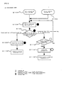
- numeral 10 designates a controller, which comprises an ID reading circuit 12, a CPU (microcomputer) 14, a power source circuit 16, an ignition circuit 18 and a memory 20 made up of an EEPROM (electrically erasable programmable read-only memory) etc.
- This controller 10 has the function of prohibiting engine starting (referred to as immobilizer function) to a key 34 having no ID code which has been registered upon communication between the controller and a built-in transponder 36 of the key.
- Numeral 22 designates a battery, which supplies power to the power source circuit 16 through a main switch (represented by main SW in the figure) described later.
- the power source circuit 16 supplies sections of the controller 10 with respective voltages.
- the power source circuit 16 contains a self-holding circuit 16A capable of continuing operation of the power source circuit 16 for a given length of time even if the main switch 30 is turned off (Fig. 6)
- An ignition permitting signal (a) is inputted to said ignition circuit 18 from a holding circuit 18A for holding the ignition permitting signal (a) described hereinafter, and then the ignition circuit 18 operates according to the ignition permitting signal (a). Once the ignition permitting signal (a) is inputted, the holding circuit holds it until the main switch is selected to 'OFF.'
- Numeral 12 designates an engine and the ignition circuit 18 is comprised of a CDI (capacitor discharging ignition device) etc.
- the ignition circuit 18 generates a spark at an ignition plug 24A of the engine 24 according to an ignition signal determined under operating conditions by an ignition timing control section (not shown) in the CPU 14.
- the structure of the ignition circuit 18 should be changed depending on the type of engine 24, and when an electric motor is employed for the engine 24, for example, the ignition circuit 18 may be constituted by an electric circuit, such as a PWM (pulse width modification) control circuit, which is capable to change drive force of the motor.
- the engine 24 is characterized by a wide sense including an electric motor etc and the ignition circuit 18 constitutes the engine control section of the invention.
- the memory 20 stores ID codes or other various kinds of data, and no stored information is erased even when the power supply is cut off (main switch 30 may be turned off). However, as described later, under a certain condition, for example, when an all clear key is used, or at the time of re-registration of a master key or sub-keys, all (ID codes of the master key and sub-keys) or some (ID codes of sub-keys) of the ID codes other than the one of the all-clear key can be erased electrically.
- the ID code of the all-clear key is stored unerasable as a fixed data, as described above.
- Numeral 26 represents an indicator using LCDs or LEDs, which has not only meters, such as a speed meter etc, for ordinary running, but also an operation display section 26A which indicates warnings and immobilizer system operations as described later.
- Numeral 28 represents a key cylinder, which contains the main switch 30 and an antenna 32 (see FIg.6).
- Numeral 34 represents a key, in the stem of which is embedded a transponder 36. Keys 34 with a transponder includes one master key, a sub-key 1 and a sub-key 2, but are generally referred to simply as a key 34. Also, an all-clear key is used as a special key 34, and functions of these keys 34 are described later.
- the power source circuit 16 begins operating and the controller 10 is activated.
- the ID reading circuit 12 then sends an electric wave to the key 34 through the antenna 32 by radio.
- a given amount of power is stored in the transponder 36, it sends back a proper ID code to the antenna 32.
- the ID reading circuit 12 decodes the ID code signal and sends it to the CPU 14.
- the CPU 14 has functions of an ID determination section 14A, an ID erasing section 14B, an ID registration section 14C, a timer 14D and other sections such as an ignition timing control section etc. These functions are actually constituted by pieces of software.
- the ID determination section 14A compares an ID code read in the ID reading circuit 12 with an ID code registered in the memory 20, and if the ID code read in the ID reading circuit 12 is determined to be the registered one in the memory 20, a signal for allowing engine starting (ignition permitting signal) (a) is sent to the holding circuit 18A. Once the holding circuit 18A receives the signal (a), it continues to send this signal (a) to the ignition circuit (a) until the main switch 30 is selected to 'OFF". If the ID code read in the ID reading circuit 12 does not coincide with the registered one in the memory 20, a signal which prohibits engine starting (ignition prohibiting signal) is sent to the ignition circuit 18.
- the ID erasing section 14D erases all or some of the ID codes other than the one of the all-clear key from the memory 20 at the time of alteration or re-registration of the ID codes.
- the ID registration section 14 registers a new ID code in the memory 20.
- the controller 10 registers the ID code of the all-clear key in the memory 20 as a fixed data, which is unerasable.
- the controller 10 when no other ID codes, that is, no ID codes of the master key, the sub-key 1 and the sub-key 2 are stored in the memory 20, a key 34 with a transponder which is used initially, is registered as a master key, and keys 34 with a transponder which are subsequently inserted successively according to a certain procedure, are registered as a sub-key 1 and sub-key 2, respectively.
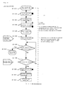
- the sub-key 1 and the sub-key 2 are used. In this case, operation is shown in Fig. 3.
- the sub-key 1 or the sub-key 2 is inserted in the key cylinder 28 to be turned, causing the main switch 30 to be turned on (step S100 in Fig. 3).
- the power source circuit 16 is forced on (step S102), and the controller 10 is activated.
- the ID reading circuit 12 reads the ID code of the inserted sub-key (step S104), and the ID determination section 14A determines whether or not the ID code of the sub-key has been registered in the memory 20 (step S106).
- an ignition permitting signal (a) is sent to the ignition circuit 18 through the holding circuit 18A (step S108), enabling the engine 24 to start (step S110).
- step S108 an ignition permitting signal
- step S110 enabling the engine 24 to start
- step S110 the vehicle is enabled to run. Since operation during steps S100-S110 are normal, no warnings are indicated on the operation display section 26A of the indicator 26. That is, the operation display section 26A made of LCDs or LEDs for indicating operations of the immobilizer system is neither turn on nor flashed.
- step S106 If the ID code of the inserted sub-key has not been registered in the memory 20 (step S106), while the elapsed time is within 5 sec after the main switch 30 has been turned on, the operation display section 26A is lighted continuously for a given time (5 sec) (step S114), and thereafter flashed at short time intervals (period of 1 sec) (step S114), disabling engine starting (step S116). Operations in the operation display section 26 are shown in Fig. 8 by OPERATING CONDITION (2). This condition can be cancelled if the main switch 30 is turned on with a regular key 34.
- the master key is inserted in the key cylinder 28 and the main switch 30 is turned on (step S120 in Fig. 4).
- the ID reading circuit 12 reads the ID code of the master key (step S122), and the ID registration section 14C stores (that is, registers) the ID code as a master key in the memory 20 (step S 124).
- the CPU 14 sends an ignition permitting signal (a) to the ignition circuit 18 through the holding circuit 18A (step S126), enabling the engine 24 to start. Then, registration of the master key to the vehicle is completed, enabling shipment of the vehicle after final inspection (step S128).
- step S130 When the main switch 30 is turned off to draw out the master key (step S130), the engine 24 is stopped, but the self-holding circuit 16A of the power source circuit 16 allows the controller to continue operating. Also, the elapsed time is monitored after the main switch 30 has been turned off, and when a predetermined time (10 sec) has elapsed (step S132), the self-holding circuit 16A is disconnected, the power supply of the controller 10 is cut off, and all the operation is finished (step S134).
- step S136 When the all-clear key is inserted during operation of the self-holding circuit 16A (step S136), the ID code of the all-clear key is read in (step S138), and if the ID code coincides with an ID code of the all-clear key which has been stored in the memory 20, all the stored ID codes other than that of the all-clear key are erased from the memory 20 (step S140). Then, the all-clear key is drawn out, enabling re-registration of the master key (step S142). That is, another master key with a different ID code can be registered.
- transmission and reception of signals may be repeated several time for the ID code.
- reading of the ID code may be repeated a plurality of times when charging of the transponder 36 through the antenna 32 takes much time, or for prevention of misreading of the ID code.
- the operation display section 26A is flashed at slow time intervals until an ignition permitting signal (a) is issued. This flashing is repeated at time intervals of 2 sec for 9 sec as shown in Fig. 8 by OPERATING CONDITION (3). That is, it is flashed 5 times.
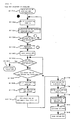
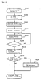
- step S152 the controller 10 is switched on, and the ID code of the new key inserted is read in (step S152).
- This ID code has not been registered in the memory 20, so that as a result of comparison (step S154), it is determined that the ID code does not coincide with a registered ID code.
- step S156 the operation display section 26A is lighted continuously (step S156), and after 5 second, an ignition prohibiting signal b is issued, the operating display section being switched to flashing at short time intervals (step S158).
- step S160 if the main switch 30 is turned off and the new key (unregistered) is drawn out (step S160), then the self-holding circuit 16A functions for 10 sec, and the controller 10 continues operating (step S162). Unless the all-clear key or the old master key is inserted during that time, that is, during the time the operation display section 26A is being flashed at short time intervals, the self-holding circuit 16A is disconnected and the power supply is cut off (step S164). If the all-clear key or the old master key is inserted during the time the operation display section 26A is being flashed at short time intervals (step S166), an ID code of the inserted key is read in (step S168). This ID code has been registered in the memory 20 of the controller 10, so that the CPU 14 erases all the registered ID codes (other than the ID code of the all-clear key) in the memory 20 (step S170).
- a new key can be registered as a master key according to a procedure similar to that of registration of a new master key as shown in Fig. 4. That is, the main switch is turned on with a new key (step S174), the ID code is read in (step S174), and this ID code is registered as an ID code of the new master key (step S178).
- the CPU 14 sends an ignition permitting signal (a) to the ignition circuit 18 through the holding circuit 18A to allow engine starting (step S180).
- step S182 registration of sub-keys is performed as follows:
- a sub-key 1 is registered, as described in Fig. 7 by FUNCTION (4) "Registration of sub-key ID,” within a predetermined time (10 sec) after the main key is drawn out, another key with a transponder is inserted and the main switch 30 is turned on.
- a sub-key 2 is registered according to the following procedure: within a predetermined time (10 sec) after the main switch 30 is turned off with the sub-key 1 and the sub-key 2 is drawn out, another key with a transponder is inserted to turn the main switch 30 on.
- a new sub-key may be registered according to the following procedure. That is, the main switch 30 is turned on with the sub-key which is left behind, then turned off, and within a predetermined time (10 sec), a new key with a transponder is inserted to turn the main switch on.
- the operation display section 26A is flashed five times (9 sec) at time intervals of 2 sec within a period of time during which registration is possible, it is easily confirmed that registration is possible while the operation display section 16A is being flashed.
- the operation display section 26A is not flashed, so that it can be determined from indication on the operation display section 26A whether the first or the second sub-key is registered.
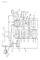
- Fig. 7 illustrates a concept of registration/erasing of ID codes, showing that all of the ID codes stored in the memory 20 other than the one of the all-clear key are erased by the all-clear key at the time of shipment of the vehicle.
- a plurality of all-clear keys are preferably provided in the factory and kept by respective persons in charge.
- Line registration shows the procedure of registering a master key, as is shown in Fig.4.
- User registration and user re-registration are described in Fig.7 by FUNCTION (4).
- Fig.8 shows description of operations displayed on the indicator 26, operating condition 1 states that in the ordinary use, for example, when the main switch 30 is turned on with a registered sub-key, or the second sub-key is to be registered, the operation display section 26A is not lighted. In this case, it is lighted if comparison is not finished in one communication act or registration is not completed in three successive communication acts. This lighting operation is changed as shown in Fig.8, depending on the operating conditions 1-4. As a result, it becomes possible to determine from the state of lighting what is the operating state at that time.
- the controller 10 operates (step S220) when the main switch 30 is turned on and then the power source on using the key which has been registered. If the ID determination section 14A determines that the ID code of the key is the correct ID code registered (step S222), an ignition permitting signal (a) is outputted to the holding circuit 18A (step S226). The holding circuit 18A maintains the signal (a) until the main switch 30 is turned off. The signal (a) is then sent to the ignition circuit 18.
- the ignition circuit 18 usually controls the engine to allow the engine to operate (step S228). After running and turning the main switch off (step S228), the holding circuit 18A completes to hold the signal (a), and then the ignition circuit 18 stops the operation of the engine (step S232).
- the self-holding circuit 16A of the source circuit 16 operates during a predetermined time period after turning off of the main switch 30. ID code can be registered or re-registered within the predetermined time period of the self-holding circuit 16A (step S234), as described heretofore. If the self-holding time period is over, the power source is turned off to complete.
- the ignition permitting signal is output, it is held to enable the continuing operation of the engine until the main switch is turned off. Accordingly, even if in vehicle running, the computer is reset by noises or the like, temporal misfire (which leads to stoppage of the engine) and reduction in output of the engine are not occurred, allowing the vehicle to be operated smoothly.
- a controller is so constituted that once an ignition permitting signal is output, it is held to enable the continuing operation of the engine until the main switch is turned off.
Description
This
Claims (10)
- A method of preventing car thefts providing a key cylinder (28) and a controller (10) mounted on a vehicle body, a key (34) insertable in said key cylinder (28) for switching on a main switch (30), and a built-in transponder (36) in said key (34) for identifying an ID code of said key (34) when said key (34) is inserted in said key cylinder (28), engine (24) starting being allowed when the ID code identified by said transponder (36) coincides with an ID code which has been registered in said controller (10), said method comprising the steps of:wherein said ignition permission signal is directly input to said ignition circuit (18) from said holding circuit (18A).reading an ID code of a key (34) accessing to said key cylinder (28);determining whether or not the ID code read has been registered in a memory (20) and outputting an ignition permission signal when the code has been already registered;holding said ignition permission signal in a holding circuit (18A) until said main switch (30) is switched off; andcontrolling the engine (24) by an engine controlling means (14, 18) according to said ignition permission signal held in said holding circuit (18A), said engine controlling means (14, 18) comprising an ignition circuit (18),
- A method according to claim 1, wherein ID codes of more than one key (34) are registered in said memory (20).
- A method according to claim 2, wherein at least one of said registered ID codes is an ID code of a sub-key (34).
- A method according to claim 2 or 3, wherein one of said registered ID codes is an ID code of a master key (34) which can be used to erase registered ID codes of sub-keys (34).
- A method according to any one of claims 2 to 4, wherein one of said registered ID codes is an ID code of an all-clear key (34) which can be used to erase registered ID codes other than that of said all-clear key (34).
- A device for preventing car thefts having a key cylinder (28) and a controller (10) mounted on a vehicle body, a key (34) insertable in said key cylinder (28) for switching on a main switch (30), and a built-in transponder (36) in said key (34) for identifying an ID code of said key (34) when said key (34) is inserted in said key cylinder (28), engine (24) starting being allowed when the ID code identified by said transponder (36) coincides with an ID code which has been registered in said controller (10), said device comprising:wherein said ignition permission signal is directly input to said ignition circuit (18) from said holding circuit (18A).a memory (20) in which the ID code of said key (34) is registered;an ID reading circuit (12) for reading an ID code of a key (34) accessing to said key cylinder (28);an ID determination section (14A) for determining whether or not the ID code read by said ID reading circuit (12) has been registered in said memory (20) and for outputting an ignition permission signal when the code has been already registered;a holding circuit (18A) for holding said ignition permission signal until said main switch (30) is switched off; andan engine controlling means (14, 18) for controlling the engine (24) according to said ignition permission signal held in said holding circuit (18A), said engine controlling means (14, 18) comprising an ignition circuit (18),
- A device according to claim 6, wherein ID codes of more than one key (34) are registered in said memory (20).
- A device according to claim 7, wherein at least one of said registered ID codes is an ID code of a sub-key (34).
- A device according to claim 7 or 8, wherein one of said registered ID codes is an ID code of a master key (34) which can be used to erase registered ID codes of sub-keys (34).
- A device according to any one of claims 7 to 9, wherein one of said registered ID codes is an ID code of an all-clear key (34) which can be used to erase registered ID codes other than that of said all-clear key (34).
Applications Claiming Priority (2)
| Application Number | Priority Date | Filing Date | Title |
|---|---|---|---|
| JP25084499A JP4237343B2 (en) | 1999-09-03 | 1999-09-03 | Vehicle theft prevention method and apparatus |
| JP25084499 | 1999-09-03 |
Publications (3)
| Publication Number | Publication Date |
|---|---|
| EP1081002A2 EP1081002A2 (en) | 2001-03-07 |
| EP1081002A3 EP1081002A3 (en) | 2001-06-13 |
| EP1081002B1 true EP1081002B1 (en) | 2003-11-05 |
Family
ID=17213861
Family Applications (1)
| Application Number | Title | Priority Date | Filing Date |
|---|---|---|---|
| EP00118847A Expired - Lifetime EP1081002B1 (en) | 1999-09-03 | 2000-08-31 | Method of preventing car thefts |
Country Status (6)
| Country | Link |
|---|---|
| EP (1) | EP1081002B1 (en) |
| JP (1) | JP4237343B2 (en) |
| CN (1) | CN1158201C (en) |
| DE (1) | DE60006334T2 (en) |
| ID (1) | ID27141A (en) |
| TW (1) | TW580467B (en) |
Families Citing this family (10)
| Publication number | Priority date | Publication date | Assignee | Title |
|---|---|---|---|---|
| JP4562408B2 (en) * | 2003-03-27 | 2010-10-13 | 株式会社クボタ | Vehicle anti-theft system |
| JP2005219694A (en) * | 2004-02-09 | 2005-08-18 | Moric Co Ltd | Anti-theft method and device of vehicle |
| JP2007023686A (en) * | 2005-07-20 | 2007-02-01 | Toyota Motor Corp | Unlocking controller |
| JP5144947B2 (en) * | 2006-07-07 | 2013-02-13 | ヤマハ発動機株式会社 | Vehicle anti-theft system and vehicle equipped with anti-theft system |
| CN102285353B (en) * | 2011-06-09 | 2012-09-05 | 宁波市鄞州永林电子电器有限公司 | Alarm device for automotive safety |
| CN102285354B (en) * | 2011-06-09 | 2012-09-26 | 宁波市鄞州永林电子电器有限公司 | Alarm device for car |
| JP5882783B2 (en) * | 2012-02-21 | 2016-03-09 | 株式会社東海理化電機製作所 | Electronic key registration system |
| JP6153215B2 (en) * | 2012-04-30 | 2017-06-28 | カルソニックカンセイ株式会社 | Immobilizer system |
| CN102874212B (en) * | 2012-06-13 | 2015-05-13 | 浙江吉利汽车研究院有限公司杭州分公司 | Automobile theft prevention monitoring system based on voice recognition technology |
| CN103465866A (en) * | 2013-09-25 | 2013-12-25 | 北京汽车股份有限公司 | Vehicle starting control method, vehicle starting control device and vehicle |
Family Cites Families (4)
| Publication number | Priority date | Publication date | Assignee | Title |
|---|---|---|---|---|
| JP3427572B2 (en) * | 1994-09-26 | 2003-07-22 | 株式会社デンソー | Anti-theft devices for vehicles, etc. |
| JP3380687B2 (en) * | 1996-09-13 | 2003-02-24 | 株式会社ミツバ | Engine ignition control method |
| JP3299127B2 (en) * | 1996-09-26 | 2002-07-08 | 株式会社ミツバ | Engine ignition control device |
| JP3380688B2 (en) * | 1996-10-03 | 2003-02-24 | 株式会社ミツバ | Anti-theft method for vehicles |
-
1999
- 1999-09-03 JP JP25084499A patent/JP4237343B2/en not_active Expired - Fee Related
-
2000
- 2000-08-31 DE DE2000606334 patent/DE60006334T2/en not_active Expired - Fee Related
- 2000-08-31 EP EP00118847A patent/EP1081002B1/en not_active Expired - Lifetime
- 2000-09-01 CN CNB001264915A patent/CN1158201C/en not_active Expired - Fee Related
- 2000-09-01 TW TW89117843A patent/TW580467B/en not_active IP Right Cessation
- 2000-09-01 ID ID20000741A patent/ID27141A/en unknown
Also Published As
| Publication number | Publication date |
|---|---|
| JP2001071869A (en) | 2001-03-21 |
| CN1158201C (en) | 2004-07-21 |
| JP4237343B2 (en) | 2009-03-11 |
| EP1081002A2 (en) | 2001-03-07 |
| DE60006334D1 (en) | 2003-12-11 |
| EP1081002A3 (en) | 2001-06-13 |
| TW580467B (en) | 2004-03-21 |
| CN1287070A (en) | 2001-03-14 |
| ID27141A (en) | 2001-03-08 |
| DE60006334T2 (en) | 2004-09-23 |
Similar Documents
| Publication | Publication Date | Title |
|---|---|---|
| US6501369B1 (en) | Vehicle security system having unlimited key programming | |
| JP4193922B2 (en) | Vehicle theft prevention method and apparatus | |
| US5734330A (en) | Anti-theft car protection device | |
| AU681539B2 (en) | Vehicle anti-theft device | |
| EP0682608B1 (en) | Vehicle security system | |
| US7369936B2 (en) | Remote start control system including an engine speed data bus reader and related methods | |
| CA2215279C (en) | Anti-theft system and method for a vehicle | |
| EP1081002B1 (en) | Method of preventing car thefts | |
| EP1081001B1 (en) | Method of preventing car thefts | |
| AU776946B2 (en) | Vehicle usage control and security apparatus | |
| EP1561653B1 (en) | Antitheft method and device for vehicle | |
| US6982626B2 (en) | System and method for activation of remote features from an automotive vehicle | |
| US5815087A (en) | Anti-theft sysem for a removable accessory of an automotve vehicle | |
| US6683391B1 (en) | Method of preventing car thefts | |
| US6653747B1 (en) | Electronic key system including ignition and transmission control | |
| US20130033369A1 (en) | Electronic anti-theft apparatus and system for vehicles | |
| US6888265B2 (en) | Motor vehicle immobilizer with key-in warning responsive to ignition state | |
| US20040239187A1 (en) | Motor vehicle electronic control device with theft-prevention function, and method of controlling motor vehicle engine | |
| US5949152A (en) | Method of and system for entering identification codes into vehicle antitheft system | |
| US6335576B1 (en) | Remote keyless entry receiver having correctly matched transmitters | |
| JP2008001132A (en) | Vehicular security control device | |
| US5982292A (en) | Method of and system for entering identification codes into vehicle antitheft system | |
| JP2001071868A (en) | Antitheft method and system for vehicle | |
| EP0842834A1 (en) | Engine starting control apparatus | |
| JP2001115705A (en) | Smart entry system for vehicle |
Legal Events
| Date | Code | Title | Description |
|---|---|---|---|
| PUAI | Public reference made under article 153(3) epc to a published international application that has entered the european phase |
Free format text: ORIGINAL CODE: 0009012 |
|
| AK | Designated contracting states |
Kind code of ref document: A2 Designated state(s): DE FR IT |
|
| AX | Request for extension of the european patent |
Free format text: AL;LT;LV;MK;RO;SI |
|
| PUAL | Search report despatched |
Free format text: ORIGINAL CODE: 0009013 |
|
| AK | Designated contracting states |
Kind code of ref document: A3 Designated state(s): AT BE CH CY DE DK ES FI FR GB GR IE IT LI LU MC NL PT SE |
|
| AX | Request for extension of the european patent |
Free format text: AL;LT;LV;MK;RO;SI |
|
| RAP1 | Party data changed (applicant data changed or rights of an application transferred) |
Owner name: KABUSHIKI KAISHA MORIC |
|
| 17P | Request for examination filed |
Effective date: 20010803 |
|
| 17Q | First examination report despatched |
Effective date: 20011106 |
|
| AKX | Designation fees paid |
Free format text: DE FR IT |
|
| GRAH | Despatch of communication of intention to grant a patent |
Free format text: ORIGINAL CODE: EPIDOS IGRA |
|
| GRAS | Grant fee paid |
Free format text: ORIGINAL CODE: EPIDOSNIGR3 |
|
| GRAA | (expected) grant |
Free format text: ORIGINAL CODE: 0009210 |
|
| RIN1 | Information on inventor provided before grant (corrected) |
Inventor name: ENOYOSHI, MASAHIKO,C/O MORIYAMA KOGYO K. K. Inventor name: ISODA, NAOYA,C/O MORIYAMA KOGYO K. K. Inventor name: YAMAMOTO, MASAYUKI,C/O MORIYAMA KOGYO K. K. |
|
| AK | Designated contracting states |
Kind code of ref document: B1 Designated state(s): DE FR IT |
|
| REF | Corresponds to: |
Ref document number: 60006334 Country of ref document: DE Date of ref document: 20031211 Kind code of ref document: P |
|
| PLBE | No opposition filed within time limit |
Free format text: ORIGINAL CODE: 0009261 |
|
| STAA | Information on the status of an ep patent application or granted ep patent |
Free format text: STATUS: NO OPPOSITION FILED WITHIN TIME LIMIT |
|
| 26N | No opposition filed |
Effective date: 20040806 |
|
| EN | Fr: translation not filed | ||
| REG | Reference to a national code |
Ref country code: FR Ref legal event code: RN |
|
| REG | Reference to a national code |
Ref country code: FR Ref legal event code: FC |
|
| ET | Fr: translation filed | ||
| PGFP | Annual fee paid to national office [announced via postgrant information from national office to epo] |
Ref country code: DE Payment date: 20080912 Year of fee payment: 9 |
|
| PGFP | Annual fee paid to national office [announced via postgrant information from national office to epo] |
Ref country code: FR Payment date: 20080818 Year of fee payment: 9 Ref country code: IT Payment date: 20080828 Year of fee payment: 9 |
|
| REG | Reference to a national code |
Ref country code: FR Ref legal event code: ST Effective date: 20100430 |
|
| PG25 | Lapsed in a contracting state [announced via postgrant information from national office to epo] |
Ref country code: FR Free format text: LAPSE BECAUSE OF NON-PAYMENT OF DUE FEES Effective date: 20090831 Ref country code: DE Free format text: LAPSE BECAUSE OF NON-PAYMENT OF DUE FEES Effective date: 20100302 |
|
| PG25 | Lapsed in a contracting state [announced via postgrant information from national office to epo] |
Ref country code: IT Free format text: LAPSE BECAUSE OF NON-PAYMENT OF DUE FEES Effective date: 20090831 |