EP1080353B1 - Verspannungsprüfstand für hubschraubergetriebe - Google Patents
Verspannungsprüfstand für hubschraubergetriebe Download PDFInfo
- Publication number
- EP1080353B1 EP1080353B1 EP99924926A EP99924926A EP1080353B1 EP 1080353 B1 EP1080353 B1 EP 1080353B1 EP 99924926 A EP99924926 A EP 99924926A EP 99924926 A EP99924926 A EP 99924926A EP 1080353 B1 EP1080353 B1 EP 1080353B1
- Authority
- EP
- European Patent Office
- Prior art keywords
- stress
- torque
- test rig
- test
- transmission
- Prior art date
- Legal status (The legal status is an assumption and is not a legal conclusion. Google has not performed a legal analysis and makes no representation as to the accuracy of the status listed.)
- Expired - Lifetime
Links
- 238000012360 testing method Methods 0.000 title claims description 75
- 230000005540 biological transmission Effects 0.000 title claims 11
- 230000008878 coupling Effects 0.000 claims description 17
- 238000010168 coupling process Methods 0.000 claims description 17
- 238000005859 coupling reaction Methods 0.000 claims description 17
- 230000007257 malfunction Effects 0.000 claims description 7
- 238000006073 displacement reaction Methods 0.000 claims description 6
- 230000007246 mechanism Effects 0.000 claims description 6
- 238000000034 method Methods 0.000 claims description 6
- 230000001419 dependent effect Effects 0.000 claims description 2
- 230000007935 neutral effect Effects 0.000 claims description 2
- 230000001105 regulatory effect Effects 0.000 claims 5
- 230000006978 adaptation Effects 0.000 description 4
- 238000009434 installation Methods 0.000 description 4
- 238000006243 chemical reaction Methods 0.000 description 3
- 239000012528 membrane Substances 0.000 description 2
- 229910000838 Al alloy Inorganic materials 0.000 description 1
- 229910000851 Alloy steel Inorganic materials 0.000 description 1
- 241000446313 Lamella Species 0.000 description 1
- 229910000861 Mg alloy Inorganic materials 0.000 description 1
- 230000004913 activation Effects 0.000 description 1
- XAGFODPZIPBFFR-UHFFFAOYSA-N aluminium Chemical compound [Al] XAGFODPZIPBFFR-UHFFFAOYSA-N 0.000 description 1
- 230000008901 benefit Effects 0.000 description 1
- 238000010276 construction Methods 0.000 description 1
- 230000005489 elastic deformation Effects 0.000 description 1
- 238000005265 energy consumption Methods 0.000 description 1
- 239000000463 material Substances 0.000 description 1
- 230000009467 reduction Effects 0.000 description 1
- 238000005096 rolling process Methods 0.000 description 1
- 238000004088 simulation Methods 0.000 description 1
Images

Classifications
-
- G—PHYSICS
- G01—MEASURING; TESTING
- G01M—TESTING STATIC OR DYNAMIC BALANCE OF MACHINES OR STRUCTURES; TESTING OF STRUCTURES OR APPARATUS, NOT OTHERWISE PROVIDED FOR
- G01M13/00—Testing of machine parts
- G01M13/02—Gearings; Transmission mechanisms
-
- G—PHYSICS
- G01—MEASURING; TESTING
- G01M—TESTING STATIC OR DYNAMIC BALANCE OF MACHINES OR STRUCTURES; TESTING OF STRUCTURES OR APPARATUS, NOT OTHERWISE PROVIDED FOR
- G01M13/00—Testing of machine parts
- G01M13/02—Gearings; Transmission mechanisms
- G01M13/021—Gearings
-
- G—PHYSICS
- G01—MEASURING; TESTING
- G01M—TESTING STATIC OR DYNAMIC BALANCE OF MACHINES OR STRUCTURES; TESTING OF STRUCTURES OR APPARATUS, NOT OTHERWISE PROVIDED FOR
- G01M13/00—Testing of machine parts
- G01M13/02—Gearings; Transmission mechanisms
- G01M13/025—Test-benches with rotational drive means and loading means; Load or drive simulation
Definitions
- the invention relates to a tension test bench for Helicopter gearbox with the features according to the generic term of claim 1.
- Helicopter gearboxes branch drive power from one to three prime movers for speed reductions on different drives, such as main rotor, tail rotor and Auxiliary drives. These specifically highly stressed gearboxes are small according to the requirements in aviation and easily executed.
- the gearboxes are predominant made of aluminum and magnesium alloys.
- the elastic modulus of these materials is half up to a third of the modulus of elasticity of steel alloys, d. that is, the elastic deformations are below Load correspondingly higher. In particular, a twist occurs of the gearbox around the rotor shaft axis.
- Some of the relocations are carried out in the helicopter torsionally rigid, angularly movable multi-plate or membrane couplings balanced. A significant part of the relocations is, however, due to the generally very long connecting waves to the prime movers or tail rotor output balanced.
- the object underlying the invention is to further develop a generic tension test bench that the most exact possible simulation in a small installation space the loads occurring in the helicopter is.
- the tension test bench should be flexible different helicopter gearbox types and load profiles be adaptable and high security against impermissible Have loads or damage.
- the object is achieved in that for attachment of the test gear by at least one actuator the platen that rotates the rotor shaft axis of the test gear is provided. This arrangement enables the displacements on the connecting couplings occurring under load of the test gear fully or partially.
- connection points for gear feet or foot flanges of the test gear are open the platen arranged so that the axis of rotation of the Platen at least approximately with the rotor shaft axis coincides.
- the arrangement of the platen, the Actuators and if necessary. required adaptation gear on the assembly cart allows a standardized Connection point from the assembly cart to the test bench.
- An advantageous arrangement of the actuators results itself if two actuators are located opposite each other symmetrically are provided, each between a junction the platen and a connection point of the assembly carriage tangential to the direction of rotation of the clamping plate are arranged. Through this. The arrangement remains Storage of the rotating platen on the assembly trolley at least almost free of radial forces.
- the bracing mechanism in a manner known per se a tensioning motor with a microprocessor-controlled electrical torque control unit and a superposition gear on. This will make the torque dependent Activation of the actuators facilitates, in particular, if an electronic actuator control unit with a signal input for a tightening torque setpoint and at least one signal output for a position setpoint an actuator or the platen is provided is.
- a high level of security can be achieved if in the tension circle at least one torque sensor is arranged and the electronic actuator control unit at least a signal input for an actual torque value of the torque sensor or if at least one Sensor for the actual position value of an actuator or the Platen is provided.
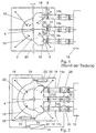
- the known test gear 2 shown in FIG. 1 has a rotor shaft 4 running perpendicular to the plane of the drawing on.
- the rotor shaft is not driven with one in FIG. 1 Upper test bench gear 52 shown connected.
- the test gear 2 is fastened by means of four struts 18 on a test bench Assembly trolley 20 fixed.
- One that occurs under load Reaction torque of the test gear 2 is essentially by means of gear feet (not shown), foot flanges or horizontal struts on the assembly trolley 20 transfer. It acts between these connection points under load and the rotor shaft the reaction torque, which too a housing deformation of the test gear 2 leads.
- Fig. 2 shows schematically one. Part of an inventive Tension test bench in top view.
- the below Loads occurring on the connecting couplings 12 are rotatable about the axis of the rotor shaft 4 Platen 23 balanced.
- the twisting of the Platen opposite the assembly carriage 20 is made by two hydraulically or electrically operated actuators 22, which are symmetrically opposite each other Junction 24 of the platen and a junction 26 of the assembly carriage tangential to the direction of rotation of the Platen are arranged.
- torque sensors 28, 30, 32, 34 for determination the actual value of the tightening torque.
- Fig. 4 This can from the sum of the signal values of the Torque sensors 28, 30 and 32. or from the signal value of the torque sensor 34 arranged on the rotor shaft be determined.
- the actuator control unit shown in FIG. 2 36 has a signal input for the actual torque value of the tightening torque and signal outputs for the Position setpoints of the actuators 22. Depending on that Signal input will be the signal outputs, for example through a linear relationship with the signal input, so dimensioned that the displacements on the connecting couplings 12 be balanced. Other procedures are based on Fig. 4 described.
- Fig. 3 shows a schematic representation of a part a tension test stand according to the invention in side view. Corresponding to each other. Parts have the same reference numbers Mistake.
- the test gear transmits this the reaction moment resulting from the translation via not shown Foot flanges on the around the axis of the rotor shaft rotating platen 23.
- the additional between Test gear and assembly car arranged struts 18 transmitted in the helicopter essentially the one between rotor and helicopter cell occurring vertical forces as well Nodding and rolling moments.
- the platen 23 is with the Bearing 56 in the assembly carriage 20 with respect to the axis of rotation or the rotor shaft axis axially displaceable. Hereby tensions are avoided.
- the rotor shaft 4 is via a clutch 58 to the upper test bench gear 52 connected. Between rotor shaft 4 and upper test bench gear a torque sensor 34 is arranged.
- the top Test bench gear 52 is not shown in FIG. 3 Shaft connections with the lower test bench gear coupled, whereby the tension circuit is closed.
- Fig. 4 shows schematically the test bench structure as well the control devices.
- Motor 38 drives the lower one Test bench gearbox 16 and equalizes that in the clamping ring power losses occurring.
- the tension circle between lower test bench gear 16, test gear 2nd and upper test bench gear 52 is through the shaft 54 and the superposition gear 40 is closed.
- the superposition gear 40 has an input from a bracing motor with a microprocessor-controlled electrical torque control unit 42 on. This bracing mechanism 40, 42 generates depending on the tightening torque setpoint 44 Tensioning moment in the tensioning circle. Structure and functionality the tensioning mechanism is not the subject of this invention.
- the electronic actuator control unit 36 receives the signal of the tightening torque setpoint 44 and outputs a nominal position value 48 for the actuator 22.
- a linear relationship between the two signals Since it is the tightening torque setpoint 44 is a tax variable, is a time behavior caused by feedback avoided. In principle, however, it is also possible to set an actual torque value 46 of a torque sensor 34 for generation of the position setpoint 48 to use. Instructs the actuator control unit 36 both a signal input for the tightening torque setpoint 44 and a signal input for the actual tightening torque value 46, the Comparison of these signals a malfunction of the test bench be diagnosed to avoid damage switch off the test bench if necessary.
- Is used by the actuator control unit 36 also a signal 50 from a sensor evaluated for the actual position value, a Malfunction of the actuators can be determined. Gives way to Actual position value by a certain amount from the position setpoint can also assume a malfunction or reacted accordingly. If the actual torque value 46 due to a malfunction suddenly drops, the actuators 22 immediately in an accelerated emergency mode to a neutral starting position hazards.
Landscapes
- Physics & Mathematics (AREA)
- General Physics & Mathematics (AREA)
- Testing Of Devices, Machine Parts, Or Other Structures Thereof (AREA)
Description
Es zeigen:
- Fig. 1
- eine schematische Draufsicht auf einen Teil eines bekannten Verspannungsprüfstands;
- Fig. 2
- eine schematische Draufsicht auf einen Teil eines erfindungsgemäßen Verspannungsprüfstands;
- Fig. 3
- eine schematische. Seitenansicht eines. Teiles eines erfindungsgemäßen Verspannungsprüfstands und
- Fig. 4
- eine schematische Darstellung der Steuerung des Verspannungsprüfstands.
- 2
- Prüfgetriebe
- 4
- Rotorwelle
- 6
- Eintrieb
- 8
- Eintrieb
- 10
- Abtrieb
- 12
- Verbindungskupplung
- 14a,b,c
- Wellen
- 16
- unteres Prüfstandsgetriebe
- 18
- Strebe
- 20
- Montagewagen
- 22
- Aktuator
- 23
- Aufspannplatte
- 24
- Anschlußstelle
- 26
- Anschlußstelle
- 28
- Drehmomentsensor
- 30
- Drehmomentsensor
- 32
- Drehmomentsensor
- 34
- Drehmomentsensor
- 36
- Aktuator-Steuer-/Regeleinheit
- 38
- Motor
- 40
- Überlagerungsgetriebe
- 42
- Verspannmotor mit mikroprozessor-gesteuerter Regeleinheit
- 44
- Verspannmoment-Sollwert
- 46
- Verspannmoment-Istwert
- 48
- Positions-Sollwert
- 50
- Positions-Istwert
- 52
- oberes Prüfstandsgetriebe
- 54
- Welle
- 56
- Lager
- 58
- Kupplung
- β1,2,3
- Winkel
Claims (13)
- Verspannungsprüfstand für Hubschraubergetriebe mit einem ersten Prüfstandsgetriebe (16), das von einem Motor (38) angetrieben wird und über Wellen (4, 14, 54), Verbindungskupplungen (12, 58), einem Verspannmechanismus (40, 42), einem zweiten Prüfstandsgetriebe (52) und einem Prüfgetriebe (2), welches eine abtriebsseitige Rotorwelle (4) aufweist, einen Verspannkreis bildet, dadurch gekennzeichnet, daß zur Aufnahme des Prüfgetriebes (2) eine durch mindestens einen Aktuator (22) um die Rotorwellenachse des Prüfgetriebes (2) verdrehbare Aufspannplatte (23) vorgesehen ist, um unter Last auftretende Verlagerungen an den Verbindungskupplungen (12) des Prüfgetriebes auszugleichen.
- Verspannungsprüfstand nach Anspruch 1, dadurch gekennzeichnet, daß die verdrehbare Aufspannplatte (23) und die Aktuatoren (22) auf einem Montagewagen (20) angeordnet sind, der das Prüfgetriebe (2) und alle erforderlichen Adaptionseinrichtungen aufnimmt.
- Verspannungsprüfstand nach Anspruch 2, dadurch gekennzeichnet, daß zwei sich symmetrisch gegenüberliegende Aktuatoren (22) vorgesehen sind, welche jeweils zwischen einer Anschlußstelle (24) der Aufspannplatte (23) und einer Anschlußstelle (26) des Montagewagens (20) tangential zur Drehrichtung der Aufspannplatte (23) angeordnet sind.
- Verspannungsprüfstand nach einem der Ansprüche 1 bis 3, dadurch gekennzeichnet, daß die Aufspannplatte (23) durch ein Lager (56) bezüglich ihrer Verdrehachse axial verschieblich gelagert ist.
- Verspannungsprüfstand nach einem der Ansprüche 1 bis 4, dadurch gekennzeichnet, daß der Verspannmechanismus einen Verspannmotor mit einer mikroprozessorgesteuerten elektrischen Verspannmoment-Regeleinheit (42) sowie ein Überlagerungsgetriebe (40) aufweist.
- Verspannungsprüfstand nach einem der Ansprüche 1 bis 5, dadurch gekennzeichnet, daß eine elektronische Aktuator-Steuer-/Regeleinheit (36) mit einem Signaleingang für einen Verspannmoment-Sollwert (44) und mindestens einem Signalausgang für einen Positions-Sollwert (48) eines Aktuators (22) bzw. der Aufspannplatte (23) vorgesehen ist, zur verspannmomentabhängigen Ansteuerung der Aktuatoren (22).
- Verspannungsprüfstand nach Anspruch 6, dadurch gekennzeichnet, daß im Verspannkreis mindestens ein Drehmoment-Sensor (34) angeordnet ist und die elektronische Aktuator-Steuer-/Regeleinheit (36) mindestens einen Signaleingang für einen Verspannmoment-Istwert (46) des Drehmoment-Sensors (34) aufweist.
- Verspannungsprüfstand nach einem der Ansprüche 1 bis 7, dadurch gekennzeichnet, daß mindestens ein Sensor für den Positions-Istwert (50) eines Aktuators (22) bzw. der Aufspannplatte (23) vorgesehen ist.
- Verfahren zum Betrieb eines Verspannungsprüfstands nach einem der Ansprüche 1 bis 8, dadurch gekennzeichnet, daß die Aktuatoren (22) abhängig vom Verspannmoment im Verspannkreis angesteuert werden, so daß Verlagerungen an den Verbindungskupplungen (12) des Prüfgetriebes, welche infolge des Verspannmoments eintreten, ausgeglichen werden.
- Verfahren nach Anspruch 9, dadurch gekennzeichnet, daß die Aktuatoren (22) abhängig vom Verspannmoment-Sollwert (44) angesteuert werden.
- Verfahren nach Anspruch 10 für einen Verspannungsprüfstand nach Anspruch 7 oder 8, dadurch gekennzeichnet, daß die Werte von Verspannmoment-Ist- (46) und -Sollwert (44) in der elektronischen Aktuator-Steuer-/Regeleinheit (36) verglichen werden, um eine Fehlfunktion zu erkennen.
- Verfahren nach einem der Ansprüche 9 bis 11 für einen Verspannungsprüfstand nach Anspruch 8, dadurch gekennzeichnet, daß die Werte von Positions-Ist- (50) und -Sollwert (48) in der elektronischen Aktuator-Steuer-/Regeleinheit (36) verglichen werden, um eine Fehlfunktion zu erkennen.
- Verfahren nach Anspruch 11, dadurch gekennzeichnet, daß bei einem plötzlichen Abfall des Verspannmoment-Istwerts aufgrund einer Fehlfunktion die Aktuatoren sofort in einem beschleunigten Notbetrieb in eine neutrale Ausgangsstellung gefahren werden.
Applications Claiming Priority (3)
| Application Number | Priority Date | Filing Date | Title |
|---|---|---|---|
| DE19822093 | 1998-05-16 | ||
| DE19822093A DE19822093A1 (de) | 1998-05-16 | 1998-05-16 | Verspannungsprüfstand für Hubschraubergetriebe |
| PCT/EP1999/003199 WO1999060362A1 (de) | 1998-05-16 | 1999-05-10 | Verspannungsprüfstand für hubschraubergetriebe |
Publications (2)
| Publication Number | Publication Date |
|---|---|
| EP1080353A1 EP1080353A1 (de) | 2001-03-07 |
| EP1080353B1 true EP1080353B1 (de) | 2001-12-05 |
Family
ID=7868048
Family Applications (1)
| Application Number | Title | Priority Date | Filing Date |
|---|---|---|---|
| EP99924926A Expired - Lifetime EP1080353B1 (de) | 1998-05-16 | 1999-05-10 | Verspannungsprüfstand für hubschraubergetriebe |
Country Status (4)
| Country | Link |
|---|---|
| US (1) | US6393904B1 (de) |
| EP (1) | EP1080353B1 (de) |
| DE (2) | DE19822093A1 (de) |
| WO (1) | WO1999060362A1 (de) |
Cited By (2)
| Publication number | Priority date | Publication date | Assignee | Title |
|---|---|---|---|---|
| CN106908239A (zh) * | 2017-04-21 | 2017-06-30 | 中国航发沈阳发动机研究所 | 一种剪切销承载载荷及其分配的测量方法 |
| CN107797100A (zh) * | 2017-10-24 | 2018-03-13 | 陕西黄河集团有限公司 | 超小型大功率雷达随动系统闭合回路模拟负载台 |
Families Citing this family (26)
| Publication number | Priority date | Publication date | Assignee | Title |
|---|---|---|---|---|
| DE10135976B4 (de) * | 2001-07-24 | 2012-02-23 | Zf Luftfahrttechnik Gmbh | Prüfstand für Hubschraubergetriebe |
| FR2831664B1 (fr) * | 2001-10-29 | 2004-07-30 | Eurocopter France | Banc d'essai pour tester un dispositif de transmission de puissance et systeme d'essai comprenant un tel banc d'essai pourvu d'un dispositif de transmission de puissance |
| FR2833349B1 (fr) * | 2001-12-07 | 2004-05-28 | Eurocopter France | Banc d'essai et systeme d'essai pour tester un dispositif de transmission de puissance |
| RU2237235C2 (ru) * | 2002-04-05 | 2004-09-27 | Пензенская государственная сельскохозяйственная академия | Способ нагружения зубчатых передач, карданных валов и муфт на испытательных и обкаточных стендах |
| US6954685B2 (en) * | 2002-04-23 | 2005-10-11 | Lord Corporation | Aircraft vehicular propulsion system monitoring device and method |
| US7925392B2 (en) | 2002-04-23 | 2011-04-12 | Lord Corporation | Aircraft vehicular propulsion system monitoring device and method |
| WO2005083626A2 (en) * | 2003-10-14 | 2005-09-09 | Lord Corporation | Magnetostrictive sensor for measuring distances |
| US8188879B2 (en) * | 2007-05-24 | 2012-05-29 | Federal Law Enforcement Development Services, Inc. | LED light global positioning and routing communication system |
| US7654135B2 (en) * | 2008-05-16 | 2010-02-02 | Caterpillar Inc. | Multiple transmission test system and method |
| IT1394574B1 (it) * | 2009-07-07 | 2012-07-05 | Rodriquez Marine System Srl | Banco prova a circuito chiuso. |
| US8758184B2 (en) | 2010-08-20 | 2014-06-24 | Redviking Group, Llc | Transmission test system |
| US8783119B2 (en) | 2012-09-26 | 2014-07-22 | United Technologies Corporation | Vane arm testing rig |
| CN102914433B (zh) * | 2012-11-06 | 2015-05-20 | 东南大学 | 一种电模拟机械惯量的方法 |
| CN103207079A (zh) * | 2013-05-06 | 2013-07-17 | 北京理工大学 | 高转速变速箱实验台 |
| DE102014002263B4 (de) * | 2014-02-20 | 2024-02-08 | Renk Test System Gmbh | Hubschraubergetriebeprüfstand |
| US9995650B2 (en) | 2014-12-29 | 2018-06-12 | Dan MERON | Transmission test rig comprising belt drives |
| DE102016202334A1 (de) | 2016-02-16 | 2017-08-17 | Zf Friedrichshafen Ag | Unterbaugruppe für eine Antriebseinheit, Antriebseinheit, Antriebsstrangprüfstand und Baukastensystem |
| CN106323630A (zh) * | 2016-10-21 | 2017-01-11 | 济南大学 | 一种电磁封闭式加载装置 |
| FR3086755B1 (fr) | 2018-09-28 | 2021-06-11 | Airbus Helicopters | Systeme d'essais d'une boîte de transmission de puissance |
| US10829246B2 (en) * | 2018-11-12 | 2020-11-10 | The Boeing Company | Aircraft transmission test fixture and system |
| FR3102816B1 (fr) | 2019-10-30 | 2022-07-15 | Airbus Helicopters | système de transmission d’efforts à limitation de couple |
| CN110920930B (zh) * | 2019-12-04 | 2022-09-13 | 中国直升机设计研究所 | 一种直升机平尾载荷标定方法 |
| WO2021152482A1 (en) | 2020-01-27 | 2021-08-05 | Mts Sensor Technologie Gmbh & Co. Kg | Magnetostrictive position measurement using frequency domain analysis |
| DE102020208040B4 (de) | 2020-06-29 | 2024-08-22 | Zf Friedrichshafen Ag | Verstellbare Prüflingsaufnahme für einen Antriebsstrangprüfstand und Antriebsstrangprüfstand |
| CN111855201B (zh) * | 2020-09-01 | 2022-03-22 | 常州华创航空科技有限公司 | 一种直升机主减速器试验台 |
| CN114955001B (zh) * | 2022-06-17 | 2024-05-31 | 重庆大学 | 直升机尾传动系统模拟实验系统 |
Family Cites Families (10)
| Publication number | Priority date | Publication date | Assignee | Title |
|---|---|---|---|---|
| GB1140115A (en) * | 1966-08-12 | 1969-01-15 | Brown Gear Ind | An improvement in or relating to epicyclic gear trains |
| US4159642A (en) * | 1978-03-02 | 1979-07-03 | Avco Corporation | Aircraft transmission test set |
| DE7812143U1 (de) * | 1978-04-21 | 1978-08-24 | Henschel Flugzeug-Werke Ag, 3500 Kassel | Adapter fuer im verspannungspruefstand zu pruefende getriebe, insbesondere hubschraubergetriebe |
| US4395904A (en) * | 1979-05-18 | 1983-08-02 | Ivanov Gely M | Device for damping oscillations |
| US5207097A (en) * | 1992-08-12 | 1993-05-04 | Gei Systems, Inc. | Gear tester with actuator supported platform |
| US5307676A (en) | 1992-08-12 | 1994-05-03 | Gei Systems, Inc. | Controllable gear testing system |
| DE4325403C2 (de) * | 1993-07-29 | 1995-11-02 | Zf Luftfahrttechnik Gmbh | Verspannungsprüfstand |
| FR2731795B1 (fr) * | 1995-03-16 | 1997-06-06 | Eurocopter France | Banc d'essai pour rotors de giravions |
| DE19616729A1 (de) | 1996-04-26 | 1997-10-30 | Zf Luftfahrttechnik Gmbh | Verspannungsprüfstand für Hubschraubergetriebe |
| US5852793A (en) * | 1997-02-18 | 1998-12-22 | Dme Corporation | Method and apparatus for predictive diagnosis of moving machine parts |
-
1998
- 1998-05-16 DE DE19822093A patent/DE19822093A1/de not_active Withdrawn
-
1999
- 1999-05-10 EP EP99924926A patent/EP1080353B1/de not_active Expired - Lifetime
- 1999-05-10 US US09/674,726 patent/US6393904B1/en not_active Expired - Fee Related
- 1999-05-10 WO PCT/EP1999/003199 patent/WO1999060362A1/de not_active Ceased
- 1999-05-10 DE DE59900507T patent/DE59900507D1/de not_active Expired - Lifetime
Cited By (3)
| Publication number | Priority date | Publication date | Assignee | Title |
|---|---|---|---|---|
| CN106908239A (zh) * | 2017-04-21 | 2017-06-30 | 中国航发沈阳发动机研究所 | 一种剪切销承载载荷及其分配的测量方法 |
| CN106908239B (zh) * | 2017-04-21 | 2019-08-23 | 中国航发沈阳发动机研究所 | 一种剪切销承载载荷及其分配的测量方法 |
| CN107797100A (zh) * | 2017-10-24 | 2018-03-13 | 陕西黄河集团有限公司 | 超小型大功率雷达随动系统闭合回路模拟负载台 |
Also Published As
| Publication number | Publication date |
|---|---|
| DE59900507D1 (de) | 2002-01-17 |
| WO1999060362A1 (de) | 1999-11-25 |
| EP1080353A1 (de) | 2001-03-07 |
| US6393904B1 (en) | 2002-05-28 |
| DE19822093A1 (de) | 1999-11-18 |
Similar Documents
| Publication | Publication Date | Title |
|---|---|---|
| DE19822093A1 (de) | Verspannungsprüfstand für Hubschraubergetriebe | |
| EP0895585B1 (de) | Verspannungsprüfstand für hubschraubergetriebe | |
| EP1955976A1 (de) | Windenvorrichtung | |
| EP4257848A1 (de) | Getriebesystem | |
| DE102012222637A1 (de) | Turnantrieb für eine Windenergieanlage und Verfahren zum Drehen der Rotorwelle einer Windenergieanlage | |
| DE10257614B4 (de) | Prüfstand und Prüfsystem zum Testen einer Vorrichtung zur Leistungsübertragung | |
| DE102023131082B4 (de) | Simulationstestsystem für Schläge und Vibrationen der Zahnräder eines Doppelmotor-Zahnradgetriebes | |
| DE3933505A1 (de) | Hubwerk | |
| AT512104B1 (de) | Prüfstand und Verfahren zum Testen eines drehmomentübertragenden Bauteils | |
| DE102016202332A1 (de) | Unterbaugruppe für eine Abtriebseinheit, Abtriebseinheit, Antriebsstrangprüfstand und Baukastensystem | |
| DE10135976B4 (de) | Prüfstand für Hubschraubergetriebe | |
| EP0603453B1 (de) | Verfahren zur Geräuschverminderung an einem Getriebe und Getriebe zur Durchführung dieses Verfahrens | |
| EP3572628B1 (de) | Dampfturbinenanordnung | |
| WO2018019616A1 (de) | Antriebsvorrichutng und verfahren zur drehzahllimitierung | |
| EP1140548A1 (de) | Verfahren zum überwachen eines stufenlosen getriebes | |
| DE102013206061B4 (de) | Betätigungsvorrichtung einer aerodynamisch wirksamen Fläche | |
| DE102019118476A1 (de) | Handkraftaktuator mit einer Vielzahl von Widerstandsmotoren | |
| DE102022108016A1 (de) | Getriebesystem | |
| EP0175802B1 (de) | Getriebe für die Übertragung extrem hoher Leistungen mit grossem Übersetzungsverhältnis | |
| DE102019209157A1 (de) | Gelenkwellenanordnung | |
| DE102019208548B4 (de) | Getriebe für einen Ruderpropellerantrieb und Ruderpropellerantrieb | |
| DE9013918U1 (de) | Hubwerk | |
| DE102024108196A1 (de) | Drehmomentübertragungsbauteil für ein Getriebe | |
| EP4390119A1 (de) | Planetengetriebe sowie antriebsstrang und windkraftanlage mit einem entsprechenden planetengetriebe | |
| EP4621255A1 (de) | Drehmomentübertragungsbauteil für ein getriebe |
Legal Events
| Date | Code | Title | Description |
|---|---|---|---|
| PUAI | Public reference made under article 153(3) epc to a published international application that has entered the european phase |
Free format text: ORIGINAL CODE: 0009012 |
|
| AK | Designated contracting states |
Kind code of ref document: A1 Designated state(s): DE FR GB IT |
|
| 17P | Request for examination filed |
Effective date: 20000907 |
|
| GRAG | Despatch of communication of intention to grant |
Free format text: ORIGINAL CODE: EPIDOS AGRA |
|
| GRAG | Despatch of communication of intention to grant |
Free format text: ORIGINAL CODE: EPIDOS AGRA |
|
| GRAH | Despatch of communication of intention to grant a patent |
Free format text: ORIGINAL CODE: EPIDOS IGRA |
|
| 17Q | First examination report despatched |
Effective date: 20010517 |
|
| GRAH | Despatch of communication of intention to grant a patent |
Free format text: ORIGINAL CODE: EPIDOS IGRA |
|
| GRAA | (expected) grant |
Free format text: ORIGINAL CODE: 0009210 |
|
| AK | Designated contracting states |
Kind code of ref document: B1 Designated state(s): DE FR GB IT |
|
| REG | Reference to a national code |
Ref country code: GB Ref legal event code: IF02 |
|
| REF | Corresponds to: |
Ref document number: 59900507 Country of ref document: DE Date of ref document: 20020117 |
|
| GBT | Gb: translation of ep patent filed (gb section 77(6)(a)/1977) |
Effective date: 20020204 |
|
| PLBE | No opposition filed within time limit |
Free format text: ORIGINAL CODE: 0009261 |
|
| STAA | Information on the status of an ep patent application or granted ep patent |
Free format text: STATUS: NO OPPOSITION FILED WITHIN TIME LIMIT |
|
| 26N | No opposition filed | ||
| PGFP | Annual fee paid to national office [announced via postgrant information from national office to epo] |
Ref country code: DE Payment date: 20120502 Year of fee payment: 14 |
|
| PGFP | Annual fee paid to national office [announced via postgrant information from national office to epo] |
Ref country code: GB Payment date: 20120509 Year of fee payment: 14 Ref country code: FR Payment date: 20120608 Year of fee payment: 14 |
|
| PGFP | Annual fee paid to national office [announced via postgrant information from national office to epo] |
Ref country code: IT Payment date: 20120516 Year of fee payment: 14 |
|
| GBPC | Gb: european patent ceased through non-payment of renewal fee |
Effective date: 20130510 |
|
| PG25 | Lapsed in a contracting state [announced via postgrant information from national office to epo] |
Ref country code: DE Free format text: LAPSE BECAUSE OF NON-PAYMENT OF DUE FEES Effective date: 20131203 |
|
| PG25 | Lapsed in a contracting state [announced via postgrant information from national office to epo] |
Ref country code: IT Free format text: LAPSE BECAUSE OF NON-PAYMENT OF DUE FEES Effective date: 20130510 |
|
| REG | Reference to a national code |
Ref country code: FR Ref legal event code: ST Effective date: 20140131 |
|
| REG | Reference to a national code |
Ref country code: DE Ref legal event code: R119 Ref document number: 59900507 Country of ref document: DE Effective date: 20131203 |
|
| PG25 | Lapsed in a contracting state [announced via postgrant information from national office to epo] |
Ref country code: GB Free format text: LAPSE BECAUSE OF NON-PAYMENT OF DUE FEES Effective date: 20130510 |
|
| PG25 | Lapsed in a contracting state [announced via postgrant information from national office to epo] |
Ref country code: FR Free format text: LAPSE BECAUSE OF NON-PAYMENT OF DUE FEES Effective date: 20130531 |