EP1080334B1 - Gap drying with insulation layer between substrate and heated platen - Google Patents
Gap drying with insulation layer between substrate and heated platen Download PDFInfo
- Publication number
- EP1080334B1 EP1080334B1 EP99922965A EP99922965A EP1080334B1 EP 1080334 B1 EP1080334 B1 EP 1080334B1 EP 99922965 A EP99922965 A EP 99922965A EP 99922965 A EP99922965 A EP 99922965A EP 1080334 B1 EP1080334 B1 EP 1080334B1
- Authority
- EP
- European Patent Office
- Prior art keywords
- web
- platen
- substrate
- insulation layer
- drying system
- Prior art date
- Legal status (The legal status is an assumption and is not a legal conclusion. Google has not performed a legal analysis and makes no representation as to the accuracy of the status listed.)
- Expired - Lifetime
Links
- 238000001035 drying Methods 0.000 title claims description 125
- 238000009413 insulation Methods 0.000 title claims description 70
- 239000000758 substrate Substances 0.000 title claims description 54
- 238000000576 coating method Methods 0.000 claims description 41
- 239000012530 fluid Substances 0.000 claims description 36
- 239000011248 coating agent Substances 0.000 claims description 34
- 239000007788 liquid Substances 0.000 claims description 23
- 239000011810 insulating material Substances 0.000 claims description 15
- 238000000034 method Methods 0.000 claims description 14
- 239000000463 material Substances 0.000 claims description 8
- 238000010438 heat treatment Methods 0.000 claims description 4
- 239000002904 solvent Substances 0.000 description 9
- 238000010586 diagram Methods 0.000 description 4
- 239000007787 solid Substances 0.000 description 4
- 241000208125 Nicotiana Species 0.000 description 3
- 235000002637 Nicotiana tabacum Nutrition 0.000 description 3
- 210000004027 cell Anatomy 0.000 description 3
- 238000005516 engineering process Methods 0.000 description 3
- 230000005484 gravity Effects 0.000 description 3
- 230000005855 radiation Effects 0.000 description 3
- IJGRMHOSHXDMSA-UHFFFAOYSA-N Atomic nitrogen Chemical compound N#N IJGRMHOSHXDMSA-UHFFFAOYSA-N 0.000 description 2
- 239000002131 composite material Substances 0.000 description 2
- 230000001627 detrimental effect Effects 0.000 description 2
- 238000009792 diffusion process Methods 0.000 description 2
- 239000004744 fabric Substances 0.000 description 2
- 239000010408 film Substances 0.000 description 2
- 230000004907 flux Effects 0.000 description 2
- 239000006260 foam Substances 0.000 description 2
- 239000013529 heat transfer fluid Substances 0.000 description 2
- 230000007246 mechanism Effects 0.000 description 2
- 238000005299 abrasion Methods 0.000 description 1
- 230000006978 adaptation Effects 0.000 description 1
- 230000009286 beneficial effect Effects 0.000 description 1
- 239000000919 ceramic Substances 0.000 description 1
- 238000009833 condensation Methods 0.000 description 1
- 230000005494 condensation Effects 0.000 description 1
- 238000001816 cooling Methods 0.000 description 1
- 230000007423 decrease Effects 0.000 description 1
- 230000007547 defect Effects 0.000 description 1
- 230000001419 dependent effect Effects 0.000 description 1
- 230000008021 deposition Effects 0.000 description 1
- 230000000694 effects Effects 0.000 description 1
- 239000002657 fibrous material Substances 0.000 description 1
- 210000000497 foam cell Anatomy 0.000 description 1
- 239000011888 foil Substances 0.000 description 1
- 239000007789 gas Substances 0.000 description 1
- 239000012774 insulation material Substances 0.000 description 1
- 239000002184 metal Substances 0.000 description 1
- 229910052757 nitrogen Inorganic materials 0.000 description 1
- 239000004745 nonwoven fabric Substances 0.000 description 1
- 239000000123 paper Substances 0.000 description 1
- 239000004033 plastic Substances 0.000 description 1
- 238000011084 recovery Methods 0.000 description 1
- 238000006748 scratching Methods 0.000 description 1
- 230000002393 scratching effect Effects 0.000 description 1
- 239000000126 substance Substances 0.000 description 1
- 238000011144 upstream manufacturing Methods 0.000 description 1
Images
Classifications
-
- F—MECHANICAL ENGINEERING; LIGHTING; HEATING; WEAPONS; BLASTING
- F26—DRYING
- F26B—DRYING SOLID MATERIALS OR OBJECTS BY REMOVING LIQUID THEREFROM
- F26B3/00—Drying solid materials or objects by processes involving the application of heat
- F26B3/18—Drying solid materials or objects by processes involving the application of heat by conduction, i.e. the heat is conveyed from the heat source, e.g. gas flame, to the materials or objects to be dried by direct contact
- F26B3/20—Drying solid materials or objects by processes involving the application of heat by conduction, i.e. the heat is conveyed from the heat source, e.g. gas flame, to the materials or objects to be dried by direct contact the heat source being a heated surface, e.g. a moving belt or conveyor
-
- F—MECHANICAL ENGINEERING; LIGHTING; HEATING; WEAPONS; BLASTING
- F26—DRYING
- F26B—DRYING SOLID MATERIALS OR OBJECTS BY REMOVING LIQUID THEREFROM
- F26B13/00—Machines and apparatus for drying fabrics, fibres, yarns, or other materials in long lengths, with progressive movement
- F26B13/10—Arrangements for feeding, heating or supporting materials; Controlling movement, tension or position of materials
- F26B13/105—Drying webs by contact with heated surfaces other than rollers or drums
Definitions
- the present invention generally relates to a method and apparatus for drying liquid coatings on a substrate, and more particularly relates to a gap drying system having a substrate traveling over a heated platen where a thin layer of fluid is typically entrapped between the substrate and the heated plate.
- Drying coated substrates typically requires heating the coated substrate to cause liquid to evaporate from the coating. The evaporated liquid is then removed.
- typical conventional impingement drying systems for coated substrates one or two-sided impingement dryer technology is utilized to impinge air to one or both sides of a moving substrate. In such conventional impingement dryer systems, air supports and heats the substrate and can supply heat to both the coated and non-coated sides of the substrate.
- conventional drying technology see E. Cohen and E. Gutoff, Modern Coating and Drying Technology (VCH publishers Inc., 1992).
- a gap drying system such as taught in U.S. -A-5,581,905 WO-A-97/11328, and U.S.
- a coated substrate such as a web
- a coated substrate typically moves through the gap drying system without contacting solid surfaces.
- heat is supplied to the backside of the moving web to evaporate solvent and a chilled platen is disposed above the moving web to remove the solvent by condensation.
- the gap drying system provides for solvent recovery, reduced solvent emissions to the environment, and a controlled and relatively inexpensive drying system.
- the web typically is transported through the drying system supported by a fluid, such as air, which avoids scratches on the web.
- the non-uniform heat transfer coefficient can lead to drying defects.
- the actual effect of operating parameters on the drying rate can usually only be determined after extensive trial and error experimentation.
- One method of obtaining a more uniform heat transfer coefficient to the web is to supply energy from a heated platen to the backside of the web by conduction through a fluid layer between the heated platen and the moving web.
- the amount of energy supplied to the backside of the web is a function of the heated platen temperature and thickness of the fluid layer between the heated platen and the moving web.
- the heat transfer coefficient is inversely proportional to the distance between the heated platen and the moving web. Therefore, in order to obtain large heat transfer coefficients which are comparable to those obtained by air impingement drying systems, the distance between the moving web and the heated platen needs to be very small. In many applications, the web must not touch the heated platen to prevent scratches from occurring in the web.
- a degree of contact between the web and the heated platen is not detrimental to a product produced from the web coated material and high heat transfer rates are required or desired.
- the heat transfer from the heated platen through the fluid layer to the moving web becomes non-uniform.
- the non-uniform heat transfer from the heated platen to the moving web causes non-uniform drying of the coating on the substrate which produces drying patterns on the dried coated web.
- a drying system which provides more uniform heat transfer to the moving coated substrate and more uniform drying of the coating on the substrate to thereby reduce the incidence of drying patterns on the coated substrate caused by non-uniform heat transfer.
- a drying system where the heat transfer and drying rates are more easily controlled.
- the present invention provides a system and method of gap drying a substrate having a coated side and a non-coated side as defined in claims 1 and 6, respectively.
- the dependent claims relate to additional embodiments of the invention.
- a condensing platen is disposed on the coated side of the substrate.
- An insulation layer is disposed between the heated platen and the non-coated side of the substrate. The substrate is moved between the heated platen and the condensing platen.
- a fluid layer is disposed between the substrate and the insulation layer.
- a back clearance distance is defined between a bottom surface of the non-coated side of the substrate and a top surface of the heated platen, and the insulation layer fills the back clearance distance.
- the insulation layer is moved between the heated platen and the substrate. In this embodiment, the insulation layer is moved in a direction opposite to the direction in which the substrate is moved.
- the insulation layer preferably comprises a material that has a thermal conductivity lower than that of the heated platen.
- the gap drying system and method of the present invention provides more uniform heat transfer to the moving coated substrate and more 5 uniform drying of the coating on the substrate than conventional gap drying systems.
- the gap drying system of the present invention reduces the incidence of drying patterns on the coated substrate caused by non-uniform heat transfer.
- the gap drying system of the present invention can be utilized to control the heat transfer to the coated substrate and the drying rates of 10 the coated substrate.
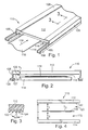
- Gap drying system 110 is similar to the gap drying systems disclosed in US-A-5,581,905, WO-A-97/11328 and US-A-5,694,701.
- Gap drying system 110 includes a condensing platen 112 spaced from a heated platen 114. In one embodiment, condensing platen 112 is chilled.
- a moving substrate or web 116, having a coating 118, travels between condensing platen 112 and heated platen 114 at a web speed V in a direction indicated by arrow 119.
- Some example substrate or web materials are paper, film, plastic, foil, fabric, and metal. Heated platen 114 is stationary within gap drying system 110.
- Heated platen 114 is disposed on the non-coated side of web 116, and there is typically a small fluid clearance, indicated at 132, between web 116 and platen 114.
- Condensing platen 112 is disposed on the coated side of web 116. Condensing platen 112, which can be stationary or mobile, is placed above, but near the coated surface. The arrangement of condensing platen 112 creates a small substantially planar gap 120 above coated web 116.
- Heated platen 114 eliminates the need for applied convection forces below web 116. Heated platen 114 transfers heat substantially without convection through web 116 to coating 118 causing liquid to evaporate from coating 118 to thereby dry the coating. Heat typically is transferred dominantly by conduction, and slightly by radiation and convection, achieving high heat transfer rates. This evaporates the liquid from coating 118 on web 116. Evaporated liquid from coating 118 then travels across gap 120 defined between web 116 and condensing platen 112 and condenses on a condensing surface 122 of condensing platen 112. Gap 120 has a height indicated by arrows h 1 .
- Heated platen 114 is optionally surface treated with functional coatings.
- functional coatings include: coatings to minimize mechanical wear or abrasion of web 116 and/or platen 114; coatings to improve cleanability; coatings having selected emissimity to increase radiant heat transfer contributions; and coatings with selected electrical and/or selected thermal characteristics.
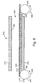
- Figure 3 illustrates a cross-sectional view of condensing platen 112.
- condensing surface 122 includes transverse open channels or grooves 124 which use capillary forces to move condensed liquid laterally to edge plates 126.
- grooves 124 are longitudinal or in any other direction.
- edge plates 126 are substantially perpendicular to condensing surface 122, but edge plates 126 can be at other angles with condensing surface 122. Edge plates 126 can have smooth, capillary, porous media, or other surfaces.
- condensed liquid from condensing surface 122 is moved to prevent the condensed liquid from returning to web 116.
- mechanical devices such as wipers, belts, or scrapers, or any combination thereof, can be used instead of platens to remove condensed liquid.
- fins on condensing surface 122 are used to remove the condensed liquid.
- condensing surface 122 is tilted to use gravity to flow liquid.
- a capillary surface could be used to force or pump liquid to a higher elevation before or instead of using gravity.
- forming condensing surface 122 as a capillary surface facilitates removal of the condensed liquid.
- Heated platen 114 and condensing platen 112 optionally include internal passageways, such as channels.
- a heat transfer fluid is optionally heated by an external heating system (not shown) and circulated through the internal passageways in heated platen 114.
- the same or a different heat transfer fluid is optionally cooled by an external chiller and circulated through passageways in the condensing platen 112.
- FIG 4 illustrates a schematic side view of conventional gap drying system 110 to illustrate certain process variables.
- Condensing platen 112 is set to a temperature T 1 , which can be above or below ambient temperature.
- Heated platen 114 is set to a temperature T 2 , which can be above or below ambient temperature.
- Coated web 116 is defined by a varying temperature T 3 .
- a distance between the bottom surface (condensing surface 122) of condensing platen 112 and the top surface of heated platen 114 is indicated by arrows h.
- a front gap distance between the bottom surface of condensing platen 112 and the top surface of the front (coated) side of web 116 is indicated by arrows h 1 .
- a back clearance distance between the bottom surface of the backside (non-coated side) of web 116 and the top surface of heated platen 114 is indicated by arrows h 2 .
- the position of web 116 is defined by distances h 1 and h 2 .
- distance h is equal to h 1 plus h 2 plus the thickness of coated web 116.
- Heat transfer to web 116 is obtained by supplying energy to the backside of web 116 dominantly by conduction, and slightly by convection and radiation, through thin fluid layer132 between heated platen 114 and moving web 116.
- fluid layer 132 include, but are not limited to air, ionized air, and nitrogen.
- Equation I includes a simplified heat transfer coefficient which is equal to K FLUID /h 2 . According to the heat transfer coefficient portion of equation I, larger heat transfer coefficients are obtained with relatively small back clearance distances h 2 .
- web 116 In many applications of gap drying system 110, web 116 must not touch heated platen 114 to prevent scratches from occurring in web 116. However, in some applications of gap drying system 110, a degree of contact between web 116 and heated platen 114 is not detrimental to a product produced from web 116 coated material and high heat transfer rates are required or desired. In these other types of applications of gap drying system 110, it is advantageous to have the capability of metering away a sufficient amount of fluid layer 132 to enable web 116 to contact heated platen 114.
- Example ranges of back clearance distance h 2 are from approximately zero (for dragging web) to 0.1 inches, or more.
- Equation I applies when back clearance distance h 2 is sufficiently small so that fluid flow in the back clearance between heated platen 114 and moving web 116 is laminar.
- the heat transfer coefficient on the backside of web 116 is a function of the thermal conductivity of fluid (k FLUID ) and back clearance distance h 2 , in addition to any other radiant heat transfer contribution.
- Equations I and II can be used to derive a constant rate type drying model of conventional gap drying system 110.
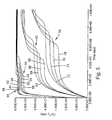
- An example one such constant rate type drying model of gap drying system 110 derived by equations I and II is illustrated in graphical form in Figure 5.
- the rate of drying is lowered and web temperature T 3 becomes slightly higher as front gap distance h 1 is increased.
- web temperature T 3 is approximately two degrees C less than heated platen temperature T 2 when the back clearance distance h 2 is 2.54 ⁇ 10 -3 mm (0.001 inches). However, when the back clearance distance is 50.8 ⁇ 10 -3 mm (0.020 inches), web temperature T 3 is approximately 20 degrees C less than heated platen temperature T 2 .
- Figure 5 also graphically illustrates that the rate of drying decreases substantially as back clearance distance h 2 becomes larger. Therefore, deviations in the position of web 116 which result in changes in back clearance distance h 2 can cause differential drying and patterns in coating 118 on web 116. In addition, it is well known in the art, that temperature gradients within coating 118 cause surface tension driven flow in coating 118 leading to mottle and other undesirable patterns.
- gap drying system 110 it is undesirable for web 116 to bridge back clearance distance h 2 and contact heated platen 114.
- the heat transfer coefficient is essentially infinite at the contact point relative to the bulk of the web. This type of contact between web 116 and heated platen 114 causes streaking type patterns to be formed in the dried coating 118 on web 116. Moreover, contact between web 116 and heated platen 114 can scratch web 116.
- the modeling results illustrated in Figure 5 indicate that at nominal operating conditions for drying, the radiant heat transfer contribution is insignificant. In addition, the modeling results illustrated in Figure 5 indicate that web temperature T 3 and the drying rate are extremely sensitive to variations in the back clearance distance h 2 .
- Gap drying system 210 is generally similar to conventional gap drying system 110 illustrated in Figures 1 and 2.
- Gap drying system 210 includes a condensing platen 212 spaced from a heated platen 214.
- condensing platen 212 is chilled.
- a moving substrate or web 216, having a coating 218, travels between condensing platen 212 and heated platen 214 at a web speed V in a direction indicated by arrow 219. Heated platen 214 is stationary within gap drying system 210.
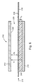
- gap drying system 210 includes an insulation layer 240 comprising insulating material disposed between heated platen 214 and the non-coated side of web 216.
- Condensing platen 212 is disposed on the coated side of web 216.
- Condensing platen 212 which can be stationary or mobile, is placed above, but near the coated surface of web 216. The arrangement of condensing platen 212 creates a small substantially planar gap 220 above coated web 216.
- Heated platen 214 transfers heat through insulation layer 240 to web 216 and through web 216 to coating 218.
- the heat transferred from heated platen 214 to coating 218 causes liquid to evaporate from coating 218 to thereby dry the coating.
- Evaporated liquid from coating 218 then travels across gap 220 defined between web 216 and condensing platen 212 and condenses on a condensing surface 222 of condensing platen 212.
- Gap 220 has a height indicated by arrows h 1 .
- condensing platen 212 is set to a temperature T 1 , which can be above or below ambient temperature.
- Heated platen 214 is set to a temperature T 2 , which can be above or below ambient temperature.
- Coated web 216 is defined by a varying temperature T 3 .
- a distance between the bottom surface (condensing surface 222) of condensing platen 212 and the top surface of heated platen 214 is indicated by arrows h.
- a front gap distance between the bottom surface of condensing platen 212 and the top surface of the front (coated) side of web 216 is indicated by arrows h 1 .
- a back clearance distance between the bottom surface of the backside (non-coated side) of web 216 and the top surface of heated platen 214 is indicated by arrows h 2 .
- the position of web 216 is defined by distances h 1 and h 2 .
- distance h is equal to h 1 plus h 2 plus the thickness of coated web 216.
- insulation layer 240 is formed from insulating material which fills back clearance distance h 2 between the backside of web 216 and heated platen 214. Therefore, in gap drying system 210 of the present invention, insulation layer 240 is not just a fluid (e.g., air) and actually supports moving web 216 to maintain a substantially constant back clearance distance h 2 between moving web 216 and heated platen 214.
- the substantially constant back clearance distance h 2 results in a substantially constant heat transfer coefficient being applied to the backside of web 216.
- heat is more uniformly transferred from heated platen 214 to web 216 through to coating 218.
- the uniform heat transfer leads to a substantially uniform web temperature T 3 throughout web 216 and substantially uniform drying rates of coating 218.
- the substantially uniform web temperature T 3 and drying rates substantially eliminates unwanted patterns in the dried coating material 218.
- Heat transfer to web 216 is obtained by supplying energy to the backside of web 116 dominantly by conduction, and slightly by convection and radiation, through insulation layer 240 between heated platen 214 and moving web 216.
- the amount of energy supplied to the backside of web 116 is determined by platen temperature T 2 and the thickness of insulation layer 240, which is indicated by arrows h 2 .
- Equation III includes a simplified heat transfer coefficient through insulation layer 240 which is equal to K INSULATION /h 2 .
- the heat transfer coefficient for gap drying system 210 of the present invention is calculated similar to the heat transfer coefficient for conventional gap drying system 110, except that the thermal conductivity of insulation layer 240 (k INSULATION ) is used rather than the thermal conductivity of fluid (k FLUID ).
- a criteria for insulation layer 240 is that its thermal conductivity (k INSULATION ) is lower than that of heated platen 214 (k PLATEN ). Most common insulating materials hold air in the layer stagnant (i.e., substantially no convection).
- insulation layer 240 has a thermal conductivity equal to or greater than air.
- the heat transfer coefficient through insulation layer 240 is greater than or equal to the laminar fluid clearance case represented by equation I, when the fluid is air. Consequently, the heat transfer rate and the drying rate are not typically reduced by employing insulating layer 240 according to the present invention.
- the heat transfer coefficient through insulation layer 240 can be selected by specifying the insulating material and the thickness of the insulation layer.
- the insulating material that forms insulation layer 240 preferably has a relatively small feature size (i.e., grain or cell size) so that the feature size pattern cannot transfer to the coating as a non-uniform heat transfer itself.
- insulation layer 240 comprises a solid/air composite, such as a fiber material, non-woven, granular of foam cell
- the solid portion of the solid/air composite preferably has a thermal conductivity substantially close to air to substantially eliminate the possibility of differential heat transfer at touchdown of web 216 to insulation layer 240.
- the insulating material that forms insulation layer 240 is preferably selected along with the material which forms web 216 to provide for scratch free drag of web 216.
- web 216 is preferably clean of dirt prior to entry into gap drying system 210 to avoid scratches on the web.
- Suitable insulating materials for insulation layer 240 include, but are not limited to felts, fabrics, non-wovens, films, open cell foams, closed cell foams, and other such insulating materials.
- Suitable insulating materials for insulation layer 240 can be, for example, ceramic, organic, cellulosic, or polymeric origin, provided that insulation layer 240 meets the criteria that it is thermal conductivity is lower than that of heated platen 214.
- insulation layer 240 is optionally employed in gap drying system 210 to control or slow down heat transfer to web 216 from heated platen 214 for certain applications of gap drying by selecting a heat transfer coefficient by specifying the insulating material and the thickness of the insulation layer.
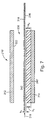
- Gap drying system 210' is similar to gap drying system 210 illustrated in Figure 6 and described above, except that gap drying system 210' of Figure 7 includes an insulation layer 240' which only replaces some of the fluid in back clearance distance h 2 between the backside of web 216 and heated platen 214.
- insulation layer 240 has a height equal to back clearance distance h 2 .
- gap drying system 210' of Figure 7 includes insulation layer 240' having a height or thickness indicated by arrows h 3 and a fluid layer 242 formed between insulation layer 240' and the backside web 216.
- Fluid layer 242 has a height or thickness indicated by arrows h 4 . Therefore, in gap drying system 210', the height of insulation layer 240' (h 3 ) plus the height of fluid layer 242 (h 4 ) is equal to the backside clearance distance h 2 .
- gap drying system 210 of Figure 6 the insulation layer drags web 216.
- web 216 floats over fluid layer 242 above insulation layer 240'.
- insulation layer 210' does not actually directly support moving web 216 to maintain a substantially constant back clearance distance h 2 between moving web 216 and heated platen 214.
- Gap drying system 210' especially is beneficial in situations where web 216 would touch down to heated platen 214 if insulation layer 240' was not disposed between heated platen 214 and web 216.
- Gap drying system 310 is similar to gap drying system 210 illustrated in Figure 6 and described above.
- Gap drying system 310 includes a condensing platen 312 spaced from a heated platen 314.
- condensing platen 312 is chilled.
- a moving substrate or web 316, having a coating 318, travels between condensing platen 312 and heated platen 314 at a web speed V in a direction indicated by arrow 319. Heated platen 314 is stationary within gap drying system 310.
- Gap drying system 310 includes a moving insulation layer 340 comprising insulating material disposed between heated platen 314 and the non-coated side of web 316.
- Condensing platen 312 is disposed on the coated side of web 316.
- Condensing platen 312, which can be stationary or mobile, is placed above, but near the coated surface of web 316. The arrangement of condensing platen 312 creates a small substantially planar gap 320 above coated web 316.
- Heated platen 314 transfers heat through insulation layer 340 to web 316 and through web 316 to coating 318.
- the heat transferred from heated platen 314 to coating 318 causes liquid to evaporate from coating 318 to thereby dry the coating.
- Evaporated liquid from coating 318 then travels across gap 320 defined between web 316 and condensing platen 312 and condenses on a condensing surface 322 of condensing platen 312.
- condensing platen 312 is set to a temperature T 1 , which can be above or below ambient temperature.
- Heated platen 314 is set to a temperature T 2 , which can be above or below ambient temperature.
- Coated web 316 is defined by a varying temperature T 3 .
- Gap drying system 310 includes upstream roller 342 and downstream roller 344 which continuously feed insulation layer 340 in a direction, indicated by arrow 346, which is counter to the web movement direction 319. Rollers 342 and 344 rotate in a counter clockwise direction, as indicated by arrows 348, to feed insulation layer 340 in direction 346.
- the insulation layer 340 is fed at a slow speed relative to the speed V of moving web 316. In this way, a fresh layer of insulating material is maintained between moving web 316 and heated platen 314, which minimizes variations caused be wear or deposition of dirt entrained by web 316.
- Gap drying systems according to the present invention which have an insulation layer between the moving web and the heated platen, such as gap drying systems 210, 210', and 310, provide a more uniform heat transfer to the moving coated web than that provided by conventional gap drying systems, such as conventional gap dry system 110.
- the more uniform heat transfer provides uniform drying of the coating on the web. Drying patterns caused by non-uniform heat transfer, are therefore substantially reduced.
- scratches to the moving web are substantially reduced with a gap drying system of the present invention.
- gap drying systems according to the present invention can more easily control heat transfer and drying rates.
Landscapes
- Engineering & Computer Science (AREA)
- Mechanical Engineering (AREA)
- General Engineering & Computer Science (AREA)
- Textile Engineering (AREA)
- Life Sciences & Earth Sciences (AREA)
- Microbiology (AREA)
- Drying Of Solid Materials (AREA)
- Manufacturing Of Printed Wiring (AREA)
Applications Claiming Priority (3)
| Application Number | Priority Date | Filing Date | Title |
|---|---|---|---|
| US80914 | 1998-05-18 | ||
| US09/080,914 US6134808A (en) | 1998-05-18 | 1998-05-18 | Gap drying with insulation layer between substrate and heated platen |
| PCT/US1999/010400 WO1999060319A1 (en) | 1998-05-18 | 1999-05-12 | Gap drying with insulation layer between substrate and heated platen |
Publications (2)
| Publication Number | Publication Date |
|---|---|
| EP1080334A1 EP1080334A1 (en) | 2001-03-07 |
| EP1080334B1 true EP1080334B1 (en) | 2003-07-30 |
Family
ID=22160460
Family Applications (1)
| Application Number | Title | Priority Date | Filing Date |
|---|---|---|---|
| EP99922965A Expired - Lifetime EP1080334B1 (en) | 1998-05-18 | 1999-05-12 | Gap drying with insulation layer between substrate and heated platen |
Country Status (8)
| Country | Link |
|---|---|
| US (1) | US6134808A (enExample) |
| EP (1) | EP1080334B1 (enExample) |
| JP (1) | JP4302889B2 (enExample) |
| KR (1) | KR100575068B1 (enExample) |
| AU (1) | AU3984199A (enExample) |
| CA (1) | CA2331730C (enExample) |
| DE (1) | DE69910013T2 (enExample) |
| WO (1) | WO1999060319A1 (enExample) |
Families Citing this family (26)
| Publication number | Priority date | Publication date | Assignee | Title |
|---|---|---|---|---|
| USRE38412E1 (en) * | 1996-09-04 | 2004-02-03 | Imation Corp. | Coated substrate drying system with magnetic particle orientation |
| US6256904B1 (en) | 1998-05-06 | 2001-07-10 | Imation Corp. | Controlling float height of moving substrate over curved plate |
| EP1337799B1 (en) | 2000-09-21 | 2007-02-28 | 3M Innovative Properties Company | Vapor collection method and apparatus |
| US7032324B2 (en) * | 2000-09-24 | 2006-04-25 | 3M Innovative Properties Company | Coating process and apparatus |
| US20030230003A1 (en) * | 2000-09-24 | 2003-12-18 | 3M Innovative Properties Company | Vapor collection method and apparatus |
| US7143528B2 (en) * | 2000-09-24 | 2006-12-05 | 3M Innovative Properties Company | Dry converting process and apparatus |
| KR100770812B1 (ko) | 2000-09-24 | 2007-10-26 | 쓰리엠 이노베이티브 프로퍼티즈 캄파니 | 압출 방법, 주조 방법 및 미공성 필름 형성 장치 |
| US6553689B2 (en) | 2000-09-24 | 2003-04-29 | 3M Innovative Properties Company | Vapor collection method and apparatus |
| US7068344B2 (en) * | 2003-02-24 | 2006-06-27 | 3M Innovative Properties Company | Cholesteric liquid crystal optical bodies and methods of manufacture and use |
| US7029729B2 (en) * | 2003-02-24 | 2006-04-18 | 3M Innovative Properties Company | Cholesteric liquid crystal additives |
| US6913708B2 (en) * | 2003-02-24 | 2005-07-05 | 3M Innovative Properties Company | Cholesteric liquid crystal drying process and solvent |
| US7160586B2 (en) * | 2003-08-29 | 2007-01-09 | 3M Innovative Properties Company | Cholesteric liquid crystal copolymers and additives |
| US7378136B2 (en) * | 2004-07-09 | 2008-05-27 | 3M Innovative Properties Company | Optical film coating |
| US7877895B2 (en) * | 2006-06-26 | 2011-02-01 | Tokyo Electron Limited | Substrate processing apparatus |
| BRPI0811705A2 (pt) * | 2007-06-22 | 2015-03-31 | 3M Innovative Properties Co | Aparelhos e método para modificação da carga eletrostática em uma manta em movimento |
| US20090074976A1 (en) * | 2007-09-14 | 2009-03-19 | Freking Anthony J | Method of reducing mottle and streak defects in coatings |
| US8077192B2 (en) * | 2008-01-07 | 2011-12-13 | Zink Imaging, Inc. | Platen temperature model |
| US8742022B2 (en) | 2010-12-20 | 2014-06-03 | 3M Innovative Properties Company | Coating compositions comprising non-ionic surfactant exhibiting reduced fingerprint visibility |
| US9296904B2 (en) | 2010-12-20 | 2016-03-29 | 3M Innovative Properties Company | Coating compositions comprising non-ionic surfactant exhibiting reduced fingerprint visibility |
| ES2625072T3 (es) | 2011-08-11 | 2017-07-18 | Avery Dennison Corporation | Secador de placas y método de secado de revestimientos a base de disolvente |
| JP6003241B2 (ja) * | 2012-05-31 | 2016-10-05 | コニカミノルタ株式会社 | 塗布膜の乾燥装置及び乾燥方法 |
| JP6363072B2 (ja) | 2012-06-19 | 2018-07-25 | スリーエム イノベイティブ プロパティズ カンパニー | 低表面エネルギー基及びヒドロキシル基を含む添加剤、並びにコーティング組成物 |
| WO2013191822A1 (en) | 2012-06-19 | 2013-12-27 | 3M Innovative Properties Company | Coating compositions comprising polymerizable non-ionic surfactant exhibiting reduced fingerprint visibility |
| CN108011050B (zh) | 2016-11-01 | 2019-11-08 | 株式会社日本有机雷特显示器 | 有机el显示面板的制造方法及墨干燥装置 |
| JP7076135B2 (ja) | 2018-07-27 | 2022-05-27 | 株式会社Joled | 有機el表示パネルの製造方法 |
| CN110849082B (zh) * | 2019-10-16 | 2020-10-27 | 深圳市华星光电技术有限公司 | 一种干燥装置 |
Family Cites Families (10)
| Publication number | Priority date | Publication date | Assignee | Title |
|---|---|---|---|---|
| US1592078A (en) * | 1925-09-10 | 1926-07-13 | Cano Vernon | Apparatus for heating, cooling, or drying materials |
| GB862460A (en) * | 1957-02-22 | 1961-03-08 | Coordination Et D Orientation | Drying apparatus |
| AT321257B (de) * | 1971-05-26 | 1975-03-25 | Koreska Gmbh W | Anlage zur Rückgewinnung flüchtiger Lösungsmittel |
| US4413425A (en) * | 1980-08-04 | 1983-11-08 | Candor James T | Method for thermal/vacuum drying a wet web of material |
| US4365423A (en) * | 1981-03-27 | 1982-12-28 | Eastman Kodak Company | Method and apparatus for drying coated sheet material |
| DE58901137D1 (de) * | 1988-05-13 | 1992-05-21 | Hoechst Ag | Verfahren und vorrichtung zum trocknen einer auf einem bewegten traegermaterial aufgebrachten fluessigkeitsschicht. |
| GB9414856D0 (en) * | 1994-07-22 | 1994-09-14 | Tmci Uk Ltd | Production of reconstituted tobacco sheet |
| EP1195564B1 (en) * | 1995-09-18 | 2005-12-28 | Minnesota Mining And Manufacturing Company | Coated substrate drying system |
| US5694701A (en) * | 1996-09-04 | 1997-12-09 | Minnesota Mining And Manufacturing Company | Coated substrate drying system |
| US5581905A (en) * | 1995-09-18 | 1996-12-10 | Minnesota Mining And Manufacturing Company | Coated substrate drying system |
-
1998
- 1998-05-18 US US09/080,914 patent/US6134808A/en not_active Expired - Lifetime
-
1999
- 1999-05-12 WO PCT/US1999/010400 patent/WO1999060319A1/en not_active Ceased
- 1999-05-12 AU AU39841/99A patent/AU3984199A/en not_active Abandoned
- 1999-05-12 KR KR1020007012839A patent/KR100575068B1/ko not_active Expired - Lifetime
- 1999-05-12 JP JP2000549895A patent/JP4302889B2/ja not_active Expired - Fee Related
- 1999-05-12 CA CA002331730A patent/CA2331730C/en not_active Expired - Fee Related
- 1999-05-12 EP EP99922965A patent/EP1080334B1/en not_active Expired - Lifetime
- 1999-05-12 DE DE69910013T patent/DE69910013T2/de not_active Expired - Lifetime
Also Published As
| Publication number | Publication date |
|---|---|
| AU3984199A (en) | 1999-12-06 |
| EP1080334A1 (en) | 2001-03-07 |
| CA2331730C (en) | 2007-07-24 |
| DE69910013T2 (de) | 2004-04-22 |
| WO1999060319A1 (en) | 1999-11-25 |
| CA2331730A1 (en) | 1999-11-25 |
| JP4302889B2 (ja) | 2009-07-29 |
| JP2002515585A (ja) | 2002-05-28 |
| US6134808A (en) | 2000-10-24 |
| DE69910013D1 (de) | 2003-09-04 |
| KR20010043653A (ko) | 2001-05-25 |
| KR100575068B1 (ko) | 2006-05-02 |
Similar Documents
| Publication | Publication Date | Title |
|---|---|---|
| EP1080334B1 (en) | Gap drying with insulation layer between substrate and heated platen | |
| JP3874799B2 (ja) | 被覆基材乾燥システム | |
| US5694701A (en) | Coated substrate drying system | |
| US5581905A (en) | Coated substrate drying system | |
| WO1999002933A1 (en) | Coated substrate drying system with magnetic particle orientation | |
| US6256904B1 (en) | Controlling float height of moving substrate over curved plate | |
| EP0774301A1 (en) | Apparatus for removing material from a coated moving web and coating apparatus using such apparatus | |
| US5181329A (en) | Drying apparatus | |
| US5136966A (en) | Web coating apparatus | |
| USRE38412E1 (en) | Coated substrate drying system with magnetic particle orientation | |
| US6215103B1 (en) | Heat developing apparatus | |
| HK1015025B (en) | Procedure and device for drying a coated substrate | |
| JP2001355062A (ja) | ウェブ上に潤滑剤コーティングを蒸着するための装置及び方法 |
Legal Events
| Date | Code | Title | Description |
|---|---|---|---|
| PUAI | Public reference made under article 153(3) epc to a published international application that has entered the european phase |
Free format text: ORIGINAL CODE: 0009012 |
|
| 17P | Request for examination filed |
Effective date: 20001117 |
|
| AK | Designated contracting states |
Kind code of ref document: A1 Designated state(s): BE DE GB IT NL |
|
| 17Q | First examination report despatched |
Effective date: 20010713 |
|
| GRAH | Despatch of communication of intention to grant a patent |
Free format text: ORIGINAL CODE: EPIDOS IGRA |
|
| GRAH | Despatch of communication of intention to grant a patent |
Free format text: ORIGINAL CODE: EPIDOS IGRA |
|
| GRAA | (expected) grant |
Free format text: ORIGINAL CODE: 0009210 |
|
| AK | Designated contracting states |
Designated state(s): BE DE GB IT NL |
|
| REG | Reference to a national code |
Ref country code: GB Ref legal event code: FG4D |
|
| REF | Corresponds to: |
Ref document number: 69910013 Country of ref document: DE Date of ref document: 20030904 Kind code of ref document: P |
|
| PLBE | No opposition filed within time limit |
Free format text: ORIGINAL CODE: 0009261 |
|
| STAA | Information on the status of an ep patent application or granted ep patent |
Free format text: STATUS: NO OPPOSITION FILED WITHIN TIME LIMIT |
|
| 26N | No opposition filed |
Effective date: 20040504 |
|
| PGFP | Annual fee paid to national office [announced via postgrant information from national office to epo] |
Ref country code: BE Payment date: 20070615 Year of fee payment: 9 |
|
| PGFP | Annual fee paid to national office [announced via postgrant information from national office to epo] |
Ref country code: GB Payment date: 20070525 Year of fee payment: 9 |
|
| BERE | Be: lapsed |
Owner name: *3M INNOVATIVE PROPERTIES CY Effective date: 20080531 |
|
| GBPC | Gb: european patent ceased through non-payment of renewal fee |
Effective date: 20080512 |
|
| PG25 | Lapsed in a contracting state [announced via postgrant information from national office to epo] |
Ref country code: BE Free format text: LAPSE BECAUSE OF NON-PAYMENT OF DUE FEES Effective date: 20080531 |
|
| PG25 | Lapsed in a contracting state [announced via postgrant information from national office to epo] |
Ref country code: GB Free format text: LAPSE BECAUSE OF NON-PAYMENT OF DUE FEES Effective date: 20080512 |
|
| PGFP | Annual fee paid to national office [announced via postgrant information from national office to epo] |
Ref country code: NL Payment date: 20100501 Year of fee payment: 12 Ref country code: IT Payment date: 20100525 Year of fee payment: 12 |
|
| REG | Reference to a national code |
Ref country code: NL Ref legal event code: V1 Effective date: 20111201 |
|
| PG25 | Lapsed in a contracting state [announced via postgrant information from national office to epo] |
Ref country code: NL Free format text: LAPSE BECAUSE OF NON-PAYMENT OF DUE FEES Effective date: 20111201 |
|
| PG25 | Lapsed in a contracting state [announced via postgrant information from national office to epo] |
Ref country code: IT Free format text: LAPSE BECAUSE OF NON-PAYMENT OF DUE FEES Effective date: 20110512 |
|
| PGFP | Annual fee paid to national office [announced via postgrant information from national office to epo] |
Ref country code: DE Payment date: 20180502 Year of fee payment: 20 |
|
| REG | Reference to a national code |
Ref country code: DE Ref legal event code: R071 Ref document number: 69910013 Country of ref document: DE |