EP1079600A2 - Image processing apparatus and method, and storage medium - Google Patents
Image processing apparatus and method, and storage medium Download PDFInfo
- Publication number
- EP1079600A2 EP1079600A2 EP00307291A EP00307291A EP1079600A2 EP 1079600 A2 EP1079600 A2 EP 1079600A2 EP 00307291 A EP00307291 A EP 00307291A EP 00307291 A EP00307291 A EP 00307291A EP 1079600 A2 EP1079600 A2 EP 1079600A2
- Authority
- EP
- European Patent Office
- Prior art keywords
- data
- valued
- image
- bit
- natural number
- Prior art date
- Legal status (The legal status is an assumption and is not a legal conclusion. Google has not performed a legal analysis and makes no representation as to the accuracy of the status listed.)
- Granted
Links
- 238000000034 method Methods 0.000 title claims description 41
- 238000013139 quantization Methods 0.000 claims description 32
- 230000008569 process Effects 0.000 claims description 25
- 238000006243 chemical reaction Methods 0.000 claims description 19
- 238000012856 packing Methods 0.000 claims description 10
- 238000003672 processing method Methods 0.000 claims description 3
- 238000004590 computer program Methods 0.000 claims 2
- 238000013144 data compression Methods 0.000 description 24
- 238000007906 compression Methods 0.000 description 21
- 238000010586 diagram Methods 0.000 description 15
- 230000006835 compression Effects 0.000 description 7
- 230000006870 function Effects 0.000 description 7
- 239000003086 colorant Substances 0.000 description 4
- 230000002542 deteriorative effect Effects 0.000 description 2
- 239000000976 ink Substances 0.000 description 2
- 230000015572 biosynthetic process Effects 0.000 description 1
- 230000008859 change Effects 0.000 description 1
- 238000013500 data storage Methods 0.000 description 1
- 230000003247 decreasing effect Effects 0.000 description 1
- 230000006866 deterioration Effects 0.000 description 1
- 238000009792 diffusion process Methods 0.000 description 1
- 238000004519 manufacturing process Methods 0.000 description 1
- 230000003287 optical effect Effects 0.000 description 1
- 230000009467 reduction Effects 0.000 description 1
Images






Classifications
-
- H—ELECTRICITY
- H04—ELECTRIC COMMUNICATION TECHNIQUE
- H04N—PICTORIAL COMMUNICATION, e.g. TELEVISION
- H04N1/00—Scanning, transmission or reproduction of documents or the like, e.g. facsimile transmission; Details thereof
- H04N1/46—Colour picture communication systems
- H04N1/64—Systems for the transmission or the storage of the colour picture signal; Details therefor, e.g. coding or decoding means therefor
- H04N1/648—Transmitting or storing the primary (additive or subtractive) colour signals; Compression thereof
Definitions
- the present invention relates to an image processing apparatus and method, and a storage medium and, more particularly, to an image processing apparatus and method for quantizing image data.
- the number of tones that can output is limited, is used, the number of tones of image data is reduced to that the printer can express by a quantization process by means of a printer driver on a host computer, and that image data is then transferred from the host computer to the printer.
- the size of image data to be transferred increases and the time required for transferring image data from the host computer to the printer increases with increasing resolution of printer, resulting in a low print throughput.
- the following method may be used. That is, the printer driver sends only tone information of a density pattern using a density pattern method, and the printer converts the received tone information into dots.
- the data size can be smaller than that of binary data to be directly transferred from the host computer to the printer. For example, when the resolution of a printer is 600 dpi, and a unit density pattern is formed by collecting a total of four dots to be output from the printer, i.e., 2 vertical dots ⁇ 2 horizontal dots, five tones can be expressed, as shown in Fig. 1. That is, when the printer driver executes a 5-valued quantization process for 300-dpi pixel information, and sends its tone information alone to the printer, it can make the printer output a pseudo continuous tone image.
- the aforementioned 5-valued quantization data is expressed by quantization codes each having a given bit length, and the quantization codes are packed to undergo data transfer.
- the bit length of each quantization code is 2, 4, or 8 bits, and a 4-bit quantization code is used in case of the 5-valued quantization data. Therefore, since this quantization data has only tone information for five values with respect to 16 tones that 4 bits can express, it becomes information with very high redundancy.
- a preferred embodiment of the present invention comprises an image processing apparatus comprising: quantization means for quantizing multi-valued image data into N-valued data (where N is a natural number), and outputting the N-valued data as a K-bit code (where K is a natural number) that can express the N values; conversion means for combining and converting K-bit codes for M pixels (where M is a natural number) into an L-bit code (where L ⁇ M ⁇ K); and output means for packing and outputting data output from said conversion means into data of a predetermined bit unit.
- the image processor like a printer driver which runs on the host computer 101 executes a quantization process, compression process, and the like of the input image data, thus generating image data to be transferred to a printer 104 such as an ink-jet printer.
- the image data input to the printer 104 is stored in a RAM 105. Since the image data stored in the RAM 105 has been compressed by the image processor 103, it is expanded to image data to be printed by a decoder 106. The expanded image data is sent to an engine 107, thus forming and outputting an image based on the image data.
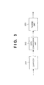
- Fig. 3 is a block diagram showing the arrangement of the image processor 103.
- a quantizer 201 converts input multi-valued (e.g., 8 bits, 256 tones per color) image data into N-valued image data per C, M, or Y, or C, M, Y, or K.
- N 5, i.e., 5-valued quantization is done.
- pseudo halftoning is done to correct quantization errors produced upon quantization, the image finally output has continuous tone.
- pseudo halftoning known error diffusion, dithering, or the like is used.
- a data compression unit 202 inputs the quantized data in units of pixels.
- quantized data since image data is quantized to 5-valued data, quantized data has 4 bits per pixel. This data of 4 bits per pixel is compressed to data of 8 bits per three pixels by a compression process (to be described later) of the data compression unit 202, and the compressed data is sent to a packing unit 203.
- the packing unit 203 packs the compressed data input from the data compression unit 202 into a transfer unit from the host computer 101 to the printer 102. For example, when data transfer from the host computer 101 to the printer 102 is done in units of 16 bits, two 8-bit compressed data are packed into 16-bit data.
- Fig. 4 is a block diagram for explaining the functional arrangement of the data compression unit 202.
- a switch 301 receives 4-bit pixel data, which has been quantized to 5-valued data, in units of pixels, and separately outputs the received pixel data at three pixel cycles 3n, 3n+1, and 3n+2, as shown in Fig. 5.
- pixels a and d are distributed and output as (3n)-th pixels; pixels b and e as (3n+1)-th pixels; and pixels c and f as (3n+2)-th pixels.
- each pixel data is 4-bit data, since five values can be expressed by, e.g., "0000", “0001", “0010", “0011”, and "0100", upper 1 bit is not necessary. For this reason, the bits to be output from the switch 301 can be three bits.
- The(3n)-th and (3n+1)-th pixel data of those distributed to three pixel cycles are input to a look-up table (LUT) 302 and are converted into 5-bit data in accordance with a table example shown in Fig. 6.
- LUT look-up table
- the number of bits of data is reduced by one, but no information is omitted.
- this 5-bit data and 3-bit data as the (3n+2)-th pixel data are combined, and the combined data is output from the data compression unit 202 as 8-bit information.
- the arrangement of the data compression unit 202 is not limited to that shown in Fig. 4, but the arrangement shown in Fig. 7 may be used. That is, all 4-bit data for three pixels may be input to an LUT 601 and converted into 8-bit data. When a process is done by software such as a printer driver, the arrangement shown in Fig. 6 can make the processing load lighter.
- Fig. 8 is a block diagram showing the arrangement of the decoder 106.
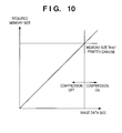
- Fig. 10 is a graph for explaining the relationship among the image data size, required memory size, available memory size, and ON/OFF state of the compression process. Note that the border line of ON/OFF of the compression process may be fixed in accordance with the memory size that the printer 104 can use or may dynamically change on the basis of information obtained from the printer 104.
- Fig. 11 is a block diagram showing the arrangement of an image processing system according to the third embodiment.
- the compression process required for the image processor 103, and the memory size require for data storage at that time can be reduced.
- the processing load can be prevented from increasing due to the compression process in the host computer 101, and hence, low print throughput can be avoided.
- C, M, and K image data are quantized to 5-valued data by the quantizers 201C, 201M, and 201K, the quantized data undergo the same data compression process as in the first embodiment by data compression units 202C, 202M, and 202K, and the compressed data are input to the packing unit 203.
- Y image data is quantized to 4-valued data by the quantizer 201Y. Since 4-valued data can be expressed by 2 bits, the Y image data is sent to the packing unit 203 without being compressed.
- the present invention can be applied to a system constituted by a plurality of devices (e.g., host computer, interface, reader, printer) or to an apparatus comprising a single device (e.g., copy machine, facsimile).
- devices e.g., host computer, interface, reader, printer
- apparatus comprising a single device (e.g., copy machine, facsimile).
- the storage medium such as a floppy disk, a hard disk, an optical disk, a magneto-optical disk, CD-ROM, CD-R, a magnetic tape, a non-volatile type memory card, and ROM can be used for providing the program codes.
- the present invention includes a case where an OS (operating system) or the like working on the computer performs a part or entire processes in accordance with designations of the program codes and realizes functions according to the above embodiments.
Landscapes
- Engineering & Computer Science (AREA)
- Multimedia (AREA)
- Signal Processing (AREA)
- Record Information Processing For Printing (AREA)
- Color, Gradation (AREA)
- Image Processing (AREA)
- Facsimile Image Signal Circuits (AREA)
Abstract
Description
- The present invention relates to an image processing apparatus and method, and a storage medium and, more particularly, to an image processing apparatus and method for quantizing image data.
- When a printer such as an ink-jet printer, the number of tones that can output is limited, is used, the number of tones of image data is reduced to that the printer can express by a quantization process by means of a printer driver on a host computer, and that image data is then transferred from the host computer to the printer.
- The size of image data to be transferred increases and the time required for transferring image data from the host computer to the printer increases with increasing resolution of printer, resulting in a low print throughput. In such case, the following method may be used. That is, the printer driver sends only tone information of a density pattern using a density pattern method, and the printer converts the received tone information into dots. In this method, the data size can be smaller than that of binary data to be directly transferred from the host computer to the printer. For example, when the resolution of a printer is 600 dpi, and a unit density pattern is formed by collecting a total of four dots to be output from the printer, i.e., 2 vertical dots × 2 horizontal dots, five tones can be expressed, as shown in Fig. 1. That is, when the printer driver executes a 5-valued quantization process for 300-dpi pixel information, and sends its tone information alone to the printer, it can make the printer output a pseudo continuous tone image.
- When image data is transferred from the host computer to the printer by the aforementioned method, the aforementioned 5-valued quantization data is expressed by quantization codes each having a given bit length, and the quantization codes are packed to undergo data transfer. In terms of this packing process (since data transfer is done in units of 8 or 16 bits), the bit length of each quantization code is 2, 4, or 8 bits, and a 4-bit quantization code is used in case of the 5-valued quantization data. Therefore, since this quantization data has only tone information for five values with respect to 16 tones that 4 bits can express, it becomes information with very high redundancy.
- Even such highly redundant information, which expresses five tones using 4 bits, can be used while the data transfer rate or the memory size of the printer has a large margin. However, as the printer requires higher resolution and higher speed, the data transfer rate and the data size that the printer can hold pose a problem. That is, when highly redundant information that expresses five tones using 4 bits is transferred to the printer, this results in very poor efficiency.
- In order to combat this problem without changing the unit density pattern, when the number of tones is reduced from five values to four values, the quantization code can be expressed by 2 bits. However, a reduction of the number of tones leads to loss of tone information, production of false contours, an increase in granularity, and the like, thus deteriorating the image quality of an output image.
- The present invention has been made to solve the aforementioned problems, and has as a concern to generate quantization data with low redundancy by quantizing image data without deteriorating image quality.
- Thus, a preferred embodiment of the present invention comprises an image processing apparatus comprising: quantization means for quantizing multi-valued image data into N-valued data (where N is a natural number), and outputting the N-valued data as a K-bit code (where K is a natural number) that can express the N values; conversion means for combining and converting K-bit codes for M pixels (where M is a natural number) into an L-bit code (where L < M × K); and output means for packing and outputting data output from said conversion means into data of a predetermined bit unit.
- An aspect of the invention provides an image processing method comprising the steps of: quantizing multi-valued image data into N-valued data (where N is a natural number), and outputting the N-valued data as a K-bit code (where K is a natural number) that can express the N values; combining and converting K-bit codes for M pixels (where M is a natural number) into an L-bit code (where L < M × K); and packing and outputting data output from the conversion step into data of a predetermined bit unit.
- Other features and advantages of the present invention will be apparent from the following description taken in conjunction with the accompanying drawings, in which like reference characters designate the same or similar parts throughout the figures thereof.
-
- Fig. 1 is a view showing an example of density patterns;
- Fig. 2 is a block diagram showing the arrangement of an image processing system according to the first embodiment of the present invention;
- Fig. 3 is a block diagram showing the arrangement of an image processor shown in Fig. 1;
- Fig. 4 is a block diagram for explaining the functional arrangement of a data compression unit;
- Fig. 5 is a view for explaining the process of the data compression unit;
- Fig. 6 is a view showing an example of a conversion table of an LUT shown in Fig. 4;
- Fig. 7 is a block diagram showing another arrangement of a data compression unit shown in Fig. 3;
- Fig. 8 is a block diagram showing the arrangement of a decoder shown in Fig. 2;
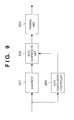
- Fig. 9 is a block diagram showing the arrangement of an image processor according to the second embodiment of the present invention;
- Fig. 10 is a graph for explaining the relationship among the image data size, required memory size, available memory size, and ON/OFF state of a compression process;
- Fig. 11 is a block diagram showing the arrangement of an image processing system according to the third embodiment of the present invention;
- Fig. 12 is a block diagram showing the arrangement of an image processor according to the fourth embodiment of the present invention; and
- Fig. 13 is a view showing an example of density patterns in the fourth embodiment.
-
- An image processing apparatus according to an embodiment of the present invention will be described in detail hereinafter with reference to the accompanying drawings.
- Fig. 2 is a block diagram showing the arrangement of an image processing system according to this embodiment.
-
Application software 102, which runs on ahost computer 101 and is used to create and edit an image, outputs image data of the created and/or edited image to animage processor 103. Image data output from theapplication software 102 is 8-bit multi-valued data per color of R, G, and B or C, M, Y, and K if an image is a continuous tone image. - The image processor like a printer driver which runs on the
host computer 101 executes a quantization process, compression process, and the like of the input image data, thus generating image data to be transferred to aprinter 104 such as an ink-jet printer. - The image data input to the
printer 104 is stored in aRAM 105. Since the image data stored in theRAM 105 has been compressed by theimage processor 103, it is expanded to image data to be printed by adecoder 106. The expanded image data is sent to anengine 107, thus forming and outputting an image based on the image data. - Fig. 3 is a block diagram showing the arrangement of the
image processor 103. - A
quantizer 201 converts input multi-valued (e.g., 8 bits, 256 tones per color) image data into N-valued image data per C, M, or Y, or C, M, Y, or K. In this embodiment, a case will be explained wherein N = 5, i.e., 5-valued quantization is done. Also, since pseudo halftoning is done to correct quantization errors produced upon quantization, the image finally output has continuous tone. As pseudo halftoning, known error diffusion, dithering, or the like is used. - A
data compression unit 202 inputs the quantized data in units of pixels. In this embodiment, since image data is quantized to 5-valued data, quantized data has 4 bits per pixel. This data of 4 bits per pixel is compressed to data of 8 bits per three pixels by a compression process (to be described later) of thedata compression unit 202, and the compressed data is sent to apacking unit 203. - The
packing unit 203 packs the compressed data input from thedata compression unit 202 into a transfer unit from thehost computer 101 to theprinter 102. For example, when data transfer from thehost computer 101 to theprinter 102 is done in units of 16 bits, two 8-bit compressed data are packed into 16-bit data. - Fig. 4 is a block diagram for explaining the functional arrangement of the
data compression unit 202. - A
switch 301 receives 4-bit pixel data, which has been quantized to 5-valued data, in units of pixels, and separately outputs the received pixel data at threepixel cycles switch 301 can be three bits. - The(3n)-th and (3n+1)-th pixel data of those distributed to three pixel cycles are input to a look-up table (LUT) 302 and are converted into 5-bit data in accordance with a table example shown in Fig. 6. As a result, the number of bits of data is reduced by one, but no information is omitted. This is because since 3-bit data for one pixel has only information for five values, there are only 5 × 5 = 25 different pieces of information even when data for two pixels are combined. Furthermore, this 5-bit data and 3-bit data as the (3n+2)-th pixel data are combined, and the combined data is output from the
data compression unit 202 as 8-bit information. - The arrangement of the
data compression unit 202 is not limited to that shown in Fig. 4, but the arrangement shown in Fig. 7 may be used. That is, all 4-bit data for three pixels may be input to an LUT 601 and converted into 8-bit data. When a process is done by software such as a printer driver, the arrangement shown in Fig. 6 can make the processing load lighter. - The compressed image data is transferred to the
printer 104 and is stored in theRAM 105. Thedecoder 106 decodes (expands) image data stored in theRAM 105 in synchronism with the image formation timing of theengine 107. - Fig. 8 is a block diagram showing the arrangement of the
decoder 106. - The
decoder 106 basically executes a process opposite to that of thedata compression unit 202 shown in Fig. 4. That is, 5-bit data extracted from the input 8-bit data is input to anLUT 701 that makes inverse conversion to that of theLUT 302 of thedata compression unit 202 to be converted into 3-bit pixel data for two pixels. The pixel data for two pixels output from theLUT 701, and the remaining 3-bit data of the 8-bit data are input together to aswitch 702 to restore pixel data for three successive pixels.
Finally, the pixel data output from theswitch 702 is supplied to a pattern table 703 to generate five different dot patterns shown in Fig. 1. - As described above, according to the first embodiment, 4-bit information per pixel is compressed to 8-bit data per three pixels, and the compressed data is sent to the
printer 104 and stored in theRAM 105. Hence, image data to be transferred and stored in theRAM 105 is 8/3 - 2.67 bits per pixel, and efficient data transfer and storage can be realized. According to the compression method of this embodiment, since image data undergoes lossless compression, it is free from any omission of information resulting from lossy compression such as JPEG or the like, and is also free from any deterioration of image due to compression. - An image processing apparatus according to the second embodiment of the present invention will be described below. Note that the same reference numerals in this embodiment denote the same parts as in the first embodiment, and a detailed description thereof will be omitted.
- In the second embodiment, the compression process of the
data compression unit 102 described in the first embodiment is ON/OFF-controlled depending on image data. Fig. 9 is a block diagram showing the arrangement of theimage processor 103 of the second embodiment. In Fig. 9, adata compression controller 204 is added to the arrangement of the first embodiment shown in Fig. 3. Thedata compression controller 204 computes the memory size that theprinter 104 requires for processing on the basis of, e.g., the size of image data input to theimage processor 103. When the memory size that theprinter 104 can use is smaller than the required memory size, thedata compression controller 204 controls image data to pass through thedata compression unit 202 without any compression process. - Fig. 10 is a graph for explaining the relationship among the image data size, required memory size, available memory size, and ON/OFF state of the compression process. Note that the border line of ON/OFF of the compression process may be fixed in accordance with the memory size that the
printer 104 can use or may dynamically change on the basis of information obtained from theprinter 104. - The reason why such process is required will be briefly explained. In a serial printer such as an ink-jet printer, the print speed changes largely depending on the image data size, and the processing speed required for the
host computer 101 also changes. Hence, when the compression process is kept ON irrespective of the image data size, the load on the compression process is large when the image data size is small, and data transfer from thehost computer 101 cannot often catch up with the print speed of theprinter 104. If the image data size is originally small, since such data need not be compressed in consideration of the memory size of theRAM 105 of theprinter 104, the compression process of thedata compression unit 202 is preferably turned off so as not to increase the processing load on theimage processor 103. - As described above, according to the second embodiment, since the compression process of the
image processor 103 is ON/OFF-controlled depending on the image data size, efficient data transfer and storage can be realized in case of a relatively large data size, and an increase in processing load due to the compression process can be suppressed in case of a relatively small data size. - An image processing apparatus according to the third embodiment of the present invention will be explained below. Note that the same reference numerals in this embodiment denote the same parts as in the first embodiment, and a detailed description thereof will be omitted.
- The data compression process in the first embodiment is done on the
host computer 101 side. By contrast, the data compression process in the third embodiment is done on theprinter 104 side. Fig. 11 is a block diagram showing the arrangement of an image processing system according to the third embodiment. - In the third embodiment, since the
host computer 101 does not perform any compression, the quantized image data is directly transferred from theimage processor 103 to theprinter 104. Hence, in the example explained in the first embodiment, 4-bit image data that has been quantized to 5-valued data is directly transferred to theprinter 104. The image data input to theprinter 104 is compressed by acompression unit 108 by the same method as that described in the first embodiment, and the compressed data is stored in theRAM 105. - According to the third embodiment, since both the compression and expansion processes of image data are done on the
printer 104 side, the compression process required for theimage processor 103, and the memory size require for data storage at that time can be reduced. Hence, the processing load can be prevented from increasing due to the compression process in thehost computer 101, and hence, low print throughput can be avoided. - An image processing apparatus according to the fourth embodiment of the present invention will be explained below. Note that the same reference numerals in this embodiment denote the same parts as in the first embodiment, and a detailed description thereof will be omitted.
- In the fourth embodiment, in particular, to reduce the data size when a color image is output, coarse quantization is done for a color in which quantization errors hardly stand out, and data compression is done for a color in which quantization errors readily stand out.
- When a color image is formed by an image output apparatus represented by an ink-jet printer, a color image is formed by mixing four different color inks such as cyan, magenta, yellow, and black. For this reason, the use ratios of inks are determined in correspondence with input image data in a color conversion process in the image process, and image data is quantized in units of colors.
- Fig. 12 is a block diagram showing the arrangement of an image processor of the fourth embodiment. For example, RGB 24-bit color image data output from the
application software 102 is input to acolor processor 205, and is color-separated into multi-valued (e.g., 8 bits) data of four colors, i.e., cyan, magenta, yellow, and black (to be abbreviated as C, M, Y, and K hereinafter). Each color data is input to acorresponding quantizer - Of four, C, M, Y, and K colors, Y dots are very hard to see for the human eye. Hence, even when coarse quantization is done for Y image data, quantization errors of a Y component image formed hardly stand out. Hence, exploiting this nature, five tones expressed by 2 × 2 dots are used for three, C, M, and K colors, and Y is expressed by four tones by decreasing one gray level, as shown in Fig. 13. Hence, C, M, and K image data are quantized to 5-valued data by the
quantizers data compression units packing unit 203. On the other hand, Y image data is quantized to 4-valued data by thequantizer 201Y. Since 4-valued data can be expressed by 2 bits, the Y image data is sent to thepacking unit 203 without being compressed. - According to the fourth embodiment, exploiting the nature that respective color components have different influences on image quality, data compression is selectively done for some color components. Hence, the processing load of the overall image process can be reduced, and the influence on image quality can be minimized.
- Note that the fourth embodiment can be combined with not only the arrangement of the first embodiment, but also that of the second embodiment.
- The present invention can be applied to a system constituted by a plurality of devices (e.g., host computer, interface, reader, printer) or to an apparatus comprising a single device (e.g., copy machine, facsimile).
- Further, the object of the present invention can be also achieved by providing a storage medium storing program codes for performing the aforesaid processes to a system or an apparatus, reading the program codes with a computer (e.g., CPU, MPU) of the system or apparatus from the storage medium, then executing the program.
- In this case, the program codes read from the storage medium realize the functions according to the embodiments, and the storage medium storing the program codes constitutes the invention.
- Further, the storage medium, such as a floppy disk, a hard disk, an optical disk, a magneto-optical disk, CD-ROM, CD-R, a magnetic tape, a non-volatile type memory card, and ROM can be used for providing the program codes.
- Furthermore, besides aforesaid functions according to the above embodiments are realized by executing the program codes which are read by a computer, the present invention includes a case where an OS (operating system) or the like working on the computer performs a part or entire processes in accordance with designations of the program codes and realizes functions according to the above embodiments.
- Furthermore, the present invention also includes a case where, after the program codes read from the storage medium are written in a function expansion card which is inserted into the computer or in a memory provided in a function expansion unit which is connected to the computer, CPU or the like contained in the function expansion card or unit performs a part or entire process in accordance with designations of the program codes and realizes functions of the above embodiments.
- As many apparently widely different embodiments of the present invention can be made without departing from the spirit and scope thereof, it is to be understood that the invention is not limited to the specific embodiments thereof except as defined in the appended claims.
Claims (15)
- An image processing apparatus comprising:quantization means for quantizing multi-valued image data into N-valued data (where N is a natural number), and outputting the N-valued data as a K-bit code (where K is a natural number) that can express the N values;conversion means for combining and converting K-bit codes for M pixels (where M is a natural number) into an L-bit code (where L < M × K); andoutput means for packing and outputting data output from said conversion means into data of a predetermined bit unit.
- The apparatus according to claim 1, wherein the predetermined bit unit is a natural number multiple of the L bits, and data of the predetermined data unit is transferred to an image forming apparatus.
- The apparatus according to claim 2, further comprising control means for computing a memory size that the image forming apparatus requires for a process, and controlling said conversion means in accordance with the computation result.
- The apparatus according to claim 3, wherein said control means controls said conversion means in a through pass state when the computed memory size required for the process is smaller than a memory size that the image forming apparatus can use.
- The apparatus according to claim 1, wherein said quantization means and said conversion means execute processes according to color components of the image data.
- The apparatus according to claim 5, wherein said quantization means quantizes image data of a color component in which a quantization error readily stands out to the N-valued data, and quantizes image data of a color component in which a quantization error hardly stands out to N'-valued data (where N' < N).
- The apparatus according to claim 6, wherein said conversion means does not convert the image data of the color component in which the quantization error hardly stands out.
- An image processing method comprising the steps of:quantizing multi-valued image data into N-valued data (where N is a natural number), and outputting the N-valued data as a K-bit code (where K is a natural number) that can express the N values;combining and converting K-bit codes for M pixels (where M is a natural number) into an L-bit code (where L < M × K); andpacking and outputting data output from the conversion step into data of a predetermined bit unit.
- The method according to claim 8, wherein the predetermined bit unit is a natural number multiple of the L bits, and data of the predetermined data unit is transferred to an image forming apparatus.
- The method according to claim 8, further comprising the step of computing a memory size that the image forming apparatus requires for a process, and controlling the conversion step in accordance with the computation result.
- The method according to claim 10, wherein the control step includes the step of controlling the conversion step in a through pass state when the computed memory size required for the process is smaller than a memory size that the image forming apparatus can use.
- The method according to claim 8, wherein the quantization step and the conversion step execute processes according to color components of the image data.
- The method according to claim 12, wherein the quantization step includes the step of quantizing image data of a color component in which a quantization error readily stands out to the N-valued data, and quantizing image data of a color component in which a quantization error hardly stands out to N'-valued data (where N' < N).
- The method according to claim 13, wherein the conversion step includes the step of skipping conversion of the image data of the color component in which the quantization error hardly stands out.
- A computer program product comprising a computer readable medium having a computer program code, for an image processing method, comprising process procedure code for:quantizing multi-valued image data into N-valued data (where N is a natural number), and outputting the N-valued data as a K-bit code (where K is a natural number) that can express the N values;combining and converting K-bit codes for M pixels (where M is a natural number) into an L-bit code (where L < M × K); andpacking and outputting data output from the conversion step into data of a predetermined bit unit.
Applications Claiming Priority (2)
| Application Number | Priority Date | Filing Date | Title |
|---|---|---|---|
| JP24171899 | 1999-08-27 | ||
| JP24171899A JP3962508B2 (en) | 1999-08-27 | 1999-08-27 | Image processing apparatus and method, and storage medium |
Publications (3)
| Publication Number | Publication Date |
|---|---|
| EP1079600A2 true EP1079600A2 (en) | 2001-02-28 |
| EP1079600A3 EP1079600A3 (en) | 2004-03-10 |
| EP1079600B1 EP1079600B1 (en) | 2011-03-02 |
Family
ID=17078513
Family Applications (1)
| Application Number | Title | Priority Date | Filing Date |
|---|---|---|---|
| EP00307291A Expired - Lifetime EP1079600B1 (en) | 1999-08-27 | 2000-08-24 | Image processing apparatus and method, and storage medium |
Country Status (4)
| Country | Link |
|---|---|
| US (1) | US6967745B1 (en) |
| EP (1) | EP1079600B1 (en) |
| JP (1) | JP3962508B2 (en) |
| DE (1) | DE60045677D1 (en) |
Cited By (1)
| Publication number | Priority date | Publication date | Assignee | Title |
|---|---|---|---|---|
| US6695434B2 (en) | 2001-08-08 | 2004-02-24 | Canon Kabushiki Kaisha | Image processing apparatus, image printing apparatus, and control method of the apparatuses |
Families Citing this family (16)
| Publication number | Priority date | Publication date | Assignee | Title |
|---|---|---|---|---|
| US20050174358A1 (en) * | 2004-02-09 | 2005-08-11 | Baldwin Ronald V.Ii | Information palette |
| DE102004063812A1 (en) * | 2004-12-30 | 2006-07-13 | Francotyp-Postalia Ag & Co. Kg | Method for preparing data for loading into a data processing device |
| JP4702113B2 (en) * | 2006-03-08 | 2011-06-15 | セイコーエプソン株式会社 | Printer |
| US8542884B1 (en) * | 2006-11-17 | 2013-09-24 | Corelogic Solutions, Llc | Systems and methods for flood area change detection |
| US8649567B1 (en) * | 2006-11-17 | 2014-02-11 | Corelogic Solutions, Llc | Displaying a flood change map with change designators |
| JP5059057B2 (en) * | 2009-06-18 | 2012-10-24 | キヤノン株式会社 | Image processing apparatus and image processing method |
| JP2011109383A (en) * | 2009-11-17 | 2011-06-02 | Canon Inc | Image processing apparatus and method |
| JP5641822B2 (en) | 2010-08-25 | 2014-12-17 | キヤノン株式会社 | Image processing apparatus and method |
| JP5797030B2 (en) | 2010-08-25 | 2015-10-21 | キヤノン株式会社 | Image processing apparatus and method |
| US9064202B2 (en) | 2012-06-06 | 2015-06-23 | Canon Kabushiki Kaisha | Data processing apparatus and print data generating method |
| US10325341B2 (en) | 2017-04-21 | 2019-06-18 | Intel Corporation | Handling pipeline submissions across many compute units |
| US10902546B2 (en) * | 2017-04-21 | 2021-01-26 | Intel Corporation | Efficient skipping of data compression processes at computing devices |
| JP2020022095A (en) | 2018-08-01 | 2020-02-06 | キヤノン株式会社 | Image processing system, image processing method and program |
| JP2020022090A (en) | 2018-08-01 | 2020-02-06 | キヤノン株式会社 | Image processing system, image processing method and program |
| JP7707722B2 (en) * | 2021-07-30 | 2025-07-15 | ブラザー工業株式会社 | LIQUID EJECTION APPARATUS, LIQUID EJECTION SYSTEM, AND METHOD FOR CONTROLLING LIQUID EJECTION APPARATUS |
| US12086654B2 (en) | 2021-09-16 | 2024-09-10 | T-Head (Shanghai) Semiconductor Co., Ltd. | Parallel processing unit virtualization |
Family Cites Families (10)
| Publication number | Priority date | Publication date | Assignee | Title |
|---|---|---|---|---|
| US4533928A (en) * | 1982-04-30 | 1985-08-06 | Canon Kabushiki Kaisha | Color image processing apparatus |
| US5162925A (en) * | 1988-11-17 | 1992-11-10 | Canon Kabushiki Kaisha | Color image processor capable of performing masking using a reduced number of bits |
| JP2754741B2 (en) | 1989-06-09 | 1998-05-20 | キヤノン株式会社 | Encoding device |
| DE69120206T2 (en) * | 1990-10-22 | 1996-10-31 | Canon Kk | Image recorder |
| US5377041A (en) * | 1993-10-27 | 1994-12-27 | Eastman Kodak Company | Method and apparatus employing mean preserving spatial modulation for transforming a digital color image signal |
| US5684542A (en) * | 1993-12-21 | 1997-11-04 | Sony Corporation | Video subtitle processing system |
| JPH07250254A (en) * | 1994-03-14 | 1995-09-26 | Matsushita Electric Ind Co Ltd | Signal compression method and signal compression apparatus |
| JPH08149307A (en) | 1994-11-16 | 1996-06-07 | Nec Eng Ltd | Gradation data compression transfer system for printer |
| JPH09163142A (en) | 1995-12-04 | 1997-06-20 | Nec Eng Ltd | Gradation data compressed transfer system for printer |
| JPH115331A (en) * | 1997-06-18 | 1999-01-12 | Oki Data:Kk | Color recorder and control method therefor |
-
1999
- 1999-08-27 JP JP24171899A patent/JP3962508B2/en not_active Expired - Fee Related
-
2000
- 2000-08-24 EP EP00307291A patent/EP1079600B1/en not_active Expired - Lifetime
- 2000-08-24 DE DE60045677T patent/DE60045677D1/en not_active Expired - Lifetime
- 2000-08-25 US US09/645,318 patent/US6967745B1/en not_active Expired - Fee Related
Non-Patent Citations (1)
| Title |
|---|
| None |
Cited By (1)
| Publication number | Priority date | Publication date | Assignee | Title |
|---|---|---|---|---|
| US6695434B2 (en) | 2001-08-08 | 2004-02-24 | Canon Kabushiki Kaisha | Image processing apparatus, image printing apparatus, and control method of the apparatuses |
Also Published As
| Publication number | Publication date |
|---|---|
| JP3962508B2 (en) | 2007-08-22 |
| JP2001069358A (en) | 2001-03-16 |
| DE60045677D1 (en) | 2011-04-14 |
| EP1079600B1 (en) | 2011-03-02 |
| US6967745B1 (en) | 2005-11-22 |
| EP1079600A3 (en) | 2004-03-10 |
Similar Documents
| Publication | Publication Date | Title |
|---|---|---|
| US6967745B1 (en) | Image processing apparatus and method, and storage medium | |
| JP3400944B2 (en) | Method of generating merged data elements and its print data processing pipeline | |
| EP0886205B1 (en) | Multi-path data processing pipeline | |
| US5949964A (en) | Method and apparatus for halftoning of images in a printer | |
| US5875044A (en) | Image forming apparatus and method | |
| EP0886208B1 (en) | Data merge unit | |
| US7236636B2 (en) | Image compression method, image restoration method, program and apparatus | |
| US5729625A (en) | Image processing method and apparatus which expand a pixel into multiple pixels, with a change in the number of gray levels | |
| JPH11179984A (en) | Constructible data processing pipeline | |
| US6628419B1 (en) | Image forming device | |
| US5867632A (en) | System and method for providing glossy compression and contone/bitonal image conversion | |
| JP3971815B2 (en) | Screened multi-level image compression method | |
| JP2006262436A (en) | Image processing device | |
| US7746501B2 (en) | Method and device for compressing image data | |
| US20060215205A1 (en) | Image processing apparatus, image processing method and image processing program | |
| JP3459704B2 (en) | Image processing apparatus and method | |
| JP3743471B2 (en) | Printing system, printing apparatus and printing control apparatus | |
| JP3459723B2 (en) | Image processing apparatus and method | |
| JP3430844B2 (en) | Image information compression method, information processing apparatus and printer | |
| US7309117B1 (en) | Multi-valued raster elements as a technique to reduce the memory requirements and computation complexity of advanced ink jet systems | |
| JP2833649B2 (en) | Image processing device | |
| JP2002271626A (en) | Image processor, image processing program and computer- readable recording medium for recording the image processing program | |
| JPH1084555A (en) | Imaging device | |
| JP2003260826A (en) | Printing system | |
| JP2002027250A (en) | Halftone processing apparatus and medium recording the processing procedure |
Legal Events
| Date | Code | Title | Description |
|---|---|---|---|
| PUAI | Public reference made under article 153(3) epc to a published international application that has entered the european phase |
Free format text: ORIGINAL CODE: 0009012 |
|
| AK | Designated contracting states |
Kind code of ref document: A2 Designated state(s): AT BE CH CY DE DK ES FI FR GB GR IE IT LI LU MC NL PT SE |
|
| AX | Request for extension of the european patent |
Free format text: AL;LT;LV;MK;RO;SI |
|
| PUAL | Search report despatched |
Free format text: ORIGINAL CODE: 0009013 |
|
| AK | Designated contracting states |
Kind code of ref document: A3 Designated state(s): AT BE CH CY DE DK ES FI FR GB GR IE IT LI LU MC NL PT SE |
|
| AX | Request for extension of the european patent |
Extension state: AL LT LV MK RO SI |
|
| RIC1 | Information provided on ipc code assigned before grant |
Ipc: 7H 04N 1/64 A |
|
| 17P | Request for examination filed |
Effective date: 20040722 |
|
| 17Q | First examination report despatched |
Effective date: 20040916 |
|
| AKX | Designation fees paid |
Designated state(s): DE ES FR GB IT NL |
|
| GRAP | Despatch of communication of intention to grant a patent |
Free format text: ORIGINAL CODE: EPIDOSNIGR1 |
|
| GRAS | Grant fee paid |
Free format text: ORIGINAL CODE: EPIDOSNIGR3 |
|
| GRAA | (expected) grant |
Free format text: ORIGINAL CODE: 0009210 |
|
| AK | Designated contracting states |
Kind code of ref document: B1 Designated state(s): DE ES FR GB IT NL |
|
| REG | Reference to a national code |
Ref country code: GB Ref legal event code: FG4D |
|
| REF | Corresponds to: |
Ref document number: 60045677 Country of ref document: DE Date of ref document: 20110414 Kind code of ref document: P |
|
| REG | Reference to a national code |
Ref country code: DE Ref legal event code: R096 Ref document number: 60045677 Country of ref document: DE Effective date: 20110414 |
|
| REG | Reference to a national code |
Ref country code: NL Ref legal event code: VDEP Effective date: 20110302 |
|
| PG25 | Lapsed in a contracting state [announced via postgrant information from national office to epo] |
Ref country code: ES Free format text: LAPSE BECAUSE OF FAILURE TO SUBMIT A TRANSLATION OF THE DESCRIPTION OR TO PAY THE FEE WITHIN THE PRESCRIBED TIME-LIMIT Effective date: 20110613 |
|
| PG25 | Lapsed in a contracting state [announced via postgrant information from national office to epo] |
Ref country code: NL Free format text: LAPSE BECAUSE OF FAILURE TO SUBMIT A TRANSLATION OF THE DESCRIPTION OR TO PAY THE FEE WITHIN THE PRESCRIBED TIME-LIMIT Effective date: 20110302 |
|
| PLBE | No opposition filed within time limit |
Free format text: ORIGINAL CODE: 0009261 |
|
| STAA | Information on the status of an ep patent application or granted ep patent |
Free format text: STATUS: NO OPPOSITION FILED WITHIN TIME LIMIT |
|
| 26N | No opposition filed |
Effective date: 20111205 |
|
| REG | Reference to a national code |
Ref country code: DE Ref legal event code: R097 Ref document number: 60045677 Country of ref document: DE Effective date: 20111205 |
|
| REG | Reference to a national code |
Ref country code: FR Ref legal event code: ST Effective date: 20120430 |
|
| PG25 | Lapsed in a contracting state [announced via postgrant information from national office to epo] |
Ref country code: IT Free format text: LAPSE BECAUSE OF FAILURE TO SUBMIT A TRANSLATION OF THE DESCRIPTION OR TO PAY THE FEE WITHIN THE PRESCRIBED TIME-LIMIT Effective date: 20110302 |
|
| REG | Reference to a national code |
Ref country code: DE Ref legal event code: R119 Ref document number: 60045677 Country of ref document: DE Effective date: 20120301 |
|
| PG25 | Lapsed in a contracting state [announced via postgrant information from national office to epo] |
Ref country code: FR Free format text: LAPSE BECAUSE OF NON-PAYMENT OF DUE FEES Effective date: 20110831 |
|
| PG25 | Lapsed in a contracting state [announced via postgrant information from national office to epo] |
Ref country code: DE Free format text: LAPSE BECAUSE OF NON-PAYMENT OF DUE FEES Effective date: 20120301 |
|
| PGFP | Annual fee paid to national office [announced via postgrant information from national office to epo] |
Ref country code: GB Payment date: 20150826 Year of fee payment: 16 |
|
| GBPC | Gb: european patent ceased through non-payment of renewal fee |
Effective date: 20160824 |
|
| PG25 | Lapsed in a contracting state [announced via postgrant information from national office to epo] |
Ref country code: GB Free format text: LAPSE BECAUSE OF NON-PAYMENT OF DUE FEES Effective date: 20160824 |