JP5641822B2 - Image processing apparatus and method - Google Patents
Image processing apparatus and method Download PDFInfo
- Publication number
- JP5641822B2 JP5641822B2 JP2010188747A JP2010188747A JP5641822B2 JP 5641822 B2 JP5641822 B2 JP 5641822B2 JP 2010188747 A JP2010188747 A JP 2010188747A JP 2010188747 A JP2010188747 A JP 2010188747A JP 5641822 B2 JP5641822 B2 JP 5641822B2
- Authority
- JP
- Japan
- Prior art keywords
- pixel
- error
- quantization error
- diffusion
- interest
- Prior art date
- Legal status (The legal status is an assumption and is not a legal conclusion. Google has not performed a legal analysis and makes no representation as to the accuracy of the status listed.)
- Expired - Fee Related
Links
Images


Classifications
-
- H—ELECTRICITY
- H04—ELECTRIC COMMUNICATION TECHNIQUE
- H04N—PICTORIAL COMMUNICATION, e.g. TELEVISION
- H04N1/00—Scanning, transmission or reproduction of documents or the like, e.g. facsimile transmission; Details thereof
- H04N1/40—Picture signal circuits
- H04N1/405—Halftoning, i.e. converting the picture signal of a continuous-tone original into a corresponding signal showing only two levels
- H04N1/4051—Halftoning, i.e. converting the picture signal of a continuous-tone original into a corresponding signal showing only two levels producing a dispersed dots halftone pattern, the dots having substantially the same size
- H04N1/4052—Halftoning, i.e. converting the picture signal of a continuous-tone original into a corresponding signal showing only two levels producing a dispersed dots halftone pattern, the dots having substantially the same size by error diffusion, i.e. transferring the binarising error to neighbouring dot decisions
Description
本発明は、画像の誤差拡散処理に関する。 The present invention relates to image error diffusion processing.
インクジェットプリンタなど、一画素に付き、ドットのオン/オフの二階調しか表現できない画像出力装置において、多階調の画像を表現するには、多階調の画像データにハーフトーン処理を施す。ハーフトーン処理は、例えば二値のように少ない階調数で擬似的に多階調を表現するための画像処理である。ハーフトーン処理には様々な方法があるが、処理した画像の階調性と解像性に優れる誤差拡散法が広く用いられている。誤差拡散法は、注目画素の量子化前の画素値と、量子化後の画素値の差(量子化誤差)を、注目画素近傍の未処理の画素に所定の比率で拡散する処理を逐次的に行う画像処理である(非特許文献1)。 In order to express a multi-tone image in an image output apparatus such as an ink-jet printer that can express only two levels of dot on / off per pixel, half-tone processing is performed on the multi-tone image data. Halftone processing is image processing for expressing multiple gradations in a pseudo manner with a small number of gradations such as binary values. There are various methods for halftone processing, and an error diffusion method that is excellent in gradation and resolution of a processed image is widely used. In the error diffusion method, the difference between the pixel value before quantization of the pixel of interest and the pixel value after quantization (quantization error) is sequentially diffused to unprocessed pixels near the pixel of interest at a predetermined ratio. (Non-patent Document 1).
画像データを画像処理する場合、画像データをメモリに展開する必要がある。画像一枚分の画像データすべてを展開可能な記憶容量をもつメモリを機器に搭載することは、コスト面から難しい場合がある。とくに家庭用プリンタのように安価な機器は尚更である。そこで、画像を複数の部分領域に分割し、逐次的に、部分領域をメモリに展開して画像処理することが行われる。 When image processing is performed on image data, it is necessary to develop the image data in a memory. It may be difficult from the viewpoint of cost to install a memory having a storage capacity capable of developing all the image data for one image in the device. This is especially true for inexpensive devices such as home printers. Thus, an image is divided into a plurality of partial areas, and the partial areas are sequentially developed in a memory for image processing.
機器のコストを増大させるもう一つの要因として、処理対象の画像データの近年の高解像度化による遅延メモリの記憶容量の増大が挙げられる。この問題の対策として、例えば特許文献1に開示された発明は、画像を複数のバンドに分割し、さらにバンドの分割方向に直交する方向に走査して画像処理を行う。従って、遅延メモリの記憶容量はバンドの高さに依存し、処理対象の画像データの解像度には依存しない画像処理装置が実現される。 Another factor that increases the cost of the device is an increase in the storage capacity of the delay memory due to the recent increase in resolution of image data to be processed. As a countermeasure against this problem, for example, the invention disclosed in Patent Document 1 divides an image into a plurality of bands, and further performs image processing by scanning in a direction orthogonal to the band dividing direction. Therefore, the storage capacity of the delay memory depends on the height of the band, and an image processing apparatus independent of the resolution of the image data to be processed is realized.
しかし、画像を複数の領域に分割し、誤差拡散法を用いるハーフトーン処理を行うと、画質劣化が生じる場合がある。つまり、ある領域から次の領域へ誤差が拡散されず、領域の境界において誤差拡散処理の連続性が損われる。その結果、領域の境界において、ドットパターンの不整合が生じる。領域の境界におけるドットパターンの不整合は、条状に観察され、視覚的に非常に目立つ画質劣化になる。 However, when an image is divided into a plurality of regions and halftone processing using an error diffusion method is performed, image quality degradation may occur. That is, the error is not diffused from one area to the next area, and the continuity of the error diffusion process is impaired at the boundary between the areas. As a result, dot pattern mismatch occurs at the boundary of the region. The mismatch of the dot pattern at the boundary of the region is observed in a streak shape, resulting in a visually noticeable image quality degradation.
この問題を解決する方法として、例えば特許文献2の発明は、領域の境界付近の画素を処理した際に拡散した誤差(拡散誤差)をメモリに格納し、次に処理する領域の境界付近の画素を処理する際にメモリに格納した拡散誤差を利用する技術を記載する。つまり、境界付近に誤差拡散処理のオーバラップ領域を設けて、領域の境界付近の画素に拡散されるべき誤差を近似する方法を開示する。しかし、特許文献2の発明を用いた場合でも、境界付近の画素に拡散されるべき誤差を正確に近似できない場合がある。
As a method for solving this problem, for example, the invention of
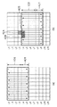
図1により画像をバンドに分割して誤差拡散処理を行う例を説明する。画像100はバンド101、102、103に分割され、バンドの長手方向に直交する方向(図1における上下方向)に画素を交互に走査して誤差拡散処理が行われる。このような走査を行うことで、誤差の拡散が同一方向に偏ることを防ぎ、画質を向上させることができる。
An example of performing error diffusion processing by dividing an image into bands will be described with reference to FIG. The
図2により誤差拡散マトリクスの一例を示す。図2(a)はバンドを下方向に走査する場合の誤差拡散マトリクスで、「*」で示す注目画素の量子化誤差は、次の注目画素(下の画素)に7/16、次列に隣接する三画素に上から3/16、5/16、1/16の比率で拡散される。また、図2(b)はバンドを上方向に走査する場合の誤差拡散マトリクスで、注目画素の量子化誤差は、次の注目画素(上の画素)に7/16、次列に隣接する三画素に上から1/16、5/16、3/16の比率で拡散される。 FIG. 2 shows an example of the error diffusion matrix. FIG. 2 (a) shows an error diffusion matrix when the band is scanned in the downward direction. The quantization error of the target pixel indicated by “*” is 7/16 in the next target pixel (lower pixel) and in the next column. It is diffused at the ratio of 3/16, 5/16, and 1/16 from the top to three adjacent pixels. FIG. 2 (b) shows an error diffusion matrix when the band is scanned upward. The quantization error of the pixel of interest is 7/16 in the next pixel of interest (upper pixel) and three adjacent to the next column. The pixel is diffused at a ratio of 1/16, 5/16, 3/16 from the top.
図3によりオーバラップ領域を設けてバンドの画像を誤差拡散処理する例を説明する。図3(a)に示すように、バンド101の誤差拡散処理において、バンド102に例えば二画素幅分のオーバラップ領域401が設定される。まず、バンド101の左上端(ラインL0の最左端)の画素を注目画素として、下方向に画素を走査し、ラインL5の左端の画素が注目画素になるまで誤差拡散処理を行う。次に、ラインL5の二列目の画素を注目画素として、上方向に画素を走査し、ラインL0の二列目の画素が注目画素になるまで誤差拡散処理を行う。以降、最終列まで交互に走査を繰り返して、バンド101の誤差拡散処理を終了する。バンド101の誤差拡散処理が終了すると、図3(b)に示すように、バンド102と、バンド103の例えば二画素幅分のオーバラップ領域401を処理対象領域として誤差拡散処理を行い、同様の処理を最下端のバンドまで繰り返す。
An example in which an overlap region is provided and error diffusion processing is performed on a band image will be described with reference to FIG. As shown in FIG. 3 (a), in the error diffusion process of the
このような誤差拡散処理を行うと、奇数列の処理において、注目画素の量子化誤差は図2(c)に示す画素eに7/16、画素fに3/16、画素gに5/16、画素hに1/16の比率で拡散される。また、偶数列の処理において、注目画素の量子化誤差は画素dに7/16、画素fに1/16、画素gに5/16、画素hに3/16の比率で拡散される。 When such error diffusion processing is performed, in the odd-numbered column processing, the quantization error of the pixel of interest is 7/16 for pixel e, 3/16 for pixel f, and 5/16 for pixel g shown in FIG. The pixel h is diffused at a ratio of 1/16. Further, in the even column processing, the quantization error of the pixel of interest is diffused at a ratio of 7/16 to the pixel d, 1/16 to the pixel f, 5/16 to the pixel g, and 3/16 to the pixel h.
図3(b)に示すバンド101の境界ラインL3上の偶数列にある注目画素404には、バンド101の誤差拡散処理において、バンド102の境界ラインL4上の画素406、405から誤差が拡散される(以下、拡散誤差A)。バンド102の誤差拡散処理において、画素406、405から注目画素404に(実際には拡散されないが)拡散される誤差(以下、拡散誤差B)がある。ここで、拡散誤差Aの値と拡散誤差Bの値が近似すればドットパターンの不整合は生じない。
In the
バンド101の誤差拡散処理において、画素406、405から注目画素404に実際に拡散される拡散誤差Aは、画素の走査が双方向のため、オーバラップ領域401であるラインL5の量子化誤差の影響を受ける。一方、バンド102の誤差拡散処理において、画素406、405から注目画素404に実際には拡散されない拡散誤差Bは、ラインL5の量子化誤差だけでなく、さらに下方のラインの量子化誤差の影響を受ける。つまり、通常、拡散誤差Aの値と拡散誤差Bの値が近似することはない。特許文献2の発明においては、画素の走査を下方向にのみ行って誤差拡散処理を行うため、このような問題は発生しない。
In the error diffusion process of the
このように、バンドを、その長手方向に直交する方向に双方向に走査して誤差拡散処理を行う場合、オーバラップ領域を設けても、境界部における条状の画質劣化を防ぐことはできない。また、オーバラップ領域を設ければ、その分、メモリの記憶容量を増やす必要があり、計算量も増加するので、実装コストが増加する。 Thus, when performing error diffusion processing by scanning the band bidirectionally in the direction orthogonal to the longitudinal direction, even if an overlap region is provided, strip-shaped image quality deterioration at the boundary cannot be prevented. Further, if the overlap area is provided, it is necessary to increase the storage capacity of the memory, and the amount of calculation increases, so that the mounting cost increases.
本発明は、画像から分割された領域ごとに誤差拡散処理を行う場合の領域の境界における画質劣化を低減することを目的とする。 An object of the present invention is to reduce image quality deterioration at the boundary between regions when error diffusion processing is performed for each region divided from an image.
本発明は、前記の目的を達成する一手段として、以下の構成を備える。 The present invention has the following configuration as one means for achieving the above object.
本発明にかかる画像処理は、複数の領域に分割された画像の領域ごと、画素ごとに誤差拡散処理を行う際に、量子化済みの画素において発生した量子化誤差を保持し、注目画素を含む処理領域における前記走査の方向と前記注目画素の位置に応じて、前記注目画素の近傍の画素を量子化した際に発生した、前記保持する量子化誤差を前記注目画素に拡散するための拡散係数セットを設定し、前記保持する量子化誤差と前記設定した拡散係数セットに基づき、前記近傍の画素それぞれの量子化誤差と当該近傍の画素に対応する拡散係数を乗算し、それら乗算値と前記注目画素の画素値の総和を計算し、前記設定した拡散係数セットを参照する画素位置からの量子化誤差を拡散した前記注目画素を量子化し、前記注目画素が前記処理領域と前記処理領域の処理後に前記誤差拡散処理される未処理領域の境界の近傍に位置する場合、前記拡散係数セットとして、前記未処理領域から伝播されるべき量子化誤差の減少分を前記処理領域内における画素の量子化誤差を用いて補う拡散係数をもつ拡散係数セットを設定することを特徴とする。 The image processing according to the present invention holds a quantization error generated in a quantized pixel when performing error diffusion processing for each pixel and each pixel of an image divided into a plurality of regions, and includes a target pixel. A diffusion coefficient for diffusing the held quantization error to the target pixel, generated when the pixels near the target pixel are quantized according to the scanning direction and the position of the target pixel in the processing region A set is set, and based on the held quantization error and the set diffusion coefficient set, the quantization error of each of the neighboring pixels is multiplied by the diffusion coefficient corresponding to the neighboring pixel, and the multiplication value and the attention calculate the sum of the pixel values of the pixels, and quantizing the pixel of interest by diffusing quantization error from the reference pixel position to a diffusion coefficient set by the setting, the processing the pixel of interest and the treated area When the region is located in the vicinity of the boundary of the unprocessed region that is subjected to the error diffusion processing after the region is processed, the reduction coefficient of the quantization error to be propagated from the unprocessed region is set as the diffusion coefficient set in the pixel in the processing region. A diffusion coefficient set having a diffusion coefficient to be compensated by using the quantization error is set .
本発明によれば、画像から分割された領域ごとに誤差拡散処理を行う場合の領域の境界における画質劣化を低減することができる。 According to the present invention, it is possible to reduce image quality deterioration at the boundary between regions when error diffusion processing is performed for each region divided from an image.
以下、本発明にかかる実施例の画像処理を図面を参照して詳細に説明する。以下では、副走査方向(縦方向)または主走査方向(横方向)の帯状(バンド状)に、画像を複数の領域に分割する。そして、分割した領域ごとに、領域の分割境界に直交する方向に、奇数行または列の画素の走査方向と偶数行または列の画素の走査方向が逆になるように注目画素を走査(以下、往復走査)して誤差拡散処理を行う画像処理を説明する。また、画像は縦横にタイル状またはブロック状に分割することもできる。その場合は、分割した領域ごとに、領域の横または縦方向に往復走査して誤差拡散処理を行う画像処理を説明する。 Hereinafter, image processing according to an embodiment of the present invention will be described in detail with reference to the drawings. In the following, the image is divided into a plurality of regions in a band shape (band shape) in the sub-scanning direction (vertical direction) or the main scanning direction (horizontal direction). Then, for each divided region, the pixel of interest is scanned so that the scanning direction of the odd-numbered rows or columns of pixels and the scanning direction of the even-numbered rows or columns of pixels are reversed in the direction orthogonal to the division boundary of the regions (hereinafter, Image processing for performing error diffusion processing by reciprocating scanning will be described. The image can also be divided vertically and horizontally into tiles or blocks. In this case, image processing for performing error diffusion processing by performing reciprocal scanning in the horizontal or vertical direction of each divided area will be described.
[装置の構成]
図4のブロック図により実施例の画像処理装置の構成例を説明する。画像入力部600は、例えばスキャナであり、原稿画像を読み取ったRGBのアナログ信号をディジタル信号に変換した画像データを出力する。入力データ処理部610は、画像入力部600を制御して、原稿画像を複数の領域に分割した領域ごとに画像データを入力する。入力データメモリ620は、各分割領域の画像データを保持可能な記憶容量のメモリである。
[Device configuration]
A configuration example of the image processing apparatus according to the embodiment will be described with reference to the block diagram of FIG. The
つまり、入力データ処理部610は、入力データメモリ620に各分割領域の画像を展開し、輝度濃度変換、マスキング、下色除去、ガンマ補正などの画像処理を施す。そして、入力データメモリ620に展開した領域に対するハーフトーン処理部625の誤差拡散処理が終了すると、次の分割領域の画像を入力データメモリ620に上書きする。
In other words, the input
ハーフトーン処理部625は、画像出力部680が処理可能な階調数のハーフトーン画像を生成する。例えば、画像出力部680が二階調しか表現できない場合、ハーフトーン処理部625は、連続階調の画像を二値化した二値画像を出力する。
The
ハーフトーン処理部625において、誤差拡散処理部(ED)630は、所定の閾値により入力画像の各画素を量子化し、量子化誤差を計算する。
In the
量子化誤差メモリ640は、量子化誤差を保持する。以下では、各画素の量子化誤差を保持して、処理済みの画素の量子化誤差から計算した拡散誤差と注目画素の値を加算して、注目画素を量子化する方法を説明する。しかし、量子化誤差から計算した拡散誤差を誤差の拡散先の画素ごとに保持して、拡散誤差と注目画素の値を加算して、注目画素を量子化する方法を採用してもよい。
The
領域間の伝播量子化誤差を保持部する誤差バッファ670は、分割領域の内、現在の処理領域(以下、注目領域)に隣接する未処理の、次の処理領域(以下、次領域)に拡散する量子化誤差を保持する。画像出力部680は、例えばインクジェットプリントヘッドを有するプリンタエンジンであり、ハーフトーン処理部625から入力される画像データが表す画像を記録紙に印刷する。
An
つまり、量子化誤差メモリ640は、注目領域の誤差拡散処理において量子化誤差を参照するために量子化誤差を保持する第一のメモリである。また、誤差バッファ670は、次領域の誤差拡散処理において量子化誤差を参照するために量子化誤差を保持する第二のメモリである。
That is, the
拡散係数設定部635の拡散係数メモリ660は、図2(a)(b)に示すような誤差拡散マトリクスを保持する。拡散係数選択部650は、例えば画素の走査方向や注目画素の位置に応じて、拡散係数メモリ660に保持された拡散係数セットから適切な拡散係数セットを選択し、選択した拡散係数セットを誤差拡散処理部630に設定する。
The
拡散係数メモリ660は、図2(a)(b)に示す誤差拡散マトリクスなどに対応する拡散係数セットを保持する。図2(a)(b)に示す誤差拡散マトリクスは注目画素の量子化誤差が拡散される画素(以下、被拡散画素)と、被拡散画素への拡散率を示す。一方、拡散係数メモリ660は、注目画素が被拡散画素の場合に、既に量子化が済んだ画素(以下、拡散元画素)から量子化誤差を加算するための拡散係数セットを保持する。つまり、拡散係数メモリ660が保持する拡散係数セットは、注目画素の近傍の画素を量子化した際の量子化誤差を注目画素に拡散するための誤差拡散マトリクスである。
The
[画像処理]
本実施例の画像処理装置は、図1に示すように、画像を複数のバンド(領域)に分割し、バンドを往復走査して誤差拡散処理を行う。つまり、バンド101の画像が入力データメモリ620に展開され、バンド101の誤差拡散処理が終了すると、バンド102の画像が入力データメモリ620に上書きされる。
[Image processing]
As shown in FIG. 1, the image processing apparatus according to the present embodiment divides an image into a plurality of bands (regions), and performs error diffusion processing by reciprocally scanning the bands. That is, the image of the
バンドの高さ(画素数)は、各バンドで同じ必要はなく、各バンドで異なっていても構わない。言い替えれば、バンドの最大高は、原稿画像の横幅と入力データメモリ620の記憶容量によって決まり、最大高以下であればバンドの高さは任意である。
The band height (number of pixels) need not be the same for each band, and may be different for each band. In other words, the maximum height of the band is determined by the width of the original image and the storage capacity of the
本実施例の画像処理装置は、注目領域の誤差拡散処理で発生した未拡散の量子化誤差を誤差バッファ670に保持して、次領域に拡散させて、バンドの境界においても連続的な誤差拡散処理を行う。
The image processing apparatus according to the present embodiment holds the undiffused quantization error generated in the error diffusion process of the attention area in the
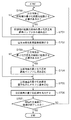
図5のフローチャートにより実施例1の誤差拡散処理を説明する。ED630は、注目画素が、隣接する既に処理が終了した、前の処理領域(以下、前領域)の量子化誤差を拡散する必要がある画素か否かを判定する(S700)。
The error diffusion process of the first embodiment will be described with reference to the flowchart of FIG. The
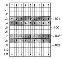
図6により前領域の量子化誤差を拡散する必要がある画素か否かの判定を説明する。注目画素がバンド102の境界ラインL4上の偶数列に位置する場合、注目画素には図2(c)に示す左列の三画素a、b、cと下行の画素eから量子化誤差が拡散される。画素aは、現在入力データメモリ620に展開されたバンド102に含まれないため、誤差バッファ670に保持された画素aの量子化誤差を参照する必要がある。
The determination of whether or not the pixel needs to be diffused with the quantization error in the previous area will be described with reference to FIG. When the target pixel is located in the even column on the boundary line L4 of the
また、注目画素がラインL4上の奇数列に位置する場合、注目画素には左列の三画素a、b、cと上行の画素dから量子化誤差が拡散される。画素a、dは、現在入力データメモリ620に展開されたバンド102に含まれていないため、誤差バッファ670に保持された画素a、dの量子化誤差を参照する必要がある。
Further, when the target pixel is located in an odd column on the line L4, a quantization error is diffused from the three pixels a, b, c in the left column and the pixel d in the upper row to the target pixel. Since the pixels a and d are not currently included in the
このように、図2(a)(b)に示す誤差拡散マトリクスを用いる場合はラインL4上の画素が前領域の量子化誤差を拡散する必要がある画素である。ただし、誤差拡散マトリクスによっては、前領域の量子化誤差を拡散する必要がある画素がラインL4上の画素とは限らない。 As described above, when the error diffusion matrix shown in FIGS. 2A and 2B is used, the pixel on the line L4 is a pixel that needs to diffuse the quantization error of the previous region. However, depending on the error diffusion matrix, the pixel that needs to diffuse the quantization error of the previous region is not necessarily the pixel on the line L4.
ED630は、注目画素が前領域の量子化誤差を拡散する必要がある画素と判定した場合は、誤差バッファ670から前領域の拡散元画素の量子化誤差を読み出す(S701)。そして、注目画素を誤差拡散処理する(S702)。従って、前領域の量子化誤差を拡散する必要があると判定された注目画素は、前領域の拡散元画素の量子化誤差と、量子化誤差メモリ640が保持する注目領域の拡散元画素の量子化誤差を用いて誤差拡散処理される。また、前領域の量子化誤差を拡散する必要がないと判定された注目画素は、量子化誤差メモリ640が保持する注目領域の拡散元画素の量子化誤差を用いて誤差拡散処理される。
When the
次に、ED630は、注目画素が次領域に量子化誤差を拡散する必要がある画素か否かを判定する(S703)。
Next, the
図6において、注目画素がバンド101の境界ラインL3上の偶数列に位置する場合、図2(c)に示す右列の三画素f、g、hと上行の画素dに注目画素の量子化誤差が拡散される。画素hは、現在入力データメモリ620に展開されたバンド101に含まれないため、注目画素の量子化誤差を誤差バッファ670に保持する必要がある。
In FIG. 6, when the pixel of interest is located in an even column on the boundary line L3 of the
また、注目画素がバンド101の境界ラインL3上の奇数列に位置する場合、右列の三画素f、g、hと下行の画素eに注目画素の量子化誤差が拡散される。画素e、hは、現在入力データメモリ620に展開されたバンド101に含まれないため、注目画素の量子化誤差を誤差バッファ670に保持する必要がある。
Further, when the target pixel is located in an odd column on the boundary line L3 of the
このように、図2(a)(b)に示す誤差拡散マトリクスを用いる場合はラインL3上の画素が次領域に量子化誤差を拡散する必要がある画素である。ただし、誤差拡散マトリクスによっては、次領域に量子化誤差を拡散する必要がある画素がラインL3上の画素とは限らない。 As described above, when the error diffusion matrix shown in FIGS. 2A and 2B is used, the pixel on the line L3 is a pixel that needs to diffuse the quantization error to the next region. However, depending on the error diffusion matrix, the pixel that needs to diffuse the quantization error to the next region is not necessarily the pixel on the line L3.
ED630は、注目画素が次領域に量子化誤差を拡散する必要がある画素と判定した場合は、注目画素の量子化誤差を誤差バッファ670に書き込む(S704)。続いて、注目画素の量子化誤差を量子化誤差メモリ640に書き込む(S705)。従って、次領域に量子化誤差を拡散する必要があると判定された注目画素の量子化誤差は、誤差バッファ670および量子化誤差メモリ640に書き込まれる。また、次領域に量子化誤差を拡散する必要がないと判定された注目画素の量子化誤差は、量子化誤差メモリ640に書き込まれる。
If the
次に、ED630は、注目画素の量子化結果を出力する(S706)。そして、入力データメモリ620に展開された領域の全画素の処理が終了したか否かを判定し(S707)、未了であれば処理をステップS700に戻し、ステップS700からS706の処理を繰り返す。
Next, the
[誤差拡散処理]
図7のブロック図により誤差拡散処理部(ED)630の構成例を説明する。図8のフローチャートにより誤差拡散処理部(ED)630による一画素分の誤差拡散処理(S702)を説明する。ED630は、例えば、CMYK各色8ビットの画像データを入力し、CMYK各1ビットの画像データを出力する。
[Error diffusion processing]
A configuration example of the error diffusion processing unit (ED) 630 will be described with reference to the block diagram of FIG. The error diffusion processing (S702) for one pixel by the error diffusion processing unit (ED) 630 will be described with reference to the flowchart of FIG. For example, the
拡散係数選択部650は、注目画素の拡散係数セットを変更する必要があるか否かを判定する(S900)。拡散係数セットを変更する必要がない場合、拡散係数選択部650は、通常の誤差拡散マトリクス(例えば図2(a)または図2(b))に対応する拡散係数セットを拡散係数メモリ660から読み出す。そして、当該拡散係数セットを積和演算器1000に設定する(S901)。また、拡散係数を変更する必要がある場合、拡散係数選択部650は、拡散係数メモリ660から読み出した後述する拡散係数セットを積和演算器1000に設定する(S902)。
The diffusion
領域分割によって、次領域から注目領域へ伝播(拡散)される量子化誤差がなくなる。従って、図2(a)(b)に示す誤差拡散マトリクスを用いる場合、図6に示す境界ラインL3やL7上の画素に拡散される量子化誤差は減少する。図9により量子化誤差の拡散量を説明する。 By dividing the region, there is no quantization error propagated (diffused) from the next region to the region of interest. Therefore, when the error diffusion matrix shown in FIGS. 2 (a) and 2 (b) is used, the quantization error diffused to the pixels on the boundary lines L3 and L7 shown in FIG. 6 is reduced. The amount of quantization error diffusion will be described with reference to FIG.
図9(a)は偶数列の注目画素に拡散される量子化誤差を示し、左列の三画素a、b、cと下行の画素eからそれぞれ1/16、5/16、3/16、7/16の比率で量子化誤差が拡散される。図9(b)は境界ライン上の偶数列の注目画素に拡散される量子化誤差を示し、左列の二画素a、bからそれぞれ1/16、5/16の比率で量子化誤差が拡散される。図9(c)は奇数列の注目画素に拡散される量子化誤差を示し、左列の三画素a、b、cと上行の画素dからそれぞれ3/16、5/16、1/16、7/16の比率で量子化誤差が拡散される。図9(d)は境界ライン上の奇数列の注目画素に拡散される量子化誤差を示し、左列の二画素a、bと上行の画素dからそれぞれ3/16、5/16、7/16の比率で量子化誤差が拡散される。なお、各領域の一列目の境界ライン上の画素は、左列に画素が存在せず、上行の画素dから量子化誤差が拡散されるだけであり、拡散される量子化誤差が減少することはない。 FIG. 9 (a) shows the quantization error diffused to the target pixel in the even-numbered column, from the three pixels a, b, c in the left column and the pixel e in the lower row, 1/16, 5/16, 3/16, The quantization error is diffused at a ratio of 7/16. Fig. 9 (b) shows the quantization error diffused to the target pixel in the even column on the boundary line, and the quantization error is diffused from the two pixels a and b in the left column at a ratio of 1/16 and 5/16, respectively. Is done. FIG. 9 (c) shows the quantization error diffused to the pixel of interest in the odd column, from the three pixels a, b, c in the left column and the pixel d in the upper row, 3/16, 5/16, 1/16, The quantization error is diffused at a ratio of 7/16. FIG. 9 (d) shows the quantization error diffused to the odd-numbered pixels of interest on the boundary line, and 3/16, 5/16, 7 / from the two pixels a and b in the left column and the pixel d in the upper row, respectively. The quantization error is diffused at a ratio of 16. It should be noted that the pixels on the boundary line in the first column of each region have no pixels in the left column, only the quantization error is diffused from the pixel d in the upper row, and the diffused quantization error is reduced. There is no.
つまり、境界ライン上には拡散される量子化誤差がかなり減少する偶数列の画素(以下、激減画素)と、拡散される量子化誤差は僅かに減少する(一列目を除く)奇数列の画素(以下、微減画素)が存在する。ただし、通常使用する誤差拡散マトリクスによっては、激減画素、微減画素が境界ライン上の偶数列、奇数列の画素とは限らない。 In other words, on the boundary line, even-numbered pixels in which the diffused quantization error is considerably reduced (hereinafter, drastically reduced pixels) and diffused quantization errors are slightly reduced (except for the first row) in the odd-numbered pixels. (Hereinafter referred to as a slightly reduced pixel). However, depending on the normally used error diffusion matrix, the drastically reduced pixels and the slightly reduced pixels are not necessarily the pixels in the even and odd columns on the boundary line.
そこで、激減画素、微減画素に対して、それを補正する拡散係数セットを用意する。激減画素が境界ライン上の偶数列の画素とすると、上述したように、その拡散元画素は左列の画素a、bである。従って、画素a、bから拡散される量子化誤差を大きくするために、画素a、bの量子化誤差に乗算する拡散係数を大きくして(例えば、1/16→6/16、5/16→10/16など)、拡散される量子化誤差の減少を補う。 Therefore, a diffusion coefficient set for correcting the sharply reduced pixels and the slightly reduced pixels is prepared. Assuming that the drastically reduced pixels are even-numbered columns on the boundary line, the diffusion source pixels are the left-side pixels a and b as described above. Therefore, in order to increase the quantization error diffused from the pixels a and b, the diffusion coefficient multiplied by the quantization error of the pixels a and b is increased (for example, 1/16 → 6/16, 5/16 → 10/16) to compensate for the reduction of diffused quantization error.
また、微減画素が境界ライン上の奇数列の画素とすると、上述したように、その拡散元画素は左列の画素a、bと上行の画素dである。しかし、画素cからの1/16が減少するだけであるから、すべての拡散元画素に対応する拡散係数を大きくする必要はない。そこで、例えば、画素bから拡散される量子化誤差を大きくするために、画素bの量子化誤差に乗算する拡散係数を大きくして(例えば5/16→6/16など)、拡散される量子化誤差の減少を補う。 Further, if the slightly reduced pixels are the pixels in the odd columns on the boundary line, the diffusion source pixels are the pixels a and b in the left column and the pixels d in the upper row as described above. However, since 1/16 from the pixel c only decreases, it is not necessary to increase the diffusion coefficient corresponding to all the diffusion source pixels. Therefore, for example, in order to increase the quantization error diffused from the pixel b, the diffusion coefficient multiplied by the quantization error of the pixel b is increased (for example, 5/16 → 6/16, etc.), and the quantum to be diffused is increased. Compensate for reduction in conversion error.
積和演算器1000は、誤差バッファ670および量子化誤差メモリ640、または、量子化誤差メモリ640から読み出した各画素の量子化誤差と、各画素に対応する拡散係数を乗算し、各乗算値と注目画素の値の総和を計算する(S903)。量子化器1010は、積和演算器1000の出力を所定の閾値によって量子化して、注目画素の量子化結果を出力する(S904)。逆量子化器1020は、注目画素の量子化結果を逆量子化する(S905)。減算器1030は、積和演算器1000の出力から逆量子化器1020の出力を減算した差分を注目画素の量子化誤差として出力する(S906)。上述したように、量子化誤差は量子化誤差メモリ640に格納され、必要に応じて、誤差バッファ670に格納される。
The product-
このように、分割領域を往復走査して誤差拡散処理する場合、注目領域の誤差拡散処理において前領域の量子化誤差を参照可能にするために誤差バッファ670を設ける。さらに、量子化誤差の拡散量が減少する画素に対しては、拡散量の減少を補うように拡散係数セットを設定する。従って、分割領域を往復走査して誤差拡散処理を行う場合に、オーバラップ領域を設けることなく、前述した拡散誤差Aの値と拡散誤差Bの値を近似させてドットパターンの不整合を防ぐことができる。
As described above, when error diffusion processing is performed by reciprocating scanning of the divided region, the
以下、本発明にかかる実施例2の画像処理を説明する。なお、実施例2において、実施例1と略同様の構成については、同一符号を付して、その詳細説明を省略する。 The image processing according to the second embodiment of the present invention will be described below. Note that the same reference numerals in the second embodiment denote the same parts as in the first embodiment, and a detailed description thereof will be omitted.
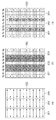
図10により実施例2における領域分割を説明する。実施例1においては、図1に示すように、縦長の画像100を横方向(主走査方向)に分割した各領域を往復走査して誤差拡散処理する例を説明した。実施例2においては、図10(a)に示すように、縦長の画像100を縦方向(副走査方向)に分割した各領域を、領域201、202、203の順に往復走査して誤差拡散処理する例を説明する。実施例2と実施例1は、領域の分割方法と画素の走査方向が異なる点を除いて、同一の処理になる。
The area division in the second embodiment will be described with reference to FIG. In the first embodiment, as shown in FIG. 1, an example in which error diffusion processing is performed by reciprocally scanning each region obtained by dividing a vertically
図11により誤差拡散マトリクスの一例および量子化誤差の拡散量を説明する。図11(a)は領域を右方向に走査する場合の誤差拡散マトリクス、図11(b)は領域を左方向に走査する場合の誤差拡散マトリクスである。 An example of the error diffusion matrix and the amount of quantization error diffusion will be described with reference to FIG. FIG. 11A shows an error diffusion matrix when the region is scanned rightward, and FIG. 11B shows an error diffusion matrix when the region is scanned leftward.
図10(b)において、列R3、R6上に位置する画素は前領域の量子化誤差を拡散する必要がある画素である。従って、領域201、202の誤差拡散処理において、列R2、R5上の画素の量子化誤差を誤差バッファ670に格納する。
In FIG. 10B, the pixels located on the columns R3 and R6 are pixels that need to diffuse the quantization error of the previous region. Accordingly, in the error diffusion processing of the
図10(c)において、境界列R2、R5に位置する画素の量子化誤差の拡散量が減少する。図11(d)から図11(g)に示すように、境界列において、右から左の走査が行われる偶数行の画素は激減画素である。また、境界列において、左から右に走査が行われる奇数行の画素は微減画素である。なお、各領域の一行目の境界列上の画素は、上列に画素が存在せず、左行の画素から量子化誤差が拡散されるだけであり、拡散される量子化誤差が減少することはない。 In FIG. 10 (c), the amount of quantization error diffusion of the pixels located in the boundary rows R2 and R5 decreases. As shown in FIGS. 11 (d) to 11 (g), the pixels in the even-numbered rows that are scanned from the right to the left in the boundary column are drastically reduced pixels. In the boundary column, the pixels in the odd-numbered rows that are scanned from left to right are slightly reduced pixels. In addition, the pixel on the boundary column in the first row of each region has no pixel in the upper column, only the quantization error is diffused from the pixel in the left row, and the diffused quantization error is reduced. There is no.
激減画素が境界列上の偶数行の画素とすると、図11(c)に示すように、その拡散元画素は上行の画素a、dである。従って、画素a、dから拡散される量子化誤差を大きくするために、画素a、dの量子化誤差に乗算する拡散係数を大きくして(例えば、1/16→6/16、5/16→10/16など)、拡散される量子化誤差の減少を補う。 If the drastically reduced pixels are pixels in even rows on the boundary column, the diffusion source pixels are the pixels a and d in the upper row, as shown in FIG. 11 (c). Therefore, in order to increase the quantization error diffused from the pixels a and d, the diffusion coefficient multiplied by the quantization error of the pixels a and d is increased (for example, 1/16 → 6/16, 5/16 → 10/16) to compensate for the reduction of diffused quantization error.
また、微減画素が境界列上の奇数行の画素とすると、その拡散元画素は左列の画素bと上行の画素a、dである。しかし、画素fからの1/16が減少するだけであるから、すべての拡散元画素に対応する拡散係数を大きくする必要はない。そこで、例えば、画素dから拡散される量子化誤差を大きくするために、画素dの量子化誤差に乗算する拡散係数を大きくして(例えば5/16→6/16など)、拡散される量子化誤差の減少を補う。 Further, if the slightly reduced pixels are pixels in odd rows on the boundary column, the diffusion source pixels are the pixel b in the left column and the pixels a and d in the upper row. However, since 1/16 from the pixel f only decreases, it is not necessary to increase the diffusion coefficient corresponding to all the diffusion source pixels. Therefore, for example, in order to increase the quantization error diffused from the pixel d, the diffusion coefficient multiplied by the quantization error of the pixel d is increased (for example, 5/16 → 6/16, etc.), and the quantum to be diffused is increased. Compensate for reduction in conversion error.
以下、本発明にかかる実施例3の画像処理を説明する。なお、実施例3において、実施例1、2と略同様の構成については、同一符号を付して、その詳細説明を省略する。 Hereinafter, image processing according to the third embodiment of the present invention will be described. Note that the same reference numerals in the third embodiment denote the same parts as in the first and second embodiments, and a detailed description thereof will be omitted.
図12により実施例3における領域分割を説明する。実施例1、2においては、図1、図10に示すように、画像をバンド状の領域に分割する例を説明した。実施例3においては、図12(a)に示すように、画像100をタイル状に分割した各領域を、領域301、302、…、306の順に縦方向に往復走査して誤差拡散処理する例を説明する。実施例3と実施例1は、領域の分割方法が異なる点を除いて、同一の画像処理になる。
The area division in the third embodiment will be described with reference to FIG. In the first and second embodiments, the example in which the image is divided into band-shaped regions as illustrated in FIGS. 1 and 10 has been described. In the third embodiment, as shown in FIG. 12A, an error diffusion process is performed by reciprocally scanning each region obtained by dividing the
図12(b)において、列R4、ラインL4、L8上に位置する画素は既に処理が済んだ領域(以下、既処理領域)の量子化誤差を拡散する必要がある画素である。従って、領域301、302、303、304、305の誤差拡散処理において、列R3、ラインL3、L7上の画素の量子化誤差を注目領域の処理後に処理する領域(以下、未処理領域)の誤差拡散処理において参照するために誤差バッファ670に格納する。
In FIG. 12 (b), the pixels located on the column R4 and the lines L4 and L8 are pixels that need to diffuse the quantization error of an already processed region (hereinafter, already processed region). Therefore, in the error diffusion processing of the
図12(c)において、境界ラインL3、L7に位置する(一列目を除く)画素は量子化誤差の拡散量が減少する。図9(a)から図9(d)に示すように、境界ラインにおいて、偶数列の画素は激減画素である。また、境界ラインにおいて、奇数列の画素は微減画素である。激減画素、微減画素に対して、それを補正する拡散係数セットは実施例1と同様に用意すればよい。 In FIG. 12 (c), the amount of quantization error diffusion decreases in the pixels located on the boundary lines L3 and L7 (except for the first column). As shown in FIGS. 9 (a) to 9 (d), the pixels in the even-numbered columns in the boundary line are drastically reduced pixels. In the boundary line, the odd-numbered columns of pixels are slightly reduced pixels. A diffusion coefficient set for correcting the sharply reduced pixels and the slightly reduced pixels may be prepared as in the first embodiment.
以下、本発明にかかる実施例4の画像処理を説明する。なお、実施例4において、実施例1から3と略同様の構成については、同一符号を付して、その詳細説明を省略する。 Hereinafter, image processing according to the fourth embodiment of the present invention will be described. Note that the same reference numerals in the fourth embodiment denote the same parts as in the first to third embodiments, and a detailed description thereof will be omitted.
図13により実施例4における領域分割を説明する。実施例3においては、タイル状に分割した各領域を縦方向に往復走査して誤差拡散処理する例を説明した。実施例4においては、図13(a)に示すように、画像100をタイル状に分割した各領域を、領域501、502、…、506の順に横方向に往復走査して誤差拡散処理する例を説明する。実施例4と実施例1は、領域の分割方法が異なる点を除いて、同一の画像処理になる。
The area division in the fourth embodiment will be described with reference to FIG. In the third embodiment, an example in which error diffusion processing is performed by reciprocally scanning each region divided into tiles in the vertical direction has been described. In the fourth embodiment, as shown in FIG. 13 (a), each region obtained by dividing the
図13(b)において、列R4、ラインL4、L8上に位置する画素は既処理領域の量子化誤差を拡散する必要がある画素である。従って、領域501、502、503、504、505の誤差拡散処理において、列R3、ラインL3、L7上の画素の量子化誤差を未処理領域の誤差拡散処理において参照するために誤差バッファ670に格納する。
In FIG. 13 (b), pixels located on the column R4 and the lines L4 and L8 are pixels that need to diffuse the quantization error of the processed region. Therefore, in the error diffusion processing of the
図13(c)において、境界ラインR3に位置する(一行目を除く)画素は量子化誤差の拡散量が減少する。図11(d)から図11(g)に示すように、境界列において、偶数ラインの画素は激減画素である。また、境界列において、奇数ラインの画素は微減画素である。激減画素、微減画素に対して、それを補正する拡散係数セットは実施例2と同様に用意すればよい。 In FIG. 13 (c), the diffusion amount of the quantization error is reduced in the pixel located on the boundary line R3 (except for the first row). As shown in FIG. 11 (d) to FIG. 11 (g), the pixels on the even lines in the boundary column are drastically reduced pixels. In the boundary column, the pixels on the odd lines are slightly reduced pixels. A diffusion coefficient set for correcting the sharply decreased pixels and the slightly decreased pixels may be prepared as in the second embodiment.
[その他の実施例]
また、本発明は、以下の処理を実行することによっても実現される。即ち、上述した実施形態の機能を実現するソフトウェア(プログラム)を、ネットワーク又は各種記憶媒体を介してシステム或いは装置に供給し、そのシステムあるいは装置のコンピュータ(又はCPUやMPU等)がプログラムを読み出して実行する処理である。
[Other Examples]
The present invention can also be realized by executing the following processing. That is, software (program) that realizes the functions of the above-described embodiments is supplied to a system or apparatus via a network or various storage media, and a computer (or CPU, MPU, etc.) of the system or apparatus reads the program. It is a process to be executed.
Claims (10)
量子化済みの画素において発生した量子化誤差を保持する保持手段と、
注目画素を含む処理領域における前記注目画素の位置に応じて、前記注目画素の近傍の画素を量子化した際に発生した、前記保持手段が保持する量子化誤差を前記注目画素に拡散するための拡散係数セットを設定する設定手段と、
前記保持された量子化誤差と前記設定された拡散係数セットに基づき、前記近傍の画素それぞれに対応する量子化誤差と拡散係数を乗算し、それら乗算値と前記注目画素の画素値の総和を計算する計算手段と、
前記設定された拡散係数セットを参照する画素位置からの量子化誤差を拡散した前記注目画素を量子化する量子化手段とを有し、
前記設定手段は、前記注目画素が前記処理領域と前記処理領域の処理後に前記誤差拡散処理される未処理領域の境界の近傍に位置する場合、前記拡散係数セットとして、前記未処理領域から伝播されるべき量子化誤差の減少分を前記処理領域内における画素の量子化誤差を用いて補う拡散係数をもつ拡散係数セットを設定することを特徴とする画像処理装置。 An image processing apparatus that performs error diffusion processing for each pixel and each pixel of an image divided into a plurality of regions,
Holding means for holding a quantization error generated in the quantized pixel;
A method for diffusing a quantization error held by the holding unit, which is generated when a pixel in the vicinity of the pixel of interest is quantized, according to a position of the pixel of interest in a processing region including the pixel of interest, to the pixel of interest. A setting means for setting a diffusion coefficient set;
Based on the held quantization error and the set diffusion coefficient set, the quantization error and the diffusion coefficient corresponding to each of the neighboring pixels are multiplied, and the sum of the multiplication value and the pixel value of the target pixel is calculated. Calculation means to
The target pixel diffused quantization error from a pixel position reference to the set spreading factor set have a quantizing means for quantizing,
The setting means is propagated from the unprocessed area as the diffusion coefficient set when the target pixel is located in the vicinity of a boundary between the process area and the unprocessed area to be subjected to the error diffusion process after the processing of the process area. An image processing apparatus comprising: a diffusion coefficient set having a diffusion coefficient that compensates for a reduction in quantization error to be compensated by using a pixel quantization error in the processing region .
量子化済みの画素において発生した量子化誤差を保持し、
注目画素を含む処理領域における前記走査の方向と前記注目画素の位置に応じて、前記注目画素の近傍の画素を量子化した際に発生した、前記保持する量子化誤差を前記注目画素に拡散するための拡散係数セットを設定し、
前記保持する量子化誤差と前記設定した拡散係数セットに基づき、前記近傍の画素それぞれに対応する量子化誤差と拡散係数を乗算し、それら乗算値と前記注目画素の画素値の総和を計算し、
前記設定した拡散係数セットを参照する画素位置からの量子化誤差を拡散した前記注目画素を量子化し、
前記注目画素が前記処理領域と前記処理領域の処理後に前記誤差拡散処理される未処理領域の境界の近傍に位置する場合、前記拡散係数セットとして、前記未処理領域から伝播されるべき量子化誤差の減少分を前記処理領域内における画素の量子化誤差を用いて補う拡散係数をもつ拡散係数セットを設定する画像処理方法。 An image processing method for performing error diffusion processing for each pixel and each pixel of an image divided into a plurality of regions,
Holds the quantization error generated in the quantized pixel,
The held quantization error generated when the pixels near the target pixel are quantized is diffused to the target pixel according to the scanning direction and the position of the target pixel in the processing region including the target pixel. Set the diffusion coefficient set for
Based on the quantization error to be held and the set diffusion coefficient set, multiply the quantization error and the diffusion coefficient corresponding to each of the neighboring pixels, calculate the sum of the multiplication value and the pixel value of the pixel of interest,
Quantizing the pixel of interest that has diffused the quantization error from the pixel position referring to the set diffusion coefficient set ,
When the target pixel is located in the vicinity of the boundary between the processing region and the unprocessed region that is subjected to the error diffusion processing after the processing of the processing region, the quantization error to be propagated from the unprocessed region as the diffusion coefficient set An image processing method for setting a diffusion coefficient set having a diffusion coefficient that compensates for a decrease in the number of pixels using a quantization error of pixels in the processing region .
Priority Applications (2)
| Application Number | Priority Date | Filing Date | Title |
|---|---|---|---|
| JP2010188747A JP5641822B2 (en) | 2010-08-25 | 2010-08-25 | Image processing apparatus and method |
| US13/188,221 US8885221B2 (en) | 2010-08-25 | 2011-07-21 | Image processing apparatus and method thereof |
Applications Claiming Priority (1)
| Application Number | Priority Date | Filing Date | Title |
|---|---|---|---|
| JP2010188747A JP5641822B2 (en) | 2010-08-25 | 2010-08-25 | Image processing apparatus and method |
Publications (3)
| Publication Number | Publication Date |
|---|---|
| JP2012049718A JP2012049718A (en) | 2012-03-08 |
| JP2012049718A5 JP2012049718A5 (en) | 2013-09-12 |
| JP5641822B2 true JP5641822B2 (en) | 2014-12-17 |
Family
ID=45696907
Family Applications (1)
| Application Number | Title | Priority Date | Filing Date |
|---|---|---|---|
| JP2010188747A Expired - Fee Related JP5641822B2 (en) | 2010-08-25 | 2010-08-25 | Image processing apparatus and method |
Country Status (2)
| Country | Link |
|---|---|
| US (1) | US8885221B2 (en) |
| JP (1) | JP5641822B2 (en) |
Families Citing this family (5)
| Publication number | Priority date | Publication date | Assignee | Title |
|---|---|---|---|---|
| US8848251B2 (en) * | 2013-01-30 | 2014-09-30 | Hewlett-Packard Development Company, L.P. | Halftoning printing with a page-wide-array printer |
| TWI558211B (en) * | 2015-11-19 | 2016-11-11 | 晶相光電股份有限公司 | Image processing method and device |
| JP6423823B2 (en) * | 2016-06-28 | 2018-11-14 | 京セラ株式会社 | Control apparatus and control method |
| JP7095545B2 (en) * | 2018-10-15 | 2022-07-05 | セイコーエプソン株式会社 | Image processing equipment, image processing methods, and printing equipment |
| JP7452309B2 (en) * | 2020-07-28 | 2024-03-19 | セイコーエプソン株式会社 | Image processing device and image processing method |
Family Cites Families (25)
| Publication number | Priority date | Publication date | Assignee | Title |
|---|---|---|---|---|
| JPH0691606B2 (en) | 1987-06-11 | 1994-11-14 | キヤノン株式会社 | Image processing method |
| JPH0648850B2 (en) * | 1987-06-11 | 1994-06-22 | キヤノン株式会社 | Image processing method |
| JP2684497B2 (en) | 1992-09-14 | 1997-12-03 | 株式会社平安コーポレーション | Pre-cut processing machine |
| US5621545A (en) * | 1993-12-08 | 1997-04-15 | Motta; Ricardo J. | Image production using color error diffusion |
| JPH08228285A (en) * | 1995-02-21 | 1996-09-03 | Seiko Epson Corp | Method and device for processing image |
| US6330075B1 (en) * | 1995-08-03 | 2001-12-11 | Canon Kabushiki Kaisha | Image processing method and apparatus |
| JPH09135351A (en) * | 1995-11-08 | 1997-05-20 | Brother Ind Ltd | Image processing device |
| US5739917A (en) * | 1996-07-12 | 1998-04-14 | Seiko Epson Corporation | Error-diffusion-type half-toning employing adaptive thresholding for enhanced smoothness |
| US5748785A (en) * | 1996-09-26 | 1998-05-05 | Xerox Corporation | Inter-separation color image processing using error diffusion |
| US6175424B1 (en) * | 1996-12-20 | 2001-01-16 | Canon Kabushiki Kaisha | Image processing apparatus and image processing method |
| KR100222989B1 (en) | 1997-07-04 | 1999-10-01 | 윤종용 | An apparatus and a method of image processing for binarizing scanned image at shuttle scanner |
| JP3912633B2 (en) | 1998-01-23 | 2007-05-09 | ソニー株式会社 | Image processing method and apparatus |
| JP3962508B2 (en) | 1999-08-27 | 2007-08-22 | キヤノン株式会社 | Image processing apparatus and method, and storage medium |
| JP3733826B2 (en) | 2000-03-03 | 2006-01-11 | セイコーエプソン株式会社 | Image processing device |
| US8009327B2 (en) | 2002-07-11 | 2011-08-30 | Canon Kabushiki Kaisha | Method and apparatus for image processing |
| JP4471813B2 (en) | 2004-10-29 | 2010-06-02 | 株式会社リコー | Image processing apparatus, image forming apparatus, and program |
| JP4765635B2 (en) * | 2005-09-15 | 2011-09-07 | セイコーエプソン株式会社 | High quality halftone processing |
| JP4204600B2 (en) | 2006-04-03 | 2009-01-07 | シャープ株式会社 | Image processing apparatus, error diffusion processing method, and program |
| KR100834680B1 (en) | 2006-09-18 | 2008-06-02 | 삼성전자주식회사 | Apparatus and method for improving outputted video and image quality in mobile terminal |
| JP4953789B2 (en) | 2006-12-07 | 2012-06-13 | キヤノン株式会社 | Image processing apparatus, recording apparatus, image processing method, program, and storage medium |
| JP4989378B2 (en) * | 2007-09-03 | 2012-08-01 | キヤノン株式会社 | Image processing method and recording apparatus |
| JP2009303185A (en) * | 2008-06-17 | 2009-12-24 | Canon Inc | Image processing apparatus and method therefor |
| JP5197335B2 (en) * | 2008-12-05 | 2013-05-15 | キヤノン株式会社 | Image forming apparatus and control method thereof, information processing apparatus and control method thereof, program, and storage medium |
| US20100188678A1 (en) | 2009-01-29 | 2010-07-29 | Canon Kabushiki Kaisha | Image processing apparatus, printing apparatus, and image processing method |
| JP5508031B2 (en) * | 2010-01-06 | 2014-05-28 | キヤノン株式会社 | Image processing apparatus and image processing method |
-
2010
- 2010-08-25 JP JP2010188747A patent/JP5641822B2/en not_active Expired - Fee Related
-
2011
- 2011-07-21 US US13/188,221 patent/US8885221B2/en active Active
Also Published As
| Publication number | Publication date |
|---|---|
| JP2012049718A (en) | 2012-03-08 |
| US8885221B2 (en) | 2014-11-11 |
| US20120050814A1 (en) | 2012-03-01 |
Similar Documents
| Publication | Publication Date | Title |
|---|---|---|
| JP5641822B2 (en) | Image processing apparatus and method | |
| US20100171970A1 (en) | Image forming apparatus and image forming method | |
| JPH0715606A (en) | Method and device for making digitized gray-value image into half-tone image | |
| KR101350881B1 (en) | Program, Image Processing Device, and Image Processing Method | |
| JP5797030B2 (en) | Image processing apparatus and method | |
| US10542183B2 (en) | Image processing apparatus and method setting dot arrangements to reduce differences in dispersiveness of dots between overlapping and non-overlapping recording areas | |
| US20050046903A1 (en) | Image processing device, image processing method and image processing program | |
| US10404892B2 (en) | Image forming apparatus for outputting a halftone image and image forming method | |
| JP2014082551A (en) | Image processing apparatus and image processing method | |
| Dagar et al. | High performance computing algorithm applied in floyd steinberg dithering | |
| JP2007265055A (en) | Resolution conversion processing method of binary image | |
| JP4251492B2 (en) | Image processing apparatus, image recording apparatus, program, and recording medium | |
| JP4222187B2 (en) | Image processing apparatus, image processing method, and image processing program | |
| JP4158652B2 (en) | Image processing apparatus, image processing method, and image processing program | |
| JP5093382B2 (en) | Image forming apparatus, image forming method, and image forming program | |
| JP4784353B2 (en) | Image forming apparatus, image forming method, and image forming program | |
| JP4262148B2 (en) | Image processing apparatus and image processing method | |
| JP5950694B2 (en) | Image processing apparatus and control method thereof | |
| JP4222151B2 (en) | Image processing apparatus, image processing method, and image processing program | |
| JP4151520B2 (en) | Image processing apparatus, image processing method, and image processing program | |
| JP2007129559A (en) | Image processor and image processing system | |
| JP2003198841A (en) | Image forming method and image forming apparatus | |
| JP2019110512A (en) | Image forming apparatus, image forming method, and program | |
| JP2005039413A (en) | Image processor, image processing method and program | |
| JP2004166093A (en) | Image processor and image processing method |
Legal Events
| Date | Code | Title | Description |
|---|---|---|---|
| A521 | Written amendment |
Free format text: JAPANESE INTERMEDIATE CODE: A523 Effective date: 20130731 |
|
| A621 | Written request for application examination |
Free format text: JAPANESE INTERMEDIATE CODE: A621 Effective date: 20130731 |
|
| A977 | Report on retrieval |
Free format text: JAPANESE INTERMEDIATE CODE: A971007 Effective date: 20140612 |
|
| A131 | Notification of reasons for refusal |
Free format text: JAPANESE INTERMEDIATE CODE: A131 Effective date: 20140714 |
|
| A521 | Written amendment |
Free format text: JAPANESE INTERMEDIATE CODE: A523 Effective date: 20140910 |
|
| TRDD | Decision of grant or rejection written | ||
| A01 | Written decision to grant a patent or to grant a registration (utility model) |
Free format text: JAPANESE INTERMEDIATE CODE: A01 Effective date: 20140929 |
|
| A61 | First payment of annual fees (during grant procedure) |
Free format text: JAPANESE INTERMEDIATE CODE: A61 Effective date: 20141028 |
|
| LAPS | Cancellation because of no payment of annual fees |