EP1079522A1 - Piezoelectric vibration device - Google Patents
Piezoelectric vibration device Download PDFInfo
- Publication number
- EP1079522A1 EP1079522A1 EP00905290A EP00905290A EP1079522A1 EP 1079522 A1 EP1079522 A1 EP 1079522A1 EP 00905290 A EP00905290 A EP 00905290A EP 00905290 A EP00905290 A EP 00905290A EP 1079522 A1 EP1079522 A1 EP 1079522A1
- Authority
- EP
- European Patent Office
- Prior art keywords
- vibration
- pve
- lowm
- vibration element
- piezoelectric
- Prior art date
- Legal status (The legal status is an assumption and is not a legal conclusion. Google has not performed a legal analysis and makes no representation as to the accuracy of the status listed.)
- Withdrawn
Links
Images



Classifications
-
- H—ELECTRICITY
- H03—ELECTRONIC CIRCUITRY
- H03H—IMPEDANCE NETWORKS, e.g. RESONANT CIRCUITS; RESONATORS
- H03H9/00—Networks comprising electromechanical or electro-acoustic elements; Electromechanical resonators
- H03H9/02—Details
- H03H9/02007—Details of bulk acoustic wave devices
- H03H9/02062—Details relating to the vibration mode
- H03H9/0207—Details relating to the vibration mode the vibration mode being harmonic
-
- H—ELECTRICITY
- H03—ELECTRONIC CIRCUITRY
- H03H—IMPEDANCE NETWORKS, e.g. RESONANT CIRCUITS; RESONATORS
- H03H9/00—Networks comprising electromechanical or electro-acoustic elements; Electromechanical resonators
- H03H9/15—Constructional features of resonators consisting of piezoelectric or electrostrictive material
- H03H9/17—Constructional features of resonators consisting of piezoelectric or electrostrictive material having a single resonator
- H03H9/177—Constructional features of resonators consisting of piezoelectric or electrostrictive material having a single resonator of the energy-trap type
-
- H—ELECTRICITY
- H03—ELECTRONIC CIRCUITRY
- H03H—IMPEDANCE NETWORKS, e.g. RESONANT CIRCUITS; RESONATORS
- H03H9/00—Networks comprising electromechanical or electro-acoustic elements; Electromechanical resonators
- H03H9/46—Filters
- H03H9/54—Filters comprising resonators of piezoelectric or electrostrictive material
- H03H9/56—Monolithic crystal filters
Definitions
- the present invention relates to a piezoelectric vibration element relating to thickness mode such as piezoelectric vibration element and piezoelectric filter in which the overtone mode is the main vibration.
- PVE piezoelectric vibration element
- the frequency region used in such PVE is shifted to the higher frequency side.
- the thickness vibration such as thickness slide direction and thickness longitudinal direction is often employed.
- the resonance frequency of the PVE using the thickness vibration is inversely proportional to the plate thickness of the element, thinning of element plate is indispensable for heightening of frequency.
- the element machining method must be determined in consideration of the mechanical strength of the piezoelectric materials, machining precision such as parallelism of plate thickness and distribution within the plane, and reduction of cost. In an ordinary method, the limit of plate thickness of piezoelectric material is about 50 ⁇ m.
- the upper limit of the vibration frequency is about 70 MHz.
- the overtone mode is obtained, that is, the wavelength in the thickness direction is (2n+1) times (n being a natural number) of the lowest order wave mode (hereinafter simply referred to as LOWM).
- the LOWM is often the first-order mode usually having a half wavelength in the thickness direction.
- the polarized inverted layer forming technique of lithium niobate is disclosed in Japanese Laid-open Patent No. 63-311808, and the direct bonding technique of piezoelectric single crystal substrate is disclosed in "Variable Property Crystal Resonators by Direct Bonding Techniques" in IEEE Ultrasonics Symposium, pp. 897-900, 1996.
- the LOWM may be a second-order mode having one wavelength in the thickness direction. That is, when the LOWM is first-order, the overtone mode is third-order, fifth-order, seventh-order, and so forth. When the LOWM is second-order, the overtone mode is sixth-order, tenth-order, fourteenth-order, and so forth. However, even when the overtone mode is used, there is an LOWM at the low frequency side. Accordingly, if suppression of LOWM is imperfect, the oscillation frequency may jump or other abnormal oscillation may occur in an oscillation circuit using a PVE.
- methods for suppressing the LOWM include:
- the method of suppressing the LOWM by circuit configuration includes the overtone mode oscillation circuit.
- an LC resonance circuit of coil and capacitor is added to the oscillation circuit used in the LOWM.
- this LC resonance circuit it is designed to tune in the mode of a desired order, and oscillate in the overtone mode.
- the same operation is possible in a Colpitts oscillator using transistors.
- the method of suppressing the LOWM by the PVE itself includes a method of selecting such a piezoelectric material that the LOWM is hardly excited as compared with the overtone mode, and a method of suppressing the LOWM by the structure of the vibration element.
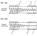
- the vibration energy freely propagates a vibration element 7. Even underneath the excitation electrode, its frequency does not form a stationary wave. However, at a frequency larger than F 0 and smaller than F 0', the vibration energy propagates freely in a certain portion of the excitation electrode 8. In the non-electrode portion, however, the vibration energy attenuates exponentially. Therefore, the vibration displacement is smaller as going toward the PVE end portion. As a result, the vibration energy is concentrated near the excitation electrode. Depending on the piezoelectric material, however, not satisfying the condition of energy confinement of LOWM, the condition of energy confinement is satisfied in the overtone mode.
- the mode to be excited most is the third-order overtone mode having a wavelength of three times in the thickness direction if the LOWM is first-order.
- Such materials include piezoelectric ceramics such as lead titanate material, lithium niobate 36° rotation Y-plate, and lithium niobate Z-plate. Using these materials, the PVE using the thickness longitudinal third-order overtone mode is developed practically. However, even if using a piezoelectric material of which LOWM does not satisfy the condition for energy confinement, a method of utilizing the overtone mode stably is disclosed.
- the vibration displacement of LOWM is large, and the mass of the electrode 9 and others is added to the region in which the vibration displacement of the overtone mode is almost 0, that is, in the periphery of the PVE.
- the vibration displacement of the LOWM is propagated to the outer circumference to leak the vibration energy, thereby suppressing the excitation level of the LOWM.
- the LOWM excitation level is higher than that of the overtone mode. Accordingly, as a method of suppressing the LOWM, it is known to make use of the difference in degree of energy confinement between the LOWM and overtone mode. This is a method of adding an electrode of a certain mass in the PVE peripheral area in the region where the vibration displacement of the LOWM is large and the vibration displacement of the overtone mode is almost 0. In this case, the cut-off frequency of the PVE peripheral area is changed due to oxidation of electrode material or change of interface of electrode film. By this change of cut-off frequency, the PVE by this method is unstable in propagation amount of vibration energy, and lacks in long-term reliability.
- the PVE may induce oscillation frequency jump or other abnormal oscillation.
- the invention is intended to solve the problems of the prior art, and it is hence an object thereof to present a PVE capable of suppressing the LOWM efficiently and allowing to utilize the overtone mode stably if made of a piezoelectric material of which LOWM satisfies the energy confinement condition, and also excellent in long-term reliability because the vibration element part and vibration propagation part are made of same material.
- the PVE of the invention comprises:
- the PVE having such constitution mainly vibrates in the overtone mode of which wavelength in the thickness direction is (2n+1) times (n being a natural number) of LOWM when the LOWM is first-order or second-order.
- the PVE of the invention brings about the following two effects:
- the PVE of the invention is:
- the ratio 2h/H, where h is the depth of the groove in the boundary of the vibration element part and vibration propagation part of the PVE of the invention and H is the thickness of the vibration element part, is defined to be 2/3 or less.
- the main vibration of the PVE of the invention is the thickness slide vibration, and the vibration element part and vibration propagation part are integrated only in the vibration propagation direction.
- the vibration propagation part of the PVE of the invention is formed by applying a vibration-absorbing material on its outer circumference.
- the vibration-absorbing material of the PVE of the invention is a conductive material.
- the vibration propagation part of the PVE of the invention has an upper lid or a lower lid, or both of them.
- the vibration element part of the PVE of the invention has at least a pair of input electrode and output electrode at one side of its principal plane, and a grounding electrode at other principal plane.
- the PVE of the embodiment comprises:
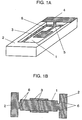
- the vibration element part 1 and vibration propagation part 2 are composed integrally through the groove 6.
- the excitation electrodes 3 are electrically connected to the connection electrode 4 disposed in the vibration propagation part 2 through the external lead-out electrode 5.
- the PVE having such constitution is described below.
- the following example relates to a PVE of which main vibration is the thickness slide vibration, using a crystal AT plate with a plate thickness of 120 ⁇ m in the vibration element part.
- the vibration energy is confined underneath the excitation electrodes 3.
- the degree of attenuation of vibration displacement due to energy confinement depends not only on the size of the excitation electrode 3 but also on the mass of the excitation electrode 3. The greater the mass of the excitation electrode 3, the larger is the attenuation of the vibration displacement.
- the excitation electrode 3 of a large mass becomes a loss component for impeding the vibration.
- the excitation electrode 3 of a large mass is one of the factors for increasing the resonance impedance. Therefore, the excitation electrode 3 is generally formed by applying silver or gold on the PVE principal plane by about hundreds to thousands of angstroms.
- Fig. 2B shows a constitution of PVE not suppressed in the LOWM. This PVE is a completely flat single plate.
- Fig. 2A shows the relative displacement profile of LOWM and third-order overtone mode of the PVE in Fig. 2B.
- Fig. 2A shows the relative displacement profile of LOWM and third-order overtone mode of the PVE in Fig. 2B.
- the axis of abscissas denotes the distance in the vibration propagation direction from the center of the PVE 10
- the axis of ordinates represents the relative displacement supposing the displacement of the LOWM and third-order overtone mode of the PVE 10 in the center to be 1 respectively.
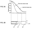
- Fig. 3B shows a PVE having no groove in the boundary of vibration element part 11 and vibration propagation part 12 which are made of same material and are integrated.
- Fig. 3A shows a relative displacement profile of the PVE shown in Fig. 3B.
- the PVE of the structure shown in Fig. 3B has the same effects as the PVE shown in Figs. 10A and 10B in the aspect that the cut-off frequency in the vibration propagation part 12 is decreased.
- the vibration element part 11 and vibration propagation part 12 are made of same material, it is excellent in long-term reliability. As shown in Fig.
- the third-order overtone mode attenuates sufficiently with the relative displacement at the end of the excitation electrode being about 0.04, and the relative displacement of the vibration propagation part 12 in Fig. 3B is nearly equal to 0 in vibration displacement same as in the case of Fig. 2B.
- the LOWM corresponds to the non-electrode portion 11 between the excitation electrode 8 and vibration propagation part 12, and the vibration displacement attenuates.
- the vibration displacement does not attenuate in the vibration propagation part 12, and at the end of the PVE, the relative displacement is about 0.12. Comparing with the relative displacement at the end of the PVE of the LOWM in the case of Fig. 2B, the relative displacement in Fig.
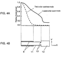
- a groove 13 in the boundary of the vibration element part 11 and vibration propagation part 12 of the PVE in Fig. 3B, a groove 13 of 10 ⁇ m in width and 13 ⁇ m in depth is formed. This groove 13 is formed in both of the face and the back side of the principal plane of the piezoelectric vibrator.
- Fig. 4A shows a relative displacement profile of the PVE in Fig. 4B. The vibration displacement of the third-order overtone mode attenuates sufficiently at the end of the excitation electrode 8, and same as in the PVE in Fig. 2B and Fig.
- the vibration displacement in the vibration propagation part is nearly equal to 0.
- the relative displacement at the end of the piezoelectric vibrator of the LOWM is about 0.12, which is nearly same as in the piezoelectric vibrator in Fig. 3B. Therefore, the vibration energy leak effect of the LOWM seems to be nearly same as in the PVE in Fig. 3B.
- the relative displacement is about 0.17. In the PVE having groove as in Fig. 4B, the relative displacement is 0.36. In the case of the PVE having the groove 13, the relative displacement is about 2 times that without groove 13.
- the vibration of the LOWM not attenuated sufficiently is reflected in the groove area.
- the reflected wave of vibration is an undesired vibration for the resonance of LOWM, which is effective to increase the resonance impedance of the LOWM.
- the size of the displacement of the LOWM at the end of the PVE is almost the same.
- the leak effect of the vibration energy of LOWM to outside is combined with the effect of increasing the resonance impedance of the LOWM as the reflected wave formed in the groove area induces an undesired vibration. Therefore, the PVE shown in Fig. 4B can suppress the LOWM efficiently.
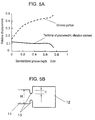
- Fig. 5A shows a relative displacement to the standardized groove depth (2h/H) shown in Fig. 5B.
- the axis of abscissas in Fig. 5A denotes the standardized groove depth (2h/H), and the axis of ordinates represents the relative displacement at the end of the PVE and in the boundary of the vibration element part and vibration propagation part.
- the standardized groove depth (2h/H) of the axis of abscissas is standardized by the plate thickness H of the PVE and the groove depth h.
- the vibration displacement in the boundary of the vibration element part 11 and vibration propagation part 12 is an index for the effect of suppressing the LOWM by the reflected wave. As shown in Fig.
- the vibration displacement in the groove area in the boundary increases as the standardized groove depth 2h/H is larger.
- the vibration displacement at the end of the PVE is an index for the effect of leak of the vibration energy of the LOWM to outside.
- the vibration displacement at the end of the PVE is nearly constant at the standardized groove depth up to about 0.67, but decreases suddenly when exceeding this level. This is because the effective sectional area for propagation of the vibration energy in the vibration propagation part 12 becomes smaller.
- the standardized groove depth 2h/H is preferred to be 2/3 (about 0.67) or less.
- the forming method of the groove 13 includes a mechanical process such as sand blasting.
- a mechanical process such as sand blasting.
- the mechanical strength of the groove 13 may be decreased due to effects of processed degenerated layer.
- a fine groove free from processed degenerated layer may be formed easily.
- a piezoelectric filter in a second embodiment of the invention is described below while referring to the drawings.
- Figs. 6A and 6B are a piezoelectric filter of which main vibration is thickness slide vibration, using a crystal AT plate.
- Fig. 6A shows the appearance of the piezoelectric filter
- Fig. 6B is a sectional view of Fig. 6A.
- This PVE is rectangular in shape.
- the vibration propagation part is not disposed in the width direction so as not to impede the vibration of the overtone mode in the width direction, and is disposed only in the vibration propagation direction.
- the vibration element part 14 and vibration propagation part 15 are made of a same material.
- the piezoelectric filter of the embodiment can absorb the leaking vibration energy efficiently while keeping conduction between the external terminal 23 and the grounding terminal 19.
- the PVE of the embodiment also has the effect of disturbing the resonance of the LOWM and increasing its resonance impedance. Therefore, the piezoelectric filter suppressing the LOWM efficiently and utilizing the stable overtone mode is realized.
- Fig. 7A and Fig. 7B show a PVE of which main vibration is thickness longitudinal vibration, having a structure inverted in the axis of polarization in the center of the thickness direction of lithium niobate Z plate.
- Fig. 7A is an appearance view of the PVE
- Fig. 7B is a sectional view of Fig. 7A.
- the lithium niobate Z plate cannot confine the energy of the first-order mode.
- the LOWM is the second-order mode. Therefore, the energy can be confined. Since the LOWM is the second-order mode, the overtone mode is the sixth-order, tenth-order, fourteenth-order, and so forth.
- the upper lid 28 and lower lid 29 are provided on and under the PVE. Since the thickness of the vibration element part 24 is smaller than that of the vibration propagation part 25, the vibration of the vibration element part 24 will not be impeded. Therefore, the PVE of this embodiment may be put in a package. Moreover, since the vibration propagation part 25 can be utilized as the outer circumference of the package, the PVE can be reduced in size. In particular, the height of the PVE can be lowered.
- the vibration energy propagating to the vibration propagation part 25 is the second-order mode (LOWM). Therefore, if the lids are provided, the overtone mode characteristic is hardly changed.
- the vibration propagation part 25 has the effect of leak of vibration energy of second-order mode to outside. Further, in the groove 26 in the boundary of the vibration element part 24 and vibration propagation part 25, reflection of vibration of LOWM occurs, and undesired vibration takes place. It hence adds an effect of disturbing the resonance of the LOWM and increasing its resonance impedance. As a result, the PVE suppressing the LOWM efficiently and using the stable overtone mode is realized.
- the PVE and piezoelectric filter of the invention have the following two effects:
- the PVE and piezoelectric filter of the invention are:
Landscapes
- Physics & Mathematics (AREA)
- Acoustics & Sound (AREA)
- Chemical & Material Sciences (AREA)
- Crystallography & Structural Chemistry (AREA)
- Piezo-Electric Or Mechanical Vibrators, Or Delay Or Filter Circuits (AREA)
Abstract

Description
- 1
- Vibration element part
- 2
- Vibration propagation part
- 3
- Excitation electrode
- 4
- External connection electrode
- 5
- External lead-out electrode
- 6
- Groove
- 7
- Vibration element
- 8
- Excitation electrode
- 9
- Electrode
- 10
- Piezoelectric vibration element
- 11
- Vibration element part
- 12
- Vibration propagation part
- 13
- Groove
- 14
- Vibration element part
- 15
- Vibration propagation part
- 16
- Groove
- 17
- Input electrode
- 18
- Output electrode
- 19
- Grounding electrode
- 20
- Vibration-absorbing material
- 21
- Fine metal wire
- 22
- Mounting substrate
- 23
- External terminal
- 24
- Vibration element part
- 25
- Vibration propagation part
- 26
- Groove
- 27
- Excitation electrode
- 28
- Upper lid
- 29
- Lower lid
- 30
- External terminal
Claims (8)
- A piezoelectric vibration element comprising a vibration element part, a vibration propagation part made of a same material with a greater thickness than said vibration element part, and a groove disposed in the boundary of said vibration element part and vibration propagation part.
- The piezoelectric vibration element of claim 1, wherein the main vibration is the overtone mode, that is, when the lowest order wave mode is first-order or second-order, the wavelength in the thickness direction is (2n+1) times (n being a natural number) of the lowest order wave mode.
- The piezoelectric vibration element of claim 2, wherein the ratio 2h/H is 2/3 or less where h is the depth of the groove in the boundary of the vibration element part and vibration propagation part and H is the thickness of the vibration element part.
- The piezoelectric vibration element of claim 2, wherein the main vibration is the thickness slide vibration, and the vibration element part and vibration propagation part are integrated only in the vibration propagation direction.
- The piezoelectric vibration element of claim 2, wherein said vibration propagation part has a vibration-absorbing material applied on its outer circumference.
- The piezoelectric vibration element of claim 5, wherein said vibration-absorbing material is a conductive material.
- The piezoelectric vibration element of claim 2, wherein said vibration propagation part has an upper lid or a lower lid, or both of them.
- The piezoelectric vibration element of claim 2, wherein said vibration element part has at least a pair of input electrode and output electrode on its one principal plane, and a grounding electrode on the other principal plane.
Applications Claiming Priority (3)
| Application Number | Priority Date | Filing Date | Title |
|---|---|---|---|
| JP11052186A JP2000252786A (en) | 1999-03-01 | 1999-03-01 | Piezoelectric vibration element |
| JP5218699 | 1999-03-01 | ||
| PCT/JP2000/001031 WO2000052821A1 (en) | 1999-03-01 | 2000-02-23 | Piezoelectric vibration device |
Publications (2)
| Publication Number | Publication Date |
|---|---|
| EP1079522A1 true EP1079522A1 (en) | 2001-02-28 |
| EP1079522A4 EP1079522A4 (en) | 2004-06-09 |
Family
ID=12907786
Family Applications (1)
| Application Number | Title | Priority Date | Filing Date |
|---|---|---|---|
| EP00905290A Withdrawn EP1079522A4 (en) | 1999-03-01 | 2000-02-23 | Piezoelectric vibration device |
Country Status (6)
| Country | Link |
|---|---|
| US (1) | US6518688B1 (en) |
| EP (1) | EP1079522A4 (en) |
| JP (1) | JP2000252786A (en) |
| CN (1) | CN1178384C (en) |
| MY (1) | MY125493A (en) |
| WO (1) | WO2000052821A1 (en) |
Cited By (1)
| Publication number | Priority date | Publication date | Assignee | Title |
|---|---|---|---|---|
| EP2372908A1 (en) * | 2006-08-09 | 2011-10-05 | Epson Toyocom Corporation | At cut quartz crystal resonator element |
Families Citing this family (18)
| Publication number | Priority date | Publication date | Assignee | Title |
|---|---|---|---|---|
| JP2004080711A (en) * | 2002-08-22 | 2004-03-11 | Nippon Dempa Kogyo Co Ltd | Crystal oscillator holding structure |
| KR100488461B1 (en) * | 2003-03-27 | 2005-05-11 | 엘지전자 주식회사 | Laser display device |
| US6903629B1 (en) * | 2003-09-24 | 2005-06-07 | The United States Of America As Represented By The Secretary Of The Army | Electrode-free resonator structures for frequency control, filters and sensors |
| JP2006166390A (en) * | 2004-02-05 | 2006-06-22 | Seiko Epson Corp | Piezoelectric vibrating piece, piezoelectric vibrator and piezoelectric oscillator |
| JP4676286B2 (en) * | 2005-08-31 | 2011-04-27 | 東光株式会社 | Manufacturing method of single plate type piezoelectric bimorph element |
| JPWO2007091417A1 (en) | 2006-02-10 | 2009-07-02 | 株式会社村田製作所 | Vibrator module |
| DE102006047698B4 (en) * | 2006-10-09 | 2009-04-09 | Epcos Ag | Resonant bulk acoustic wave resonator |
| JP5020612B2 (en) * | 2006-12-07 | 2012-09-05 | 日本碍子株式会社 | Piezoelectric thin film device |
| JP5161698B2 (en) * | 2008-08-08 | 2013-03-13 | 太陽誘電株式会社 | Piezoelectric thin film resonator and filter or duplexer using the same |
| CN102498666B (en) * | 2009-09-18 | 2015-10-14 | 株式会社大真空 | Piezoelectric vibrating piece and method for manufacturing piezoelectric vibrating piece |
| JP5471303B2 (en) * | 2009-10-27 | 2014-04-16 | セイコーエプソン株式会社 | Vibrating piece and vibrator |
| US8304968B2 (en) * | 2010-03-17 | 2012-11-06 | Seiko Epson Corporation | Vibrator element, vibrator, oscillator, and electronic apparatus |
| CN202535316U (en) | 2011-03-09 | 2012-11-14 | 精工爱普生株式会社 | Vibrating element, vibrator, oscillator and electronic equipment |
| JP5708089B2 (en) * | 2011-03-18 | 2015-04-30 | セイコーエプソン株式会社 | Piezoelectric vibration element, piezoelectric vibrator, piezoelectric oscillator, and electronic device |
| JP2014075848A (en) * | 2014-01-14 | 2014-04-24 | Seiko Epson Corp | Vibration piece and oscillator |
| JP6390836B2 (en) | 2014-07-31 | 2018-09-19 | セイコーエプソン株式会社 | Vibrating piece, vibrator, vibrating device, oscillator, electronic device, and moving object |
| CN107769751B (en) * | 2016-08-22 | 2023-04-25 | 日本电波工业株式会社 | Crystal oscillator |
| US12615032B2 (en) * | 2024-10-15 | 2026-04-28 | Txc Corporation | Quartz resonator |
Family Cites Families (19)
| Publication number | Priority date | Publication date | Assignee | Title |
|---|---|---|---|---|
| FR2531533A1 (en) * | 1982-08-05 | 1984-02-10 | Flopetrol | PIEZOELECTRIC PRESSURE AND / OR TEMPERATURE SENSOR |
| JPS59128814A (en) * | 1983-01-13 | 1984-07-25 | Nippon Dempa Kogyo Co Ltd | Piezoelectric oscillator |
| JPS613514A (en) | 1984-06-18 | 1986-01-09 | Nippon Dempa Kogyo Co Ltd | Piezoelectric vibrator |
| FR2577362B1 (en) * | 1985-02-13 | 1987-04-17 | Ebauchesfabrik Eta Ag | METHOD FOR MANUFACTURING HIGH FREQUENCY QUARTZ RESONATORS |
| KR920005610B1 (en) * | 1985-04-11 | 1992-07-09 | 도오요오 쓰으신끼 가부시끼가이샤 | Piezo-electric resonator for generating overtones |
| JPH07109971B2 (en) * | 1989-02-20 | 1995-11-22 | 株式会社村田製作所 | Filter device |
| JPH0810811B2 (en) | 1989-03-01 | 1996-01-31 | 東洋通信機株式会社 | Structure of piezoelectric resonator for overtone oscillation |
| JPH06291587A (en) * | 1992-07-08 | 1994-10-18 | Matsushita Electric Ind Co Ltd | Piezoelectric vibrator |
| JPH06291590A (en) * | 1993-03-31 | 1994-10-18 | Citizen Watch Co Ltd | Piezoelectric vibrator and manufacture of the same |
| GB2277228B (en) * | 1993-04-14 | 1996-12-04 | Murata Manfacturing Co Ltd | Vibrator,resonator and resonance component utilizing width expansion mode |
| US5481154A (en) * | 1993-09-28 | 1996-01-02 | Murata Manufacturing Co., Ltd. | Piezo-resonator |
| JPH07212171A (en) * | 1994-01-24 | 1995-08-11 | Meidensha Corp | Thickness-shear crystal oscillator |
| JPH07254839A (en) * | 1994-03-14 | 1995-10-03 | Miyota Kk | Crystal vibrator |
| JPH07321593A (en) * | 1994-05-20 | 1995-12-08 | Citizen Watch Co Ltd | Electrode structure for thickness-shear crystal vibrator |
| JPH084044A (en) * | 1994-06-16 | 1996-01-09 | Hitachi Constr Mach Co Ltd | Work machine interference prevention device |
| JP3223949B2 (en) | 1994-09-13 | 2001-10-29 | 株式会社大真空 | High frequency piezoelectric vibration device |
| JPH08172334A (en) * | 1994-12-20 | 1996-07-02 | Nec Corp | Piezoelectric vibrator |
| JPH09139651A (en) * | 1995-11-15 | 1997-05-27 | Nippon Dempa Kogyo Co Ltd | Crystal unit for overtone |
| JP3731348B2 (en) * | 1998-06-09 | 2006-01-05 | 松下電器産業株式会社 | Piezoelectric vibrator |
-
1999
- 1999-03-01 JP JP11052186A patent/JP2000252786A/en not_active Withdrawn
-
2000
- 2000-02-23 US US09/674,449 patent/US6518688B1/en not_active Expired - Fee Related
- 2000-02-23 CN CNB008002479A patent/CN1178384C/en not_active Expired - Fee Related
- 2000-02-23 EP EP00905290A patent/EP1079522A4/en not_active Withdrawn
- 2000-02-23 WO PCT/JP2000/001031 patent/WO2000052821A1/en not_active Ceased
- 2000-02-25 MY MYPI20000732A patent/MY125493A/en unknown
Cited By (1)
| Publication number | Priority date | Publication date | Assignee | Title |
|---|---|---|---|---|
| EP2372908A1 (en) * | 2006-08-09 | 2011-10-05 | Epson Toyocom Corporation | At cut quartz crystal resonator element |
Also Published As
| Publication number | Publication date |
|---|---|
| MY125493A (en) | 2006-08-30 |
| CN1296664A (en) | 2001-05-23 |
| JP2000252786A (en) | 2000-09-14 |
| US6518688B1 (en) | 2003-02-11 |
| EP1079522A4 (en) | 2004-06-09 |
| WO2000052821A1 (en) | 2000-09-08 |
| CN1178384C (en) | 2004-12-01 |
Similar Documents
| Publication | Publication Date | Title |
|---|---|---|
| US6518688B1 (en) | Piezoelectric vibration device | |
| EP0220320B1 (en) | Piezo-electric resonator for generating overtones | |
| US6215375B1 (en) | Bulk acoustic wave resonator with improved lateral mode suppression | |
| US5925968A (en) | Piezoelectric vibrator, piezoelectric vibrator device having the same and circuit device having the piezoelectric vibrator device | |
| WO1998038736A1 (en) | Piezoelectric vibrator and method for manufacturing the same | |
| JP2001244778A (en) | High-frequency piezoelectric vibrator | |
| US6362561B1 (en) | Piezoelectric vibration device and piezoelectric resonance component | |
| JP5428068B2 (en) | Crystal resonator, crystal unit, and crystal oscillator manufacturing method | |
| JP3102869B2 (en) | Structure of ultra-thin piezoelectric resonator | |
| CN101641863A (en) | Lamb elastic wave element | |
| JP2000040938A (en) | Ultra high frequency piezoelectric device | |
| US6992424B2 (en) | Piezoelectric vibrator ladder-type filter using piezoeletric vibrator and double-mode piezolectric filter | |
| US3544926A (en) | Monolithic crystal filter having mass loading electrode pairs having at least one electrically nonconductive electrode | |
| JP4325178B2 (en) | Piezoelectric vibration element, piezoelectric vibrator and piezoelectric oscillator | |
| KR100496405B1 (en) | Piezoelectric vibrator and filter using the same | |
| US6016025A (en) | Selected overtone resonator with channels | |
| JP4697190B2 (en) | Manufacturing methods for crystal units and crystal units | |
| JP2001339272A (en) | Piezoelectric resonator | |
| JP2025173097A (en) | Vibration element, vibrator, and oscillator | |
| JP2025163410A (en) | Vibration element, vibrator, and oscillator | |
| JP4697190B6 (en) | Manufacturing methods for crystal units and crystal units | |
| JP4697196B2 (en) | Crystal unit and crystal oscillator manufacturing method |
Legal Events
| Date | Code | Title | Description |
|---|---|---|---|
| PUAI | Public reference made under article 153(3) epc to a published international application that has entered the european phase |
Free format text: ORIGINAL CODE: 0009012 |
|
| 17P | Request for examination filed |
Effective date: 20001121 |
|
| AK | Designated contracting states |
Kind code of ref document: A1 Designated state(s): AT BE CH CY DE DK ES FI FR GB GR IE IT LI LU MC NL PT SE |
|
| RBV | Designated contracting states (corrected) |
Designated state(s): DE FR GB |
|
| A4 | Supplementary search report drawn up and despatched |
Effective date: 20040423 |
|
| RIC1 | Information provided on ipc code assigned before grant |
Ipc: 7H 03H 9/05 B Ipc: 7H 03H 9/19 A |
|
| 17Q | First examination report despatched |
Effective date: 20041022 |
|
| 17Q | First examination report despatched |
Effective date: 20041022 |
|
| STAA | Information on the status of an ep patent application or granted ep patent |
Free format text: STATUS: THE APPLICATION IS DEEMED TO BE WITHDRAWN |
|
| 18D | Application deemed to be withdrawn |
Effective date: 20061104 |