EP1079100A2 - Connector arrangement - Google Patents
Connector arrangement Download PDFInfo
- Publication number
- EP1079100A2 EP1079100A2 EP00307350A EP00307350A EP1079100A2 EP 1079100 A2 EP1079100 A2 EP 1079100A2 EP 00307350 A EP00307350 A EP 00307350A EP 00307350 A EP00307350 A EP 00307350A EP 1079100 A2 EP1079100 A2 EP 1079100A2
- Authority
- EP
- European Patent Office
- Prior art keywords
- connector arrangement
- fuel
- high pressure
- pipes
- pressure fuel
- Prior art date
- Legal status (The legal status is an assumption and is not a legal conclusion. Google has not performed a legal analysis and makes no representation as to the accuracy of the status listed.)
- Granted
Links
Images




Classifications
-
- F—MECHANICAL ENGINEERING; LIGHTING; HEATING; WEAPONS; BLASTING
- F02—COMBUSTION ENGINES; HOT-GAS OR COMBUSTION-PRODUCT ENGINE PLANTS
- F02M—SUPPLYING COMBUSTION ENGINES IN GENERAL WITH COMBUSTIBLE MIXTURES OR CONSTITUENTS THEREOF
- F02M55/00—Fuel-injection apparatus characterised by their fuel conduits or their venting means; Arrangements of conduits between fuel tank and pump F02M37/00
- F02M55/004—Joints; Sealings
- F02M55/005—Joints; Sealings for high pressure conduits, e.g. connected to pump outlet or to injector inlet
-
- F—MECHANICAL ENGINEERING; LIGHTING; HEATING; WEAPONS; BLASTING
- F02—COMBUSTION ENGINES; HOT-GAS OR COMBUSTION-PRODUCT ENGINE PLANTS
- F02M—SUPPLYING COMBUSTION ENGINES IN GENERAL WITH COMBUSTIBLE MIXTURES OR CONSTITUENTS THEREOF
- F02M55/00—Fuel-injection apparatus characterised by their fuel conduits or their venting means; Arrangements of conduits between fuel tank and pump F02M37/00
- F02M55/02—Conduits between injection pumps and injectors, e.g. conduits between pump and common-rail or conduits between common-rail and injectors
Definitions
- the invention relates to a connector arrangement for use in a fuel system.
- the invention relates to a connector arrangement whereby a plurality of high pressure fuel pipes can be connected, and sealed, to a housing.
- the invention also relates to a connector arrangement for permitting a plurality of high pressure fuel pipes to be connected to a plurality of fuel injectors in an internal combustion engine.
- a connector arrangement for use in a fuel system, the connector arrangement comprising a bridge member shaped for cooperation with at least first and second members to be connected to a housing, and clamp means for clamping the bridge member to the housing, the bridge member transmitting a clamping load from the clamp means to the first and second members.
- the connector arrangement is suitable for use in an engine.
- the first and second members may both comprise fuel pipes.
- one of the first and second members may comprise a blanking member.
- the housing conveniently comprises an accumulator housing of a fuel pump, the housing being provided with passages whereby, in use, an accumulator chamber located within the accumulator housing communicates with the or at least one of the fuel pipes.
- the housing may comprise a manifold suitable for mounting at an outlet of a fuel pump.
- the clamp means may comprise a bolt which extends through the bridge member and which is in threaded engagement with the housing.
- the clamp means may include a screw-threaded clamp arrangement and a load transmitting member arranged to transmit the clamping load to the bridge member.
- a plurality of bridge members are provided, the load transmitting member transmitting the clamping load to all of the bridge members.
- a connector arrangement comprising a manifold to which a plurality of fuel pipes are permanently mounted.
- the manifold is conveniently adapted to be mounted at an outlet of a fuel pump.
- the fuel pipes may, for example, be brazed or welded to the manifold.
- a connector arrangement for use in a fuel system, the connector arrangement comprising a plurality of high pressure fuel pipes which are supplied with fuel from a common inlet passage, the common inlet being arranged, in use, to receive fuel from a high pressure fuel supply, each of the pipes comprising one or more outlet region which is connectable with an inlet region of a respective injector forming part of the fuel system to permit high pressure fuel to be supplied to said injector.
- the connector is particularly suitable for use in supplying fuel to an internal combustion engine.
- each of the high pressure fuel pipes defines at least one flow passage for fuel between the common inlet passage and the inlet region of an associated injector.
- each of the flow passages for fuel has substantially the same length.
- fuelling consistency between the injectors is improved.
- one or more of the high pressure fuel pipes may be provided with an attachment member for attaching a component to the respective high pressure fuel pipe.
- the attachment member may be used to mount an electrical connector, electrical wiring or a low pressure fuel pipe on the high pressure fuel pipe.
- the connector arrangement according to the third aspect of the present invention can be relatively compact, the connector arrangement may be mounted, in use, under the cam cover of the engine.
- the connector arrangement may comprise two high pressure fuel pipes, each of the pipes defining two flow passages for high pressure fuel, each of the flow passages permitting fuel to be delivered from the high pressure fuel supply to the inlet region of an associated injector.
- the common inlet passage is arranged to communicate with each of the high pressure fuel pipes a part of the way along the length of each of the pipes.
- the connector arrangement may include an inlet member which defines the common inlet passage for fuel.
- the inlet member may be provided with two through bores, each of the bores having a high pressure fuel pipe extending therethrough. As the high pressure pipes extend through the inlet member, the forces on the high pressure pipes are balanced and the pipes are not subjected to undesirable axial forces.
- Each of the high pressure fuel pipes may be provided with a cross drilling to permit communication between the high pressure fuel pipe and the common inlet passage.
- At least one of the high pressure fuel pipes may be provided with a closure member to seal an open end of the respective fuel pipe.
- this embodiment of the invention may be used in an engine having an odd number of injectors.
- the connector arrangement may further comprise a seal assembly for providing a substantially fluid tight seal between the connector arrangement and, for example, the cam cover and/or the engine block of the engine in which the connector arrangement is used.
- a seal assembly for use with a connector arrangement as herein described, the seal assembly comprising a resilient seal member and first and second plate members, the first and second plate members being arranged to apply a force to opposing faces of the seal member such that, upon assembly of the seal assembly, the application of a force to at least one of the plate members serves to deform the seal member into sealing engagement with a surface associated with the fuel system.
- the seal member may be arranged to sealingly engage a surface of a cam cover or engine block of the associated engine.
- the seal member may be provided with a substantially flat surface for engaging a substantially flat surface of the engine block or the cam cover to provide a substantially fluid tight seal.
- the seal member may be arranged to be received within an aperture in the cam cover or the engine block of the engine.
- the connector arrangement may include a further pipe and a further inlet member, the further pipe being arranged to communicate with the common inlet passage and a high pressure fuel supply.
- each end of the further pipe may be arranged to communicate with the common inlet passage of a connector arrangement in accordance with the present invention.
- This embodiment of the invention is particularly suitable for use in "vee" type engines.
- a method of manufacturing a connector arrangement as herein described comprising the steps of;
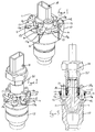
- FIG. 1 illustrates a connector arrangement which comprises an accumulator housing 10 forming part of a fuel pump, the accumulator housing 10 being shaped to define an internal accumulator chamber.
- the accumulator housing 10 is provided with a plurality of passages 11 which communicate with the chamber and which open into outlet ports 12 provided, in the orientation illustrated, at the upper surface of the accumulator housing 10.
- a plurality of fuel pipes 13 are provided, the fuel pipes 13 being adapted, adjacent their end regions, for cooperation with the outlet ports 12 such that the application of a clamping load to the high pressure fuel pipes 13 clamps the pipes 13 to the accumulator housing 10, forming a substantially fluid tight seal between each fuel pipe 13 and the accumulator housing 10 such that the interior of each high pressure fuel pipe 13 communicates with the accumulator chamber.
- Each high pressure fuel pipe 13 includes, adjacent its end, a region 13 a of enlarged diameter, upon which an annular member 14 sits.
- a bridge member 15 is provided, the bridge member 15 being provided with an opening through which a bolt 16 extends, the bolt 16 including a screw-threaded shank which is received, in part, within a screw-threaded bore 17 formed in the accumulator housing 10.
- the bridge member 15 is shaped for cooperation with the annular members 14 of adjacent ones of the fuel pipes 13, each bridge member 15 including, at its opposite ends, a recess 15 a which receives an adjacent part of one of the associated fuel pipes 13.
- the end regions 13 a of the high pressure fuel pipes are located adjacent respective outlet ports 12 of the accumulator housing 10, and the bridge member 15 is located as illustrated in Figure 1 such that the recesses 15 a extend partially around respective ones of the high pressure fuel pipes 13.
- the annular members 14 are trapped between the bridge member 15 and the regions 13 a of the high pressure fuel pipes 13.
- Rotation of the bolt 16 using a suitable tool then takes place to apply a clamping load to the bridge member 15 which, in turn, applies a clamping force to the fuel pipes 13 associated therewith, clamping the fuel pipes 13 to the accumulator housing 10 in such a manner as to form a high pressure seal between each high pressure fuel pipe 13 and the accumulator housing 10.
- the ports 12 are located around the periphery of the upper end of the accumulator housing 10, and space is available for occupation by a pressure sensor arrangement 18 permitting monitoring of the fuel pressure within the accumulator chamber.
- each bridge member 15 is illustrated, it will be appreciated that several such members will be used in practise, each bridge member being used to secure a pair of pipes in position.
- the accumulator housing 10 forms part of a high pressure fuel pump intended for use in a common rail fuel system
- the fuel pipes 13 directly to the accumulator housing 10
- the provision of a separate common rail connected to the outlet of the fuel pump and to which the high pressure fuel pipes would normally be connected can be avoided.
- the common rail fuel system is therefore of reduced complexity and cost.
- the pipes 13 could be connected to an alternative part of the fuel pump.
- FIGS 2 and 3 illustrate an alternative embodiment to that illustrated in Figure 1, and like reference numerals are used to denote like parts.
- the accumulator housing 10 is provided with a central upwardly extending screw-threaded projection 10 a .
- a load transmitting member 19 of generally annular form is located upon the screw-threaded projection 10 a , the load transmitting member 19 being provided with a plurality of outwardly extending arms 19 a which are shaped for cooperation with the bridge members 15 of the arrangement.
- a nut 20 is provided, the nut 20 being in screw-threaded engagement with the projection 10 a .
- the high pressure fuel pipes 13 are located such that the enlarged end regions 13 a cooperate with respective ones of the outlet ports 12, and bridge members 15 are provided between adjacent ones of the high pressure fuel pipes 13.
- the load transmitting member 19 is located upon the projection 10 a such that the arms 19 a of the load transmitting member 19 cooperate with respective ones of the bridge member 15.
- the nut 20 is introduced onto the screw-thread of the projection 10 a and the nut 20 is rotated to apply a suitable clamping load to the load transmitting member 19, and through the bridge members 15 to the high pressure fuel pipes 13.
- the cooperation between the annular members 14 and the enlarged diameter regions 13 a of the fuel pipes 13 conveniently permits the annular members 14 to tilt relative to the fuel pipes 13 thereby ensuring that an even load can be applied to both of the fuel pipes associated with each bridge member 15.
- the upper surface of the load transmitting member 19 and the lower surface of the nut 20 are conveniently of part-spherical or conical form to permit slight tilting of the load transmitting member 19 relative to the nut 20.
- FIG. 2 illustrates the situation where the accumulator housing 10 includes a greater number of outlet ports 12 than required.
- one or more of the outlet ports 12 may be closed by means of a blanking member 13 b which is clamped in position using the bridge member 15 in the manner described hereinbefore, the blanking member 13 b simply replacing one of the high pressure fuel pipes 13.
- the accumulator housing conveniently carries a fuel pressure sensor 18 permitting monitoring of the fuel pressure within the accumulator chamber.
- the manner in which the fuel pressure sensor 18 is mounted may also act as a lock nut preventing or limiting rotation of the nut 20, in use, thereby reducing the risk of one or more of the high pressure fuel pipes 13 being released from the accumulator housing 10, in use.
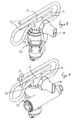
- Figures 4 and 5 illustrate an alternative embodiment in which rather than connecting the high pressure fuel pipes 13 directly to an accumulator housing 10 of a fuel pump, a housing in the form of a manifold 21 is provided, the manifold 21 being mounted upon an outlet of a high pressure fuel pump 22 and having a plurality of outlet ports 12 to which high pressure fuel pipes 13 are connected, for example using the technique illustrated in Figure 1. It will be appreciated, however, that if desired, the arrangement illustrated in Figures 2 and 3 could be used to secure the high pressure fuel pipes to the manifold 21.
- the manifold 21 is conveniently designed to permit the mounting of a fuel pressure sensor 18 thereto.
- the manifold 21 is conveniently mounted upon the accumulator housing 10 of the fuel pump 22 using a nut 23 which cooperates a screw-threaded projection 10 a of the accumulator housing 10, the nut 23 being provided, at its outer periphery, with a groove which receives a snap-ring 24, the snap-ring 24 being received within a similar groove provided in the manifold 21. Rotation of the nut 23 provides a clamping load which is transmitted through the snap-ring 24 to compress a washer 25 located between the manifold 21 and the projection 10 a .
- the angle of the manifold 21 relative to the housing of the fuel pump 10 can be adjusted to any desired angle without affecting the magnitude of the clamping load between the manifold 21 and the accumulator housing 10.
- Figures 6 and 7 illustrate a modification to the arrangement illustrated in Figures 4 and 5 in which rather than using a bridge member 15 and bolt 16 to secure the high pressure fuel pipes 13 to the manifold 21, the high pressure fuel pipes 13 are permanently secured to the manifold 21, for example using a brazing or welding technique.
- the high pressure fuel pipes 13 can pass completely through the manifold 21 such that the axial hydraulic forces applied thereto are balanced.
- cross holes 13b must be drilled in the pipes 13 to permit communication between the interior of the pipes 13 and the passages 11 of the manifold 21.
- the manifold 21 is conveniently arranged to be secured to a high pressure fuel pump 22 using the technique described hereinbefore with reference to Figure 4.
- Figures 8 and 9 illustrate a manifold 21 which is designed to permit four fuel injectors to be connected through the high pressure fuel pipes 13 to the manifold 21 and hence to the fuel pump 22.
- the fuel pump is a single cylinder fuel pump.
- Figures 10 and 11 illustrate the use of the same manifold 21 with a twin cylinder fuel pump, the arrangement of Figure 10 being arranged to feed four fuel injectors, and that of Figure 11 being arranged to feed six fuel injectors. It is apparent from Figures 10 and 11 that, in such arrangements, two such manifolds 21 are provided, each manifold 21 being associated with a corresponding one of the cylinders of the fuel pump.
- FIGs 10 to 13 further illustrate that the fuel pump may be arranged to be driven using a variety of conventional techniques, for example using an Oldham coupling, a conventional conical drive coupling arrangement, or by being driven directly from, for example, an engine cam shaft (see Figure 13).
- the technique described hereinbefore using a snap-ring 24 to couple the manifold 21 to the accumulator housing 10 may be replaced by a simple screw-threaded coupling arrangement, the nut 23 being provided both with an interior screw-thread formation to couple the nut 23 to the projection 10 a , and an outer thread which is either of different pitch or oppositely handed to the thread provided on the interior of the nut 23, the exterior thread being arranged to cooperate with a screw-thread provided on the manifold 21.
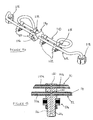
- Figure 14 illustrates a further alternative embodiment of the invention, in which the connector arrangement comprises first and second high pressure fuel pipe 110,112 for supplying fuel under high pressure to a plurality of fuel injectors (not shown) forming part of an engine.
- the connector arrangement also comprises an inlet member 114 which defines a common inlet passage 116 for fuel, the inlet passage 116 communicating with the high pressure fuel pipes 110,112 such that fuel supplied to the inlet passage 116 flows into the fuel pipes 110,112.
- Each of the fuel pipes 110,112 defines two flow passages for fuel, 110 a ,110 b and 112 a ,112 b respectively, each of the flow passages 110 a , 110 b , 112 a , 112 b having an outlet region 118 which communicates, in use, with an inlet region (not shown) of a respective fuel injector.
- the flow passages 110 a , 110 b , 112 a , 112 b communicate with the inlet passage 116 by means of cross drillings 120 provided in the high pressure fuel pipes 110,112.
- the pipes 110,112 are non-linear and are arranged such that each of the flow passages 110 a , 110 b , 112 a , 112 b between the point of communication with a common inlet passage 116 and the respective injector inlet region has substantially the same length. This helps to improve fuelling consistency between the injectors.
- the pipes 110,112 will be provided with bends, the pipe carrying fuel to injectors having a location in the engine closer to the inlet passage 116 being bent by a greater amount than the pipe carrying fuel to the injectors having a location further from the inlet passage 116.
- the connector arrangement may be mounted either above or beneath the cam cover of the associated engine.
- the connector arrangement may also be provided with a plurality of attachment members 122 (only four of which are shown in Figure 14).
- the attachment members 122 may be secured to the pipes 110,112 by any suitable means such as, for example, a clip arrangement.
- the attachment members 122 enable other components within the engine to be attached to the pipes 110,112.
- each of the attachment members 122 may define an aperture for receiving electrical wiring or a low pressure fuel pipe to provide a convenient means of mounting the wiring or the piping within the engine.
- the inlet member 114 is provided with a bore to define the inlet passage 116 and the cross drillings 120 are formed within the pipes 110,112.
- the inlet member 114 is also provided with two through bores into which the high pressure fuel pipes 110,112 are inserted.
- the pipes 110,112 are then secured within the bores of the inlet member by means of a suitable technique.
- the pipes 110,112 may be secured within the bores by means of welding, brazing or by pressuring the pipes such that they expand to form an interference fit within their respective bore.
- the pipes 110,112 extend through the inlet member 114, one end of each pipe projecting through an open end of the respective bore, hydraulic forces on the pipes 110,112 are balanced and the pipes are not subjected to large axial forces.
- the inlet passage 116 provided in the inlet member 114 and the cross drillings 120 provided through the pipes 110,112 may be formed following insertion of the pipes 110,112 through the bores of the inlet member 114.
- the connector arrangement may be provided with a seal assembly, referred to generally as 124, to provide a substantially fluid tight seal between the cam cover and the engine block.
- the seal assembly includes a resilient seal member 126 and first and second plate members 128 a , 128 b , the seal member 126 being located between the first and second plate members 128 a , 128 b and being secured in position by means of a nut 130.
- the seal member 126 and the plate members 128 a , 128 b are provided with an aperture through which the inlet member 114 extends.
- the seal assembly 124 also has a substantially flat lower surface 124 a which is engageable with a surface associated with the cam cover or the engine block of the engine when the connector arrangement is installed in the engine.
- a force is applied to the plate members 128 a , 128 b by tightening the nut 130 such that the seal member 126 is pushed outwardly to sealingly engage the surface of the cam cover or the engine block.
- engagement between the seal member 126 and the cam cover or the engine block also serves to minimise vibration of the inlet member 114 when the engine is in use.
- the seal assembly 124 may be provided with a further aperture 132 for receiving other components within the engine, for example electrical wiring or a low pressure pipe, the internal diameter of the aperture 132 engaging a surface of the component in such a way as to provide a substantially fluid tight seal.
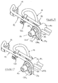
- Figure 17 shows an alternative embodiment of the invention in which like reference numerals are used to denote similar parts to those shown in Figures 14 to 16.
- the seal assembly 124 is shaped to be received within an aperture in either the cam cover or the engine block, as opposed to being provided with a flat surface.
- a force is applied to the plates 128 a , 128 b by tightening the nut 130 to deform the seal member 126 such that a substantially fluid tight seal is provided between the seal member and the aperture within which it is received.
- the inlet member 114 is still provided with two through bores for receiving the pipes 110,112, one open end of the pipe 112 being closed by means of a closure member 134.
- the closure member 134 is received within the pipe 112 to close the open end thereof, rather than engaging the outer surface of the pipe 112. This provides the advantage that hydraulic forces on the closure member 134 are reduced when in use.
- the closure member 134 may be welded, brazed or screwed within the pipe 112. Alternatively, a combination of any of these methods may be used to seal the closure member 134 within the pipe 112.
- Figure 19 shows a further alternative embodiment of the invention comprising two connector arrangements as shown in Figure 18, each arrangement being arranged such that the inlet member 114 thereof receives fuel from a common inlet pipe 136, the inlet pipe 136 receiving fuel from a further pipe 138 in communication with a high pressure fuel supply.
- the arrangement in Figure 19 is particularly suitable for use in a "vee" type engine.
- An inlet member 140 is associated with the pipes 136,138, the inlet member 140 being provided with a through bore through which the pipe 136 extends.
- the pipe 136 is arranged within the inlet member 140 in the same way as the pipes 110,112 are arranged within the inlet member 114.
- the connector arrangement in Figure 19 is suitable for use in an engine having six fuel injectors, each one of the six injectors receiving fuel from one of six outlet regions 118 of the connector arrangement.
- the pipe 138 may be provided with a further member 142 to which a pressure, temperature or other type of sensor may be attached.
- the present invention is suitable for use in an engine having a different number of injectors to that described previously.
- more than two high pressure fuel pipes may be provided through the inlet member 114, each pipe being provided with one or more outlet regions 118 to permit fuel delivery to a respective injector.
Landscapes
- Engineering & Computer Science (AREA)
- Chemical & Material Sciences (AREA)
- Combustion & Propulsion (AREA)
- Mechanical Engineering (AREA)
- General Engineering & Computer Science (AREA)
- Fuel-Injection Apparatus (AREA)
- Non-Disconnectible Joints And Screw-Threaded Joints (AREA)
- Connection Of Plates (AREA)
Abstract
Description
Claims (27)
- A connector arrangement for use in a fuel system, the connector arrangement comprising a bridge member (15) shaped for cooperation with at least first and second members (13) to be connected to a housing (10), and clamp means (16; 19) for clamping the bridge member (15) to the housing (10), the bridge member (15) transmitting a clamping load from the clamp means (16; 19) to the first and second members.
- The connector arrangement as claimed in Claim 1, wherein the first and second members (13) both comprise fuel pipes.
- The connector arrangement as claimed in Claim 1, wherein one of the first and second members (13) comprises a blanking member (13b).
- The connector arrangement as claimed in Claim 2 or Claim 3, wherein the housing comprises an accumulator housing (10) of a fuel pump, the accumulator housing (10) being provided with passages (11) whereby, in use, an accumulator chamber located within the accumulator housing (10) communicates with the or at least one of the fuel pipes.
- The connector arrangement as claimed in Claim 2 or Claim 3, wherein the housing (10) comprises a manifold (21) for mounting at an outlet of a fuel pump (22).
- The connector arrangement as claimed in any of Claims 1 to 5, wherein the clamp means comprise a bolt (16) which extends through the bridge member (15) and which is in threaded engagement with the housing (10).
- The connector arrangement as claimed in any of Claims 1 to 5, wherein the clamp means include a screw-threaded clamp arrangement (20) and a load transmitting member (19) arranged to transmit the clamping load to the bridge member (15).
- The connector arrangement as claimed in Claim 7, comprising a plurality of bridge members (15), the load transmitting member (19) being arranged to transmit the clamping load to all of the bridge members (15).
- A connector arrangement comprising a manifold (21) to which a plurality of fuel pipes (13) are permanently mounted.
- The connector arrangement as claimed in Claim 9, wherein the manifold (21) is adapted to be mounted at an outlet of a fuel pump (22).
- A connector arrangement for use in a fuel system, the connector arrangement comprising a plurality of high pressure fuel pipes (110,112) which are supplied with fuel from a common inlet passage (116), the common inlet passage (116) being arranged, in use, to receive fuel from a high pressure fuel supply, each of the pipes (110, 112) comprising one or more outlet region (118) which is connectable with an inlet region of a respective injector forming part of the fuel system to permit high pressure fuel to be supplied to said injector.
- The connector arrangement as claimed in Claim 11, wherein each of the high pressure fuel pipes (110, 112) defines at least one flow passage (110a, 110b, 112a, 112b) for fuel between the common inlet passage (116) and the inlet region of an associated injector.
- The connector arrangement as claimed in Claim 12, wherein each of the flow passages (110a, 110b, 112a, 112b) for fuel has substantially the same length.
- The connector arrangement as claimed in any of Claims 11 to 13, wherein one or more of the high pressure fuel pipes (110, 112) is provided with an attachment member (122) for attaching a component to the respective high pressure fuel pipe (110, 112).
- The connector arrangement as claimed in any of Claims 11 to 14, wherein the common inlet passage (116) is arranged to communicate with each of the high pressure fuel pipes (110, 112) a part of the way along the length of each of the pipes (110, 112).
- The connector arrangement as claimed in any of Claims 11 to 15, wherein the connector arrangement includes an inlet member (114) which defines the common inlet passage (116) for fuel.
- The connector arrangement as claimed in Claim 16, wherein the inlet member (114) is provided with two through bores, each of the bores having a high pressure fuel pipe (110, 112) extending therethrough.
- The connector arrangement as claimed in any of Claims 11 to 17, including a further pipe (138) and a further inlet member (140), the further pipe (138) being arranged to communicate with the common inlet passage (116) and a high pressure fuel supply.
- The connector arrangement as claimed in Claim 18, wherein each end of the further pipe may (138) is arranged to communicate with the common inlet passage (116) of a further connector arrangement as claimed in any of Claims 11 to 19.
- The connector arrangement as claimed in any of Claims 11 to 19, wherein each of the high pressure fuel pipes (110, 112) is provided with a cross drilling (120) to permit communication between the high pressure fuel pipe (110, 112) and the common inlet passage (116).
- The connector arrangement as claimed in any of Claims 11 to 20, wherein at least one of the high pressure fuel pipes (110, 112) is provided with a closure member (134) to seal an open end of the respective fuel pipe (110, 112).
- The connector arrangement as claimed in any of Claims 11 to 21, for use in an engine having a cam cover and an engine block, the connector arrangement further comprising a seal assembly (124) for providing a substantially fluid tight seal between the connector arrangement and the cam cover and/or the engine block.
- A seal assembly (124) for use with a connector arrangement as claimed in any of Claims 11 to 23, the seal assembly (124) comprising a resilient seal member (126) and first and second plate members (128a, 128b), the first and second plate members (128a, 128b) being arranged to apply a force to opposing faces of the seal member (126) such that, upon assembly of the seal assembly, the application of a force to at least one of the plate members (128a, 128b) serves to deform the seal member (126) into sealing engagement with a surface associated with the fuel system.
- The seal assembly as claimed in Claim 23, for use in an engine having a cam cover and an engine block, the seal member (126) being arranged to sealingly engage a surface of the cam cover or the engine block.
- The seal assembly as claimed in Claim 24, wherein the seal member (126) is provided with a substantially flat surface for engaging a substantially flat surface of the engine block or the cam cover to provide a substantially fluid tight seal.
- The seal assembly as claimed in Claim 24, wherein the seal member (126) is shaped to be received within an aperture provided in the cam cover or the engine block.
- A method of manufacturing a connector arrangement as claimed in any of Claims 11 to 22 comprising the steps of;providing an inlet member (114) with at least one through bore;inserting a pipe (110, 112) for carrying high pressure fuel through the bore in the inlet member (114); andforming an inlet passage (116) through the inlet member (114) such that the inlet passage (116) communicates with a flow passage (110a, 110b, 112a, 112b) defined by the pipe (110, 112) to permit fuel in the inlet passage (116) to be supplied to the flow passage (110a, 110b, 112a, 112b), in use.
Applications Claiming Priority (4)
| Application Number | Priority Date | Filing Date | Title |
|---|---|---|---|
| GBGB9920204.6A GB9920204D0 (en) | 1999-08-27 | 1999-08-27 | Connector arrangement |
| GB9920204 | 1999-08-27 | ||
| GB0000865A GB0000865D0 (en) | 2000-01-15 | 2000-01-15 | Connector arrangement |
| GB0000865 | 2000-01-15 |
Publications (3)
| Publication Number | Publication Date |
|---|---|
| EP1079100A2 true EP1079100A2 (en) | 2001-02-28 |
| EP1079100A3 EP1079100A3 (en) | 2003-11-26 |
| EP1079100B1 EP1079100B1 (en) | 2005-12-21 |
Family
ID=26243405
Family Applications (1)
| Application Number | Title | Priority Date | Filing Date |
|---|---|---|---|
| EP00307350A Expired - Lifetime EP1079100B1 (en) | 1999-08-27 | 2000-08-25 | Connector arrangement |
Country Status (4)
| Country | Link |
|---|---|
| US (1) | US6802539B2 (en) |
| EP (1) | EP1079100B1 (en) |
| AT (1) | ATE313710T1 (en) |
| DE (1) | DE60024938T2 (en) |
Cited By (8)
| Publication number | Priority date | Publication date | Assignee | Title |
|---|---|---|---|---|
| WO2007113038A1 (en) * | 2006-03-30 | 2007-10-11 | Robert Bosch Gmbh | Fuel injection device for a multi-cylinder fuel internal combustion engine |
| EP2187039A3 (en) * | 2005-03-03 | 2010-08-11 | Robert Bosch GmbH | Fuel injection system |
| WO2013098116A1 (en) * | 2011-12-30 | 2013-07-04 | Continental Automotive Gmbh | High pressure pump and system |
| WO2013098119A1 (en) * | 2011-12-30 | 2013-07-04 | Continental Automotive Gmbh | High pressure pump and system |
| WO2013117445A1 (en) * | 2012-02-08 | 2013-08-15 | Robert Bosch Gmbh | A fuel supply device in a vehicle |
| KR20140108589A (en) * | 2011-12-30 | 2014-09-11 | 콘티넨탈 오토모티브 게엠베하 | System for the delivery of a fluid |
| EP2821630A1 (en) * | 2013-07-05 | 2015-01-07 | Delphi International Operations Luxembourg S.à r.l. | High pressure fluid connection |
| CN105658947A (en) * | 2013-07-05 | 2016-06-08 | 德尔福国际运营卢森堡有限公司 | Distributed fuel injection equipment |
Families Citing this family (10)
| Publication number | Priority date | Publication date | Assignee | Title |
|---|---|---|---|---|
| US20070181289A1 (en) * | 2003-11-07 | 2007-08-09 | Ermiro Palmiri | Block manifold for large-sized thermal exchange batteries |
| DE102006017399A1 (en) * | 2006-04-13 | 2007-10-18 | Contitech Techno-Chemie Gmbh | Heated hose line system for exhaust aftertreatment systems of internal combustion engines |
| US20080106095A1 (en) * | 2006-11-08 | 2008-05-08 | Harris Richard K | Heater core connector tube |
| JP4840391B2 (en) * | 2008-03-28 | 2011-12-21 | 株式会社デンソー | Fuel pressure sensor mounting structure and fuel pressure detection system |
| CA2635410C (en) * | 2008-06-19 | 2010-08-17 | Westport Power Inc. | Dual fuel connector |
| US8479709B2 (en) * | 2010-04-27 | 2013-07-09 | Ford Global Technologies, Llc | Automotive line bundling system |
| DE102013219892A1 (en) * | 2013-10-01 | 2015-04-02 | Robert Bosch Gmbh | Holder for fixing a component to an internal combustion engine |
| CN103672266A (en) * | 2013-12-02 | 2014-03-26 | 安徽捷迅光电技术有限公司 | Air distribution pipe for color selector |
| DE102013113925A1 (en) * | 2013-12-12 | 2015-06-18 | Dr. Ing. H.C. F. Porsche Aktiengesellschaft | Fuel line |
| EP3067230A1 (en) * | 2015-03-09 | 2016-09-14 | Magna Steyr Fuel Systems GesmbH | Filling head |
Family Cites Families (37)
| Publication number | Priority date | Publication date | Assignee | Title |
|---|---|---|---|---|
| US1363713A (en) | 1920-07-28 | 1920-12-28 | Locomotive Superheater Co | Means for securing pipes to headers |
| FR598607A (en) | 1924-05-24 | 1925-12-21 | Cie Des Surchauffeurs | Method and coupling device for tubular elements |
| GB330301A (en) | 1929-03-06 | 1930-06-06 | British Thomson Houston Co Ltd | Improvements in or relating to devices for securing the ends of cables to magneto distributors or other apparatus |
| FR700784A (en) | 1929-10-30 | 1931-03-06 | Cie Des Surchauffeurs | Ball joint for high pressure |
| US2892453A (en) * | 1956-12-13 | 1959-06-30 | Bosch Gmbh Robert | Fuel injection systems for multicylinder engines |
| US2937636A (en) * | 1957-03-30 | 1960-05-24 | Bosch Gmbh Robert | Fuel supply system for multi-cylinder internal combustion engines |
| US4357925A (en) * | 1980-12-17 | 1982-11-09 | The Bendix Corporation | Distributor injection pump for diesel engines |
| DE3132432A1 (en) * | 1981-08-17 | 1983-02-24 | Robert Bosch Gmbh, 7000 Stuttgart | FUEL INJECTION SYSTEM |
| US4468054A (en) | 1982-11-03 | 1984-08-28 | The Singer Company | Flange mounted thermostatic expansion valve |
| DE3810385A1 (en) | 1988-03-26 | 1989-03-16 | Daimler Benz Ag | Device for axially securing a plurality of hose plug-in nipples or plug-in line ends |
| JP2694276B2 (en) * | 1988-04-18 | 1997-12-24 | スズキ株式会社 | Fuel supply device |
| DE3825313A1 (en) | 1988-07-26 | 1990-02-01 | Linde Ag | Device for fastening pressure hoses in connection bores |
| US5109822A (en) * | 1989-01-11 | 1992-05-05 | Martin Tiby M | High pressure electronic common-rail fuel injection system for diesel engines |
| JPH0754612Y2 (en) * | 1989-06-06 | 1995-12-18 | 臼井国際産業株式会社 | Fuel delivery pipe |
| US5071172A (en) | 1990-01-09 | 1991-12-10 | Ford Motor Company | Fluid direction tube insertion assembly and insertion method |
| FR2668242B1 (en) | 1990-10-17 | 1993-01-22 | Valeo | FLANGE FOR CONNECTING THE INLET AND OUTLET TUBES OF AN EVAPORATOR. |
| JP3001960B2 (en) * | 1990-11-06 | 2000-01-24 | 臼井国際産業株式会社 | Fluid supply pipe and method of manufacturing the same |
| EP0507191B1 (en) * | 1991-04-04 | 1994-09-21 | Toyota Jidosha Kabushiki Kaisha | A fuel injection device of an engine |
| JP2803383B2 (en) * | 1991-04-08 | 1998-09-24 | トヨタ自動車株式会社 | High pressure fluid fittings |
| DE4115039A1 (en) * | 1991-05-08 | 1992-11-12 | Bosch Gmbh Robert | FUEL DISTRIBUTOR |
| DE4228155C1 (en) | 1992-08-25 | 1993-12-02 | Daimler Benz Ag | Device for fastening at least one exposed line to a fastening body, in particular a fuel filter for an internal combustion engine |
| EP0657678B1 (en) | 1993-12-07 | 1998-09-02 | Smc Corporation | Tube coupling for fluidic apparatus |
| US5390638A (en) | 1994-02-25 | 1995-02-21 | Siemens Automotive L.P. | Fuel rail assembly |
| US5695225A (en) | 1995-05-08 | 1997-12-09 | Spinco Metal Products, Inc. | Reusable union coupling |
| JP2937081B2 (en) * | 1995-06-26 | 1999-08-23 | いすゞ自動車株式会社 | Fuel injection nozzle tightening device |
| AU1568097A (en) | 1995-12-22 | 1997-07-17 | Kelsey-Hayes Company | Quick-connect arrangement for high density hydraulic lines for anti-lock brake and/or traction control systems |
| EP0826873B1 (en) * | 1996-08-24 | 2000-05-24 | Volkswagen Aktiengesellschaft | Device for distributing fuel for a combustion engine |
| US5979945A (en) | 1996-12-07 | 1999-11-09 | Usuikokusai Sangyo Kaisha Ltd. | Common rail |
| JPH10196482A (en) * | 1997-01-16 | 1998-07-28 | Isuzu Motors Ltd | Diesel engine fuel injection system |
| US5806494A (en) * | 1997-08-06 | 1998-09-15 | Caterpillar Inc. | Hydraulically actuated fuel injection system with integrated actuation fluid rail and injectors |
| DE19747736C1 (en) * | 1997-10-29 | 1999-04-08 | Siemens Ag | Pressure reservoir for IC engine common-rail fuel injection supply system |
| US6135092A (en) * | 1997-10-29 | 2000-10-24 | General Motors Corporation | Fuel injection system |
| AU1165599A (en) * | 1997-11-19 | 1999-06-07 | Valpar Industrial Limited | Multi-lumen manifold |
| FR2778950B1 (en) * | 1998-05-19 | 2000-08-11 | Cideb | FUEL DISTRIBUTION DEVICE FOR INTERNAL COMBUSTION ENGINE |
| DE19843346B4 (en) * | 1998-09-22 | 2009-03-19 | Robert Bosch Gmbh | Fuel injection valve device for internal combustion engines |
| US6341597B1 (en) * | 1998-11-03 | 2002-01-29 | Siemens Automotive Corporation | Fuel injection system for high vapor pressure liquid fuel |
| US6637776B2 (en) * | 2001-06-13 | 2003-10-28 | Cummins Inc. | Fluid manifold connector and fluid manifold assembly |
-
2000
- 2000-08-25 DE DE60024938T patent/DE60024938T2/en not_active Expired - Lifetime
- 2000-08-25 EP EP00307350A patent/EP1079100B1/en not_active Expired - Lifetime
- 2000-08-25 AT AT00307350T patent/ATE313710T1/en not_active IP Right Cessation
-
2002
- 2002-05-31 US US10/161,268 patent/US6802539B2/en not_active Expired - Lifetime
Cited By (14)
| Publication number | Priority date | Publication date | Assignee | Title |
|---|---|---|---|---|
| EP2187039A3 (en) * | 2005-03-03 | 2010-08-11 | Robert Bosch GmbH | Fuel injection system |
| WO2007113038A1 (en) * | 2006-03-30 | 2007-10-11 | Robert Bosch Gmbh | Fuel injection device for a multi-cylinder fuel internal combustion engine |
| EP2769080B1 (en) * | 2011-12-30 | 2016-11-16 | Continental Automotive GmbH | System for the delivery of a fluid |
| WO2013098116A1 (en) * | 2011-12-30 | 2013-07-04 | Continental Automotive Gmbh | High pressure pump and system |
| WO2013098119A1 (en) * | 2011-12-30 | 2013-07-04 | Continental Automotive Gmbh | High pressure pump and system |
| KR20140108589A (en) * | 2011-12-30 | 2014-09-11 | 콘티넨탈 오토모티브 게엠베하 | System for the delivery of a fluid |
| WO2013117445A1 (en) * | 2012-02-08 | 2013-08-15 | Robert Bosch Gmbh | A fuel supply device in a vehicle |
| EP2821630A1 (en) * | 2013-07-05 | 2015-01-07 | Delphi International Operations Luxembourg S.à r.l. | High pressure fluid connection |
| CN105593509A (en) * | 2013-07-05 | 2016-05-18 | 德尔福国际运营卢森堡有限公司 | High pressure fluid connection |
| CN105658947A (en) * | 2013-07-05 | 2016-06-08 | 德尔福国际运营卢森堡有限公司 | Distributed fuel injection equipment |
| WO2015000765A1 (en) * | 2013-07-05 | 2015-01-08 | Delphi International Operations Luxembourg S.À R.L. | High pressure fluid connection |
| US10030622B2 (en) | 2013-07-05 | 2018-07-24 | Delphi Technologies Ip Limited | Distributed fuel injection equipment |
| EP3561288A1 (en) * | 2013-07-05 | 2019-10-30 | Delphi Technologies IP Limited | High pressure fluid connection |
| US10480470B2 (en) | 2013-07-05 | 2019-11-19 | Delphi Technologies Ip Limited | High pressure fluid connection |
Also Published As
| Publication number | Publication date |
|---|---|
| US20020163188A1 (en) | 2002-11-07 |
| DE60024938D1 (en) | 2006-01-26 |
| EP1079100B1 (en) | 2005-12-21 |
| US6802539B2 (en) | 2004-10-12 |
| DE60024938T2 (en) | 2006-08-24 |
| EP1079100A3 (en) | 2003-11-26 |
| ATE313710T1 (en) | 2006-01-15 |
Similar Documents
| Publication | Publication Date | Title |
|---|---|---|
| EP1079100B1 (en) | Connector arrangement | |
| US5499612A (en) | Dual-function clamping assembly adapted for a hydraulically-actuated fuel injector | |
| US6928984B1 (en) | High pressure line connection strategy and fuel system using same | |
| US7334572B1 (en) | System and method for securing fuel injectors | |
| RU2226616C2 (en) | Fuel injection system | |
| EP0508362B1 (en) | Coupling for high pressure fluid | |
| US6685232B2 (en) | Banjo clip for flange head flow bolt | |
| JPH0154551B2 (en) | ||
| EP3332110B1 (en) | Multi-fuel rail apparatus | |
| US7543567B2 (en) | Fuel system having a one-piece hollow tube connection | |
| CN102042141A (en) | Component unit for a fuel system of an internal combustion engine and internal combustion engine | |
| US6269796B1 (en) | Fluid feed system | |
| US5870995A (en) | Space saving high pressure fluid supply clamp for a fuel injector | |
| JP2004518855A (en) | Assembly clip and method for assembling fuel injector | |
| US20090084358A1 (en) | Fuel injector mounting scheme | |
| US7469680B2 (en) | Fluid system having quill-mounted manifold | |
| EP0843091A1 (en) | Injector mounting structure for engines | |
| CN1462340A (en) | Fuel injection unit | |
| US5261608A (en) | Multi-line fluid supply manifold assembly | |
| US20020074801A1 (en) | Elbow connection | |
| CZ20023871A3 (en) | Connecting piece for connection of fuel manifold with fuel injection valve | |
| GB2581359A (en) | Common rail for gasoline engine | |
| US6152112A (en) | Fuel jumper line assembly | |
| EP0922852A2 (en) | Fuel system | |
| JP4885937B2 (en) | Fuel injector assembly |
Legal Events
| Date | Code | Title | Description |
|---|---|---|---|
| PUAI | Public reference made under article 153(3) epc to a published international application that has entered the european phase |
Free format text: ORIGINAL CODE: 0009012 |
|
| AK | Designated contracting states |
Kind code of ref document: A2 Designated state(s): AT BE CH CY DE DK ES FI FR GB GR IE IT LI LU MC NL PT SE |
|
| AX | Request for extension of the european patent |
Free format text: AL;LT;LV;MK;RO;SI |
|
| PUAL | Search report despatched |
Free format text: ORIGINAL CODE: 0009013 |
|
| AK | Designated contracting states |
Kind code of ref document: A3 Designated state(s): AT BE CH CY DE DK ES FI FR GB GR IE IT LI LU MC NL PT SE |
|
| AX | Request for extension of the european patent |
Extension state: AL LT LV MK RO SI |
|
| 17P | Request for examination filed |
Effective date: 20040429 |
|
| AKX | Designation fees paid |
Designated state(s): AT BE CH CY DE DK ES FI FR GB GR IE IT LI LU MC NL PT SE |
|
| 17Q | First examination report despatched |
Effective date: 20040730 |
|
| GRAP | Despatch of communication of intention to grant a patent |
Free format text: ORIGINAL CODE: EPIDOSNIGR1 |
|
| GRAS | Grant fee paid |
Free format text: ORIGINAL CODE: EPIDOSNIGR3 |
|
| GRAA | (expected) grant |
Free format text: ORIGINAL CODE: 0009210 |
|
| AK | Designated contracting states |
Kind code of ref document: B1 Designated state(s): AT BE CH CY DE DK ES FI FR GB GR IE IT LI LU MC NL PT SE |
|
| PG25 | Lapsed in a contracting state [announced via postgrant information from national office to epo] |
Ref country code: IT Free format text: LAPSE BECAUSE OF FAILURE TO SUBMIT A TRANSLATION OF THE DESCRIPTION OR TO PAY THE FEE WITHIN THE PRESCRIBED TIME-LIMIT;WARNING: LAPSES OF ITALIAN PATENTS WITH EFFECTIVE DATE BEFORE 2007 MAY HAVE OCCURRED AT ANY TIME BEFORE 2007. THE CORRECT EFFECTIVE DATE MAY BE DIFFERENT FROM THE ONE RECORDED. Effective date: 20051221 Ref country code: AT Free format text: LAPSE BECAUSE OF FAILURE TO SUBMIT A TRANSLATION OF THE DESCRIPTION OR TO PAY THE FEE WITHIN THE PRESCRIBED TIME-LIMIT Effective date: 20051221 Ref country code: CH Free format text: LAPSE BECAUSE OF FAILURE TO SUBMIT A TRANSLATION OF THE DESCRIPTION OR TO PAY THE FEE WITHIN THE PRESCRIBED TIME-LIMIT Effective date: 20051221 Ref country code: LI Free format text: LAPSE BECAUSE OF FAILURE TO SUBMIT A TRANSLATION OF THE DESCRIPTION OR TO PAY THE FEE WITHIN THE PRESCRIBED TIME-LIMIT Effective date: 20051221 Ref country code: FI Free format text: LAPSE BECAUSE OF FAILURE TO SUBMIT A TRANSLATION OF THE DESCRIPTION OR TO PAY THE FEE WITHIN THE PRESCRIBED TIME-LIMIT Effective date: 20051221 Ref country code: BE Free format text: LAPSE BECAUSE OF FAILURE TO SUBMIT A TRANSLATION OF THE DESCRIPTION OR TO PAY THE FEE WITHIN THE PRESCRIBED TIME-LIMIT Effective date: 20051221 Ref country code: NL Free format text: LAPSE BECAUSE OF FAILURE TO SUBMIT A TRANSLATION OF THE DESCRIPTION OR TO PAY THE FEE WITHIN THE PRESCRIBED TIME-LIMIT Effective date: 20051221 |
|
| REG | Reference to a national code |
Ref country code: GB Ref legal event code: FG4D |
|
| REG | Reference to a national code |
Ref country code: CH Ref legal event code: EP |
|
| REG | Reference to a national code |
Ref country code: IE Ref legal event code: FG4D |
|
| REF | Corresponds to: |
Ref document number: 60024938 Country of ref document: DE Date of ref document: 20060126 Kind code of ref document: P |
|
| PG25 | Lapsed in a contracting state [announced via postgrant information from national office to epo] |
Ref country code: GR Free format text: LAPSE BECAUSE OF FAILURE TO SUBMIT A TRANSLATION OF THE DESCRIPTION OR TO PAY THE FEE WITHIN THE PRESCRIBED TIME-LIMIT Effective date: 20060321 Ref country code: DK Free format text: LAPSE BECAUSE OF FAILURE TO SUBMIT A TRANSLATION OF THE DESCRIPTION OR TO PAY THE FEE WITHIN THE PRESCRIBED TIME-LIMIT Effective date: 20060321 Ref country code: SE Free format text: LAPSE BECAUSE OF FAILURE TO SUBMIT A TRANSLATION OF THE DESCRIPTION OR TO PAY THE FEE WITHIN THE PRESCRIBED TIME-LIMIT Effective date: 20060321 |
|
| PG25 | Lapsed in a contracting state [announced via postgrant information from national office to epo] |
Ref country code: ES Free format text: LAPSE BECAUSE OF FAILURE TO SUBMIT A TRANSLATION OF THE DESCRIPTION OR TO PAY THE FEE WITHIN THE PRESCRIBED TIME-LIMIT Effective date: 20060401 |
|
| PG25 | Lapsed in a contracting state [announced via postgrant information from national office to epo] |
Ref country code: PT Free format text: LAPSE BECAUSE OF FAILURE TO SUBMIT A TRANSLATION OF THE DESCRIPTION OR TO PAY THE FEE WITHIN THE PRESCRIBED TIME-LIMIT Effective date: 20060522 |
|
| ET | Fr: translation filed | ||
| NLV1 | Nl: lapsed or annulled due to failure to fulfill the requirements of art. 29p and 29m of the patents act | ||
| REG | Reference to a national code |
Ref country code: CH Ref legal event code: PL |
|
| PG25 | Lapsed in a contracting state [announced via postgrant information from national office to epo] |
Ref country code: IE Free format text: LAPSE BECAUSE OF NON-PAYMENT OF DUE FEES Effective date: 20060825 |
|
| PG25 | Lapsed in a contracting state [announced via postgrant information from national office to epo] |
Ref country code: MC Free format text: LAPSE BECAUSE OF NON-PAYMENT OF DUE FEES Effective date: 20060831 |
|
| PLBE | No opposition filed within time limit |
Free format text: ORIGINAL CODE: 0009261 |
|
| STAA | Information on the status of an ep patent application or granted ep patent |
Free format text: STATUS: NO OPPOSITION FILED WITHIN TIME LIMIT |
|
| 26N | No opposition filed |
Effective date: 20060922 |
|
| GBPC | Gb: european patent ceased through non-payment of renewal fee |
Effective date: 20060825 |
|
| REG | Reference to a national code |
Ref country code: IE Ref legal event code: MM4A |
|
| PG25 | Lapsed in a contracting state [announced via postgrant information from national office to epo] |
Ref country code: GB Free format text: LAPSE BECAUSE OF NON-PAYMENT OF DUE FEES Effective date: 20060825 |
|
| PG25 | Lapsed in a contracting state [announced via postgrant information from national office to epo] |
Ref country code: LU Free format text: LAPSE BECAUSE OF NON-PAYMENT OF DUE FEES Effective date: 20060825 |
|
| PG25 | Lapsed in a contracting state [announced via postgrant information from national office to epo] |
Ref country code: CY Free format text: LAPSE BECAUSE OF FAILURE TO SUBMIT A TRANSLATION OF THE DESCRIPTION OR TO PAY THE FEE WITHIN THE PRESCRIBED TIME-LIMIT Effective date: 20051221 |
|
| REG | Reference to a national code |
Ref country code: FR Ref legal event code: TP |
|
| REG | Reference to a national code |
Ref country code: FR Ref legal event code: TP Owner name: DELPHI INTERNATIONAL OPERATIONS LUXEMBOURG S.A, LU Effective date: 20140516 |
|
| REG | Reference to a national code |
Ref country code: DE Ref legal event code: R082 Ref document number: 60024938 Country of ref document: DE Representative=s name: MANITZ, FINSTERWALD & PARTNER GBR, DE |
|
| REG | Reference to a national code |
Ref country code: DE Ref legal event code: R082 Ref document number: 60024938 Country of ref document: DE Representative=s name: MANITZ, FINSTERWALD & PARTNER GBR, DE Effective date: 20140702 Ref country code: DE Ref legal event code: R081 Ref document number: 60024938 Country of ref document: DE Owner name: DELPHI INTERNATIONAL OPERATIONS LUXEMBOURG S.A, LU Free format text: FORMER OWNER: DELPHI TECHNOLOGIES HOLDING S.A.R.L., BASCHARAGE, LU Effective date: 20140702 Ref country code: DE Ref legal event code: R082 Ref document number: 60024938 Country of ref document: DE Representative=s name: MANITZ FINSTERWALD PATENTANWAELTE PARTMBB, DE Effective date: 20140702 |
|
| REG | Reference to a national code |
Ref country code: FR Ref legal event code: PLFP Year of fee payment: 16 |
|
| REG | Reference to a national code |
Ref country code: FR Ref legal event code: PLFP Year of fee payment: 17 |
|
| REG | Reference to a national code |
Ref country code: FR Ref legal event code: PLFP Year of fee payment: 18 |
|
| REG | Reference to a national code |
Ref country code: FR Ref legal event code: PLFP Year of fee payment: 19 |
|
| PGFP | Annual fee paid to national office [announced via postgrant information from national office to epo] |
Ref country code: FR Payment date: 20180827 Year of fee payment: 19 Ref country code: DE Payment date: 20180829 Year of fee payment: 19 |
|
| REG | Reference to a national code |
Ref country code: DE Ref legal event code: R119 Ref document number: 60024938 Country of ref document: DE |
|
| PG25 | Lapsed in a contracting state [announced via postgrant information from national office to epo] |
Ref country code: DE Free format text: LAPSE BECAUSE OF NON-PAYMENT OF DUE FEES Effective date: 20200303 Ref country code: FR Free format text: LAPSE BECAUSE OF NON-PAYMENT OF DUE FEES Effective date: 20190831 |