EP1078721A2 - Method for punching brittle material and punching die to be used therefor - Google Patents
Method for punching brittle material and punching die to be used therefor Download PDFInfo
- Publication number
- EP1078721A2 EP1078721A2 EP00307241A EP00307241A EP1078721A2 EP 1078721 A2 EP1078721 A2 EP 1078721A2 EP 00307241 A EP00307241 A EP 00307241A EP 00307241 A EP00307241 A EP 00307241A EP 1078721 A2 EP1078721 A2 EP 1078721A2
- Authority
- EP
- European Patent Office
- Prior art keywords
- punches
- punching
- die
- holes
- fine
- Prior art date
- Legal status (The legal status is an assumption and is not a legal conclusion. Google has not performed a legal analysis and makes no representation as to the accuracy of the status listed.)
- Withdrawn
Links
- 238000004080 punching Methods 0.000 title claims abstract description 55
- 239000000463 material Substances 0.000 title claims abstract description 37
- 238000000034 method Methods 0.000 title claims abstract description 16
- 239000000919 ceramic Substances 0.000 claims description 12
- 239000002245 particle Substances 0.000 description 8
- 239000011295 pitch Substances 0.000 description 8
- 239000000758 substrate Substances 0.000 description 5
- 239000004593 Epoxy Substances 0.000 description 4
- 150000001875 compounds Chemical class 0.000 description 4
- 239000011521 glass Substances 0.000 description 4
- 229920000642 polymer Polymers 0.000 description 4
- 230000015572 biosynthetic process Effects 0.000 description 2
- 238000003780 insertion Methods 0.000 description 2
- 230000037431 insertion Effects 0.000 description 2
- 230000003247 decreasing effect Effects 0.000 description 1
- 238000000605 extraction Methods 0.000 description 1
- 229920006158 high molecular weight polymer Polymers 0.000 description 1
- 238000011835 investigation Methods 0.000 description 1
- 230000002093 peripheral effect Effects 0.000 description 1
Images

Classifications
-
- H—ELECTRICITY
- H05—ELECTRIC TECHNIQUES NOT OTHERWISE PROVIDED FOR
- H05K—PRINTED CIRCUITS; CASINGS OR CONSTRUCTIONAL DETAILS OF ELECTRIC APPARATUS; MANUFACTURE OF ASSEMBLAGES OF ELECTRICAL COMPONENTS
- H05K3/00—Apparatus or processes for manufacturing printed circuits
- H05K3/0011—Working of insulating substrates or insulating layers
- H05K3/0044—Mechanical working of the substrate, e.g. drilling or punching
- H05K3/005—Punching of holes
-
- B—PERFORMING OPERATIONS; TRANSPORTING
- B26—HAND CUTTING TOOLS; CUTTING; SEVERING
- B26F—PERFORATING; PUNCHING; CUTTING-OUT; STAMPING-OUT; SEVERING BY MEANS OTHER THAN CUTTING
- B26F1/00—Perforating; Punching; Cutting-out; Stamping-out; Apparatus therefor
- B26F1/02—Perforating by punching, e.g. with relatively-reciprocating punch and bed
-
- B—PERFORMING OPERATIONS; TRANSPORTING
- B26—HAND CUTTING TOOLS; CUTTING; SEVERING
- B26F—PERFORATING; PUNCHING; CUTTING-OUT; STAMPING-OUT; SEVERING BY MEANS OTHER THAN CUTTING
- B26F1/00—Perforating; Punching; Cutting-out; Stamping-out; Apparatus therefor
- B26F1/02—Perforating by punching, e.g. with relatively-reciprocating punch and bed
- B26F1/04—Perforating by punching, e.g. with relatively-reciprocating punch and bed with selectively-operable punches
-
- B—PERFORMING OPERATIONS; TRANSPORTING
- B26—HAND CUTTING TOOLS; CUTTING; SEVERING
- B26F—PERFORATING; PUNCHING; CUTTING-OUT; STAMPING-OUT; SEVERING BY MEANS OTHER THAN CUTTING
- B26F2210/00—Perforating, punching, cutting-out, stamping-out, severing by means other than cutting of specific products
- B26F2210/08—Perforating, punching, cutting-out, stamping-out, severing by means other than cutting of specific products of ceramic green sheets, printed circuit boards and the like
-
- H—ELECTRICITY
- H05—ELECTRIC TECHNIQUES NOT OTHERWISE PROVIDED FOR
- H05K—PRINTED CIRCUITS; CASINGS OR CONSTRUCTIONAL DETAILS OF ELECTRIC APPARATUS; MANUFACTURE OF ASSEMBLAGES OF ELECTRICAL COMPONENTS
- H05K1/00—Printed circuits
- H05K1/02—Details
- H05K1/03—Use of materials for the substrate
- H05K1/0306—Inorganic insulating substrates, e.g. ceramic, glass
-
- Y—GENERAL TAGGING OF NEW TECHNOLOGICAL DEVELOPMENTS; GENERAL TAGGING OF CROSS-SECTIONAL TECHNOLOGIES SPANNING OVER SEVERAL SECTIONS OF THE IPC; TECHNICAL SUBJECTS COVERED BY FORMER USPC CROSS-REFERENCE ART COLLECTIONS [XRACs] AND DIGESTS
- Y10—TECHNICAL SUBJECTS COVERED BY FORMER USPC
- Y10T—TECHNICAL SUBJECTS COVERED BY FORMER US CLASSIFICATION
- Y10T83/00—Cutting
- Y10T83/04—Processes
-
- Y—GENERAL TAGGING OF NEW TECHNOLOGICAL DEVELOPMENTS; GENERAL TAGGING OF CROSS-SECTIONAL TECHNOLOGIES SPANNING OVER SEVERAL SECTIONS OF THE IPC; TECHNICAL SUBJECTS COVERED BY FORMER USPC CROSS-REFERENCE ART COLLECTIONS [XRACs] AND DIGESTS
- Y10—TECHNICAL SUBJECTS COVERED BY FORMER USPC
- Y10T—TECHNICAL SUBJECTS COVERED BY FORMER US CLASSIFICATION
- Y10T83/00—Cutting
- Y10T83/869—Means to drive or to guide tool
- Y10T83/8727—Plural tools selectively engageable with single drive
- Y10T83/8729—Predetermined sequence of selection
-
- Y—GENERAL TAGGING OF NEW TECHNOLOGICAL DEVELOPMENTS; GENERAL TAGGING OF CROSS-SECTIONAL TECHNOLOGIES SPANNING OVER SEVERAL SECTIONS OF THE IPC; TECHNICAL SUBJECTS COVERED BY FORMER USPC CROSS-REFERENCE ART COLLECTIONS [XRACs] AND DIGESTS
- Y10—TECHNICAL SUBJECTS COVERED BY FORMER USPC
- Y10T—TECHNICAL SUBJECTS COVERED BY FORMER US CLASSIFICATION
- Y10T83/00—Cutting
- Y10T83/869—Means to drive or to guide tool
- Y10T83/8821—With simple rectilinear reciprocating motion only
- Y10T83/8828—Plural tools with same drive means
- Y10T83/8831—Plural distinct cutting edges on same support
- Y10T83/8834—Successively acting
-
- Y—GENERAL TAGGING OF NEW TECHNOLOGICAL DEVELOPMENTS; GENERAL TAGGING OF CROSS-SECTIONAL TECHNOLOGIES SPANNING OVER SEVERAL SECTIONS OF THE IPC; TECHNICAL SUBJECTS COVERED BY FORMER USPC CROSS-REFERENCE ART COLLECTIONS [XRACs] AND DIGESTS
- Y10—TECHNICAL SUBJECTS COVERED BY FORMER USPC
- Y10T—TECHNICAL SUBJECTS COVERED BY FORMER US CLASSIFICATION
- Y10T83/00—Cutting
- Y10T83/929—Tool or tool with support
- Y10T83/9411—Cutting couple type
- Y10T83/9423—Punching tool
- Y10T83/9428—Shear-type male tool
- Y10T83/943—Multiple punchings
-
- Y—GENERAL TAGGING OF NEW TECHNOLOGICAL DEVELOPMENTS; GENERAL TAGGING OF CROSS-SECTIONAL TECHNOLOGIES SPANNING OVER SEVERAL SECTIONS OF THE IPC; TECHNICAL SUBJECTS COVERED BY FORMER USPC CROSS-REFERENCE ART COLLECTIONS [XRACs] AND DIGESTS
- Y10—TECHNICAL SUBJECTS COVERED BY FORMER USPC
- Y10T—TECHNICAL SUBJECTS COVERED BY FORMER US CLASSIFICATION
- Y10T83/00—Cutting
- Y10T83/929—Tool or tool with support
- Y10T83/9411—Cutting couple type
- Y10T83/9423—Punching tool
- Y10T83/9428—Shear-type male tool
- Y10T83/9435—Progressive cutting
Definitions
- the present invention relates to a method for punching a plurality of holes at fine pitches in brittle material such as compound sheets formed by particles and high molecular weight polymers (high polymers), ceramic green sheets, glass epoxy substrates, or organic films having dispersed functional particles, without causing any cracks, and to a die to be used in the method.
- brittle material such as compound sheets formed by particles and high molecular weight polymers (high polymers), ceramic green sheets, glass epoxy substrates, or organic films having dispersed functional particles, without causing any cracks, and to a die to be used in the method.
- brittle materials such as compound sheets formed by particles and high polymers, ceramic green sheets, glass epoxy substrates or functional particles dispersed organic films are often used for fabricating circuit substrates, oscillating plates, or resilient plates.
- a plurality of fine holes is formed at fine pitches according to the required configuration of target final products.
- Fig. 4 is a cross-sectional view showing an example of the conventional punching die, wherein a die 30 comprises a plurality of punches 31, a punch plate 32, a die 34 having a plurality of fine holes 33, and a stripper 35.
- the reference numeral 36 denotes a cover portion and the numeral 37 denotes a brittle material such as ceramic green sheets.
- the method for punching a plurality of holes having fine diameters d at fine intervals ⁇ on a brittle material comprising the steps of forming at least two holes including a hole of fine diameter d at intervals A, each of which is at least two times the fine interval ⁇ , by the use of a punching die, and punching holes between the previously punched holes at intervals A so that the distance from the punched holes of diameter d measures at least the distance corresponding to the fine interval ⁇ , without removing the punches used to form the holes in the previous step.
- Brittle material in the present invention includes compound sheets formed by particles and high polymers, ceramic green sheets, glass epoxy substrates, or functional particles dispersed organic films.
- the most preferable material is a ceramic green sheet.
- the fine intervals ⁇ are preferably in the range between 30 and 500 ⁇ m, and more preferably between 30 and 300 ⁇ m.
- the fine diameter d for the hole is preferably in the range between 20 and 480 ⁇ m, and more preferably between 50 and 200 ⁇ m.
- the punching die comprising a plurality of punches having punching tips, a punch plate for holding the punch, a die having a plurality of fine holes of a prescribed diameter through which the punching tips are inserted and removed, and a stripper for grasping the tips of the punches and for peeling the punched brittle material off the punch when removing the punch from the die, wherein a plurality of punches consists of two groups of punches, so that the position of the apexes of the punching tips of one group differs from that of the other group.
- the die punch used in the invention is preferably formed in such a manner that the shortest apex-to-apex distance D out of the apex-to-apex distances between at least two groups is larger than the thickness of brittle material t, it is also possible to form so that the relation between the apex-to-apex distance D and the thickness brittle material t satisfies the relation; (2/3) x t ⁇ D.
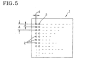
- the punching operation is initiated by the step of punching a plurality of holes including a hole 2 of fine diameter d at intervals A, each of which is at least two times the fine interval ⁇ (two times of a in Fig. 5), by the use of a die punch.
- a plurality of holes are formed first at prescribed intervals A, and then a plurality of holes are formed between the previously punched holes at intervals A so that the distances from the punched holes measure the distance corresponding to the fine interval ⁇ before removing the die punch, cracks that tend to occur when all the holes with fine intervals a are punched at a time can be prevented.
- ceramic green sheets are preferably used as brittle material to be punched according to the invention, compound sheets formed by particles and high polymer, glass epoxy substrates, or organic films dispersed with functional particles are also applicable.
- the fine intervals ⁇ described above may vary depending on the type of brittle material, in case where ceramic green sheets are used, the intervals ⁇ are preferably in the range between 30 and 500 ⁇ m, and more preferably between 30 and 300 ⁇ m.
- the fine diameter d of the holes may vary depending on the type of brittle material as well, in case where ceramic green sheets are used, the fine diameter d is preferably in the range between 20 and 480 ⁇ m, and more preferably in the range between 30 and 200 ⁇ m.
- the fine diameters d for a plurality of holes do not have to be necessarily identical.
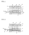
- Fig. 1 is a cross-sectional view showing an example of the punching die according to the invention.
- the die 10 comprises a plurality of punches 11, a punch plate 12, a die 14 including a plurality of fine holes 13, and a stripper 15.
- the plurality of punches 11 respectively comprise a punching tip portion 16, a columnar portion 17 and a base portion 18.
- the columnar portions 17 of the punches are respectively inserted into a plurality of holes formed on the punch plate 12, and a cover portion 20 is placed on the base portions 18 so that the cover portion 20 prevents the base portions 18 that are larger than the columnar portions 17 in diameter from being removed.
- the die 14 comprises a plurality of fine holes 13 of prescribed diameter for insertion and extraction (insertion and removal) of the punching tips 16 of the punches 11, and brittle material to be punched 21 is placed on the die 14.
- the stripper disposed between the punch plate 12 and the die 14 serves to position the punches 11 by gripping the punching tips 16 of the punches 11 and to peel brittle material 21 off the punches 11 so that brittle material to be punched 21 is prevented from being adhered to the punches 11 and from being moved together with the punches 11.
- the reference numeral 22 denotes a stopper disposed on the die 14 on the peripheral side of brittle material 21 to prevent brittle material 21 from being crushed by the stripper 15. Without stopper 22, the stripper 15 may crush brittle material 21, thereby deforming brittle material 21 and thus resulting in the reduced positional accuracy of the holes after being punched.
- a plurality of punches 11 consists of two groups of punches that are different in the position of the apexes of the punching tips 16 from each other.
- two groups of punches one group 11a having the apexes of the punching tips 16 at the higher position and the other group 11b having the apexes of punching tips 16 at the lower position are shown.
- the height of the apexes is differentiated not by changing the length of the columnar portion 17, but by changing the length of the punching tips 16.
- the apex-to-apex distance D between the apexes of punches belonging to the group 11a and the apexes of punches belonging to the group 11b is preferably larger than the thickness t of brittle material, but the relation satisfying (2/3) x t ⁇ D is also acceptable.
- Fig. 2 is a cross sectional view showing another example of the punching die according to the invention, showing three groups of punches; a group of punches 11A of which the apexes of the punching tips 16 are in the highest position, a group of punches 11B of which the apexes of the punching tips 16 are in the middle position, and a group of punches 11C of which the apexes of the punching tips 16 are in the lowest position.
- the apex-to-apex distance D 1 between the apexes of the punches that belong to the group 11A and those belong to the group 11B, and the apex-to-apex distance D 2 between the apexes of the punches that belong to the group 11B and those belong to the group 11C are respectively larger than the thickness t of brittle material, but the relation satisfying (2/3) x t ⁇ D 1 (and D 2 ) is also acceptable.
- the three groups of punches in the embodiment shown in Fig. 2 are arranged in the order of decreasing height of the apex, that is, of group 11A, group 11B, and group 11C consecutively from the left to right, they may be arranged in the order of, for example, group 11A, group 11C, and group 11B from the left to right.
- Fig. 3 is a cross sectional view showing still another example of the punching die according to the invention, in which the height of the apexes are differentiated by changing the length of the columnar portions 17, not by changing the length of the punching tips 16.
- a ceramic green sheet of 0.2 mm in thickness as brittle material was punched by the use of the punching die shown in Fig. 1.
- the interval A is 400 ⁇ m
- the fine interval (pitch) ⁇ is 200 ⁇ m
- the fine diameter d is 150 ⁇ m
- the apex-to-apex distance D that is, the distance between the apexes of the punches belonging to the group 11a and the apexes of the punches belonging to the group 11b is 250 ⁇ m, and where it is 150 ⁇ m, occurrence of cracks could be prevented.
Landscapes
- Engineering & Computer Science (AREA)
- Life Sciences & Earth Sciences (AREA)
- Forests & Forestry (AREA)
- Mechanical Engineering (AREA)
- Manufacturing & Machinery (AREA)
- Microelectronics & Electronic Packaging (AREA)
- Perforating, Stamping-Out Or Severing By Means Other Than Cutting (AREA)
- Punching Or Piercing (AREA)
Abstract
Description
Claims (9)
- A method for forming a plurality of holes of fine diameter d at fine intervals α on brittle material by punching operation, comprising the steps of;punching at least two holes including a hole of fine diameter d at intervals A, each of which is at least two times the fine interval α, by the use of punches of the die; andpunching holes between the previously punched holes at intervals A so that distances from the punched holes of fine diameter d measure at least the distance corresponding to the interval α without removing the die punch.
- A method as set forth in claim 1, wherein said brittle material is a ceramic green sheet.
- A method as set forth in claim 1 or 2, wherein said die punch comprises at least two groups of punches in which the positions of the apexes of the respective tip portions differ from each other, and wherein the shortest apex-to-apex distance D out of the apex-to-apex distances of the respective groups is larger than the thickness of brittle material t.
- A method as set forth in claim 1 or 2, wherein said die punch comprises at least two groups of punches in which the positions of the apexes of the respective tip portions differ from each other, and the relation between the shortest apex-to-apex distance D out of the apex-to-apex distances of the respective group and the thickness of brittle material t satisfies;
- A method as set forth in claims 1 to 4, wherein the fine interval α is in the range between 30 and 500 µm.
- A method as set forth in claims 1 to 5, wherein the fine diameter d is in the range between 20 and 480 µm.
- A punching die comprising;a plurality of punches having punching tips;a punch plate for holding said punches;a die including a plurality of fine holes of prescribed diameter for inserting and removing the punching tips of said punches; anda stripper disposed between said punch plate and said die for holding the tips of said punches and peeling brittle material to be punched off said punch when removing said punches from said die;wherein said plurality of punches is composed of at least two groups of punches and the positions of the apexes of the punching tips of the respective groups differ from each other.
- A punching die as set forth in claim 7, wherein the shortest apex-to-apex distance D out of the apex-to-apex distances between at least two groups is larger than the thickness of brittle material t.
- A punching die as set forth in claim 7, wherein the relation between the apex-to-apex distance D and the thickness brittle material t satisfies the relation;
Applications Claiming Priority (2)
| Application Number | Priority Date | Filing Date | Title |
|---|---|---|---|
| JP24097499A JP2001062784A (en) | 1999-08-27 | 1999-08-27 | Drilling method for brittle material and die for drilling used therefor |
| JP24097499 | 1999-08-27 |
Publications (2)
| Publication Number | Publication Date |
|---|---|
| EP1078721A2 true EP1078721A2 (en) | 2001-02-28 |
| EP1078721A3 EP1078721A3 (en) | 2003-02-05 |
Family
ID=17067438
Family Applications (1)
| Application Number | Title | Priority Date | Filing Date |
|---|---|---|---|
| EP00307241A Withdrawn EP1078721A3 (en) | 1999-08-27 | 2000-08-22 | Method for punching brittle material and punching die to be used therefor |
Country Status (3)
| Country | Link |
|---|---|
| US (1) | US6606926B1 (en) |
| EP (1) | EP1078721A3 (en) |
| JP (1) | JP2001062784A (en) |
Cited By (3)
| Publication number | Priority date | Publication date | Assignee | Title |
|---|---|---|---|---|
| US6637102B2 (en) * | 2000-07-19 | 2003-10-28 | Ngk Insulators, Ltd. | Process for producing an industrial member having throughholes of high aspect ratio |
| EP1878515A1 (en) * | 2006-07-12 | 2008-01-16 | Christoph Burckhardt AG | Perforating device for battery separator |
| CN102275181A (en) * | 2011-06-08 | 2011-12-14 | 潍坊金丝达实业有限公司 | Punching-type garbage crusher |
Families Citing this family (14)
| Publication number | Priority date | Publication date | Assignee | Title |
|---|---|---|---|---|
| JP3930300B2 (en) * | 2001-11-20 | 2007-06-13 | 日本碍子株式会社 | Punching die for simultaneous punching |
| JP4133005B2 (en) * | 2002-06-13 | 2008-08-13 | 株式会社アマダ | Die for punch press |
| JP4517778B2 (en) * | 2004-08-30 | 2010-08-04 | セイコーエプソン株式会社 | Fine hole drilling method and liquid jet head manufacturing apparatus |
| US20060042435A1 (en) * | 2004-08-30 | 2006-03-02 | Seiko Epson Corporation | Working method for forming minute holes, tool used in the method, method and apparatus for manufacturing liquid ejecting head |
| US20070214983A1 (en) * | 2006-03-14 | 2007-09-20 | Yee Chang J | Method and apparatus for punching a printing plate |
| JP2007260820A (en) * | 2006-03-28 | 2007-10-11 | Ngk Insulators Ltd | Manufacturing method of industrial part having through-hole part of high aspect ratio |
| TWI534483B (en) * | 2011-11-01 | 2016-05-21 | 鴻海精密工業股份有限公司 | Shading film stamping device and method for the same |
| TWI458108B (en) * | 2011-12-07 | 2014-10-21 | 財團法人工業技術研究院 | Channel scoring device and channel scribing method |
| JP5794220B2 (en) * | 2012-12-14 | 2015-10-14 | 株式会社村田製作所 | Mold for manufacturing carrier tape and method for manufacturing carrier tape |
| KR101536313B1 (en) * | 2013-12-24 | 2015-07-14 | 디에스글로벌 (주) | Punching apparatus using crank shaft |
| KR101518348B1 (en) * | 2013-12-24 | 2015-05-07 | 디에스글로벌 (주) | Punching apparatus using crank shaft |
| US20170274549A1 (en) * | 2016-03-24 | 2017-09-28 | Lear Corporation | Trim Cover Perforating Apparatus and Method |
| CN109262745A (en) * | 2018-11-21 | 2019-01-25 | 奥士康精密电路(惠州)有限公司 | A kind of pcb board connection position stamping die and its process for stamping |
| GB202011887D0 (en) * | 2020-07-30 | 2020-09-16 | British American Tobacco Investments Ltd | Method and apparatus for manufacturing a consumable unit for an inhalation device |
Family Cites Families (15)
| Publication number | Priority date | Publication date | Assignee | Title |
|---|---|---|---|---|
| US370986A (en) * | 1887-10-04 | Edwin b | ||
| US2825407A (en) * | 1955-03-24 | 1958-03-04 | Plastic Binding Corp | Gang punch |
| US3608413A (en) * | 1969-09-11 | 1971-09-28 | Domenic Borello | Hole punching die arrangement |
| IT8321635U1 (en) * | 1983-04-22 | 1984-10-22 | Terracciano Flora | Punching unit for a punching and/or binding machine for joining sets of sheets with a comb binder |
| DK152266B (en) * | 1985-07-01 | 1988-02-15 | Gyproc Ab | PROCEDURE AND TOOLS FOR HOLIDAYING PLASTICS |
| JPH03142198A (en) | 1989-10-26 | 1991-06-17 | Matsushita Electric Ind Co Ltd | Printed wiring board drilling device |
| US5740712A (en) * | 1992-05-27 | 1998-04-21 | Acco-Rexel Group Services Plc. | Punching devices |
| JP2594732B2 (en) | 1992-07-15 | 1997-03-26 | 協栄プリント技研株式会社 | Die for printed circuit board punching |
| US5303618A (en) * | 1992-09-08 | 1994-04-19 | Norell Ronald A | Via hole punch |
| DE69331782T2 (en) * | 1992-12-07 | 2002-08-08 | Fuji Photo Film Co., Ltd. | perforator |
| GB9311609D0 (en) * | 1993-06-04 | 1993-07-28 | Chemring Ltd | Cutting apparatus |
| US5836226A (en) | 1995-12-25 | 1998-11-17 | Ngk Insulators, Ltd. | Apparatus for progressively feeding and machining sheet material |
| US6047623A (en) * | 1996-03-05 | 2000-04-11 | Performance Design, Inc. | Hole punch quick-change die assembly with pin strap and positioning system |
| US6223636B1 (en) * | 1998-08-03 | 2001-05-01 | International Business Machines Corporation | Low-cost high-density gang punch |
| TW380485U (en) * | 1999-01-21 | 2000-01-21 | Jiang Jou Jen | Combination device of punching and binding for paper |
-
1999
- 1999-08-27 JP JP24097499A patent/JP2001062784A/en active Pending
-
2000
- 2000-08-18 US US09/641,291 patent/US6606926B1/en not_active Expired - Fee Related
- 2000-08-22 EP EP00307241A patent/EP1078721A3/en not_active Withdrawn
Cited By (4)
| Publication number | Priority date | Publication date | Assignee | Title |
|---|---|---|---|---|
| US6637102B2 (en) * | 2000-07-19 | 2003-10-28 | Ngk Insulators, Ltd. | Process for producing an industrial member having throughholes of high aspect ratio |
| EP1878515A1 (en) * | 2006-07-12 | 2008-01-16 | Christoph Burckhardt AG | Perforating device for battery separator |
| WO2008006732A1 (en) * | 2006-07-12 | 2008-01-17 | Christoph Burckhardt Ag | Perforating device for a battery housing wall |
| CN102275181A (en) * | 2011-06-08 | 2011-12-14 | 潍坊金丝达实业有限公司 | Punching-type garbage crusher |
Also Published As
| Publication number | Publication date |
|---|---|
| JP2001062784A (en) | 2001-03-13 |
| EP1078721A3 (en) | 2003-02-05 |
| US6606926B1 (en) | 2003-08-19 |
Similar Documents
| Publication | Publication Date | Title |
|---|---|---|
| US6606926B1 (en) | Method for punching brittle material and punching die to be used therefor | |
| DE69329529T2 (en) | METHOD AND DEVICE FOR SEPARATING IC CHIPS FROM A SEMICONDUCTOR BOARD | |
| US5582086A (en) | Pickup apparatus for picking up a cut sheet from a weak sheet such as a ceramic green sheet | |
| EP1478016A3 (en) | Pattern and fabricating method therefor, device and fabricating method therefor, electro-optical apparatus, electronic apparatus, and method for fabricating active matrix substrate | |
| US6915828B2 (en) | Punch die for punching and laminating simultaneously | |
| EP1265467A3 (en) | Multilayer board having precise perforations and circuit substrate having precise through-holes | |
| EP1842634B1 (en) | Method of manufacturing industrial component having through holes with high aspect ratio | |
| EP3716347A3 (en) | Display device and a manufacturing method thereof | |
| EP1035559A3 (en) | Electron source substrate and image-forming apparatus using the same | |
| JP2002326194A (en) | Dust removal method for punching and method for manufacturing punched product | |
| US6637102B2 (en) | Process for producing an industrial member having throughholes of high aspect ratio | |
| US20230147754A1 (en) | Metalworking apparatus and metalworking method | |
| JP3372315B2 (en) | Perforator | |
| EP1175978B1 (en) | Method for fabrication of industrial parts having high-aspect-ratio through-hole sections | |
| JPH05259587A (en) | Film carrier | |
| US5776283A (en) | Manufacturing method of switch sheet and apparatus thereof | |
| JP2002160195A (en) | Method of manufacturing industrial parts having high aspect ratio through holes | |
| JP2609214B2 (en) | Circuit board dividing method and circuit board dividing mold | |
| EP1871925B1 (en) | Method for electroforming a studded plate | |
| DE102018216198A1 (en) | Semiconductors Cradle | |
| JP3526527B2 (en) | Ceramic substrate | |
| US20070169600A1 (en) | Method and structure to enable fine grid mlc technology | |
| JP2590335Y2 (en) | Ceramic substrate with split grooves | |
| JPH0740325A (en) | Ceramic substrate manufacturing method | |
| JP2002160194A (en) | Method of manufacturing industrial parts having high aspect ratio through-holes |
Legal Events
| Date | Code | Title | Description |
|---|---|---|---|
| PUAI | Public reference made under article 153(3) epc to a published international application that has entered the european phase |
Free format text: ORIGINAL CODE: 0009012 |
|
| AK | Designated contracting states |
Kind code of ref document: A2 Designated state(s): AT BE CH CY DE DK ES FI FR GB GR IE IT LI LU MC NL PT SE |
|
| AX | Request for extension of the european patent |
Free format text: AL;LT;LV;MK;RO;SI |
|
| PUAL | Search report despatched |
Free format text: ORIGINAL CODE: 0009013 |
|
| AK | Designated contracting states |
Designated state(s): AT BE CH CY DE DK ES FI FR GB GR IE IT LI LU MC NL PT SE |
|
| AX | Request for extension of the european patent |
Extension state: AL LT LV MK RO SI |
|
| AKX | Designation fees paid |
Designated state(s): DE FR GB IT NL |
|
| STAA | Information on the status of an ep patent application or granted ep patent |
Free format text: STATUS: THE APPLICATION IS DEEMED TO BE WITHDRAWN |
|
| 18D | Application deemed to be withdrawn |
Effective date: 20030806 |