EP1078669A1 - Process and crystallizer for purifying materials or mixtures thereof - Google Patents
Process and crystallizer for purifying materials or mixtures thereof Download PDFInfo
- Publication number
- EP1078669A1 EP1078669A1 EP99810752A EP99810752A EP1078669A1 EP 1078669 A1 EP1078669 A1 EP 1078669A1 EP 99810752 A EP99810752 A EP 99810752A EP 99810752 A EP99810752 A EP 99810752A EP 1078669 A1 EP1078669 A1 EP 1078669A1
- Authority
- EP
- European Patent Office
- Prior art keywords
- crystallizer
- crystal layer
- gas
- heat exchanger
- temperature
- Prior art date
- Legal status (The legal status is an assumption and is not a legal conclusion. Google has not performed a legal analysis and makes no representation as to the accuracy of the status listed.)
- Withdrawn
Links
Images


Classifications
-
- C—CHEMISTRY; METALLURGY
- C07—ORGANIC CHEMISTRY
- C07D—HETEROCYCLIC COMPOUNDS
- C07D201/00—Preparation, separation, purification or stabilisation of unsubstituted lactams
- C07D201/16—Separation or purification
-
- B—PERFORMING OPERATIONS; TRANSPORTING
- B01—PHYSICAL OR CHEMICAL PROCESSES OR APPARATUS IN GENERAL
- B01D—SEPARATION
- B01D9/00—Crystallisation
- B01D9/0004—Crystallisation cooling by heat exchange
- B01D9/0013—Crystallisation cooling by heat exchange by indirect heat exchange
-
- B—PERFORMING OPERATIONS; TRANSPORTING
- B01—PHYSICAL OR CHEMICAL PROCESSES OR APPARATUS IN GENERAL
- B01D—SEPARATION
- B01D9/00—Crystallisation
- B01D9/004—Fractional crystallisation; Fractionating or rectifying columns
-
- B—PERFORMING OPERATIONS; TRANSPORTING
- B01—PHYSICAL OR CHEMICAL PROCESSES OR APPARATUS IN GENERAL
- B01D—SEPARATION
- B01D9/00—Crystallisation
- B01D9/0059—General arrangements of crystallisation plant, e.g. flow sheets
-
- B—PERFORMING OPERATIONS; TRANSPORTING
- B01—PHYSICAL OR CHEMICAL PROCESSES OR APPARATUS IN GENERAL
- B01D—SEPARATION
- B01D9/00—Crystallisation
- B01D9/0072—Crystallisation in microfluidic devices
-
- C—CHEMISTRY; METALLURGY
- C07—ORGANIC CHEMISTRY
- C07C—ACYCLIC OR CARBOCYCLIC COMPOUNDS
- C07C17/00—Preparation of halogenated hydrocarbons
- C07C17/38—Separation; Purification; Stabilisation; Use of additives
- C07C17/392—Separation; Purification; Stabilisation; Use of additives by crystallisation; Purification or separation of the crystals
-
- C—CHEMISTRY; METALLURGY
- C07—ORGANIC CHEMISTRY
- C07C—ACYCLIC OR CARBOCYCLIC COMPOUNDS
- C07C201/00—Preparation of esters of nitric or nitrous acid or of compounds containing nitro or nitroso groups bound to a carbon skeleton
- C07C201/06—Preparation of nitro compounds
- C07C201/16—Separation; Purification; Stabilisation; Use of additives
-
- C—CHEMISTRY; METALLURGY
- C07—ORGANIC CHEMISTRY
- C07C—ACYCLIC OR CARBOCYCLIC COMPOUNDS
- C07C209/00—Preparation of compounds containing amino groups bound to a carbon skeleton
- C07C209/82—Purification; Separation; Stabilisation; Use of additives
- C07C209/84—Purification
-
- C—CHEMISTRY; METALLURGY
- C07—ORGANIC CHEMISTRY
- C07C—ACYCLIC OR CARBOCYCLIC COMPOUNDS
- C07C253/00—Preparation of carboxylic acid nitriles
- C07C253/32—Separation; Purification; Stabilisation; Use of additives
- C07C253/34—Separation; Purification
-
- C—CHEMISTRY; METALLURGY
- C07—ORGANIC CHEMISTRY
- C07C—ACYCLIC OR CARBOCYCLIC COMPOUNDS
- C07C263/00—Preparation of derivatives of isocyanic acid
- C07C263/18—Separation; Purification; Stabilisation; Use of additives
- C07C263/20—Separation; Purification
-
- C—CHEMISTRY; METALLURGY
- C07—ORGANIC CHEMISTRY
- C07C—ACYCLIC OR CARBOCYCLIC COMPOUNDS
- C07C37/00—Preparation of compounds having hydroxy or O-metal groups bound to a carbon atom of a six-membered aromatic ring
- C07C37/68—Purification; separation; Use of additives, e.g. for stabilisation
- C07C37/70—Purification; separation; Use of additives, e.g. for stabilisation by physical treatment
- C07C37/84—Purification; separation; Use of additives, e.g. for stabilisation by physical treatment by crystallisation
-
- C—CHEMISTRY; METALLURGY
- C07—ORGANIC CHEMISTRY
- C07C—ACYCLIC OR CARBOCYCLIC COMPOUNDS
- C07C51/00—Preparation of carboxylic acids or their salts, halides or anhydrides
- C07C51/42—Separation; Purification; Stabilisation; Use of additives
- C07C51/43—Separation; Purification; Stabilisation; Use of additives by change of the physical state, e.g. crystallisation
-
- C—CHEMISTRY; METALLURGY
- C07—ORGANIC CHEMISTRY
- C07C—ACYCLIC OR CARBOCYCLIC COMPOUNDS
- C07C7/00—Purification; Separation; Use of additives
- C07C7/14—Purification; Separation; Use of additives by crystallisation; Purification or separation of the crystals
-
- C—CHEMISTRY; METALLURGY
- C11—ANIMAL OR VEGETABLE OILS, FATS, FATTY SUBSTANCES OR WAXES; FATTY ACIDS THEREFROM; DETERGENTS; CANDLES
- C11B—PRODUCING, e.g. BY PRESSING RAW MATERIALS OR BY EXTRACTION FROM WASTE MATERIALS, REFINING OR PRESERVING FATS, FATTY SUBSTANCES, e.g. LANOLIN, FATTY OILS OR WAXES; ESSENTIAL OILS; PERFUMES
- C11B15/00—Solidifying fatty oils, fats, or waxes by physical processes
-
- C—CHEMISTRY; METALLURGY
- C11—ANIMAL OR VEGETABLE OILS, FATS, FATTY SUBSTANCES OR WAXES; FATTY ACIDS THEREFROM; DETERGENTS; CANDLES
- C11B—PRODUCING, e.g. BY PRESSING RAW MATERIALS OR BY EXTRACTION FROM WASTE MATERIALS, REFINING OR PRESERVING FATS, FATTY SUBSTANCES, e.g. LANOLIN, FATTY OILS OR WAXES; ESSENTIAL OILS; PERFUMES
- C11B7/00—Separation of mixtures of fats or fatty oils into their constituents, e.g. saturated oils from unsaturated oils
- C11B7/0075—Separation of mixtures of fats or fatty oils into their constituents, e.g. saturated oils from unsaturated oils by differences of melting or solidifying points
-
- C—CHEMISTRY; METALLURGY
- C07—ORGANIC CHEMISTRY
- C07C—ACYCLIC OR CARBOCYCLIC COMPOUNDS
- C07C2603/00—Systems containing at least three condensed rings
- C07C2603/02—Ortho- or ortho- and peri-condensed systems
- C07C2603/04—Ortho- or ortho- and peri-condensed systems containing three rings
- C07C2603/06—Ortho- or ortho- and peri-condensed systems containing three rings containing at least one ring with less than six ring members
- C07C2603/10—Ortho- or ortho- and peri-condensed systems containing three rings containing at least one ring with less than six ring members containing five-membered rings
- C07C2603/12—Ortho- or ortho- and peri-condensed systems containing three rings containing at least one ring with less than six ring members containing five-membered rings only one five-membered ring
- C07C2603/18—Fluorenes; Hydrogenated fluorenes
-
- C—CHEMISTRY; METALLURGY
- C07—ORGANIC CHEMISTRY
- C07C—ACYCLIC OR CARBOCYCLIC COMPOUNDS
- C07C2603/00—Systems containing at least three condensed rings
- C07C2603/02—Ortho- or ortho- and peri-condensed systems
- C07C2603/04—Ortho- or ortho- and peri-condensed systems containing three rings
- C07C2603/06—Ortho- or ortho- and peri-condensed systems containing three rings containing at least one ring with less than six ring members
- C07C2603/10—Ortho- or ortho- and peri-condensed systems containing three rings containing at least one ring with less than six ring members containing five-membered rings
- C07C2603/12—Ortho- or ortho- and peri-condensed systems containing three rings containing at least one ring with less than six ring members containing five-membered rings only one five-membered ring
- C07C2603/20—Acenaphthenes; Hydrogenated acenaphthenes
-
- C—CHEMISTRY; METALLURGY
- C07—ORGANIC CHEMISTRY
- C07C—ACYCLIC OR CARBOCYCLIC COMPOUNDS
- C07C2603/00—Systems containing at least three condensed rings
- C07C2603/02—Ortho- or ortho- and peri-condensed systems
- C07C2603/04—Ortho- or ortho- and peri-condensed systems containing three rings
- C07C2603/22—Ortho- or ortho- and peri-condensed systems containing three rings containing only six-membered rings
- C07C2603/26—Phenanthrenes; Hydrogenated phenanthrenes
Definitions
- the invention relates to a method according to the preamble of claim 1 and a crystallizer according to the preamble of claim 11 for separation or Cleaning of dissolved, molten or liquid compounds or Connection mixtures.
- the crystal layer is then sweated and melted, by the heat transfer medium flowing past on the outside of the tubes is heated continuously or in discrete steps.
- the crystal layer is heated exclusively by the Heat exchanger surfaces through.
- the crystal layer is heated such that different fractions can be obtained, namely one so - called “sweating phase", which occurs when the crystals sweat, and a “crystal phase", which the crystal layer after sweating corresponds.
- the fractions resulting from the cleaning process i.e. the non-crystallized Residue or mother liquor, the sweat and crystal phase, can then be subjected to one or more further cleaning cycles be until the compound is in the desired purity resp. the Impurities in the mother liquor are highly enriched.
- the crystallization process described above can also be carried out using a perform static crystallizer.
- the static crystallizer consists of a container in which a number of mostly flat Heat exchanger surfaces are arranged. These heat exchanger surfaces can consist of double-walled cooling elements, which by a Heat transfer medium are flowed through.
- the so-called static The crystallization process differs from that described at the beginning dynamic process in that the tank filling at Crystallization process remains "static", i.e. not circulated or stirred becomes. Accordingly, the static crystallization process is important slower than that with a falling film crystallizer or a crystallizer dynamic crystallization processes applied with full tube filling.
- the object of the present invention is to implement the known methods for Cleaning connections or Connection mixtures by means of to improve fractional crystallization. Another goal is a better one To achieve separation performance in the fractional crystallization. It is also a The aim is to make the process more economical. Another job of The present invention is an apparatus for performing the To provide the procedure.
- Another advantage of the method is that by adding heat from two sides (liquid heat transfer medium on that of the crystal layer opposite side of the heat exchanger surfaces and gaseous Heat transfer medium on the side of the crystal layer Heat exchanger surfaces) the speed for the melting of the formed crystal layer can be increased.
- Gas sweating is particularly advantageous for substances or mixtures of substances, which are known to adhere poorly to the heat exchanger surfaces.
- the substances or mixtures of substances to be cleaned be sweated exclusively by gas sweating, which in the Heat exchanger surfaces circulating or. at that of the crystal layer downward-facing side of the heat exchanger surfaces Heat transfer medium preferably at a temperature below the Melting temperature of the substance to be cleaned resp. Mixed materials kept so that the layer adheres well to the heat exchanger surfaces is guaranteed.
- the melting advantageously takes place by placing the crystal layer first sweating (so-called sweating phase) and then melting (so-called Melting phase), at least temporarily for sweating Gas flow of a gaseous heat transfer medium over the crystal layer is directed.
- the sweating of the crystal layer can only be caused by the Use of the heated gas flow.
- By feeding Heat also from the side of the crystal layer facing away from the Heat exchanger surfaces forth (by means of a liquid or, if necessary gaseous heat transfer medium) can shorten the sweating phase become.
- the temperature of the sweat is advantageous on the one hand Heat transfer medium increased and on the other hand at least temporarily heated gas stream of a gaseous heat transfer medium over the Headed crystal layer.
- the heated gas stream essentially during the entire melting process, i.e. during the Crystal sweating and melting of the crystals used.
- the cleaning process can be shortened significantly and the Economics of the process can be improved.
- the gas can be a Noble gas, nitrogen, air, carbon dioxide, water vapor, freon, aliphatic or cyclic unsubstituted hydrocarbons, substituted halogenated hydrocarbons such as. Be a freone.
- the gas flow in the opposite direction to the flowing melt over the Can be passed is according to a preferred embodiment variant in the direction of the flowing Melt passed over the crystal layer. That means the heated gas flow is introduced in the top area of the crystallizer and in the lower area of the Crystallizer removed again. This results in a comparative better separation performance than if the gas flow in the opposite direction flowing melt is passed over the crystal layer.
- the gas stream is advantageously circulated.
- the Gas stream heated to a temperature which is at least 5 ° C, preferably at least 15 ° C and most preferably at least 25 ° C above Melting point of the crystals forming the crystal layer is. Because gases or Gas mixtures have a comparatively low heat content The melting process is easy to control. Gases can provide enough energy are supplied so that on the one hand a noticeable improvement in Separation performance and on the other hand a significant acceleration of the Procedure is achieved.
- the gas flow is heated can, by supplying a certain amount of energy per unit of time, according to a preferred variant, the gas flow is heated in a controlled manner. This has the advantage that the cleaning process can be easily optimized.
- Gas sweating is particularly advantageous for cleaning wax-like compounds or compound mixtures, Fatty acid mixtures, acrylic acid used by fractional crystallization.
- the crystal layer is sweated before melting by at least temporarily a gas stream of a gaseous one Heat transfer medium is passed over the crystal layer, the Gas flow is previously heated to a temperature which is higher than that Melting temperature of the crystal layer is.
- the present invention also relates to a crystallizer Characteristic of claim 11 characterized by at least one Gas inlet for the inlet of a gas into the container space and at least a gas outlet for the outlet of the gaseous container content from the Container space, a gas supply line with heating means, which with the gas inlet is connected to the heating of the gas to be supplied, and Funding to promote the gas in the container space, respectively. out of this out.
- the crystallizer according to the invention has the advantage that it allows heated gas to enter the crystallizer room and dissipate and thus increase the separation performance and throughput.
- the gas inlet and the Gas outlet connected to each other by a connecting line. This allows the gas to be circulated and used several times.
- the Connection line can partially through the circulation line to Circulation of the melt can be formed, since when the Crystal layer usually no circulation of the accumulated on the ground liquid tank content more takes place.
- the one gas connection point is expediently at a distance from the Crystallizer bottom provided. This prevents liquid (Melt) unintentionally leak or into the connecting line for the Circulation of the gas can occur.
- the gas connection line can be shut off by means of shut-off means so that they are also connected closer to the ground can.
- the heating means through an electrically heated heating surface or Heating coil can be formed, these are advantageous as a heat exchanger, e.g. a heating coil in which a heat exchange medium circulate can, trained.
- a heat exchanger has the advantage that Temperature is well adjustable.
- the heating means are expediently available a temperature sensor and a regulating valve which controls the flow of the heat exchange medium in the heat exchanger, in connection.
- a control circuit is implemented in connection with a control unit and the cleaning process can thus be optimized and, if this once optimized, easily controllable and reproducible.
- They are advantageous Funding designed in such a way that in operation the gas from the bottom to Head area of the crystallizer is promoted.
- the process according to the invention and the crystallizer according to the invention are particularly suitable for the purification of the following compounds: acrylic acid, methacrylic acid, waste water, methyl diphenyl isocyanate (MDI), toluene diisocyanate (TDI), caprolactam, benzoic acid, bisphenol A, nitrochlorobenzene, straight-chain and branched fatty acids, hydrazine, phenols such as para, meta and ortho-cresol, 2,6 and 3,5-dimethylphenol, naphthol and o, o-diphenol, chlorinated hydrocarbons such as dichlorobenzene and nitrochlorobenzene, naphthalene, 1- 2-methylnaphthalene, acenaphthene, fluorene, phenanthrene, adiponitrile, hexamethylene diamine , Lactides (polylactides), chlorpyrifos and paraffins from C 17 .
- the method can also be
- the crystallizer 11 according to FIG. 1 has a container 13 with a Container space 14, in which a number of cooling or. heatable Crystallization or heat exchanger surfaces 15 are arranged.
- the Heat exchanger surfaces 15 extend coaxially to the longitudinal axis of the container from the top area 17 of the crystallizer to the bottom area 19.
- Purpose The lines, pumps and Heat exchanger apparatus, which in connection with the Heat exchanger surfaces a cooling or. Form heat cycle, not drawn.
- the bottom area 19 corresponds approximately to the filling volume of the crystallizer 11.
- a circulation line 21 connects one Junction 20 in the bottom region 19 of the crystallizer with a second one Junction 22 in the head region 17.
- a pump 23 is used for delivery of the liquid tank content in operation in the bottom area 19 to the crystallizer head area 17 so that the liquid to be cleaned or Mother liquor as a falling or trickle film on the heat exchanger surfaces can flow down.
- a valve 25 Liquid circulation line 21 can be shut off.
- a line 27 with Shut-off valve 29 is used for closing and Removal of raw and cleaned Material.
- the crystallizer differs from known ones Crystallizers in that means are provided to a heated gas to lead along the heat exchanger surfaces 15. This has the advantage that throughput can be increased and separation performance improved because the sweating and melting process accelerates and, surprisingly, the cleaning effect can be improved.
- the crystallizer 11 according to FIG. 1 has a for the circulation of a gas line connection, which the the below the Heat exchanger surfaces lying crystallizer room with that above that connects the heat exchanger surfaces so that the gaseous tank content circulates and a gas stream is directed past the heat exchanger surfaces can be.
- the line connection is realized according to Figure 1 by a Connection line 31, which is at a distance from the crystallizer bottom 33 Connects container space with the circulation line 21.
- the circulation line 21, which opens into the crystallizer cover 35, can be used to promote the Gases are used because during the sweat and part of the Melting phase, no melt is circulated in the circulation line 21 and it is therefore empty.
- the improvement according to the invention can be done with little effort with existing crystallizers to increase performance be retrofitted.
- the connecting line 31 can be shut off by valves 37, 39.
- a blower 41 serves to promote the gas located in line 31, e.g. Air.
- the Gas is through a heat exchanger arranged in the connecting line 31 43 warmed.
- the heat exchanger 43 can have a heat exchanger surface, an electric heating coil, an oven which surrounds the line 31 is arranged around, or the like.
- To get the gas on as quickly as possible is the heat exchanger 43 preferably integrated into the connecting line 31.
- a temperature sensor 51 and a control unit 53 form together a control loop, which the compliance of defined and enable reproducible conditions over a longer period of time.
- the crystallizer 11a according to FIG. 2 differs from that of Figure 1 in that the connecting line 31a is not in the Liquid circulation line but directly into the crystallizer cover flows.
- the connecting line 31a is through a with the reference number 55 designated shut-off valve lockable.
- the Heat exchanger surfaces essentially over the entire height of the Crystallizer. Accordingly, the gas outlet is closer to the gas circulation to choose the floor than with a falling film crystallizer. Basically It is also conceivable that the devices, lines, etc. at least partially in the Lead crystallizer.
- the cleaning of a compound mixture by means of layer crystallization e.g. in a falling film crystallizer, this is done as follows: liquid compound mixture is introduced into the crystallizer, the amount introduced can reach just up to the heat exchanger surfaces. Thereafter, the liquid compound mixture is circulated in line 21, and lowered the temperature of the heat exchanger surfaces 15 by the in this circulating heat exchange medium by means of a heat exchanger is cooled. As soon as the heat exchanger surfaces 15 a certain Temperature below the melting temperature of the desired compound reached, this begins to crystallize and on the heat exchanger surfaces to be deposited as a crystal layer. If the crystal layer is a certain one Has reached strength, the crystallization process is stopped and the drained non-crystallized mother liquor into a tank.
- cleaning can also be carried out substances or mixtures of substances that adhere poorly to the heat exchanger surfaces the heat exchange medium circulating in the heat exchangers on one Leave the temperature below the crystallization temperature of the layer and sweating exclusively through a heated gas flow respectively. This has the advantage of being good during sweating Adhesion of the crystal layer to the crystallizer surfaces is ensured.
- the crystallization process in a static crystallizer differs differ from that described above in that the crystallizer is so far with Melt is filled that the heat exchanger surfaces through the melt are covered. Then the heat exchanger surfaces are cooled and that desired product deposited as a crystal layer, during which Crystallization process practically no agitation of the liquid Crystallizer content takes place.
- the sweating and melting of the Crystal layer can as above with the help of a heated gas flow take place, also in the static crystallization process Improvement in separation performance is achievable.
- FIG. 3 shows the improvement based on a comparative illustration can be achieved with the method according to the invention.
- the anhydrous butterfat used had one before cleaning Clear point of 36 ° C. Due to the dynamic crystallization used Fall film increased the clarity of the butter fat to about 43 to 44 ° C (curve a).
- Samples 1 to 4 were then sweated conventionally.
- To the (conventional) sweating i.e. Warming the secluded Crystal layer through the circulating in the heat exchanger surfaces Heat transfer medium, the heat transfer medium was during 20 Leave at a temperature of 35 ° C for minutes. Prolonged sweating was due to the low adhesion of the crystal layer to the Prevents heat exchanger surfaces (risk of slipping of the layer). After sweating, the crystal layer became clear again measured (curve b).
- curve a (experiments 1 to 4) with curve b shows that through the well-known sweating process from the inside (i.e. via the Heat exchanger surfaces) the clear point can be increased by approx. 1.0 to 1.2 ° C could.
- the new process is advantageously suitable for the purification of acrylic acid, methacrylic acid, waste water, methyl diphenyl isocyanate (MDI), toluenediisocyanate (TDI), caprolactam, benzoic acid, bisphenol A, nitrochlorobenzene, straight-chain and branched fatty acid, hydrazine, phenols such as para, meta and ortho-cresol, 2,6 and 3,5-dimethylphenol, naphthol and o, o-diphenol, chlorinated hydrocarbons such as dichlorobenzene and nitrochlorobenzene, naphthalene, 1- 2-methylnaphthalene, acenaphthene, fluorene, phenanthrene, adiponitrile, hexamethylenediamine, lactide (polylactide) Chlorpyrifos, fatty acid mixtures, butterfat and paraffins from C 17 .
- MDI methyl diphenyl isocyan
- the method according to the invention can be used with all crystallizer types (e.g. falling film type, fully flowed tube, crystallizer with flat, e.g. double-walled, heat exchanger surfaces), which are dynamic or use a static crystallization process and the one to be cleaned Compound is deposited as a crystal layer on heat exchanger surfaces.
- crystallizer types e.g. falling film type, fully flowed tube, crystallizer with flat, e.g. double-walled, heat exchanger surfaces
- Existing crystallizers can be retrofitted with little effort be to the application of gas sweating according to the invention enable.
Abstract
Description
Die Erfindung betrifft ein Verfahren gemäss Oberbegriff von Anspruch 1 und
einen Kristallisator gemäss Oberbegriff von Anspruch 11 zur Trennung oder
Reinigung von gelösten, geschmolzenen oder flüssigen Verbindungen oder
Verbindungsgemischen.The invention relates to a method according to the preamble of
Die US 3,621,664 (Saxer), deren Offenbarungsgehalt hiermit unter Bezugnahme aufgenommen wird, offenbart einen Kristallisator bestehend aus einem in einem Behälter angeordneten Rohrbündel. Der Kristallisator wird zur Reinigung von verunreinigten Verbindungen resp. der Trennung von Stoffgemischen eingesetzt. Bei der Reinigung wird eine Schmelze des zu reinigenden Gemisches als Fallfilm oder als volle Rohrfüllung durch die Rohre geleitet. Zur Abscheidung der gewünschten Verbindung als auf der Innenseite der Rohre anhaftende Kristallschicht werden die Rohre von aussen mittels eines Wärmetransfermediums gekühlt, welches ebenfalls als Rieselfilm an der Aussenseite der Rohre herunterfliessen kann. Die beim Abkühlen gebildete Kristallschicht enthält die gewünschte Verbindung in höherer Reinheit als die Schmelze. Die Kristallschicht wird sodann geschwitzt und abgeschmolzen, indem das auf der Aussenseite der Rohre vorbeiströmende Wärmetransfermedium kontinuierlich oder in diskreten Schritten erwärmt wird. Die Erwärmung der Kristallschicht erfolgt dabei ausschliesslich durch die Wärmetauscherflächen hindurch. Die Erwärmung der Kristallschicht erfolgt derart, dass verschiedene Fraktionen gewonnen werden können, nämlich eine sogenannte "Schwitzphase", welche beim Schwitzen der Kristalle anfällt, und einer "Kristallphase", welche der Kristallschicht nach dem Schwitzen entspricht.US 3,621,664 (Saxer), the disclosure content of which is hereby incorporated by reference Reference is made, discloses a crystallizer consisting of a tube bundle arranged in a container. The crystallizer becomes Cleaning contaminated connections resp. the separation of Mixtures of substances used. When cleaning, a melt of the cleaning mixture as falling film or as a full pipe filling through the pipes headed. To separate the desired connection as on the inside of the crystal layer adhering to the tubes are from the outside by means of a heat transfer medium cooled, which is also a trickle film on the Can flow down the outside of the pipes. The one formed on cooling Crystal layer contains the desired compound in higher purity than that Melt. The crystal layer is then sweated and melted, by the heat transfer medium flowing past on the outside of the tubes is heated continuously or in discrete steps. The The crystal layer is heated exclusively by the Heat exchanger surfaces through. The crystal layer is heated such that different fractions can be obtained, namely one so - called "sweating phase", which occurs when the crystals sweat, and a "crystal phase", which the crystal layer after sweating corresponds.
Die beim Reinigungsverfahren anfallenden Fraktionen, d.h. der nicht-kristallisierte Rückstand oder Mutterlauge, die Schwitz- und die Kristallphase, können sodann einem oder mehreren weiteren Reinigungszyklen unterworfen werden, bis die Verbindung in der gewünschten Reinheit vorliegt resp. die Verunreinigungen in der Mutterlauge stark angereichert sind.The fractions resulting from the cleaning process, i.e. the non-crystallized Residue or mother liquor, the sweat and crystal phase, can then be subjected to one or more further cleaning cycles be until the compound is in the desired purity resp. the Impurities in the mother liquor are highly enriched.
Ein Einsatzgebiet des oben beschriebenen Reinigungsverfahrens ist die grosstechnische Reinigung von Ausgangsstoffen, wie substituierte und unsubstituierte Naphthaline, Acrylsäure etc. Aufgrund der riesigen, jährlich zu reinigenden Mengen ist die Wirtschaftlichkeit der eingesetzten Verfahren von grösster Bedeutung. Dabei spielt der Durchsatz und die eingesetzte Energie eine entscheidende Rolle.One area of application of the cleaning process described above is industrial cleaning of raw materials, such as substituted and unsubstituted naphthalenes, acrylic acid etc. due to the huge, annual increase cleaning amounts is the economy of the processes used by of greatest importance. The throughput and the energy used play here a crucial role.
Das oben beschriebene Kristallisationsverfahren lässt sich auch mittels eines statischen Kristallisators durchführen. Der statische Kristallisator besteht aus einem Behälter, in welchem eine Anzahl von meist flachen Wärmetauscherflächen angeordnet sind. Diese Wärmetauscherflächen können aus doppelwandigen Kühlelementen bestehen, welche von einem Wärmetransfermedium durchströmt werden. Das sog. statische Kristallisationsverfahren unterscheidet sich vom eingangs beschriebenen dynamischen Verfahren darin, dass die Tankfüllung beim Kristallisationsvorgang "statisch" verharrt, d.h. nicht zirkuliert oder gerührt wird. Entsprechend ist das statische Kristallisationsverfahren bedeutend langsamer als das bei einem Fallfilmkristallisator oder einem Kristallisator mit voller Rohrfüllung angewandte dynamische Kristallisationsverfahren.The crystallization process described above can also be carried out using a perform static crystallizer. The static crystallizer consists of a container in which a number of mostly flat Heat exchanger surfaces are arranged. These heat exchanger surfaces can consist of double-walled cooling elements, which by a Heat transfer medium are flowed through. The so-called static The crystallization process differs from that described at the beginning dynamic process in that the tank filling at Crystallization process remains "static", i.e. not circulated or stirred becomes. Accordingly, the static crystallization process is important slower than that with a falling film crystallizer or a crystallizer dynamic crystallization processes applied with full tube filling.
Aufgabe der vorliegenden Erfindung ist es, die bekannten Verfahren zur Reinigung von Verbindungen resp. Verbindungsgemischen mittels fraktionierter Kristallisation zu verbessern. Ein weiteres Ziel ist eine bessere Trennleistung bei der fraktionierten Kristallisation zu erzielen. Zudem ist es ein Ziel, das Verfahren wirtschaftlicher zu gestalten. Eine weitere Aufgabe der vorliegenden Erfindung ist es, eine Vorrichtung zur Durchführung des Verfahrens zur Verfügung zu stellen.The object of the present invention is to implement the known methods for Cleaning connections or Connection mixtures by means of to improve fractional crystallization. Another goal is a better one To achieve separation performance in the fractional crystallization. It is also a The aim is to make the process more economical. Another job of The present invention is an apparatus for performing the To provide the procedure.
Erfindungsgemäss wird dies durch ein Verfahren realisiert, bei welchem
Dieses Verfahren, nachfolgend auch als Gasschwitzen bezeichnet, hat den überraschenden Vorteil, dass durch den Gasstrom die Trennleistung verbessert wird. Obwohl die genauen Ursachen nicht völlig geklärt sind, wird angenommen, dass durch das gasförmige Wärmetransfermedium der Stoffaustausch zwischen der Kristall- und der Flüssigphase verstärkt wird, was eine bessere Trennung im Vergleich zu Verfahren, bei welchen kein gasförmiges Wärmetransfermedium über die Kristallschicht geleitet wird, zur Folge hat. Da die Verunreinigungen vornehmlich an der Oberfläche der Kristalle angereichert sind, lassen sich die Verunreinigungen beim Schwitzen mit einem gasförmigen Medium bevorzugt abschmelzen. Beim Gasschwitzen können die Poren geöffnet werden, wobei die Viskosität der anhaftenden Schmelze herabgesetzt wird, die Kristallschicht im übrigen aber stabil bleibt. Die von oben nach unten fliessende Schwitzflüssigkeit wirkt als Waschflüssigkeit für die von der Schwitzflüssigkeit überstrichene Kristallschicht.This process, hereinafter also referred to as gas sweating, has the surprising advantage that the separation performance by the gas flow is improved. Although the exact causes are not fully understood, assumed that the gaseous heat transfer medium Mass transfer between the crystal and the liquid phase is reinforced what a better separation compared to processes in which no gaseous heat transfer medium is passed over the crystal layer for Consequence. Since the contaminants are mainly on the surface of the Crystals are enriched, the impurities when sweating preferably melt with a gaseous medium. When sweating gas the pores can be opened, the viscosity of the adhering Melt is reduced, but the crystal layer remains stable. The sweat flowing from top to bottom acts as Washing liquid for the swab swept by the sweating liquid Crystal layer.
Ein weiterer Vorteil des Verfahrens ist, dass durch eine Wärmezufuhr von zwei Seiten (flüssiges Wärmetransfermedium auf der der Kristallschicht abgewandten Seite der Wärmetauscherflächen und gasförmiges Wärmetransfermedium auf der die Kristallschicht aufweisenden Seite der Wärmetauscherflächen) die Geschwindigkeit für das Abschmelzen der gebildeten Kristallschicht erhöht werden kann.Another advantage of the method is that by adding heat from two sides (liquid heat transfer medium on that of the crystal layer opposite side of the heat exchanger surfaces and gaseous Heat transfer medium on the side of the crystal layer Heat exchanger surfaces) the speed for the melting of the formed crystal layer can be increased.
Besonders vorteilhaft ist das Gasschwitzen bei Stoffen oder Stoffgemischen, welche bekanntermassen an den Wärmetauscherflächen schlecht haften. In solchen Fällen können die zu reinigenden Stoffe oder Stoffgemische ausschliesslich durch Gasschwitzen geschwitzt werden, wobei das in den Wärmetauscherflächen zirkulierende resp. an der der Kristallschicht abgewandten Seite der Wärmetauscherflächen herabfliessende Wärmetransfermedium vorzugsweise auf einer Temperatur unterhalb der Schmelztemperatur des zu reinigenden Stoffes resp. Stoffgemisches gehalten wird, sodass eine gute Haftung der Schicht an den Wärmetauscherflächen gewährleistet ist.Gas sweating is particularly advantageous for substances or mixtures of substances, which are known to adhere poorly to the heat exchanger surfaces. In In such cases, the substances or mixtures of substances to be cleaned be sweated exclusively by gas sweating, which in the Heat exchanger surfaces circulating or. at that of the crystal layer downward-facing side of the heat exchanger surfaces Heat transfer medium preferably at a temperature below the Melting temperature of the substance to be cleaned resp. Mixed materials kept so that the layer adheres well to the heat exchanger surfaces is guaranteed.
Vorteilhaft geschieht das Schmelzen, indem die Kristallschicht zuerst geschwitzt (sog. Schwitzphase) und dann abgeschmolzen wird (sog. Schmelzphase), wobei wenigstens zum Schwitzen wenigstens zeitweise ein Gasstrom eines gasförmigen Wärmetransfermediums über die Kristallschicht geleitet wird. Das Schwitzen der Kristallschicht kann ausschliesslich durch den Einsatz des erwärmten Gasstromes erfolgen. Durch die Zuführung von Wärme auch von der der Kristallschicht abgewandten Seite der Wärmetauscherflächen her (mittels eines flüssigen oder gegebenenfalls gasförmigen Wärmetransfermediums) kann die Schwitzphase verkürzt werden. Vorteilhaft wird zum Schwitzen einerseits die Temperatur des Wärmetransfermediums erhöht und andererseits wenigstens zeitweise ein erwärmter Gasstrom eines gasförmigen Wärmetransfermediums über die Kristallschicht geleitet.The melting advantageously takes place by placing the crystal layer first sweating (so-called sweating phase) and then melting (so-called Melting phase), at least temporarily for sweating Gas flow of a gaseous heat transfer medium over the crystal layer is directed. The sweating of the crystal layer can only be caused by the Use of the heated gas flow. By feeding Heat also from the side of the crystal layer facing away from the Heat exchanger surfaces forth (by means of a liquid or, if necessary gaseous heat transfer medium) can shorten the sweating phase become. The temperature of the sweat is advantageous on the one hand Heat transfer medium increased and on the other hand at least temporarily heated gas stream of a gaseous heat transfer medium over the Headed crystal layer.
Gemäss einer bevorzugten Ausführungsvariante wird der erwärmte Gasstrom im wesentlichen während des ganzen Schmelzvorgangs, also während des Kristallschwitzens und des Abschmelzens der Kristalle, eingesetzt. Damit kann der Reinigungsprozess bedeutend verkürzt werden und die Wirtschaftlichkeit des Verfahrens verbessert werden.According to a preferred embodiment, the heated gas stream essentially during the entire melting process, i.e. during the Crystal sweating and melting of the crystals used. In order to the cleaning process can be shortened significantly and the Economics of the process can be improved.
Obwohl grundsätzlich die unterschiedlichsten Gase eingesetzt werden können, wird vorzugsweise ein inertes oder bezüglich des zu reinigenden Verbindungsgemisches nicht-reaktives Gas eingesetzt. Das Gas kann ein Edelgas, Stickstoff, Luft, Kohlendioxid, Wasserdampf, Freon, aliphatische oder cyclische unsubstituierte Kohlenwasserstoffe, substituierte Halogen-Kohlenwasserstoffe wie z.B. Freone sein.Although the most varied of gases are used in principle can, is preferably an inert or with respect to the to be cleaned Connection mixture non-reactive gas used. The gas can be a Noble gas, nitrogen, air, carbon dioxide, water vapor, freon, aliphatic or cyclic unsubstituted hydrocarbons, substituted halogenated hydrocarbons such as. Be a freone.
Obwohl der Gasstrom in Gegenrichtung zur abfliessenden Schmelze über die Kristallschicht geleitet werden kann, wird der Gasstrom gemäss einer bevorzugten Ausführungsvariante in Gleichrichtung zur abfliessenden Schmelze über die Kristallschicht geleitet. Das heisst, der erwärmte Gasstrom wird im Kopfbereich des Kristallisators eingeleitet und im unteren Bereich des Kristallisators wieder abgeführt. Dadurch ergibt sich eine vergleichsweise bessere Trennleistung, als wenn der Gasstrom in Gegenrichtung zur abfliessenden Schmelze über die Kristallschicht geleitet wird.Although the gas flow in the opposite direction to the flowing melt over the Can be passed, the gas flow is according to a preferred embodiment variant in the direction of the flowing Melt passed over the crystal layer. That means the heated gas flow is introduced in the top area of the crystallizer and in the lower area of the Crystallizer removed again. This results in a comparative better separation performance than if the gas flow in the opposite direction flowing melt is passed over the crystal layer.
Vorteilhaft wird der Gasstrom im Kreis geführt. Zweckmässigerweise wird der Gasstrom auf eine Temperatur erhitzt, welche wenigstens 5 °C, vorzugsweise wenigstens 15 °C und ganz besonders bevorzugt wenigsten 25 °C über dem Schmelzpunkt der die Kristallschicht bildenden Kristalle liegt. Da Gase oder Gasgemische einen vergleichsweise geringen Wärmeinhalt haben, ist der Abschmelzvorgang gut kontrollierbar. Durch Gase kann genügend Energie zugeführt werden, sodass einerseits ein spürbare Verbesserung der Trennleistung und andererseits eine signifikante Beschleunigung des Verfahrens erreicht wird. Obwohl die Erwärmung des Gasstromes erfolgen kann, indem eine bestimmte Energiemenge pro Zeiteinheit zugeführt wird, wird gemäss einer bevorzugten Variante der Gasstrom geregelt erwärmt. Dies hat den Vorteil, dass der Reinigungsprozess gut optimierbar ist.The gas stream is advantageously circulated. The Gas stream heated to a temperature which is at least 5 ° C, preferably at least 15 ° C and most preferably at least 25 ° C above Melting point of the crystals forming the crystal layer is. Because gases or Gas mixtures have a comparatively low heat content The melting process is easy to control. Gases can provide enough energy are supplied so that on the one hand a noticeable improvement in Separation performance and on the other hand a significant acceleration of the Procedure is achieved. Although the gas flow is heated can, by supplying a certain amount of energy per unit of time, according to a preferred variant, the gas flow is heated in a controlled manner. This has the advantage that the cleaning process can be easily optimized.
Besonders vorteilhaft wird das Gasschwitzen zur Reinigung von wachsähnlichen Verbindungen oder Verbindungsgemischen, Fettsäuregemischen, Acrylsäure mittels fraktionierter Kristallisation eingesetzt. Dabei wird die Kristallschicht vor dem Abschmelzen geschwitzt, indem wenigstens zeitweise ein Gasstrom eines gasförmigen Wärmetransfermediums über die Kristallschicht geleitet wird, wobei der Gasstrom vorgängig auf eine Temperatur erwärmt wird, welche höher als die Schmelztemperatur der Kristallschicht ist.Gas sweating is particularly advantageous for cleaning wax-like compounds or compound mixtures, Fatty acid mixtures, acrylic acid used by fractional crystallization. The crystal layer is sweated before melting by at least temporarily a gas stream of a gaseous one Heat transfer medium is passed over the crystal layer, the Gas flow is previously heated to a temperature which is higher than that Melting temperature of the crystal layer is.
Gegenstand der vorliegenden Erfindung ist auch ein Kristallisator gemäss
Kennzeichen von Anspruch 11 gekennzeichnet durch wenigstens einen
Gaseinlass für den Einlass eines Gases in den Behälterraum und wenigstens
einen Gasauslass für den Auslass des gasförmigen Behälterinhalts aus dem
Behälterraum, einer Gaszuleitung mit Heizmitteln, welche mit dem Gaseinlass
in Verbindung steht zur Erwärmung des zuzuführenden Gases, und
Fördermitteln zur Förderung des Gases in den Behälterraum resp. aus diesem
heraus. Der erfindungsgemässe Kristallisator hat den Vorteil, dass er
ermöglicht, erwärmtes Gas in den Kristallisatorraum einzubringen und
abzuführen und so die Trennleistung und den Durchsatz zu erhöhen.The present invention also relates to a crystallizer
Characteristic of
Obwohl das Gas grundsätzlich nur für den Einmalgebrauch eingesetzt werden kann, sind gemäss einer vorteilhaften Ausführungsform der Gasein- und der Gasauslass durch eine Verbindungsleitung miteinander verbunden. Dies erlaubt es, das Gas zu zirkulieren und mehrfach zu gebrauchen. Die Verbindungsleitung kann dabei teilweise durch die Zirkulationsleitung zur Zirkulation der Schmelze gebildet sein, da beim Abschmelzen der Kristallschicht in der Regel keine Zirkulation des sich am Boden gesammelten flüssigen Tankinhalts mehr stattfindet.Although the gas is basically used only for single use can, according to an advantageous embodiment, the gas inlet and the Gas outlet connected to each other by a connecting line. This allows the gas to be circulated and used several times. The Connection line can partially through the circulation line to Circulation of the melt can be formed, since when the Crystal layer usually no circulation of the accumulated on the ground liquid tank content more takes place.
Zweckmässigerweise ist die eine Gasanschlusstelle in Abstand zum Kristallisatorboden vorgesehen. Dadurch wird verhindert, dass Flüssigkeit (Schmelze) unbeabsichtigt austreten oder in die Verbindungsleitung für die Zirkulation des Gases eintreten kann. Zu diesem Zweck kann es auch angezeigt sein, die Gasverbindungsleitung mittels Absperrmitteln absperrbar zu machen, sodass diese auch näher beim Boden angeschlossen werden kann.The one gas connection point is expediently at a distance from the Crystallizer bottom provided. This prevents liquid (Melt) unintentionally leak or into the connecting line for the Circulation of the gas can occur. For this purpose it can also be indicated, the gas connection line can be shut off by means of shut-off means so that they are also connected closer to the ground can.
Obwohl die Heizmittel durch eine elektrisch heizbare Heizfläche oder Heizschlange gebildet sein können, sind diese vorteilhaft als Wärmetauscher, z.B. eine Heizschlange, in welcher ein Wärmetauschermedium zirkulieren kann, ausgebildet. Ein derartiger Wärmetauscher hat den Vorteil, dass dessen Temperatur gut regulierbar ist. Zweckmässigerweise stehen die Heizmittel mit einem Temperaturfühler und einem Regulierventil, welches den Durchfluss des Wärmetauschermediums im Wärmetauscher kontrolliert, in Verbindung. In Verbindung mit einem Steuergerät ist auf diese Weise ein Regelkreis realisiert und der Reinigungsprozess ist dadurch gut optimierbar und, wenn dieser einmal optimiert ist, gut kontrollier- und reproduzierbar. Vorteilhaft sind die Fördermitteln derart ausgebildet, dass im Betrieb das Gas vom Boden- zum Kopfbereich des Kristallisators gefördert wird.Although the heating means through an electrically heated heating surface or Heating coil can be formed, these are advantageous as a heat exchanger, e.g. a heating coil in which a heat exchange medium circulate can, trained. Such a heat exchanger has the advantage that Temperature is well adjustable. The heating means are expediently available a temperature sensor and a regulating valve which controls the flow of the heat exchange medium in the heat exchanger, in connection. In In this way, a control circuit is implemented in connection with a control unit and the cleaning process can thus be optimized and, if this once optimized, easily controllable and reproducible. They are advantageous Funding designed in such a way that in operation the gas from the bottom to Head area of the crystallizer is promoted.
Das erfindungsgemässe Verfahren und der erfindungsgemässe Kristallisator eignen sich insbesondere zur Reinigung nachfolgender Verbindungen: Acrylsäure, Metacrylsäure, Abwasser, Methyldiphenylisozyanat (MDI), Toluoldiisozyanat (TDI), Caprolactam, Benzoesäure, Bisphenol-A-, Nitrochlorbenzol, geradkettige und verzweigte Fettsäuren, Hydrazin, Phenole wie para-, meta und ortho-Kresol, 2.6 und 3,5-Dimethylphenol, Naphthol und o,o-Diphenol, chlorierte Kohlenwasserstoffe wie Dichlorbenzol und Nitrochlorbenzol, Naphthalin, 1- 2-Methylnaphthalin, Acenaphthen, Fluoren, Phenanthren, Adipinsäuredinitril, Hexamethylendiamin, Lactide (Polylactide), Chlorpyrifos sowie Paraffine ab C17. Das Verfahren lässt sich auch für beliebig andere, kristallisierbare Verbindungen anwenden. The process according to the invention and the crystallizer according to the invention are particularly suitable for the purification of the following compounds: acrylic acid, methacrylic acid, waste water, methyl diphenyl isocyanate (MDI), toluene diisocyanate (TDI), caprolactam, benzoic acid, bisphenol A, nitrochlorobenzene, straight-chain and branched fatty acids, hydrazine, phenols such as para, meta and ortho-cresol, 2,6 and 3,5-dimethylphenol, naphthol and o, o-diphenol, chlorinated hydrocarbons such as dichlorobenzene and nitrochlorobenzene, naphthalene, 1- 2-methylnaphthalene, acenaphthene, fluorene, phenanthrene, adiponitrile, hexamethylene diamine , Lactides (polylactides), chlorpyrifos and paraffins from C 17 . The method can also be used for any other crystallizable compounds.
Es zeigt
- Figur 1:
- schematisch eine erste Ausführungsform eines erfindungsgemässen Kristallisators, teilweise im Aufriss; und
- Figur 2:
- schematisch eine zweite Ausführungsform eines erfindungsgemässen Kristallisators, ebenfalls teilweise im Aufriss; und
- Figur 3:
- ein Vergleich der Trennleistung des erfindungsgemässen Verfahrens mit dem Stand der Technik.
- Figure 1:
- schematically a first embodiment of a crystallizer according to the invention, partly in elevation; and
- Figure 2:
- schematically shows a second embodiment of a crystallizer according to the invention, also partially in elevation; and
- Figure 3:
- a comparison of the separation performance of the inventive method with the prior art.
Der Kristallisator 11 gemäss Figur 1 hat einen Behälter 13 mit einem
Behälterraum 14, in welchem eine Anzahl von kühl- resp. erwärmbaren
Kristallisations- oder Wärmetauscherflächen 15 angeordnet sind. Die
Wärmetauscherflächen 15 erstrecken sich koaxial zur Behälterlängsachse
vom Kopfbereich 17 des Kristallisators bis zum Bodenbereich 19. Zwecks
Vereinfachung der Darstellung sind die Leitungen, Pumpen und
Wärmetauscherapparate, welche in Verbindung mit den
Wärmetauscherflächen einen Kühl- resp. Wärmekreislauf bilden, nicht
eingezeichnet. Der Bodenbereich 19 entspricht ungefähr dem Füllvolumen
des Kristallisators 11. Eine Zirkulationsleitung 21 verbindet eine
Anschlussstelle 20 im Bodenbereich 19 des Kristallisators mit einer zweiten
Anschlussstelle 22 im Kopfbereich 17. Eine Pumpe 23 dient der Förderung
des im Betrieb im Bodenbereich 19 sich befindlichen flüssigen Tankinhalts
zum Kristallisatorkopfbereich 17, damit die zu reinigende Flüssigkeit oder
Mutterlauge als Fall- oder Rieselfilm an den Wärmetauscherflächen nach
unten fliessen kann. Mittels eines Ventils 25 ist die
Flüssigkeitszirkulationsleitung 21 absperrbar. Eine Leitung 27 mit
Absperrventil 29 dient der Zu- resp. Abführung von Roh- und von gereinigtem
Material.The
Erfindungsgemäss unterscheidet sich der Kristallisator von bekannten Kristallisatoren dadurch, dass Mittel vorgesehen sind, um ein erwärmtes Gas an den Wärmetauscherflächen 15 entlang zu führen. Dies hat den Vorteil, dass der Durchsatz erhöht und die Trennleistung verbessert werden kann, da der Schwitz- und Schmelzvorgang beschleunigt und, überraschenderweise, die Reinigungswirkung verbessert werden kann.According to the invention, the crystallizer differs from known ones Crystallizers in that means are provided to a heated gas to lead along the heat exchanger surfaces 15. This has the advantage that throughput can be increased and separation performance improved because the sweating and melting process accelerates and, surprisingly, the cleaning effect can be improved.
Der Kristallisator 11 gemäss Fig. 1 weist zur Zirkulation eines Gases eine
leitungsmässige Verbindung auf, welche den unterhalb der
Wärmetauscherflächen liegenden Kristallisatorraum mit demjenigen oberhalb
der der Wärmetauscherflächen verbindet, sodass der gasförmige Tankinhalt
zirkuliert und ein Gasstrom an den Wärmetauscherflächen vorbei geleitet
werden kann.The
Die leitungsmässige Verbindung ist gemäss Figur 1 realisiert durch eine
Verbindungsleitung 31, welche in Abstand zum Kristallisatorboden 33 den
Behälterraum mit der Zirkulationsleitung 21 verbindet. Die Zirkulationsleitung
21, welche in den Kristallisatordeckel 35 mündet, kann zur Förderung des
Gases eingesetzt werden, da während der Schwitz- und einem Teil der
Abschmelzphase keine Schmelze in der Zirklulationsleitung 21 zirkuliert wird
und diese somit leer ist. Die erfindungsgemässe Verbesserung kann mit
geringem Aufwand bei bestehenden Kristallisatoren zur Leistungssteigerung
nachgerüstet werden.The line connection is realized according to Figure 1 by a
Die Verbindungsleitung 31 ist durch Ventile 37,39 absperrbar. Ein Gebläse 41
dient der Förderung des in der Leitung 31 befindlichen Gases, z.B. Luft. Das
Gas wird durch einen in der Verbindungsleitung 31 angeordneten Wärmetauscher
43 erwärmt. Der Wärmetauscher 43 kann eine Wärmetauscherfläche,
eine elektrische Heizschlange, ein Ofen, welcher um die Leitung 31
herum angeordnet ist, oder dergleichen sein. Um das Gas möglichst rasch auf
die gewünschte Temperatur erwärmen zu können, ist der Wärmetauscher 43
vorzugsweise in die Verbindungsleitung 31 integriert. Vorzugsweise besteht
der Wärmetauscher 43 aus Warmetauscherrohren 45, welche durch ein
Wärmetransfermedium, z.B. heisser Wasserdampf, durchströmbar sind. Ein
Regulierventil 49, ein Temperaturfühler 51 und ein Steuergerät 53 bilden
zusammen einen Regelkreis, welcher die Einhaltung von definierten und
reproduzierbaren Bedingungen über einen grösseren Zeitraum ermöglichen.The connecting
Der Kristallisator 11a gemäss Figur 2 unterscheidet sich von demjenigen von
Figur 1 darin, dass die Verbindungsleitung 31a nicht in die
Flüssigkeitszirkulationsleitung sondern direkt in den Kristallisatordeckel
mündet. Die Verbindungsleitung 31a ist durch ein mit der Referenznummer 55
bezeichneten Absperrventil absperrbar.The crystallizer 11a according to FIG. 2 differs from that of
Figure 1 in that the connecting
Grundsätzlich denkbar ist, das Gas nur einmal zu gebrauchen und entsprechend nicht im Kreislauf zu führen, sondern in die Umgebung abzulassen. It is basically conceivable to use the gas only once and accordingly not to lead in a cycle, but in the environment let down.
Im Falle eines statischen Kristallisators erstrecken sich die Wärmetauscherflächen im wesentlichen über die ganze Höhe des Kristallisators. Entsprechend sind für die Gaszirkulation der Gasauslass näher zum Boden zu wählen als bei einem Fallfilmkristallisator. Grundsätzlich denkbar ist auch, die Vorrichtungen, Leitungen etc. wenigstens teilweise im Kristallisator zu führen.In the case of a static crystallizer, the Heat exchanger surfaces essentially over the entire height of the Crystallizer. Accordingly, the gas outlet is closer to the gas circulation to choose the floor than with a falling film crystallizer. Basically It is also conceivable that the devices, lines, etc. at least partially in the Lead crystallizer.
Die Reinigung eines Verbindungsgemisches mittels Schichtkristallisation, z.B.
in einem Fallfilmkristallisator, geschieht folgendermassen: Ein zu reinigendes,
flüssiges Verbindungsgemisch wird in den Kristallisator eingebracht, wobei die
eingebrachte Menge bis knapp an die Wärmetauscherflächen reichen kann.
Danach wird das flüssige Verbindungsgemisch in der Leitung 21 zirkuliert, und
die Temperatur der Wärmetauscherflächen 15 abgesenkt, indem das in
diesen zirkulierende Wärmetauschermedium mittels eines Wärmetauschers
gekühlt wird. Sobald die Wärmetauscherflächen 15 eine bestimmte
Temperatur unterhalb der Schmelztemperatur der gewünschten Verbindung
erreicht, beginnt diese auszukristallisieren und auf den Wärmetauscherflächen
als Kristallschicht abzuscheiden. Wenn die Kristallschicht eine bestimmte
Stärke erreicht hat, wird der Kristallisationsvorgang abgebrochen und die
nicht-kristallisierte Mutterlauge in einen Tank abgelassen. Danach werden die
Wärmetauscherflächen langsam erwärmt, um die Kristalle zum Schwitzen zu
bringen. Gleichzeitig wird ein erwärmter Gasstrom über die Kristallschicht
geblasen, sodass die Kristallschicht von zwei Seiten erwärmt wird.
Vorzugsweise wird der zuvor erwärmte Gasstrom von oben nach unten über
die Kristallschicht geleitet. Dies hat den Vorteil, dass die Kristallschicht oben
stärker angeschmolzen wird als unten, da der Gasstrom relativ rasch seinen
Wärmeinhalt an die Umgebung abgibt und somit weiter unten im Kristallisator
merklich kühler ist als beim Eintritt in den Kristallisator. Die durch das
Kristallschwitzen erzeugte Schmelze fliesst über die noch feste Kristallschicht
nach unten, wobei diese durch die abfliessende Schmelze gewaschen wird.
Dadurch wird die Trennleistung verbessert. Die Schwitzphase wird im unteren
Kristallisatorraum gesammelt, in einen Tank abgelassen und für eine
nachfolgende Reinigung zwischengelagert.The cleaning of a compound mixture by means of layer crystallization, e.g.
in a falling film crystallizer, this is done as follows:
liquid compound mixture is introduced into the crystallizer, the
amount introduced can reach just up to the heat exchanger surfaces.
Thereafter, the liquid compound mixture is circulated in
Alternativ zur oben angegebenen Vorgehensweise kann zur Reinigung von an den Wärmetauscherflächen schlecht haftenden Stoffen oder Stoffgemischen das in den Wärmetauschern zirkulierende Wärmetauschermedium auf einer Temperatur unterhalb der Kristallisationstemperatur der Schicht belassen werden und das Schwitzen ausschliesslich durch einen erwärmten Gasstrom erfolgen. Dies hat den Vorteil, dass während des Schwitzens für eine gute Haftung der Kristallschicht an den Kristallisatorflächen gesorgt ist.As an alternative to the above procedure, cleaning can also be carried out substances or mixtures of substances that adhere poorly to the heat exchanger surfaces the heat exchange medium circulating in the heat exchangers on one Leave the temperature below the crystallization temperature of the layer and sweating exclusively through a heated gas flow respectively. This has the advantage of being good during sweating Adhesion of the crystal layer to the crystallizer surfaces is ensured.
Nach dem Schwitzen wird die verbleibende Kristallschicht abgeschmolzen und gegebenfalls neuerlich einem Reinigungszyklus unterzogen. Fraktionen verschiedener Reinigungszyklen mit ungefähr gleicher Zusammensetzung können zusammengelegt und gemeinsam einem Kristallisations/Schmelzvorgang unterworfen werden.After sweating, the remaining crystal layer is melted and if necessary subjected to a cleaning cycle again. Fractions different cleaning cycles with approximately the same composition can be put together and together a crystallization / melting process be subjected.
Das Kristallisationsverfahren in einem statischen Kristallisator unterscheidet sich vom oben beschriebenen darin, dass der Kristallisator soweit mit Schmelze gefüllt wird, dass die Wärmetauscherflächen durch die Schmelze bedeckt sind. Danach werden die Wärmetauscherflächen abgekühlt und das gewünschte Produkt als Kristallschicht abgeschieden, wobei während des Kristallisationsvorgangs praktisch keine Agitation des flüssigen Kristallisatorinhalts stattfindet. Das Schwitzen und Abschmelzen der Kristallschicht kann wie oben mit Unterstützung eines erwärmten Gasstromes erfolgen, wobei auch beim statischen Kristallisationsverfahren eine Verbesserung der Trennleistung erreichbar ist.The crystallization process in a static crystallizer differs differ from that described above in that the crystallizer is so far with Melt is filled that the heat exchanger surfaces through the melt are covered. Then the heat exchanger surfaces are cooled and that desired product deposited as a crystal layer, during which Crystallization process practically no agitation of the liquid Crystallizer content takes place. The sweating and melting of the Crystal layer can as above with the help of a heated gas flow take place, also in the static crystallization process Improvement in separation performance is achievable.
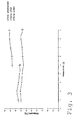
Figur 3 zeigt anhand einer vergleichenden Darstellung die Verbesserung, die mit dem erfindungsgemässen Verfahren erreichbar ist.FIG. 3 shows the improvement based on a comparative illustration can be achieved with the method according to the invention.
Gereinigt wurde ein wasserfreies Butterfett (= Fettsäuregemisch). Verglichen
wurde jeweils der Klarpunkt
Es wurden insgesamt 8 Proben von Butterfett kristallisert und die erzielte Verbesserung der Eigenschaft der Proben, insbesondere Erhöhung des Schmelzpunktes, wurde anhand des Klarpunktes der abgeschiedenen Kristallschicht festgestellt. Es ist bekannt, dass ein höherer Klarpunkt mit einer günstigeren Fettsäurezusammensetzung korreliert. Zum Gasschwitzen wurde Luft eingesetzt.A total of 8 samples of butterfat were crystallized and the one obtained Improvement of the property of the samples, in particular increase in the Melting point, was based on the clear point of the deposited Crystal layer found. It is known that a higher clear point with a correlated favorable fatty acid composition. For gas sweating Air used.
Das eingesetzte wasserfreie Butterfett besass vor der Reinigung einen Klarpunkt von 36 °C. Durch die eingesetzte dynamische Kristallisation mittels Fallfilm erhöhte sich der Klarpunkt des Butterfetts auf ca. 43 bis 44 °C (Kurve a).The anhydrous butterfat used had one before cleaning Clear point of 36 ° C. Due to the dynamic crystallization used Fall film increased the clarity of the butter fat to about 43 to 44 ° C (curve a).
Anschliessend wurden die Proben 1 bis 4 konventionell geschwitzt. Zum
(konventionellen) Schwitzen, d.h. Erwärmung der abgeschiedenen
Kristallschicht durch das in den Wärmetauscherflächen zirkulierende
Wärmetransfermedium, wurde das Wärmetransfermedium während 20
Minuten auf einer Temperatur von 35 °C belassen. Ein längeres Schwitzen
wurde durch die geringe Haftung der Kristallschicht an den
Wärmetauscherflächen verhindert (Gefahr des Abrutschens der Schicht).
Nach dem Schwitzen wurde der Klarpunkt der Kristallschicht neuerlich
gemessen (Kurve b).
Der Vergleich der Kurve a (Versuche 1 bis 4) mit der Kurve b zeigt, dass
durch das bekannte Schwitzverfahren von innen (d.h. via der
Wärmetauscherflächen) der Klarpunkt um ca. 1.0 bis 1.2 °C erhöht werden
konnte.The comparison of curve a (
Zum Gasschwitzen wurde auf ca. 80 °C erwärmte Luft über die Kristallschicht
geleitet (Versuche 5 bis 8). Während dieses Vorgangs wurde die Temperatur
des flüssigen Wärmetransfermediums auf ca. 15 °C gehalten, sodass die
Kristallschicht an den Wärmetauscherflächen gut haftete und ein Abrutschen
verhindert wurde. Das Gasschwitzen wurde eingestellt, sobald praktisch keine
Schmelze von der Kristallschicht mehr abtropfte (nach ca. 1 Stunde).Air was heated to about 80 ° C for gas sweating over the crystal layer
conducted (
Der Vergleich der Kurve a (Versuche 5 bis 8) mit der Kurve c (Gasschwitzen)
zeigt, dass durch das erfindungsgemässe, von aussen durch eine Gasphase
induzierte Schwitzverfahren der Klarpunkt um ca. 4 °C erhöht werden konnte.
Dieses im Vergleich zum bekannten Schwitzverfahren wesentlich bessere
Ergebnis war überraschend und unerwartet. Comparison of curve a (
Vorteilhaft eignet sich das neue Verfahren zur Reinigung von Acrylsäure, Metacrylsäure, Abwasser, Methyldiphenylisozyanat (MDI), Toluoldiisozyanat (TDI), Caprolactam, Benzoesäure, Bisphenol-A-, Nitrochlorbenzol, geradkettige und verzweigte Fettsäure, Hydrazin, Phenole wie para-, meta und ortho-Kresol, 2.6 und 3,5-Dimethylphenol, Naphthol und o,o-Diphenol, chlorierte Kohlenwasserstoffe wie Dichlorbenzol und Nitrochlorbenzol, Naphthalin, 1- 2-Methylnaphthalin, Acenaphthen, Fluoren, Phenanthren, Adipinsäuredinitril, Hexamethylendiamin, Lactide (Polylactide), Chlorpyrifos, Fettsäuregemische, Butterfett sowie Paraffine ab C17.The new process is advantageously suitable for the purification of acrylic acid, methacrylic acid, waste water, methyl diphenyl isocyanate (MDI), toluenediisocyanate (TDI), caprolactam, benzoic acid, bisphenol A, nitrochlorobenzene, straight-chain and branched fatty acid, hydrazine, phenols such as para, meta and ortho-cresol, 2,6 and 3,5-dimethylphenol, naphthol and o, o-diphenol, chlorinated hydrocarbons such as dichlorobenzene and nitrochlorobenzene, naphthalene, 1- 2-methylnaphthalene, acenaphthene, fluorene, phenanthrene, adiponitrile, hexamethylenediamine, lactide (polylactide) Chlorpyrifos, fatty acid mixtures, butterfat and paraffins from C 17 .
Das erfindungsgemässe Verfahren lässt sich bei allen Kristallisatortypen ( z.B. vom Typ Fallfilm, volldurchströmtes Rohr, Kristallisator mit flachen, z.B. doppelwandigen, Wärmetauscherflächen) einsetzen, welche ein dynamisches oder ein statischen Kristallisationsverfahren anwenden und die zu reinigende Verbindung als Kristallschicht auf Wärmetauscherflächen abgeschieden wird. Bestehende Kristallisatoren können mit geringem Aufwand nachgerüstet werden, um die Anwendung des erfindungsgemässen Gasschwitzens zu ermöglichen.The method according to the invention can be used with all crystallizer types (e.g. falling film type, fully flowed tube, crystallizer with flat, e.g. double-walled, heat exchanger surfaces), which are dynamic or use a static crystallization process and the one to be cleaned Compound is deposited as a crystal layer on heat exchanger surfaces. Existing crystallizers can be retrofitted with little effort be to the application of gas sweating according to the invention enable.
Claims (21)
e) dass zum wenigstens teilweise Schmelzen der gebildeten Kristallschicht wenigstens zeitweise ein Gasstrom eines gasförmigen Wärmetransfermediums über die Kristallschicht geleitet wird, wobei der Gasstrom vorgängig auf eine Temperatur erwärmt wird, welche höher als die Schmelztemperatur der Kristallschicht ist.Process for the separation or purification of dissolved, molten or liquid compounds or compound mixtures by means of fractional crystallization, in which process
e) that at least partially a gas stream of a gaseous heat transfer medium is passed over the crystal layer for at least partial melting of the crystal layer formed, the gas stream being previously heated to a temperature which is higher than the melting temperature of the crystal layer.
Priority Applications (1)
| Application Number | Priority Date | Filing Date | Title |
|---|---|---|---|
| EP99810752A EP1078669A1 (en) | 1999-08-23 | 1999-08-23 | Process and crystallizer for purifying materials or mixtures thereof |
Applications Claiming Priority (1)
| Application Number | Priority Date | Filing Date | Title |
|---|---|---|---|
| EP99810752A EP1078669A1 (en) | 1999-08-23 | 1999-08-23 | Process and crystallizer for purifying materials or mixtures thereof |
Publications (1)
| Publication Number | Publication Date |
|---|---|
| EP1078669A1 true EP1078669A1 (en) | 2001-02-28 |
Family
ID=8242988
Family Applications (1)
| Application Number | Title | Priority Date | Filing Date |
|---|---|---|---|
| EP99810752A Withdrawn EP1078669A1 (en) | 1999-08-23 | 1999-08-23 | Process and crystallizer for purifying materials or mixtures thereof |
Country Status (1)
| Country | Link |
|---|---|
| EP (1) | EP1078669A1 (en) |
Cited By (11)
| Publication number | Priority date | Publication date | Assignee | Title |
|---|---|---|---|---|
| US6670501B1 (en) * | 1997-07-12 | 2003-12-30 | Lucite International Uk Limited | Process for the production of methyl methacrylate |
| EP2599770A1 (en) | 2011-12-02 | 2013-06-05 | Bayer Intellectual Property GmbH | Method for producing isocyanates |
| CN104208900A (en) * | 2014-09-11 | 2014-12-17 | 江苏华伦化工有限公司 | Crystal catcher applied to acid anhydrides |
| CN105107223A (en) * | 2015-10-15 | 2015-12-02 | 贺源 | Crystallizing device and method |
| CN106701314A (en) * | 2017-02-17 | 2017-05-24 | 无锡市新耀生物工程技术有限公司 | Fish oil winterizing, fractioning, crystallizing and growing reaction tank |
| CN110272376A (en) * | 2019-07-19 | 2019-09-24 | 中冶焦耐(大连)工程技术有限公司 | A kind of operating method of carbazole purifying technique, system and system |
| CN111544921A (en) * | 2020-06-29 | 2020-08-18 | 天津乐科节能科技有限公司 | Self-backheating continuous melting crystallization system and method |
| CN112322350A (en) * | 2020-11-05 | 2021-02-05 | 中国科学院山西煤炭化学研究所 | Method for preparing high enthalpy value phase-change wax from Fischer-Tropsch synthesis product |
| CN113754530A (en) * | 2020-06-02 | 2021-12-07 | 中国石油化工股份有限公司 | Method for purifying adipic acid |
| CN114671768A (en) * | 2022-04-22 | 2022-06-28 | 上海东庚化工技术有限公司 | Industrial purification method of hexamethylene diamine |
| CN115400451A (en) * | 2022-08-12 | 2022-11-29 | 上海东庚化工技术有限公司 | Dynamic falling film crystallizer |
Citations (2)
| Publication number | Priority date | Publication date | Assignee | Title |
|---|---|---|---|---|
| US3621664A (en) * | 1967-04-14 | 1971-11-23 | Buchs Metallwerk Ag | Fractional crystallization process |
| US5700435A (en) * | 1994-12-08 | 1997-12-23 | Sulzer Chemtech Ag | Method and apparatus for separating a substance from a liquid mixture by fractional crystallization |
-
1999
- 1999-08-23 EP EP99810752A patent/EP1078669A1/en not_active Withdrawn
Patent Citations (2)
| Publication number | Priority date | Publication date | Assignee | Title |
|---|---|---|---|---|
| US3621664A (en) * | 1967-04-14 | 1971-11-23 | Buchs Metallwerk Ag | Fractional crystallization process |
| US5700435A (en) * | 1994-12-08 | 1997-12-23 | Sulzer Chemtech Ag | Method and apparatus for separating a substance from a liquid mixture by fractional crystallization |
Cited By (19)
| Publication number | Priority date | Publication date | Assignee | Title |
|---|---|---|---|---|
| US6670501B1 (en) * | 1997-07-12 | 2003-12-30 | Lucite International Uk Limited | Process for the production of methyl methacrylate |
| EP2599770A1 (en) | 2011-12-02 | 2013-06-05 | Bayer Intellectual Property GmbH | Method for producing isocyanates |
| DE102011087654A1 (en) | 2011-12-02 | 2013-06-06 | Bayer Materialscience Aktiengesellschaft | Process for the preparation of isocyanates |
| US8765991B2 (en) | 2011-12-02 | 2014-07-01 | Bayer Intellectual Property Gmbh | Process for the preparation of isocyanates |
| CN104208900A (en) * | 2014-09-11 | 2014-12-17 | 江苏华伦化工有限公司 | Crystal catcher applied to acid anhydrides |
| CN105107223A (en) * | 2015-10-15 | 2015-12-02 | 贺源 | Crystallizing device and method |
| CN106701314A (en) * | 2017-02-17 | 2017-05-24 | 无锡市新耀生物工程技术有限公司 | Fish oil winterizing, fractioning, crystallizing and growing reaction tank |
| CN106701314B (en) * | 2017-02-17 | 2023-10-27 | 无锡市新耀生物工程技术有限公司 | Crystal growing reaction tank for winterization, fractionation and crystallization of fish oil |
| CN110272376A (en) * | 2019-07-19 | 2019-09-24 | 中冶焦耐(大连)工程技术有限公司 | A kind of operating method of carbazole purifying technique, system and system |
| CN110272376B (en) * | 2019-07-19 | 2024-01-30 | 中冶焦耐(大连)工程技术有限公司 | Carbazole purification process, carbazole purification system and operation method of carbazole purification system |
| CN113754530B (en) * | 2020-06-02 | 2023-09-29 | 中国石油化工股份有限公司 | Method for purifying adipic acid |
| CN113754530A (en) * | 2020-06-02 | 2021-12-07 | 中国石油化工股份有限公司 | Method for purifying adipic acid |
| CN111544921A (en) * | 2020-06-29 | 2020-08-18 | 天津乐科节能科技有限公司 | Self-backheating continuous melting crystallization system and method |
| CN111544921B (en) * | 2020-06-29 | 2020-10-16 | 天津乐科节能科技有限公司 | Self-backheating continuous melting crystallization system and method |
| CN112322350B (en) * | 2020-11-05 | 2021-12-07 | 中国科学院山西煤炭化学研究所 | Method for preparing high enthalpy value phase-change wax from Fischer-Tropsch synthesis product |
| CN112322350A (en) * | 2020-11-05 | 2021-02-05 | 中国科学院山西煤炭化学研究所 | Method for preparing high enthalpy value phase-change wax from Fischer-Tropsch synthesis product |
| CN114671768A (en) * | 2022-04-22 | 2022-06-28 | 上海东庚化工技术有限公司 | Industrial purification method of hexamethylene diamine |
| CN114671768B (en) * | 2022-04-22 | 2023-09-12 | 上海东庚化工技术有限公司 | Industrial purifying method for hexamethylenediamine |
| CN115400451A (en) * | 2022-08-12 | 2022-11-29 | 上海东庚化工技术有限公司 | Dynamic falling film crystallizer |
Similar Documents
| Publication | Publication Date | Title |
|---|---|---|
| DE1769123B2 (en) | METHOD AND DEVICE FOR THE SEPARATION OF SUBSTANCES FROM A LIQUID MIXTURE BY FRACTIONAL CRYSTALLIZATION | |
| EP1078669A1 (en) | Process and crystallizer for purifying materials or mixtures thereof | |
| EP0614688B1 (en) | Apparatus for generating seed crystals in melts and crystallisation plant including such an apparatus | |
| DE69726041T2 (en) | Process for dry fractionation of oils and fats | |
| DE1794084C3 (en) | Device for the continuous recovery of crystals from a melt or solution | |
| DE3517386C2 (en) | ||
| EP0766985B1 (en) | Process and device for the separation of liquid eutectic mixtures by crystallisation on cooling surfaces | |
| EP1249174B1 (en) | Process and apparatus for continuous treatment of processed fatty masses | |
| EP0065775A2 (en) | Process and apparatus for continuous evaporative crystallisation | |
| DE1793345B1 (en) | Method and device for the purification of crystallizable organic compounds | |
| EP1038451A2 (en) | Method for operating a pasteurization plant | |
| EP0488953B1 (en) | Apparatus for separating material from a liquid mixture by cristallization | |
| EP0085791A1 (en) | Process and device for the separation of a liquid mixture by fractionated crystallisation | |
| DE3029302A1 (en) | METHOD FOR THE CONTINUOUS CLEANING OF RAW, HIGH-MELTING, HIGH-SENSING ORGANIC COMPOUNDS | |
| DE2530481A1 (en) | Batch crystalliser for prodn. of large crystals - with the soln. in vertical tubes externally cooled | |
| DE19536792A1 (en) | Process for the separation of substances from a liquid mixture by crystallization | |
| DE3426880A1 (en) | CRYSTAL CLEANING DEVICE | |
| DE10225075A1 (en) | Continuous post-condensation of plastic granules to increase viscosity involves continuous agitation of heated granules under vacuum during passage of a reactor | |
| DE3827455C2 (en) | ||
| EP1144169B1 (en) | Device and method for treating plastic material | |
| DE3209747C2 (en) | Device for the production of granules from a melt | |
| EP0492149B1 (en) | Process and apparatus for cleaning chemical substances | |
| DE1286507B (en) | Process for concentrating a multi-component liquid material | |
| DE19637380C1 (en) | Process for the preparation of hydroxipivalic acid neopentyl glycol ester granules | |
| DE19781525B4 (en) | Process for the preparation of granules of a thermolabile material and apparatus for carrying out this process |
Legal Events
| Date | Code | Title | Description |
|---|---|---|---|
| PUAI | Public reference made under article 153(3) epc to a published international application that has entered the european phase |
Free format text: ORIGINAL CODE: 0009012 |
|
| AK | Designated contracting states |
Kind code of ref document: A1 Designated state(s): AT BE CH CY DE DK ES FI FR GB GR IE IT LI LU MC NL PT SE |
|
| AX | Request for extension of the european patent |
Free format text: AL;LT;LV;MK;RO;SI |
|
| AKX | Designation fees paid | ||
| REG | Reference to a national code |
Ref country code: DE Ref legal event code: 8566 |
|
| STAA | Information on the status of an ep patent application or granted ep patent |
Free format text: STATUS: THE APPLICATION IS DEEMED TO BE WITHDRAWN |
|
| 18D | Application deemed to be withdrawn |
Effective date: 20010829 |