EP1078356B1 - Apparatus for trimming dye coated on a recordable disc substrate and related method - Google Patents
Apparatus for trimming dye coated on a recordable disc substrate and related method Download PDFInfo
- Publication number
- EP1078356B1 EP1078356B1 EP99919479A EP99919479A EP1078356B1 EP 1078356 B1 EP1078356 B1 EP 1078356B1 EP 99919479 A EP99919479 A EP 99919479A EP 99919479 A EP99919479 A EP 99919479A EP 1078356 B1 EP1078356 B1 EP 1078356B1
- Authority
- EP
- European Patent Office
- Prior art keywords
- during production
- optical memory
- substrate during
- dye coated
- trimming
- Prior art date
- Legal status (The legal status is an assumption and is not a legal conclusion. Google has not performed a legal analysis and makes no representation as to the accuracy of the status listed.)
- Expired - Lifetime
Links
- 239000000758 substrate Substances 0.000 title claims abstract description 103
- 238000009966 trimming Methods 0.000 title claims abstract description 64
- 238000000034 method Methods 0.000 title claims abstract description 51
- 230000003287 optical effect Effects 0.000 claims abstract description 76
- 238000004519 manufacturing process Methods 0.000 claims abstract description 47
- 239000006227 byproduct Substances 0.000 claims abstract description 24
- 230000008569 process Effects 0.000 claims abstract description 14
- 239000012530 fluid Substances 0.000 claims description 22
- IJGRMHOSHXDMSA-UHFFFAOYSA-N Atomic nitrogen Chemical compound N#N IJGRMHOSHXDMSA-UHFFFAOYSA-N 0.000 claims description 19
- XKRFYHLGVUSROY-UHFFFAOYSA-N Argon Chemical compound [Ar] XKRFYHLGVUSROY-UHFFFAOYSA-N 0.000 claims description 12
- CURLTUGMZLYLDI-UHFFFAOYSA-N Carbon dioxide Chemical compound O=C=O CURLTUGMZLYLDI-UHFFFAOYSA-N 0.000 claims description 12
- VNWKTOKETHGBQD-UHFFFAOYSA-N methane Chemical compound C VNWKTOKETHGBQD-UHFFFAOYSA-N 0.000 claims description 12
- 229910052757 nitrogen Inorganic materials 0.000 claims description 7
- UGFAIRIUMAVXCW-UHFFFAOYSA-N Carbon monoxide Chemical compound [O+]#[C-] UGFAIRIUMAVXCW-UHFFFAOYSA-N 0.000 claims description 6
- 229910052786 argon Inorganic materials 0.000 claims description 6
- QVGXLLKOCUKJST-UHFFFAOYSA-N atomic oxygen Chemical compound [O] QVGXLLKOCUKJST-UHFFFAOYSA-N 0.000 claims description 6
- 239000001569 carbon dioxide Substances 0.000 claims description 6
- 229910002092 carbon dioxide Inorganic materials 0.000 claims description 6
- 229910002091 carbon monoxide Inorganic materials 0.000 claims description 6
- 239000000835 fiber Substances 0.000 claims description 6
- 239000001307 helium Substances 0.000 claims description 6
- 229910052734 helium Inorganic materials 0.000 claims description 6
- SWQJXJOGLNCZEY-UHFFFAOYSA-N helium atom Chemical compound [He] SWQJXJOGLNCZEY-UHFFFAOYSA-N 0.000 claims description 6
- 239000011261 inert gas Substances 0.000 claims description 6
- 239000007788 liquid Substances 0.000 claims description 6
- 239000001301 oxygen Substances 0.000 claims description 6
- 229910052760 oxygen Inorganic materials 0.000 claims description 6
- 239000004065 semiconductor Substances 0.000 claims description 6
- JCXJVPUVTGWSNB-UHFFFAOYSA-N nitrogen dioxide Inorganic materials O=[N]=O JCXJVPUVTGWSNB-UHFFFAOYSA-N 0.000 claims description 5
- 238000007493 shaping process Methods 0.000 claims description 4
- 239000007789 gas Substances 0.000 claims description 3
- 238000007599 discharging Methods 0.000 claims 8
- 239000006185 dispersion Substances 0.000 claims 2
- 239000000975 dye Substances 0.000 description 33
- 239000002904 solvent Substances 0.000 description 10
- 238000004140 cleaning Methods 0.000 description 5
- 239000004922 lacquer Substances 0.000 description 5
- 229920000515 polycarbonate Polymers 0.000 description 5
- 239000004417 polycarbonate Substances 0.000 description 5
- 230000001681 protective effect Effects 0.000 description 5
- 238000005406 washing Methods 0.000 description 5
- 230000000694 effects Effects 0.000 description 3
- 238000012423 maintenance Methods 0.000 description 3
- 239000000047 product Substances 0.000 description 3
- 231100000331 toxic Toxicity 0.000 description 3
- 230000002588 toxic effect Effects 0.000 description 3
- XAGFODPZIPBFFR-UHFFFAOYSA-N aluminium Chemical compound [Al] XAGFODPZIPBFFR-UHFFFAOYSA-N 0.000 description 2
- 229910052782 aluminium Inorganic materials 0.000 description 2
- 238000013459 approach Methods 0.000 description 2
- 230000004888 barrier function Effects 0.000 description 2
- 239000010408 film Substances 0.000 description 2
- 238000001755 magnetron sputter deposition Methods 0.000 description 2
- 230000000873 masking effect Effects 0.000 description 2
- 238000012986 modification Methods 0.000 description 2
- 230000004048 modification Effects 0.000 description 2
- 238000012545 processing Methods 0.000 description 2
- 230000005855 radiation Effects 0.000 description 2
- 238000012360 testing method Methods 0.000 description 2
- 239000010409 thin film Substances 0.000 description 2
- BQCADISMDOOEFD-UHFFFAOYSA-N Silver Chemical compound [Ag] BQCADISMDOOEFD-UHFFFAOYSA-N 0.000 description 1
- 238000010521 absorption reaction Methods 0.000 description 1
- 239000004411 aluminium Substances 0.000 description 1
- 239000011248 coating agent Substances 0.000 description 1
- 238000000576 coating method Methods 0.000 description 1
- 238000011109 contamination Methods 0.000 description 1
- 238000001816 cooling Methods 0.000 description 1
- 230000001186 cumulative effect Effects 0.000 description 1
- 238000000151 deposition Methods 0.000 description 1
- 230000008021 deposition Effects 0.000 description 1
- 238000009792 diffusion process Methods 0.000 description 1
- 238000001035 drying Methods 0.000 description 1
- 239000000428 dust Substances 0.000 description 1
- 230000006870 function Effects 0.000 description 1
- PCHJSUWPFVWCPO-UHFFFAOYSA-N gold Chemical compound [Au] PCHJSUWPFVWCPO-UHFFFAOYSA-N 0.000 description 1
- 229910052737 gold Inorganic materials 0.000 description 1
- 239000010931 gold Substances 0.000 description 1
- 239000000463 material Substances 0.000 description 1
- 239000001007 phthalocyanine dye Substances 0.000 description 1
- 229910052709 silver Inorganic materials 0.000 description 1
- 239000004332 silver Substances 0.000 description 1
- 238000004528 spin coating Methods 0.000 description 1
- 239000000126 substance Substances 0.000 description 1
Images
Classifications
-
- B—PERFORMING OPERATIONS; TRANSPORTING
- B23—MACHINE TOOLS; METAL-WORKING NOT OTHERWISE PROVIDED FOR
- B23K—SOLDERING OR UNSOLDERING; WELDING; CLADDING OR PLATING BY SOLDERING OR WELDING; CUTTING BY APPLYING HEAT LOCALLY, e.g. FLAME CUTTING; WORKING BY LASER BEAM
- B23K26/00—Working by laser beam, e.g. welding, cutting or boring
- B23K26/14—Working by laser beam, e.g. welding, cutting or boring using a fluid stream, e.g. a jet of gas, in conjunction with the laser beam; Nozzles therefor
- B23K26/1462—Nozzles; Features related to nozzles
- B23K26/1464—Supply to, or discharge from, nozzles of media, e.g. gas, powder, wire
- B23K26/147—Features outside the nozzle for feeding the fluid stream towards the workpiece
-
- B—PERFORMING OPERATIONS; TRANSPORTING
- B23—MACHINE TOOLS; METAL-WORKING NOT OTHERWISE PROVIDED FOR
- B23K—SOLDERING OR UNSOLDERING; WELDING; CLADDING OR PLATING BY SOLDERING OR WELDING; CUTTING BY APPLYING HEAT LOCALLY, e.g. FLAME CUTTING; WORKING BY LASER BEAM
- B23K26/00—Working by laser beam, e.g. welding, cutting or boring
- B23K26/14—Working by laser beam, e.g. welding, cutting or boring using a fluid stream, e.g. a jet of gas, in conjunction with the laser beam; Nozzles therefor
- B23K26/1462—Nozzles; Features related to nozzles
-
- B—PERFORMING OPERATIONS; TRANSPORTING
- B23—MACHINE TOOLS; METAL-WORKING NOT OTHERWISE PROVIDED FOR
- B23K—SOLDERING OR UNSOLDERING; WELDING; CLADDING OR PLATING BY SOLDERING OR WELDING; CUTTING BY APPLYING HEAT LOCALLY, e.g. FLAME CUTTING; WORKING BY LASER BEAM
- B23K26/00—Working by laser beam, e.g. welding, cutting or boring
- B23K26/351—Working by laser beam, e.g. welding, cutting or boring for trimming or tuning of electrical components
-
- G—PHYSICS
- G11—INFORMATION STORAGE
- G11B—INFORMATION STORAGE BASED ON RELATIVE MOVEMENT BETWEEN RECORD CARRIER AND TRANSDUCER
- G11B7/00—Recording or reproducing by optical means, e.g. recording using a thermal beam of optical radiation by modifying optical properties or the physical structure, reproducing using an optical beam at lower power by sensing optical properties; Record carriers therefor
- G11B7/24—Record carriers characterised by shape, structure or physical properties, or by the selection of the material
- G11B7/26—Apparatus or processes specially adapted for the manufacture of record carriers
Definitions
- the present invention relates to an apparatus and process for cleaning selected areas of an optical memory disc substrate during production of an optical memory disc, and more particularly, to a laser trimming system for cleaning dye from the outer edge of a disc substrate used in a CD-R or DVD-R manufacturing process.
- the typical structure of a CD-R or DVD-R disc includes an energy absorbing dye layer deposited directly over a polymeric substrate.
- a thin film reflective layer is typically formed directly over the dye layer, usually via magnetron sputtering. This reflective layer also functions as a barrier layer to isolate the dye layer.
- a radiation curable protective lacquer is applied directly over the reflective layer.
- the structure may tend to delaminate, starting at the outermost edge of the substrate.
- the protective lacquer must bond directly to the substrate surface at the outer edge of the substrate. Additionally, allowing the protective lacquer to bond directly to the polymeric substrate provides an effective barrier to atmospheric contamination of the energy absorbing and reflective layers. Simple masking can be used to shield the outer edge of the substrate during deposition of the reflective layer. However, masking is not practical during the spin coating step used to apply the dye layer. Some means of brimming the dye at the outer edge of the disc is therefore required, as removal of the dye at the outer edge of the disc is advantageous in preventing failure of the coated structure.
- Typical approaches to trimming the dye at the outer edge of the disc include solvent "washing” and mechanical trimming operations. Solvent washing, however, requires precise control over the application and spin drying process. In addition, the initial cost of solvent, plus the cost of contaminated solvent disposal are substantial. Mechanical edge trimming is relatively easy to implement. However, debris generation, tooling wear, and proper cooling must be considered. Therefore, it has been found desirable to provide an edge trimming system for an optical memory disc which avoids these limitations and is easily implemented, reliable, and economical.
- the apparatus comprise a turntable where a CD is placed; a lens system to irradiate laser light to the circumferentiual part of the CD; and an air nozzle to blow air on the irradiated part of the CD to remove the powdery dust.
- the air nozzle is detached from the lens system which is the only moving part in the process where the laser light is irradiated.
- An additional object of the present invention is to provide an improved apparatus and method for selectively trimming dye from a recordable optical memory disc substrate which reduces operating expenses by eliminating the use of washing solvents and toxic solvent disposal.
- Another object of this invention is to provide an improved apparatus and method for selectively trimming dye from a recordable optical memory disc substrate which reduces maintenance expenses.
- a further object of this invention is to provide an improved apparatus and method for selectively trimming dye from a recordable optical memory disc substrate which improves product quality and reliability.
- an apparatus and method for selectively trimming a substrate for a recordable optical memory disc which includes a substrate rotation assembly for rotating the disc substrate, an optical energy generation assembly, an optical assembly which receives the optical energy and directs a shaped beam directly upon the rotatable substrate to trim the dye coated thereon, and a byproduct removal assembly to direct the process byproducts away from the disc substrate for subsequent collection by a byproduct collection system.
- an optical energy generation assembly in the form of a commercially available multi-diode semiconductor laser array produces the optical energy and supplies the energy to the optical assembly.
- the optical assembly of the present invention includes a fiber optic delivery system which receives the energy from the optical energy generation assembly and a focusing system for shaping the beam and directing the beam directly upon the rotatable substrate to trim the dye coated thereon.
- a laser In order to trim dye during production of optical disc substrates, such as optical disc substrates used in a CD-R and DVD-R process, a laser is utilized which has a wavelength between approximately 450 and 800 nm and has a maximum power of approximately 12 watts.
- the laser beam is shaped by the focusing optic system to have a diameter of approximately 0.5 to 1.5 mm and is collimated within a length of between approximately 2 to 5 mm.
- a byproduct removal assembly is utilized which is in the form of a fluidic jet assembly attached to the focusing optic system so as to extend at an angle of between approximately 5° to 80° toward a byproduct collection unit.
- the fluid discharged from the fluidic jet assembly can be any inert gas, such as nitrogen, argon or helium.
- air can be discharged from the jet as well as cryogenic liquids, such as carbon dioxide and nitrogen.
- a reactive gas such as oxygen, carbon monoxide or methane, can be also discharged from the fluidic jet assembly.
- the trimming apparatus and method of the present invention reduces operating expenses, by eliminating the cost of edge washing solvent and toxic solvent disposal, reduces maintenance expenses, due to its simple and reliable nature, and improves product quality and reliability, due to its superior performance.
- the typical structure of a CD-R or DVD-R optical memory disc includes an energy absorbing dye layer 10 deposited directly over a polymeric substrate 12.
- a thin film reflective layer such as gold, silver or aluminum, is formed directly over the dye layer, usually via magnetron sputtering.
- a radiation curable protective lacquer is applied directly over the reflective film layer.
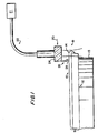
- the present invention provides an apparatus and method for trimming the dye coated at the outer edge of the polymeric substrate, as is represented by the outer edge dye portion 14 in Fig. 1.
- trimming of the dye at the outer edge of the substrate is advantageous in preventing coating stack curl back, edge diffusion and subsequent failure of the optical memory disc.
- the optical memory disc 16 including a polycarbonate substrate 12 and dye layer 10 is positioned on a substrate rotation assembly 15 which rotates the disc substrate. While the disc substrate is rotated, an optical assembly 20 receives laser energy and directs a shaped laser beam (see 19 in Fig. 1) directly upon the outer edge dye portion 14 of the rotatable substrate to trim the outer edge dye coated thereon.
- a laser energy generation assembly 21 preferably in the form of a multi-diode semiconductor laser array, produces the laser energy and supplies the laser energy to the optical assembly 20.
- the optical assembly 20 includes a fiber optic delivery system 22 which receives the laser energy from the laser generation assembly 21 and passes the laser energy to the focusing optic system 24 of the optical assembly 20.
- the focusing optic system 24 shapes the laser beam and directs the laser beam directly upon the outer edge of the rotatable substrate to trim the outer edge dye portion 14 coated thereon.
- the wavelength of the laser beam can be optimized to suit the requirements of the media being used. Moreover, it has been found that laser wavelengths of approximately 550 and 720 nm are preferred for trimming the outer edge dye portion 14 from an optical memory disc substrate used respectively to produce a DVD-R optical memory disc and a CD-R optical memory disc. However, suitable cleaning of the dye from the outer edge of CD-R disc substrates has been accomplished by utilizing a laser beam having a wavelength of approximately 690 nm with a maximum power of approximately 12 watts. However, acceptable trimming results have been attained with a laser power between approximately 6 to 8 watts.
- Results range from complete removal of the dye to a fusing of the dye with the substrate material.
- a polycarbonate substrate coated with phthalocyanine dye produced by Ciba Specialty Chemicals was effectively edgetrimmed using a 10 watt, 690 nm laser beam directed at the rotating substrate for approximately 4 seconds.
- the laser beam was shaped by the focusing optic system 24 to have a diameter of approximately 1 mm and was collimated over a length of approximately 3 mm. The effectiveness of the procedure was verified by subsequent adhesion testing.
- a byproduct removing assembly 26 is attached to the optic assembly 20.
- the byproduct removal assembly 26 includes an orifice 28 which is mounted at an angle of approximately 45° toward the outer edge of the disc substrate.
- the byproduct removal assembly 26 is a fluidic jet.
- the fluid discharged from the fluidic jet can be any inert gas, such as nitrogen, argon or helium.
- air can be discharged from the fluidic jet as well as cryogenic liquids, such as nitrogen and carbon dioxide.
- the fluid discharged from the fluidic jet can be a reactive gas, such as oxygen, methane or carbon monoxide.
- the laser beam had no effect on uncoated polycarbonate.
- the surface modification effect resulting therefrom was primarily due to energy absorption by the dye.
- the power requirements set forth above achieved complete removal of the dye, and a slight texturing of the polycarbonate surface. This texturing further improves adhesion of the protective lacquer to the polycarbonate substrate.
- the method and apparatus of the present invention reduces operating expenses, by eliminating the cost of edge washing solvents and toxic solvent disposal, reduces maintenance expenses, due to the simple and reliable nature of the approach, and improves product quality and reliability, due to superior edge cleaning performance.
Landscapes
- Engineering & Computer Science (AREA)
- Physics & Mathematics (AREA)
- Optics & Photonics (AREA)
- Plasma & Fusion (AREA)
- Mechanical Engineering (AREA)
- Manufacturing & Machinery (AREA)
- Manufacturing Optical Record Carriers (AREA)
- Ink Jet Recording Methods And Recording Media Thereof (AREA)
- Printing Methods (AREA)
Abstract
Description
Claims (41)
- An apparatus for trimming dye coated on a recordable disc substrate during production of an optical memory disc comprising:substrate rotation means (15) for rotating the disc substrate;an optical assembly (20) having means for receiving laser energy and for directing said laser energy directly upon the rotatable substrate to trim the dye coated thereon and thereby produce byproducts of the trimming operation; andmeans (26) for removing the byproducts of the trimming operation from the substrate characterized in that said removing means are attached to said optical assembly.
- The apparatus for trimming dye coated on a recordable disc substrate during production of an optical memory disc of claim 1 and further comprising laser generation means for producing the laser energy and for supplying said laser energy to said laser energy receiving and directing means.
- The apparatus for trimming dye coated on a recordable disc substrate during production of an optical memory disc of claim 2 wherein said laser generation means is a multi-diode semi-conductor laser array.
- The apparatus for trimming dye coated on a recordable disc substrate during production of an optical memory disc of claim 2 wherein said laser energy receiving and directing means includes a fiber optic delivery system (22) receiving the laser energy from the laser generation means.
- The apparatus for trimming dye coated on a recordable disc substrate during production of an optical memory disc of claim 2 wherein said laser. energy receiving and directing means includes a focusing optic system (24) for shaping and collimating a laser beam and directing the laser beam directly upon the rotatable substrate to trim the dye coated thereon.
- The apparatus for trimming dye coated on a recordable disc substrate during production of an optical memory disc of claim 1 wherein said byproduct removing means is a fluidic jet for directing the process byproducts away from the rotatable disc substrate, said fluidic jet having an angularly disposed dispersion orifice (28) which is angularly displaced at an angle of between approximately 5° to 80°.
- The apparatus for trimming dye coated on a recordable disc substrate during production of an optical memory disc of claim 6 wherein the fluid discharged from said fluidic jet is an inert gas selected from the group consisting of nitrogen, argon and helium.
- The apparatus for trimming dye coated on a recordable disc substrate during production of an optical memory disc of claim 6 wherein the fluid discharged from said fluidic jet is air.
- The apparatus for trimming due coated on a recordable disc substrate during production of an optical memory disk of claim 6 wherein the fluid discharged from said fluidic jet is a cryogenic liquid selected from the group consisting of nitrogen and carbon dioxide.
- The apparatus for trimming dye coated on a recordable disc substrate during production of an optical memory disc of claim 6 wherein the fluid discharged from said fluidic jet is a reactive fluid.
- The apparatus for trimming dye coated on a recordable disc substrate during production of an optical memory disc of claim 10 wherein the reactive fluid is selected from the group consisting of oxygen, methane and carbon monoxide.
- The apparatus for trimming dye coated on a recordable disc substrate during production of an optical memory disc of claim 5 wherein the laser beam has a wavelength between approximately 450 and 800 nm, is collimated by said focusing optic system with a diameter of between approximately 0.5 to 1.5 mm, and is collimated within a length of between approximately 2 to 5 mm;
laser generation means for producing the laser energy and for supplying said laser energy to said laser energy receiving and directing means wherein the laser beam is produced with a maximum power of approximately 12 watts; and
means for removing the process byproducts from the substrate. - The apparatus for trimming dye coated on a recordable disc substrate during production of an optical memory disc of claim 12 wherein said laser energy generation means is a multi-diode semi-conductor laser array.
- The apparatus for trimming dye coated on a recordable disc substrate during production of an optical memory disc of claim 12 wherein said laser energy receiving and directing means includes a fiber optic delivery system receiving the laser ene gy from the laser generation means.
- The apparatus for trimming dye coated on a recordable disc substrate during production of an optical memory disc of claim 12 wherein said byproduct removing means is a fluidic jet for directing the process byproducts away from the substrate, said fluidic jet having an angularly disposed dispersion orifice which is angularly displaced at an angle of between approximately 5° to 80°.
- The apparatus for trimming dye coated on a recordable disc substrate during production of an optical memory disc of claim 15 wherein the fluid discharged from said fluidic jet is an inert gas selected from the group consisting of nitrogen, argon and helium.
- The apparatus for trimming dye coated on a recordable disc substrate during production of an optical memory disc of claim 15 wherein the fluid discharged from said fluidic jet is air.
- The apparatus for trimming dye coated on a recordable disc substrate during production of an optical memory disc of claim 15 wherein the fluid discharged from said fluidic jet is a cryogenic liquid selected from the group consisting of nitrogen and carbon dioxide.
- The apparatus for trimming dye coated on a recordable disc substrate during production of an optical memory disc of claim 15 wherein the fluid discharged from said fluidic jet is a reactive gas.
- The apparatus for trimming dye coated on a recordable disc substrate during production of an optical memory disc of claim 19 wherein the reactive fluid is selected from the group consisting of oxygen, methane and carbon monoxide.
- A method for trimming dye coated on a recordable disc substrate during production of an optical memory disc, said method comprising the steps of:rotating the disc substrate by means of substrate rotation means;receiving laser energy and directing the laser energy directly upon the disc substrate by means of an optical assembly to trim the dye coated thereon and thereby produce process byproducts; andremoving the process byproducts from the rotatable disc substrate, characterized in that said removing step is performed by removing means attached to said optical assembly.
- The method for trimming dye coated on a recordable disc substrate during production of an optical memory disc of claim 21 and further comprising the steps of producing the laser energy and supplying the laser energy to said optical assembly by means of laser energy generation means.
- The method for trimming dye coated on a recordable disc substrate during production of an optical memory disc of claim 22 wherein said laser energy generation means is a multi-diode semi-conductor laser array.
- The method for trimming dye coated on a recordable disc substrate during production thereof of claim 22 and further comprising the step of receiving the laser energy from the laser energy generation means by means of a fiber optic delivery system of said optical assembly.
- The method for trimming dye coated on recordable disc substrate during production of an optical memory disc of claim 21 and further comprising the steps of shaping and collimating the laser beam and directing the laser beam directly upon the rotatable disc substrate by means of a focusing optic system of the optic assembly to trim the dye coated thereon.
- The method for trimming dye coated on a recordable disc substrate during production of an optical memory disc of claim 21 and further comprising the step of removing the process byproducts from the substrate by means of a fluidic jet.
- The method for trimming dye coated on a recordable disc substrate during production of an optical memory disc of claim 26. and further comprising the step of discharging fluid from the fluidic jet which is an inert gas selected from the group consisting of nitrogen, argon and helium.
- The method for trimming dye coated on a recordable disc substrate during production of an optical memory disc of claim 26 and further comprising the step of discharging air from the fluidic jet.
- The method for trimming dye coated on a recordable disc substrate during production of an optical memory disc of claim 26 and further comprising the step of discharging a cryogenic liquid from the fluidic jet selected from the group consisting of nitrogen and carbon dioxide.
- The method for trimming dye coated on a recordable disc substrate during production of an optical memory disc of claim 26 and further comprising the step of discharging fluid from the fluidic jet which is a reactive fluid.
- The method for trimming dye coated on a recordable disc substrate during production of an optical memory disc of claim 30 wherein the reactive fluid is selected from the group consisting of oxygen, methane and carbon monoxide.
- The method for trimming dye coated on a recordable disc substrate during production of an optical memory disc of claim 21, said method further comprising the steps of:generating laser energy from a laser energy generation means with a maximum power of approximately 12 watts and supplying the laser energy to said optic assembly;shaping and collimating the laser beam in a focusing optic system of said optic assembly and directing the laser beam directly upon the rotatable substrate to trim the dye coated thereon and thereby produce process byproducts wherein the laser beam has a wavelength of between approximately 450 and 800 nm, is collimated by said focusing optic system with a diameter of between approximately 0.5 to 1.5 mm, and is collimated within a length of between approximately 2 to 5 mm.
- The method for trimming dye coated on a reeordable disc substrate during production of an optical memory disc of claim 32 wherein said laser energy generation means is a multi-diode semiconductor laser array.
- The method for trimming dye coated on a recordable disc substrate during production of an optical memory disc of claim 32 and further comprising the step of receiving the laser energy from the laser energy generation means by means of a fiber optic delivery system of said optic assembly.
- The method for trimming dye coated on a recordable disc substrate during production of an optical memory disc of claim 32 wherein the optic assembly is stationarily mounted.
- The method for trimming dye coated on a recordable disc substrate during production of an optical memory disc of claim 32 and further comprising the step of removing the process byproducts from the substrate by means of a fluidic jet.
- The method for trimming dye coated on a recordable disc substrate during production of an optical memory disc of claim 36 and further comprising the step of discharging fluid from said fluidic jet which is an inert gas selected from the group consisting of nitrogen, argon and helium.
- The method for trimming dye coated on a recordable disc substrate during production of an optical memory disc of claim 36 and further comprising the step of discharging air from said fluidic jet.
- The method for trimming dye coated on a recordable disk substrate during production of an optical memory disc of claim 36 and further comprising the step of discharging cryogenic liquid from said fluidic jet which is selected from the group consisting of nitrogen and carbon dioxide.
- The method for trimming dye coated on a recordable disc substrate during production of an optical memory disc of claim 36 and further comprising the step of discharging fluid from said fluidic jet which is a reactive fluid.
- The method for trimming dye coated on a recordable disc substrate during production of an optical memory disc of claim 40 wherein the reactive fluid is selected from the group consisting of oxygen, methane and carbon monoxide.
Applications Claiming Priority (3)
| Application Number | Priority Date | Filing Date | Title |
|---|---|---|---|
| US09/073,304 US6191384B1 (en) | 1998-05-05 | 1998-05-05 | Apparatus for trimming dye coated on a recordable disc substrate and related method |
| US73304 | 1998-05-05 | ||
| PCT/IB1999/000937 WO1999057721A1 (en) | 1998-05-05 | 1999-05-03 | Apparatus for trimming dye coated on a recordable disc substrate and related method |
Publications (2)
| Publication Number | Publication Date |
|---|---|
| EP1078356A1 EP1078356A1 (en) | 2001-02-28 |
| EP1078356B1 true EP1078356B1 (en) | 2003-04-16 |
Family
ID=22112953
Family Applications (1)
| Application Number | Title | Priority Date | Filing Date |
|---|---|---|---|
| EP99919479A Expired - Lifetime EP1078356B1 (en) | 1998-05-05 | 1999-05-03 | Apparatus for trimming dye coated on a recordable disc substrate and related method |
Country Status (6)
| Country | Link |
|---|---|
| US (2) | US6191384B1 (en) |
| EP (1) | EP1078356B1 (en) |
| AT (1) | ATE237860T1 (en) |
| CA (1) | CA2330290A1 (en) |
| DE (1) | DE69906962T2 (en) |
| WO (1) | WO1999057721A1 (en) |
Families Citing this family (7)
| Publication number | Priority date | Publication date | Assignee | Title |
|---|---|---|---|---|
| US6565928B2 (en) * | 1999-03-08 | 2003-05-20 | Tokyo Electron Limited | Film forming method and film forming apparatus |
| US6248974B1 (en) * | 2000-03-16 | 2001-06-19 | Callaway Golf Company | Method and apparatus for laser treatment of a golf ball |
| WO2005057165A2 (en) * | 2003-12-05 | 2005-06-23 | The Regents Of The University Of Michigan | Biodegradable/bioresorbable tissue augmentation/reconstruction device |
| ATE490838T1 (en) * | 2004-03-31 | 2010-12-15 | Nikon Corp | METHOD FOR PROCESSING ORGANIC CRYSTALS |
| US20090107519A1 (en) * | 2007-10-30 | 2009-04-30 | Sokudo Co., Ltd. | Method and system for chemically enhanced laser trimming of substrate edges |
| US9490975B1 (en) * | 2009-12-22 | 2016-11-08 | The Boeing Company | Information assurance for networked systems |
| DE102011075821A1 (en) * | 2011-05-13 | 2012-11-15 | Robert Bosch Gmbh | Brake disc and method for producing a brake disc |
Family Cites Families (57)
| Publication number | Priority date | Publication date | Assignee | Title |
|---|---|---|---|---|
| US3997344A (en) | 1974-07-05 | 1976-12-14 | American Can Company | Dry positive photopolymer imaging process involving heating and application of toner |
| US4038663A (en) * | 1975-09-23 | 1977-07-26 | U.S. Philips Corporation | Method of writing information with a modulated radiation beam onto an information storage medium and information storage medium particularly adapted to the method |
| JPS6010432A (en) * | 1983-06-30 | 1985-01-19 | Sentoraruteepu Eejienshii:Kk | Aluminium eliminating device for compact disc |
| US4656121A (en) | 1984-02-06 | 1987-04-07 | Ricoh Co., Ltd. | Optical information recording medium |
| US4538159A (en) | 1984-04-16 | 1985-08-27 | Eastman Kodak Company | Ceramic overcoated optical recording element |
| US4527173A (en) | 1984-04-16 | 1985-07-02 | Eastman Kodak Company | Erasable, reusable optical recording element and method |
| US4518551A (en) * | 1984-04-30 | 1985-05-21 | Rca Corporation | Method and apparatus for trimming and finishing the outer edge of a molded record |
| JPS61139956A (en) * | 1984-12-11 | 1986-06-27 | Matsushita Electric Ind Co Ltd | Manufacture of information carrier disk |
| US4740447A (en) | 1984-11-30 | 1988-04-26 | Nec Corporation | Optical recording medium |
| JPH083913B2 (en) | 1987-03-18 | 1996-01-17 | キヤノン株式会社 | Optical recording medium |
| DE3725134A1 (en) | 1987-07-29 | 1989-02-09 | Basf Ag | FLAECHENFOERMIGES, MULTILAYER, LASEROPTIC RECORDING MATERIAL |
| JPH01150256A (en) | 1987-12-07 | 1989-06-13 | Fuji Photo Film Co Ltd | Production of information recording medium |
| DE3802031A1 (en) | 1988-01-25 | 1989-07-27 | Hoechst Ag | MULTILAYERED RECORDING MATERIAL FOR OPTICAL INFORMATION |
| US5018128A (en) | 1988-02-05 | 1991-05-21 | Tandy Corporation | Apparatus and medium for recording erasable information |
| EP0328212A1 (en) | 1988-02-11 | 1989-08-16 | Koninklijke Philips Electronics N.V. | Method of manufacturing a metal matrix and a master disc suitable for the manufacture of matrices |
| US5171480A (en) | 1988-08-29 | 1992-12-15 | Matsushita Electric Industrial Co., Ltd. | Electrophotographic photosensitive member containing a conductive layer which comprises a resin and a conductive zinc oxide having a tetrapad structure |
| US5578415A (en) | 1988-09-12 | 1996-11-26 | Asahi Kasei Kogyo Kabushiki Kaisha | Optical recording materials, method for preparing the same and optical cards having the same |
| US5196231A (en) | 1988-12-28 | 1993-03-23 | Mitsui Toatsu Chemicals, Inc. | Optical recording media |
| EP0376231B1 (en) | 1988-12-28 | 1994-09-07 | MITSUI TOATSU CHEMICALS, Inc. | Optical recording media |
| JP2671141B2 (en) * | 1989-01-06 | 1997-10-29 | 富士写真フイルム株式会社 | Information recording medium and method of manufacturing the same |
| US5079061A (en) | 1989-02-27 | 1992-01-07 | Matsushita Electric Industrial Co., Ltd. | Optical storage media |
| US5185194A (en) | 1989-03-31 | 1993-02-09 | Ricoh Company, Ltd. | Heat-mode recording medium |
| JP2511147B2 (en) | 1989-07-06 | 1996-06-26 | パイオニア株式会社 | optical disk |
| JP2822531B2 (en) | 1990-01-29 | 1998-11-11 | ブラザー工業株式会社 | Magneto-optical recording medium and magneto-optical recording / erasing method |
| JPH03256240A (en) | 1990-03-06 | 1991-11-14 | Ricoh Co Ltd | Optical information recording medium |
| US5023167A (en) | 1990-03-08 | 1991-06-11 | Hoechst Celanese Corp. | Optical information card |
| JP3026586B2 (en) | 1990-07-20 | 2000-03-27 | 株式会社リコー | Optical information recording medium |
| US5487926A (en) | 1990-11-22 | 1996-01-30 | Tdk Corporation | Optical disk |
| CA2068618A1 (en) * | 1991-05-21 | 1992-11-22 | Tadahiko Mizukuki | Optical recording medium and production thereof |
| JPH0512715A (en) | 1991-07-03 | 1993-01-22 | Pioneer Electron Corp | Optical recording medium |
| US5455818A (en) | 1992-01-22 | 1995-10-03 | Brother Kogyo Kabushiki Kaisha | Optical recording medium |
| US5424106A (en) | 1992-04-17 | 1995-06-13 | Matsushita Electric Industrial Co., Ltd. | Optical information recording medium and method of designing its structure |
| EP0575176B1 (en) | 1992-06-18 | 1998-08-19 | Canon Kabushiki Kaisha | Optical recording medium, information recording method and information reproducing method |
| JP3160095B2 (en) | 1992-06-29 | 2001-04-23 | ティーディーケイ株式会社 | Recording / reproducing method for magneto-optical disk |
| US5549953A (en) | 1993-04-29 | 1996-08-27 | National Research Council Of Canada | Optical recording media having optically-variable security properties |
| JP2812181B2 (en) | 1993-06-17 | 1998-10-22 | 日本電気株式会社 | Optical information recording medium |
| JPH0714219A (en) * | 1993-06-28 | 1995-01-17 | Sony Corp | Apparatus and method for separating master for optical disk production |
| JPH07141693A (en) | 1993-09-22 | 1995-06-02 | Toshiba Corp | Information recording medium |
| US5424508A (en) * | 1994-01-06 | 1995-06-13 | Xerox Corporation | Laser ablation system |
| DE4409850C2 (en) | 1994-03-22 | 1999-05-12 | Fraunhofer Ges Forschung | Information storage unit |
| JPH07311979A (en) | 1994-03-24 | 1995-11-28 | Sanyo Electric Co Ltd | Optical recording medium and reproducing method therefor |
| US5631056A (en) | 1994-03-31 | 1997-05-20 | Victor Company Of Japan, Ltd. | Optical recording medium |
| JP2999916B2 (en) | 1994-03-31 | 2000-01-17 | ティーディーケイ株式会社 | Optical recording method and optical recording medium |
| JP3226418B2 (en) | 1994-05-26 | 2001-11-05 | キヤノン株式会社 | Recording method of thermal recording medium |
| JP3506491B2 (en) | 1994-06-23 | 2004-03-15 | Tdk株式会社 | Optical information media |
| EP0766862A1 (en) | 1994-06-23 | 1997-04-09 | Koninklijke Philips Electronics N.V. | Optical information carrier |
| JP3068416B2 (en) | 1994-08-26 | 2000-07-24 | 日本電気株式会社 | Information recording medium |
| JPH08124211A (en) | 1994-10-19 | 1996-05-17 | Fuji Xerox Co Ltd | Optical recording medium |
| KR0165299B1 (en) | 1994-11-11 | 1999-03-20 | 김광호 | Multilayer optical recording disc |
| US5510164A (en) | 1994-12-16 | 1996-04-23 | International Business Machines Corporation | Single-sided ablative worm optical disk with multilayer protective coating |
| JP3268157B2 (en) | 1995-02-21 | 2002-03-25 | ティーディーケイ株式会社 | Optical recording medium |
| US5607739A (en) | 1995-03-07 | 1997-03-04 | Eastman Kodak Company | Temperature sensor and method for optical disk |
| US5585201A (en) | 1995-06-05 | 1996-12-17 | Minnesota Mining And Manufacturing Company | Radiation-curable composition comprising a polydimethylsiloxane |
| US5612109A (en) | 1996-03-14 | 1997-03-18 | Eastman Kodak Company | Optical storage medium including multiple data levels made of Co/Pt magneto-optic recording media |
| US5612108A (en) | 1996-02-16 | 1997-03-18 | Eastman Kodak Company | Magneto-optical structure having titanium underlayer |
| JPH10154322A (en) * | 1996-09-30 | 1998-06-09 | Sony Corp | Disc burring removal method and apparatus, and disc |
| JPH1166643A (en) * | 1997-08-11 | 1999-03-09 | Sony Disc Technol:Kk | Manufacturing device and method of information recording medium |
-
1998
- 1998-05-05 US US09/073,304 patent/US6191384B1/en not_active Expired - Fee Related
-
1999
- 1999-05-03 AT AT99919479T patent/ATE237860T1/en not_active IP Right Cessation
- 1999-05-03 EP EP99919479A patent/EP1078356B1/en not_active Expired - Lifetime
- 1999-05-03 DE DE69906962T patent/DE69906962T2/en not_active Expired - Fee Related
- 1999-05-03 CA CA002330290A patent/CA2330290A1/en not_active Abandoned
- 1999-05-03 WO PCT/IB1999/000937 patent/WO1999057721A1/en not_active Ceased
-
2001
- 2001-02-20 US US09/788,952 patent/US20010008233A1/en not_active Abandoned
Also Published As
| Publication number | Publication date |
|---|---|
| ATE237860T1 (en) | 2003-05-15 |
| US6191384B1 (en) | 2001-02-20 |
| EP1078356A1 (en) | 2001-02-28 |
| CA2330290A1 (en) | 1999-11-11 |
| DE69906962T2 (en) | 2003-11-13 |
| DE69906962D1 (en) | 2003-05-22 |
| US20010008233A1 (en) | 2001-07-19 |
| WO1999057721A1 (en) | 1999-11-11 |
Similar Documents
| Publication | Publication Date | Title |
|---|---|---|
| EP0163397B1 (en) | Erasable, reusable optical recording elements and methods for erasing such elements | |
| US4328410A (en) | Laser skiving system | |
| EP1296319B1 (en) | Method of manufacturing disk substrate, and method and device for manufacturing optical disk | |
| US4430401A (en) | Method for producing a recording disc stamper | |
| US6191384B1 (en) | Apparatus for trimming dye coated on a recordable disc substrate and related method | |
| JP2002505975A (en) | Cold light-ultraviolet light-irradiation device | |
| US6844045B2 (en) | Method for making optical information medium and optical information medium | |
| US6170172B1 (en) | Device and method for curing an adhesive between two layers of an information carrier | |
| US5907534A (en) | Optical recording medium | |
| CN1337692A (en) | Method and apparatus for producing optical information carrier | |
| US7396562B2 (en) | Optical information-recording medium manufacturing method and manufacturing apparatus | |
| EP0051283A1 (en) | Optical recording medium and method for its formation | |
| US6355311B1 (en) | Method for making an optical recording medium and an optical recording medium obtained by the method | |
| JPH02500626A (en) | mass limit target | |
| JP2003248934A (en) | Method for initializing optical recording medium | |
| EP0186506B1 (en) | Optical memory medium | |
| EP0553013A1 (en) | Method of producing dies, particularly for the manufacture of optical disks | |
| JPH04113519A (en) | Method for initializing optical recording medium | |
| JPS6010432A (en) | Aluminium eliminating device for compact disc | |
| JPH0619858B2 (en) | Method for manufacturing optical information storage medium | |
| US8119216B2 (en) | Optical information recording medium and manufacturing method thereof | |
| JPH03207036A (en) | Glass substrate for optical memory element and production thereof | |
| JPH08293132A (en) | Production of optical disk | |
| CN101458941A (en) | Optical information recording medium and manufacturing method thereof | |
| JPH0935267A (en) | Optical recording medium initialization method and initialization device used therefor |
Legal Events
| Date | Code | Title | Description |
|---|---|---|---|
| PUAI | Public reference made under article 153(3) epc to a published international application that has entered the european phase |
Free format text: ORIGINAL CODE: 0009012 |
|
| 17P | Request for examination filed |
Effective date: 20001204 |
|
| AK | Designated contracting states |
Kind code of ref document: A1 Designated state(s): AT BE CH CY DE DK ES FI FR GB GR IE IT LI LU MC NL PT SE |
|
| 17Q | First examination report despatched |
Effective date: 20010329 |
|
| GRAH | Despatch of communication of intention to grant a patent |
Free format text: ORIGINAL CODE: EPIDOS IGRA |
|
| GRAH | Despatch of communication of intention to grant a patent |
Free format text: ORIGINAL CODE: EPIDOS IGRA |
|
| GRAA | (expected) grant |
Free format text: ORIGINAL CODE: 0009210 |
|
| AK | Designated contracting states |
Designated state(s): AT BE CH CY DE DK ES FI FR GB GR IE IT LI LU MC NL PT SE |
|
| PG25 | Lapsed in a contracting state [announced via postgrant information from national office to epo] |
Ref country code: NL Free format text: LAPSE BECAUSE OF FAILURE TO SUBMIT A TRANSLATION OF THE DESCRIPTION OR TO PAY THE FEE WITHIN THE PRESCRIBED TIME-LIMIT Effective date: 20030416 Ref country code: LI Free format text: LAPSE BECAUSE OF FAILURE TO SUBMIT A TRANSLATION OF THE DESCRIPTION OR TO PAY THE FEE WITHIN THE PRESCRIBED TIME-LIMIT Effective date: 20030416 Ref country code: FI Free format text: LAPSE BECAUSE OF FAILURE TO SUBMIT A TRANSLATION OF THE DESCRIPTION OR TO PAY THE FEE WITHIN THE PRESCRIBED TIME-LIMIT Effective date: 20030416 Ref country code: CH Free format text: LAPSE BECAUSE OF FAILURE TO SUBMIT A TRANSLATION OF THE DESCRIPTION OR TO PAY THE FEE WITHIN THE PRESCRIBED TIME-LIMIT Effective date: 20030416 Ref country code: BE Free format text: LAPSE BECAUSE OF FAILURE TO SUBMIT A TRANSLATION OF THE DESCRIPTION OR TO PAY THE FEE WITHIN THE PRESCRIBED TIME-LIMIT Effective date: 20030416 Ref country code: AT Free format text: LAPSE BECAUSE OF FAILURE TO SUBMIT A TRANSLATION OF THE DESCRIPTION OR TO PAY THE FEE WITHIN THE PRESCRIBED TIME-LIMIT Effective date: 20030416 |
|
| REG | Reference to a national code |
Ref country code: GB Ref legal event code: FG4D |
|
| REG | Reference to a national code |
Ref country code: CH Ref legal event code: EP |
|
| PG25 | Lapsed in a contracting state [announced via postgrant information from national office to epo] |
Ref country code: LU Free format text: LAPSE BECAUSE OF NON-PAYMENT OF DUE FEES Effective date: 20030503 Ref country code: CY Free format text: LAPSE BECAUSE OF FAILURE TO SUBMIT A TRANSLATION OF THE DESCRIPTION OR TO PAY THE FEE WITHIN THE PRESCRIBED TIME-LIMIT Effective date: 20030503 |
|
| PG25 | Lapsed in a contracting state [announced via postgrant information from national office to epo] |
Ref country code: IE Free format text: LAPSE BECAUSE OF NON-PAYMENT OF DUE FEES Effective date: 20030505 |
|
| REF | Corresponds to: |
Ref document number: 69906962 Country of ref document: DE Date of ref document: 20030522 Kind code of ref document: P |
|
| REG | Reference to a national code |
Ref country code: IE Ref legal event code: FG4D |
|
| PG25 | Lapsed in a contracting state [announced via postgrant information from national office to epo] |
Ref country code: MC Free format text: LAPSE BECAUSE OF NON-PAYMENT OF DUE FEES Effective date: 20030531 |
|
| PG25 | Lapsed in a contracting state [announced via postgrant information from national office to epo] |
Ref country code: SE Free format text: LAPSE BECAUSE OF FAILURE TO SUBMIT A TRANSLATION OF THE DESCRIPTION OR TO PAY THE FEE WITHIN THE PRESCRIBED TIME-LIMIT Effective date: 20030716 Ref country code: PT Free format text: LAPSE BECAUSE OF FAILURE TO SUBMIT A TRANSLATION OF THE DESCRIPTION OR TO PAY THE FEE WITHIN THE PRESCRIBED TIME-LIMIT Effective date: 20030716 Ref country code: GR Free format text: LAPSE BECAUSE OF FAILURE TO SUBMIT A TRANSLATION OF THE DESCRIPTION OR TO PAY THE FEE WITHIN THE PRESCRIBED TIME-LIMIT Effective date: 20030716 Ref country code: GB Free format text: LAPSE BECAUSE OF NON-PAYMENT OF DUE FEES Effective date: 20030716 Ref country code: DK Free format text: LAPSE BECAUSE OF FAILURE TO SUBMIT A TRANSLATION OF THE DESCRIPTION OR TO PAY THE FEE WITHIN THE PRESCRIBED TIME-LIMIT Effective date: 20030716 |
|
| ET | Fr: translation filed | ||
| NLV1 | Nl: lapsed or annulled due to failure to fulfill the requirements of art. 29p and 29m of the patents act | ||
| PG25 | Lapsed in a contracting state [announced via postgrant information from national office to epo] |
Ref country code: ES Free format text: LAPSE BECAUSE OF FAILURE TO SUBMIT A TRANSLATION OF THE DESCRIPTION OR TO PAY THE FEE WITHIN THE PRESCRIBED TIME-LIMIT Effective date: 20031030 |
|
| REG | Reference to a national code |
Ref country code: CH Ref legal event code: PL |
|
| PLBE | No opposition filed within time limit |
Free format text: ORIGINAL CODE: 0009261 |
|
| STAA | Information on the status of an ep patent application or granted ep patent |
Free format text: STATUS: NO OPPOSITION FILED WITHIN TIME LIMIT |
|
| GBPC | Gb: european patent ceased through non-payment of renewal fee |
Effective date: 20030716 |
|
| REG | Reference to a national code |
Ref country code: IE Ref legal event code: MM4A |
|
| 26N | No opposition filed |
Effective date: 20040119 |
|
| PGFP | Annual fee paid to national office [announced via postgrant information from national office to epo] |
Ref country code: IT Payment date: 20060531 Year of fee payment: 8 |
|
| PGFP | Annual fee paid to national office [announced via postgrant information from national office to epo] |
Ref country code: DE Payment date: 20080508 Year of fee payment: 10 |
|
| PG25 | Lapsed in a contracting state [announced via postgrant information from national office to epo] |
Ref country code: IT Free format text: LAPSE BECAUSE OF NON-PAYMENT OF DUE FEES Effective date: 20070503 |
|
| REG | Reference to a national code |
Ref country code: FR Ref legal event code: ST Effective date: 20100129 |
|
| PG25 | Lapsed in a contracting state [announced via postgrant information from national office to epo] |
Ref country code: FR Free format text: LAPSE BECAUSE OF NON-PAYMENT OF DUE FEES Effective date: 20090602 |
|
| PGFP | Annual fee paid to national office [announced via postgrant information from national office to epo] |
Ref country code: FR Payment date: 20080514 Year of fee payment: 10 |
|
| PG25 | Lapsed in a contracting state [announced via postgrant information from national office to epo] |
Ref country code: DE Free format text: LAPSE BECAUSE OF NON-PAYMENT OF DUE FEES Effective date: 20091201 |