EP1077572A2 - Image forming apparatus selectively applying a smoothing operation to image data - Google Patents
Image forming apparatus selectively applying a smoothing operation to image data Download PDFInfo
- Publication number
- EP1077572A2 EP1077572A2 EP00117284A EP00117284A EP1077572A2 EP 1077572 A2 EP1077572 A2 EP 1077572A2 EP 00117284 A EP00117284 A EP 00117284A EP 00117284 A EP00117284 A EP 00117284A EP 1077572 A2 EP1077572 A2 EP 1077572A2
- Authority
- EP
- European Patent Office
- Prior art keywords
- image data
- smoothing
- data
- unit
- control signal
- Prior art date
- Legal status (The legal status is an assumption and is not a legal conclusion. Google has not performed a legal analysis and makes no representation as to the accuracy of the status listed.)
- Granted
Links
Images


Classifications
-
- H—ELECTRICITY
- H04—ELECTRIC COMMUNICATION TECHNIQUE
- H04N—PICTORIAL COMMUNICATION, e.g. TELEVISION
- H04N1/00—Scanning, transmission or reproduction of documents or the like, e.g. facsimile transmission; Details thereof
- H04N1/40—Picture signal circuits
- H04N1/409—Edge or detail enhancement; Noise or error suppression
- H04N1/4092—Edge or detail enhancement
Definitions
- the present invention generally relates to image forming apparatuses and, more particularly, to an image forming apparatus, such as a printer, a digital copy machine, a facsimile machine, an optical filing machine or an electronic sorting apparatus, which has a multiple value print engine performing a smoothing operation for removing jaggy portions of an image.
- an image forming apparatus such as a printer, a digital copy machine, a facsimile machine, an optical filing machine or an electronic sorting apparatus, which has a multiple value print engine performing a smoothing operation for removing jaggy portions of an image.
- an image output device of a digital copy machine provided with a facsimile function.
- Such an image output device has a multiple value print engine and a frame memory having a multiple value structure so that an image can be represented according to 1 bit/dot, 2 bits/dot or 8 bits/dot by selecting options.
- FIG. 1 is a block diagram of a conventional binary image smoothing process circuit.
- the binary image smoothing process circuit comprises a line buffer 100, a template matching process unit 200, a smoothing process unit 300 and a dividing-smoothing process unit 400.
- the line buffer 100 is a memory for storing binary image data corresponding to a plurality of lines.
- the line buffer 100 supplies image data, which corresponds to n (dots) ⁇ m (lines) matrix pixel data having a center pixel to be processed, to the template matching process unit 200.
- the template matching process unit 200 compares the n ⁇ m matrix pixel data with previously stored template data for smoothing. The result of the comparison is supplied to the smoothing process unit 300.
- the smoothing process unit 300 transforms the center pixel of the matrix pixel data, which matches the template data for smoothing, to enlarged smoothing pixels consisting of j (dots) ⁇ k (dots).
- the dividing-smoothing process unit 400 applies a dividing-smoothing process to the j ⁇ k enlarged smoothing pixels based on a predetermined enlarging ratio so as to convert the j ⁇ k enlarged smoothing pixels into the smoothing-processed multiple value data.
- the image data is normally supplied to a pint engine after a gradation process such as a Dither process or an error diffusion process is applied.
- the image data corresponding to characters is supplied to the print engine without being subjected to the gradation process since the character image requires sharpness to increase the character recognition rate.
- the above-mentioned processes are applied to the image data when the image data is subjected to the raster image development in the controller.
- FIG. 2 is a block diagram of a smoothing process circuit, which processes multiple value image data.
- the smoothing process circuit shown in FIG. 2 is provided with a line buffer 101 instead of the line buffer 100 shown in FIG. 1.
- the line buffer 101 stores multiple value image data corresponding to a plurality of lines.
- the smoothing process circuit shown in FIG. 2 is provided with a multiple value smoothing process unit 201, which processes the multiple value image data supplied from the line buffer 101.
- the multiple value image data is processed by the smoothing process unit 300 and the dividing-smoothing process unit 400 in the same manner as that of the smoothing process circuit shown in FIG. 1.
- the capacity of the line buffer 101 and the template matching process unit 201 must be increased due to the number of bits representing the multiple values.
- a multiple value smoothing process circuit shown in FIG. 3 In order to reduce the capacity of the line buffer and the template matching process unit, there is suggested a multiple value smoothing process circuit shown in FIG. 3.
- FIG. 3 is a block diagram of the multiple value smoothing process circuit 600.
- the multiple value smoothing process circuit 600 has the same structure as the smoothing process circuit shown in FIG. 1 except for a determination block 110 and the selector 500 being added thereto.
- the determination block 110 is provided before the line buffer 100 so as to determine whether the input multiple value image data is a full intensity pixel.
- the selector 500 is provided after the dividing-smoothing process unit 400 so as to select one of the input image data and the smoothed data output from the dividing-smoothing process unit 400.
- the thus-processed pixels are subjected to a multiple value smoothing process for binary image by the smoothing process unit 300 and the dividing-smoothing process unit 400.
- the selector 500 selects and outputs only the thus-processed pixels.
- the multiple value image data may include a character image or a frame image having jaggy portions. Accordingly, if the multiple value smoothing process is applied only to the binary image data, the multiple value image data is not subjected to the smoothing process. As a result, there still be a problem in that the jaggy portions remain in the character image or the frame image represented by the multiple value image data.
- many multiple value color images include a halftone image part such as a photographic image and a character image part.
- the smoothing process to be applied to the character image is also applied to the halftone image. That is, if the halftone image part contains a pixel arrangement which matches the template data, the pixel in the pixel arrangement is subjected to the smoothing process to be applied to the character image. This results in deterioration in the degradation of the halftone image part. Additionally, a false contour which does not exist in the original image may be created in the output image.
- a smoothing operation is preferably applied only to the black character image or a case in which the intensity of the smoothing process is preferably changed according to a color of the image to be processed.
- a more specific object of the present invention is to provide an image forming apparatus which can prevent a gradation in the image represented by multiple value image data from being deteriorated due to an unnecessary smoothing process being applied to a halftone image included in the image.
- an image forming apparatus comprising: a print engine forming a visible image from image data supplied thereto; a controller receiving original image data from an external image data source and supplying the image data to the print engine; and a smoothing unit provided between the controller and the print engine.
- the smoothing unit comprises: a template matching process unit which determines whether or not the original image data is to be subjected to the smoothing process by comparing the original image data with template data, and outputs the original image data together with a selection signal indicative of a result of the determination of the template matching process unit; a smoothing process unit which selectively applies a smoothing process to the original image data based on the determination of the template matching process unit so as to output smoothed image data; a first control signal source outputting a first control signal representing whether or not application of the smoothing process is permitted on an individual image basis; a second control signal source outputting a second control signal representing whether or not application of the smoothing process is permitted on an individual pixel basis; and a selector selecting one of the original image data and the smoothed image data base on the selection signal, the first control signal and the second control signal supplied thereto.
- the original image data and the smoothed image data can be selectively output from the smoothing unit to the print engine on an individual image basis such as a character image, a picture image or a photographic image in accordance with the first control signal representing whether or not application of the smoothing process is permitted on an individual image basis.
- the second control signal can prohibit the selection of the smoothed image data on an individual pixel basis even if the smoothed image data is selected by the first control signal. Accordingly, if a character image containing a picture image is supplied and the smoothed Image data is selected for the character image, the original image corresponding to the character image which is not smoothed can be selected by the second control signal.
- the picture image can be prevented from being deteriorated due to an unnecessary smoothing process being applied to the picture image which generates gradation errors.
- the smoothing unit may include a register for storing the register address and data so that the first and second control signal sources are provided in the register. In this case, there is no need to provide a separate signal line for the first and second control signal.
- the smoothing unit may include a register which provides the first control signal source, and the second control signal source may be provided in the controller so as to directly supply the second control signal to the selector without routing the register. Since the second control signal is changed on an individual pixel basis, a high-speed change can be achieved by directly supplying the second control signal to the selector from an external unit via an independent signal line.
- the smoothing unit may include a binary process unit which converts the multiple value image data to binary image data so that the smoothing process is applied to the binary image data.
- the smoothing unit may include a binary to multiple value conversion unit which converts the binary image data to multiple value image data.
- the smoothing process may be applied to the original image data on an individual color basis.
- FIG. 5 is an illustration of the entire structure of a digital copy machine to which the present invention is applied.
- the digital copy machine comprises a scanner unit 40, a main unit 50 and a controller 60.
- the scanner unit 40 is attached to a top of the main unit 50 so as to supply image data obtained by scanning to the main unit 50.
- the controller 60 is connected to the main unit 50 so as to receive image data together with command data supplied from an external apparatus such as a personal computer 70.
- the image data and the command data are processed by the controller 60, and are supplied to the processed image data to the main unit 50.
- the scanner unit 40 optically scans an original document placed on a contact glass by a scanner 42.
- the optical signal generated by the scanner 42 is read by a CCD unit 44.
- the analog image data generated by the CCD unit 44 is converted into digital image data by an image processing circuit 46.
- the image processing circuit 46 also applies a color control process and a gradation control process to the digital image data. Then, the digital image data is supplied from the scanner unit 40 to the main unit 50.
- the main unit 50 comprises a polygon mirror 51, an electric charge unit 52, a photoconductive drum unit 53, a development unit 54, an intermediate transfer unit 55, a fixing unit 56, a paper feed unit 57 and a main unit control unit 58.
- the digital image data output from the main unit 40 is supplied to a write control unit 82 first, and, then, the digital image data is supplied to the polygon mirror 51.
- the operation of each unit in the main unit 50 is known in the art, and descriptions thereof will be omitted. It should be noted that the operation of each unit in the main unit 50 is controlled by the main unit control unit 58.
- the above-mentioned main unit 50 of the digital copy machine which performs a printing operation is generally referred to as a print engine.
- the digital copy machine can also output a visible image from image data supplied by the personal computer 70.
- the image data supplied by the personal computer 70 is received by the controller 60. Since the image data supplied by the personal computer 70 may output image data having various data formats, the controller 60 interprets the data format of the image data supplied by the personal computer 70 so as to apply an appropriate color correction and gradation control process that match the characteristic of the print engine of the digital copy machine.
- the controller 60 develops the processed image data to a bit-map image data, and transfers the bit-map image data to the main unit control unit 58 of the main unit 50.
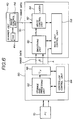
- FIG. 6 is a block diagram of the controller 60 and the main unit control unit 58 for explaining the stream of the image data.
- the image data supplied from the personal computer 70 to the controller 60 is transferred to a storage and processing unit 62.
- the storage and processing unit 62 stores the supplied image data in a memory unit such as a hard disc.
- the storage and processing unit 62 then develops the image data to the bit-map image data, and temporarily stores the bit-map image data in a memory such as a DRAM.
- a color correction process and a gradation control process are also applied to the image data. Additionally, as described later, a flag is attached to the bit-map image data, which flag indicates whether the image data corresponds to a character image or a picture image.
- the bit-map image data is then supplied to a smoothing unit 80 provided in the main unit 50 via an interface unit 66.
- the image data is subjected to a smoothing process by the smoothing unit 80, and the smoothed image data is transferred to a write control process unit 82.
- the write control process unit 82 controls a semiconductor laser 84 to scan a laser beam on the photoconductive drum 53 in synchronization with operations of other units in the main unit 50.
- the controller 60 also supplies a control signal A and a control signal B.
- the control signal A is supplied to the main unit control unit 58 so as to provide information regarding the status of the controller 60 to the main unit 50.
- the control signal A is also used to provide information regarding the image size to be output, the color of the image and a recording paper to be used.
- the control signal B is used to control the smoothing unit 80 as described later. Since the control signal B is supplied from the controller 60 to the smoothing unit 80 via an independent line, the control signal B is suitable for controlling an operation of the smoothing unit 80 which operation requires a quick response.
- the smoothing unit 80 is provided in the main unit 50 as shown in FIG. 6, the smoothing unit 80 may be provided in the controller 60 as shown in FIG. 7. That is, the smoothing unit 80 may be provided in any location between the storage and processing unit 62 of the controller 60 and the write control unit 82 of the main unit 50.
- the image data output from the scanner unit 40 is directly supplied to the write control unit 82.
- the write control unit 82 has a data selector to select one of the image data from the controller 60 and the image data from the scanner unit 40.
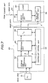
- FIG. 8 is a block diagram of a smoothing unit 80A provided in the image processing apparatus according to the first embodiment of the present invention.
- FIG. 9 is a block diagram of a smoothing unit 80B provided in the image processing apparatus according to the second embodiment of the present invention.
- the smoothing unit 8A shown in FIG. 8 has basically the same structure as the smoothing unit 8B shown in FIG. 9.
- Each of the smoothing unit 80A shown in FIG. 8 and the smoothing unit 80B shown in FIG. 9 comprises a binary process unit 1, a line buffer 2, a template matching process unit 3, a smoothing process unit 4, a data selector 5 and a register 6.
- the register 6 can store first smoothing prohibition data indicating whether or not a smoothing process is permitted to be applied to the image data on an individual image basis.
- the first smoothing prohibition data is set in the register 6 by the control signal A supplied from the controller 60.
- the first smoothing prohibition data indicates "ON”.
- the first smoothing prohibition data indicates "OFF”.
- a first control signal 10a representing the ON/OFF state of the first smoothing prohibition data is supplied to the data selector 5.
- the register 6 can also store second smoothing prohibition data indicating whether or not a smoothing process is permitted to be applied to the image data on an individual pixel basis.
- the second smoothing prohibition data is set in the register 6 by the control signal B supplied from the controller 60.
- the second smoothing prohibition data indicates "ON”.
- the second smoothing prohibition data indicates "OFF”.
- a second control signal 10b representing the ON/OFF state of the second smoothing prohibition data is supplied to the data selector 5.
- the data selector 5 selects unsmoothed image data. Otherwise, the data selector 5 selects smoothed image data output from the smoothing process unit 4.
- the second smoothing prohibition data is not set in the register 6 but is supplied from the controller 60 shown in FIG. 6. That is, the control signal B directly supplied to the smoothing unit 80B indicates the ON/OFF status of the second smoothing prohibition data.
- the data selector 5 selects one of the smoothed image data and the unsmoothed image data in accordance with the first and second smoothing prohibition data.
- the smoothing unit 80A shown in FIG. 8 is effective for a case in which the switching operation of the data selector 5 can be at a relatively low speed. That is, the smoothing unit 80A is appropriate for the slow switching between the smoothed image data and the unsmoothed image data. This is because the first and second smoothing prohibition data are supplied through an address/data line connected to the register 6.
- the smoothing unit 80B shown in FIG. 9 has an advantage that the switching between the smoothed image data and the unsmoothed image data can be made on an individual dot (pixel) basis.
- the smoothing unit 80B requires an exclusive ON/OFF switching signal line for sending the control signal B representing the ON/OFF status of the second smoothing prohibition data.
- an inexpensive controller which does not have means for setting the second smoothing prohibition data can be used by originally setting the first smoothing prohibition data to the register 6 to be "ON” and the second smoothing prohibition data to be "OFF".
- each of the threshold value data 1a of the binary process unit 1, the template data 3a of the template matching process unit 3 and the smoothing data 4a of the smoothing process unit 4 may not be set to a constant value, and may be represented by rewritable table information.
- the second smoothing prohibition data is set in the register 6.
- the register 6 of the smoothing unit shown in FIG. 8 corresponds to means for setting both the first and second smoothing prohibition data.
- a color image comprises four color planes such as Yellow, Magenta, Cyan and Black.
- the multiple value smoothing process for multiple value image data can be applied to each of the four colors. Since the object of the smoothing process (a jaggy portion correcting process) to be applied is mainly image data having a high intensity, the multiple value image data 7 (for example, represented by 8 bits) is binarized by the binary process unit 1 so as to extract a character image and a line or frame image from the multiple value image data 7. At this time, the multiple value image data 7 is compared with the threshold value data 1a in the binary process unit 1, and the pixel data having a value greater than the threshold value is extracted.
- the binarized image data is temporarily stored in the line buffer 2. Then, it is determined by the template matching process unit 3 whether or not n ⁇ m matrix pixels including and surrounding the pixel to be processed is to be subjected to the smoothing process. The result 9 of the determination made by the template matching process unit 3 is supplied to the smoothing process unit 4 and the data selector 5. Thus, the smoothing process unit 4 replaces the pixel data to be smoothed by interpolated and corrected multiple value data 8 in accordance with the smoothing data 4a, and supplies the interpolated and corrected multiple value data 8 to the data selector 5.
- the data selector 5 is provided with the interpolated and corrected multiple value data 8 and the original multiple value image data 7.
- the data selector 5 selects and outputs one of the interpolated and corrected multiple value data 8 and the original multiple value image data 7. That is, the data selector 5 selects and outputs the interpolated and corrected multiple value data 8 when both the first and second control signals 10a and 10b represent that the smoothing is not prohibited (ON state) and when the pixel to be processed is determined to be subjected to the smoothing process.
- the data selector 5 selects and outputs the original multiple value image data 7.
- a further smoothed image can be obtained by changing the level of extraction of the pixel data to be smoothed according to the ⁇ -characteristic of the print engine or some kinds of multiple value image data.
- a monochrome printer such as a facsimile machine
- an improved output image can be obtained by setting the level of extraction of the character area by changing the threshold value data 1a.
- the object to be smoothed is a character image, and there are many cases in which it is undesirable to apply the smoothing process to other image areas. Additionally, there are many cases in which the color of the character image is black. Accordingly, the deterioration in the image quality due to the smoothing error with respect to the color image data can be reduced by selecting the smoothed data when the black image data is supplied and selecting the original image data (unsmoothed data) when image data of other colors is supplied. Such an operation can be achieved by effecting the smoothing operation of the process unit 4 and selectively outputting the smoothed data by the data selector 5.
- a gradation control process such as the Dither process or the area gradation process is applied to the multiple value image data such as photographic image data.
- an optimum extraction of the pixel data to be smoothed can be achieved with respect to the data subjected to the gradation process by changing the template data 3a in the template matching process unit 3 from the data for a normal image data to the data for the image data subjected to the Dither process or the area gradation process.
- the gradation process is changed for each color.
- data optimized for each color can be used as the template data 3a.
- a further smoothed character image can be achieved by optimizing the smoothing data 4a together with the template data 3a.
- ON/OFF of the smoothing operation can be switched for each color by supplying a color signal to the register 6.
- ON/OFF of the smoothing operation can be switched at a frequency greater than that of the color change.
- the second control signal 10b (second setting means) representing the ON/OFF status of the second smoothing prohibition data is supplied separately from the first control signal 10a (first setting means) representing the ON/OFF status of the first smoothing prohibition data so that the second control signal 10b can be supplied to the data selector 5 at an image data rate (individual pixel rate). Accordingly, even when the black image data is supplied, the first control signal 10a can be set ON (smoothing process is permitted) with respect to the character image area and the second control signal 10b can be set OFF (smoothing process is prohibited).
- the second control signal 10b is supplied from the controller 60.
- the second smoothing prohibition data may be set in the register 6 as shown in FIG. 8 and an AND gate 23 may be provided as shown in FIG. 10 so as to perform an AND operation with respect to the second control signal 10b and a setting signal supplied from the controller 60 so that the smoothing process based on an individual pixel basis can be prohibited by effecting the second control signal 10b output from the register 6 only when the setting signal is supplied from the controller 60.
- the first control signal 10a may be supplied from an external unit such as the controller 60.
- the smoothing data 4a is supplied as table information which can instruct the change in the image data for each color.
- the table information can be provided for each of the colors Y, M, C and K so as to change the table information by the color signal.
- the size of the table becomes large, but there is no need to change the table information during a short period to change colors. Accordingly, the change of the tale information does not affect the image forming speed.
- the advantage of the change of the table information for each color can be achieved for other table information. It should be noted that the waiting time related to the change of the table information can be substantially eliminated if the change of the table information is performed during a startup period after the main power of the image forming apparatus is turned on.
- the smoothed image data output from the smoothing process unit 4 is directly supplied to the data selector 5.
- a ⁇ -conversion unit 22 storing a ⁇ -conversion table can be provided between the smoothing process unit 4 and the data selector 5 so as to correct the image data to match the ⁇ -characteristic of the print engine.
- the ⁇ -conversion table may be rewritable by the register 6 in accordance with the color of the image and the characteristic of the image data so that an accuracy of the correction applied to the image data can be further improved.
- threshold value data 1a, the template data 3a and the smoothing data 4a are stored in the binary process unit 1, the template matching process unit 3 and the smoothing process unit 4 respectively, the threshold value data 1a, the template data 3a and the smoothing data 4a may be stored in the register 6 so that the binary process unit 1, the template matching process unit 3 and the smoothing process unit 4 can refer to the data stored in the register 6 when it is needed.
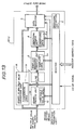
- FIG. 12 is a block diagram of a smoothing unit 80C provided in an image forming apparatus according to the third embodiment of the present invention.
- FIG. 12 parts that are the same as the parts shown in FIG. 8 are given the same reference numerals, and descriptions thereof will be omitted.
- the smoothing unit 80C does not process the multiple value image data but processes the binary image data. Accordingly, the smoothing unit 80C does not have the binary process unit 1 shown in FIG. 8, which converts multiple value image data into binary image data. Instead, the smoothing unit 80C has a binary to multiple value conversion unit 11 which converts binary image data into multiple value image data.
- the binary to multiple value conversion unit 11 produces multiple value image data which matches the characteristic of the print engine which can output an image having multiple value gradation.
- the binary to multiple value conversion unit 11 converts the binary image data into the multiple value image data by interpolation.
- the image data converted by the binary to multiple value conversion unit 11 comprises single-bit data which takes either a value "0" or "1". If the binary image data is processed by a print engine which can output 8-bit image data (up to 256 gradation levels per single dot), the binary image data must be converted into 8-bit data having gradation levels from "00" to "FF". In order to do this, the value "1" of the binary image data is converted into "FF" or "F0" of the 8-bit data in accordance with the output intensity of the print engine or user's preference. Such a binary to multiple value conversion is performed in accordance with conversion data 11a stored in the binary to multiple value conversion unit 11.
- the binary to multiple value conversion can be achieved by a conventional technique such as disclosed in Japanese Laid-Open Patent Application No. 8-223229, and detailed description thereof will be omitted. Additionally, if the binary image data is color image data, the smoothing process is performed for each color.
- the binary image data is supplied to both the binary to multiple value conversion unit 11 and the line buffer 2.
- the binary image data supplied to the line buffer 2 is processed in the same manner as that of the smoothing unit 80B shown in FIG. 9, and the smoothed data is supplied to the data selector 5.
- the binary image data supplied to the binary to multiple value conversion unit 11 is converted into the multiple value image data as mentioned above, and the multiple value image data is supplied to the data selector 5. Since the smoothed data output from the smoothing process unit 4 is multiple value image data and the image data output from the binary to multiple value conversion unit 11 is also multiple value image data, the image data selected and output from the data selector can always be multiple value image data.
- the smoothing unit 80C has the first setting means and second setting means similar to the smoothing unit 80B shown in FIG. 9. That is, the first control signal 10a is supplied to the data selector 5 from the register 6, and the second control signal 10b is supplied from an external signal source (controller 60) to the data selector 5. Accordingly, the smoothing unit 80C can provide the same advantages as the smoothing unit 80B shown in FIG. 9 with respect to the permission or prohibition of the smoothing process provided by the first and second control signals.
- the smoothing unit 80C can also perform the smoothing process for each color since the color signal is supplied thereto.
- the ⁇ -conversion unit 22 may be provided between the smoothing process unit 4 and the data selector 5 as shown in FIG. 11.
- the conversion data 11a may be stored in the register 6 instead of the binary to multiple value conversion unit 11 so that the binary to multiple value conversion unit 11 can refer to the conversion table 11a in the register 6 when it is needed.
- the second control signal 10b is supplied from the external unit (controller 60), the second control signal 10b may be supplied from the register 6 as is in the same manner as the smoothing unit 80A shown in FIG. 8.
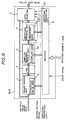
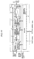
- FIG. 13 is a block diagram of a smoothing unit 80D provided in an image forming apparatus according to the fourth embodiment of the present invention.
- parts that are the same as the parts shown in FIG. 9 are given the same reference numerals, and descriptions thereof will be omitted.
- the smoothing unit 80D of the image forming apparatus is configured to process the image data including both the binary image data and the multiple value image data. As shown in FIG. 13, the smoothing unit 80D includes both a binary process unit 1A and a binary to multiple value conversion unit 11A.
- the binary process unit 1A converts the multiple value image data into binary image data, and supplies the binary image data to the line buffer 2.
- the binary process unit 1A passes through the binary image data to the line buffer 2.
- the binary to multiple value conversion unit 11A passes through the multiple value image data to the data selector 5.
- the binary to multiple value conversion unit 11A converts the binary image data into multiple value image data, and supplies the multiple value image data to the data selector 5.
- smoothing unit 80D Other structures and operations of the smoothing unit 80D are the same as that of the smoothing unit 80B shown In FIG. 9. Thus, the effects and advantages of the smoothing unit 80B can also be achieved by the smoothing unit 80D.
- the smoothing unit 80C has the first setting means and second setting means similar to the smoothing unit 80B shown in FIG. 9.
- the first control signal 10a is supplied to the data selector 5 from the register 6, and the second control signal 10b is supplied from an external signal source (controller 60) to the data selector 5.
- the smoothing unit 80D can provide the same advantages as the smoothing unit 80B shown in FIG. 9 with respect to the permission or prohibition of the smoothing process provided by the first and second control signals 10a and 10b.
- the smoothing unit 80D can also perform the smoothing process for each color since the color signal is supplied thereto.
- the ⁇ -conversion unit 22 may be provided between the smoothing process unit 4 and the data selector 5 as shown in FIG. 11.
- the conversion data 11a may be stored in the register 6 instead of the binary to multiple value conversion unit 11A so that the binary to multiple value conversion unit 11A can refer to the conversion table 11a in the register 6 when it is needed.
- the second control signal 10b is supplied from the external unit (controller 60), the second control signal 10b may be supplied from the register 6 as is in the same manner as the smoothing unit 80A shown in FIG. 8.
Abstract
Description
- The present invention generally relates to image forming apparatuses and, more particularly, to an image forming apparatus, such as a printer, a digital copy machine, a facsimile machine, an optical filing machine or an electronic sorting apparatus, which has a multiple value print engine performing a smoothing operation for removing jaggy portions of an image.
- Conventionally, there is known an image output device of a digital copy machine provided with a facsimile function. Such an image output device has a multiple value print engine and a frame memory having a multiple value structure so that an image can be represented according to 1 bit/dot, 2 bits/dot or 8 bits/dot by selecting options.
- FIG. 1 is a block diagram of a conventional binary image smoothing process circuit. In FIG. 1, the binary image smoothing process circuit comprises a
line buffer 100, a templatematching process unit 200, asmoothing process unit 300 and a dividing-smoothing process unit 400. Theline buffer 100 is a memory for storing binary image data corresponding to a plurality of lines. Theline buffer 100 supplies image data, which corresponds to n (dots) × m (lines) matrix pixel data having a center pixel to be processed, to the templatematching process unit 200. The templatematching process unit 200 compares the n × m matrix pixel data with previously stored template data for smoothing. The result of the comparison is supplied to thesmoothing process unit 300. Thesmoothing process unit 300 transforms the center pixel of the matrix pixel data, which matches the template data for smoothing, to enlarged smoothing pixels consisting of j (dots) × k (dots). The dividing-smoothing process unit 400 applies a dividing-smoothing process to the j × k enlarged smoothing pixels based on a predetermined enlarging ratio so as to convert the j × k enlarged smoothing pixels into the smoothing-processed multiple value data. - Regarding the input binary image data corresponding to a picture or a photograph, which requires gradation representation, the image data is normally supplied to a pint engine after a gradation process such as a Dither process or an error diffusion process is applied. On the other hand, the image data corresponding to characters is supplied to the print engine without being subjected to the gradation process since the character image requires sharpness to increase the character recognition rate. The above-mentioned processes are applied to the image data when the image data is subjected to the raster image development in the controller.
- The smoothing process circuit shown in FIG. 1 is used to apply the multiple value smoothing process to the binary image data. FIG. 2 is a block diagram of a smoothing process circuit, which processes multiple value image data. The smoothing process circuit shown in FIG. 2 is provided with a
line buffer 101 instead of theline buffer 100 shown in FIG. 1. Theline buffer 101 stores multiple value image data corresponding to a plurality of lines. Additionally, the smoothing process circuit shown in FIG. 2 is provided with a multiple valuesmoothing process unit 201, which processes the multiple value image data supplied from theline buffer 101. The multiple value image data is processed by thesmoothing process unit 300 and the dividing-smoothing process unit 400 in the same manner as that of the smoothing process circuit shown in FIG. 1. - However, in the above-mentioned structure of the multiple value smoothing circuit, the capacity of the
line buffer 101 and the templatematching process unit 201 must be increased due to the number of bits representing the multiple values. In order to reduce the capacity of the line buffer and the template matching process unit, there is suggested a multiple value smoothing process circuit shown in FIG. 3. - FIG. 3 is a block diagram of the multiple value
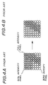
smoothing process circuit 600. The multiple valuesmoothing process circuit 600 has the same structure as the smoothing process circuit shown in FIG. 1 except for adetermination block 110 and theselector 500 being added thereto. Thedetermination block 110 is provided before theline buffer 100 so as to determine whether the input multiple value image data is a full intensity pixel. Theselector 500 is provided after the dividing-smoothing process unit 400 so as to select one of the input image data and the smoothed data output from the dividing-smoothing process unit 400. - More specifically, when the multiple value image data shown in FIG. 4A including full intensity pixels, 50% intensity pixels and zero intensity pixels is supplied to the multiple value
smoothing process circuit 600, thedetermination block 110 supplies the image data to theline buffer 100 by adding a true value = 1 only to each of the full intensity pixels. The templatematching process unit 200 applies the template matching process only to the full intensity pixels provided with the true value = 1. The thus-processed pixels are subjected to a multiple value smoothing process for binary image by thesmoothing process unit 300 and the dividing-smoothing process unit 400. Theselector 500 selects and outputs only the thus-processed pixels. Other pixels including the 50% intensity pixels and the zero intensity pixels that are not rendered to be the true value = 1 by thedetermination block 110 are selected by theselector 500, and are output without being subjected to the smoothing process. - The above-mentioned smoothing processes are disclosed in Japanese Laid-Open Patent Applications No. 9-130628 and No. 9-102870.
- The multiple value image data may include a character image or a frame image having jaggy portions. Accordingly, if the multiple value smoothing process is applied only to the binary image data, the multiple value image data is not subjected to the smoothing process. As a result, there still be a problem in that the jaggy portions remain in the character image or the frame image represented by the multiple value image data.
- On the other hand, many multiple value color images include a halftone image part such as a photographic image and a character image part. Thus, if the same smoothing process is applied to the image data corresponding to an entire sheet or page, the smoothing process to be applied to the character image is also applied to the halftone image. That is, if the halftone image part contains a pixel arrangement which matches the template data, the pixel in the pixel arrangement is subjected to the smoothing process to be applied to the character image. This results in deterioration in the degradation of the halftone image part. Additionally, a false contour which does not exist in the original image may be created in the output image. Further, there is a case in which a smoothing operation is preferably applied only to the black character image or a case in which the intensity of the smoothing process is preferably changed according to a color of the image to be processed.
- It is a general object of the present invention to provide an improved and useful image forming apparatus in which the above-mentioned problems are eliminated.
- A more specific object of the present invention is to provide an image forming apparatus which can prevent a gradation in the image represented by multiple value image data from being deteriorated due to an unnecessary smoothing process being applied to a halftone image included in the image.
- In order to achieve the above-mentioned objects, there is provided according to the present invention an image forming apparatus comprising: a print engine forming a visible image from image data supplied thereto; a controller receiving original image data from an external image data source and supplying the image data to the print engine; and a smoothing unit provided between the controller and the print engine. The smoothing unit comprises: a template matching process unit which determines whether or not the original image data is to be subjected to the smoothing process by comparing the original image data with template data, and outputs the original image data together with a selection signal indicative of a result of the determination of the template matching process unit; a smoothing process unit which selectively applies a smoothing process to the original image data based on the determination of the template matching process unit so as to output smoothed image data; a first control signal source outputting a first control signal representing whether or not application of the smoothing process is permitted on an individual image basis; a second control signal source outputting a second control signal representing whether or not application of the smoothing process is permitted on an individual pixel basis; and a selector selecting one of the original image data and the smoothed image data base on the selection signal, the first control signal and the second control signal supplied thereto.
- According to the above-mentioned invention, the original image data and the smoothed image data can be selectively output from the smoothing unit to the print engine on an individual image basis such as a character image, a picture image or a photographic image in accordance with the first control signal representing whether or not application of the smoothing process is permitted on an individual image basis. Additionally, the second control signal can prohibit the selection of the smoothed image data on an individual pixel basis even if the smoothed image data is selected by the first control signal. Accordingly, if a character image containing a picture image is supplied and the smoothed Image data is selected for the character image, the original image corresponding to the character image which is not smoothed can be selected by the second control signal. Thus, the picture image can be prevented from being deteriorated due to an unnecessary smoothing process being applied to the picture image which generates gradation errors.
- In the image forming apparatus according to the present invention, the smoothing unit may include a register for storing the register address and data so that the first and second control signal sources are provided in the register. In this case, there is no need to provide a separate signal line for the first and second control signal.
- Alternatively, in the image forming apparatus according to the present invention, the smoothing unit may include a register which provides the first control signal source, and the second control signal source may be provided in the controller so as to directly supply the second control signal to the selector without routing the register. Since the second control signal is changed on an individual pixel basis, a high-speed change can be achieved by directly supplying the second control signal to the selector from an external unit via an independent signal line.
- Additionally, when the original image data is multiple image data, the smoothing unit may include a binary process unit which converts the multiple value image data to binary image data so that the smoothing process is applied to the binary image data. On the other hand, when the original image data is binary image data, the smoothing unit may include a binary to multiple value conversion unit which converts the binary image data to multiple value image data.
- Additionally, in the present invention, when the original image data is color image data, the smoothing process may be applied to the original image data on an individual color basis.
- Other objects, features and advantages of the present invention will become more apparent from the following detailed description when read in conjunction with the accompanying drawings.
-
- FIG. 1 is a block diagram of a conventional binary image smoothing process circuit, which processes binary image data;
- FIG. 2 is a block diagram of a conventional multiple value image smoothing process circuit, which processes multiple value image data;
- FIG. 3 is a block diagram of another conventional multiple value image smoothing process circuit;
- FIG. 4A is an illustration of pixels contained in multiple value image data; FIG.4B is an illustration of pixels processed by a determination block shown in FIG. 3;
- FIG. 5 is an illustration of the entire structure of a digital copy machine to which the present invention is applied;
- FIG. 6 is a block diagram of a controller and a main unit shown in FIG. 5;
- FIG. 7 is a block diagram of a variation of the controller and the main unit show in FIG. 5;
- FIG. 8 is a block diagram of a smoothing unit provided in an image forming apparatus according to a first embodiment of the present invention;
- FIG. 9 is a block diagram of a smoothing unit provided in an image forming apparatus according to a second embodiment of the present invention;
- FIG. 10 is a block diagram of a smoothing unit, which is a variation of the smoothing unit shown in FIG. 8;
- FIG. 11 is a block diagram of a smoothing unit, which is a variation of the smoothing unit shown in FIG. 9;
- FIG. 12 is a block diagram of a smoothing unit provided in an image forming apparatus according to a third embodiment of the present invention; and
- FIG. 13 is a block diagram of a smoothing unit provided in an image forming apparatus according to a fourth embodiment of the present invention.
-
- A description will now be given of an image forming apparatus to which the present invention is applicable.
- FIG. 5 is an illustration of the entire structure of a digital copy machine to which the present invention is applied. As shown in FIG. 5, the digital copy machine comprises a
scanner unit 40, amain unit 50 and acontroller 60. Thescanner unit 40 is attached to a top of themain unit 50 so as to supply image data obtained by scanning to themain unit 50. Thecontroller 60 is connected to themain unit 50 so as to receive image data together with command data supplied from an external apparatus such as apersonal computer 70. The image data and the command data are processed by thecontroller 60, and are supplied to the processed image data to themain unit 50. - The
scanner unit 40 optically scans an original document placed on a contact glass by ascanner 42. The optical signal generated by thescanner 42 is read by aCCD unit 44. The analog image data generated by theCCD unit 44 is converted into digital image data by animage processing circuit 46. Theimage processing circuit 46 also applies a color control process and a gradation control process to the digital image data. Then, the digital image data is supplied from thescanner unit 40 to themain unit 50. - The
main unit 50 comprises apolygon mirror 51, anelectric charge unit 52, aphotoconductive drum unit 53, adevelopment unit 54, anintermediate transfer unit 55, a fixingunit 56, apaper feed unit 57 and a mainunit control unit 58. The digital image data output from themain unit 40 is supplied to awrite control unit 82 first, and, then, the digital image data is supplied to thepolygon mirror 51. The operation of each unit in themain unit 50 is known in the art, and descriptions thereof will be omitted. It should be noted that the operation of each unit in themain unit 50 is controlled by the mainunit control unit 58. The above-mentionedmain unit 50 of the digital copy machine which performs a printing operation is generally referred to as a print engine. - The digital copy machine can also output a visible image from image data supplied by the
personal computer 70. The image data supplied by thepersonal computer 70 is received by thecontroller 60. Since the image data supplied by thepersonal computer 70 may output image data having various data formats, thecontroller 60 interprets the data format of the image data supplied by thepersonal computer 70 so as to apply an appropriate color correction and gradation control process that match the characteristic of the print engine of the digital copy machine. Thecontroller 60 develops the processed image data to a bit-map image data, and transfers the bit-map image data to the mainunit control unit 58 of themain unit 50. - FIG. 6 is a block diagram of the
controller 60 and the mainunit control unit 58 for explaining the stream of the image data. The image data supplied from thepersonal computer 70 to thecontroller 60 is transferred to a storage andprocessing unit 62. The storage andprocessing unit 62 stores the supplied image data in a memory unit such as a hard disc. The storage andprocessing unit 62 then develops the image data to the bit-map image data, and temporarily stores the bit-map image data in a memory such as a DRAM. When the image data is developed to the bit-map image data, a color correction process and a gradation control process are also applied to the image data. Additionally, as described later, a flag is attached to the bit-map image data, which flag indicates whether the image data corresponds to a character image or a picture image. - The bit-map image data is then supplied to a smoothing
unit 80 provided in themain unit 50 via aninterface unit 66. The image data is subjected to a smoothing process by the smoothingunit 80, and the smoothed image data is transferred to a writecontrol process unit 82. The writecontrol process unit 82 controls asemiconductor laser 84 to scan a laser beam on thephotoconductive drum 53 in synchronization with operations of other units in themain unit 50. When the image data is supplied to the smoothingunit 80, thecontroller 60 also supplies a control signal A and a control signal B. - The control signal A is supplied to the main
unit control unit 58 so as to provide information regarding the status of thecontroller 60 to themain unit 50. The control signal A is also used to provide information regarding the image size to be output, the color of the image and a recording paper to be used. The control signal B is used to control the smoothingunit 80 as described later. Since the control signal B is supplied from thecontroller 60 to the smoothingunit 80 via an independent line, the control signal B is suitable for controlling an operation of the smoothingunit 80 which operation requires a quick response. - Although the smoothing
unit 80 is provided in themain unit 50 as shown in FIG. 6, the smoothingunit 80 may be provided in thecontroller 60 as shown in FIG. 7. That is, the smoothingunit 80 may be provided in any location between the storage andprocessing unit 62 of thecontroller 60 and thewrite control unit 82 of themain unit 50. - It should be noted that the image data output from the
scanner unit 40 is directly supplied to thewrite control unit 82. Thewrite control unit 82 has a data selector to select one of the image data from thecontroller 60 and the image data from thescanner unit 40. - A description will now be given, with reference to FIGS. 8 and 9, of an image forming apparatuses according to first embodiment and second embodiments of the present invention. FIG. 8 is a block diagram of a
smoothing unit 80A provided in the image processing apparatus according to the first embodiment of the present invention. FIG. 9 is a block diagram of asmoothing unit 80B provided in the image processing apparatus according to the second embodiment of the present invention. The smoothing unit 8A shown in FIG. 8 has basically the same structure as the smoothing unit 8B shown in FIG. 9. - Each of the smoothing
unit 80A shown in FIG. 8 and the smoothingunit 80B shown in FIG. 9 comprises a binary process unit 1, aline buffer 2, a templatematching process unit 3, asmoothing process unit 4, adata selector 5 and aregister 6. - In the
smoothing unit 80A shown in FIG. 8, theregister 6 can store first smoothing prohibition data indicating whether or not a smoothing process is permitted to be applied to the image data on an individual image basis. The first smoothing prohibition data is set in theregister 6 by the control signal A supplied from thecontroller 60. When the smoothing process is permitted on an individual image basis, the first smoothing prohibition data indicates "ON". When the smoothing process is not permitted on an individual image basis, the first smoothing prohibition data indicates "OFF". Afirst control signal 10a representing the ON/OFF state of the first smoothing prohibition data is supplied to thedata selector 5. - The
register 6 can also store second smoothing prohibition data indicating whether or not a smoothing process is permitted to be applied to the image data on an individual pixel basis. The second smoothing prohibition data is set in theregister 6 by the control signal B supplied from thecontroller 60. When the smoothing process is permitted on an individual pixel basis, the second smoothing prohibition data indicates "ON". When the smoothing process is not permitted on an individual pixel basis, the second smoothing prohibition data indicates "OFF". A second control signal 10b representing the ON/OFF state of the second smoothing prohibition data is supplied to thedata selector 5. - When both the first smoothing prohibition data and the second smoothing prohibition data in the register indicate "OFF", the
data selector 5 selects unsmoothed image data. Otherwise, thedata selector 5 selects smoothed image data output from thesmoothing process unit 4. - In the
smoothing unit 80B shown in FIG.9, the second smoothing prohibition data is not set in theregister 6 but is supplied from thecontroller 60 shown in FIG. 6. That is, the control signal B directly supplied to thesmoothing unit 80B indicates the ON/OFF status of the second smoothing prohibition data. Thedata selector 5 selects one of the smoothed image data and the unsmoothed image data in accordance with the first and second smoothing prohibition data. - The smoothing
unit 80A shown in FIG. 8 is effective for a case in which the switching operation of thedata selector 5 can be at a relatively low speed. That is, the smoothingunit 80A is appropriate for the slow switching between the smoothed image data and the unsmoothed image data. This is because the first and second smoothing prohibition data are supplied through an address/data line connected to theregister 6. - On the other hand, the smoothing
unit 80B shown in FIG. 9 has an advantage that the switching between the smoothed image data and the unsmoothed image data can be made on an individual dot (pixel) basis. However, the smoothingunit 80B requires an exclusive ON/OFF switching signal line for sending the control signal B representing the ON/OFF status of the second smoothing prohibition data. - In the smoothing
units register 6 to be "ON" and the second smoothing prohibition data to be "OFF". Additionally, each of the threshold value data 1a of the binary process unit 1, thetemplate data 3a of the templatematching process unit 3 and the smoothing data 4a of thesmoothing process unit 4 may not be set to a constant value, and may be represented by rewritable table information. - It should be noted that, in FIG. 8, the second smoothing prohibition data is set in the
register 6. Thus, theregister 6 of the smoothing unit shown in FIG. 8 corresponds to means for setting both the first and second smoothing prohibition data. - A description will now be given of an operation of the smoothing
units - Normally, a color image comprises four color planes such as Yellow, Magenta, Cyan and Black. Thus, the multiple value smoothing process for multiple value image data can be applied to each of the four colors. Since the object of the smoothing process (a jaggy portion correcting process) to be applied is mainly image data having a high intensity, the multiple value image data 7 (for example, represented by 8 bits) is binarized by the binary process unit 1 so as to extract a character image and a line or frame image from the multiple
value image data 7. At this time, the multiplevalue image data 7 is compared with the threshold value data 1a in the binary process unit 1, and the pixel data having a value greater than the threshold value is extracted. - The binarized image data is temporarily stored in the
line buffer 2. Then, it is determined by the templatematching process unit 3 whether or not n × m matrix pixels including and surrounding the pixel to be processed is to be subjected to the smoothing process. Theresult 9 of the determination made by the templatematching process unit 3 is supplied to thesmoothing process unit 4 and thedata selector 5. Thus, thesmoothing process unit 4 replaces the pixel data to be smoothed by interpolated and correctedmultiple value data 8 in accordance with the smoothing data 4a, and supplies the interpolated and correctedmultiple value data 8 to thedata selector 5. - The
data selector 5 is provided with the interpolated and correctedmultiple value data 8 and the original multiplevalue image data 7. Thedata selector 5 selects and outputs one of the interpolated and correctedmultiple value data 8 and the original multiplevalue image data 7. That is, thedata selector 5 selects and outputs the interpolated and correctedmultiple value data 8 when both the first andsecond control signals 10a and 10b represent that the smoothing is not prohibited (ON state) and when the pixel to be processed is determined to be subjected to the smoothing process. On the other hand, when it is determined by the templatematching process unit 3 that the pixel data to be processed does not correspond to the pixel data to be smoothed, thedata selector 5 selects and outputs the original multiplevalue image data 7. - It should be noted that there is a case in which a further smoothed image can be obtained by changing the level of extraction of the pixel data to be smoothed according to the γ-characteristic of the print engine or some kinds of multiple value image data. For example, when a monochrome printer such as a facsimile machine is used, an improved output image (character image) can be obtained by setting the level of extraction of the character area by changing the threshold value data 1a.
- In the case of a color image data, undesired color changes can be reduced by reducing errors caused by a smoothing process. This can be achieved by lowering the threshold value data 1a with respect to black image data so as to more easily extract the black character image, and setting the threshold value data to a higher value (for example, FF(H) for 8-bits multiple value image) with respect to other colors.
- Even if the threshold value data is changed for each color, errors cannot be completely eliminated. In the color image data, the object to be smoothed is a character image, and there are many cases in which it is undesirable to apply the smoothing process to other image areas. Additionally, there are many cases in which the color of the character image is black. Accordingly, the deterioration in the image quality due to the smoothing error with respect to the color image data can be reduced by selecting the smoothed data when the black image data is supplied and selecting the original image data (unsmoothed data) when image data of other colors is supplied. Such an operation can be achieved by effecting the smoothing operation of the
process unit 4 and selectively outputting the smoothed data by thedata selector 5. - Additionally, there is a case in which a gradation control process such as the Dither process or the area gradation process is applied to the multiple value image data such as photographic image data. In such a case, an optimum extraction of the pixel data to be smoothed can be achieved with respect to the data subjected to the gradation process by changing the
template data 3a in the templatematching process unit 3 from the data for a normal image data to the data for the image data subjected to the Dither process or the area gradation process. In the case of a color image, there are many cases in which the gradation process is changed for each color. Thus, data optimized for each color can be used as thetemplate data 3a. A further smoothed character image can be achieved by optimizing the smoothing data 4a together with thetemplate data 3a. - In the structure shown in FIG. 8, ON/OFF of the smoothing operation can be switched for each color by supplying a color signal to the
register 6. On the other hand, in the structure shown in FIG. 9, ON/OFF of the smoothing operation can be switched at a frequency greater than that of the color change. In thesmoothing unit 80B shown in FIG. 9, the second control signal 10b (second setting means) representing the ON/OFF status of the second smoothing prohibition data is supplied separately from thefirst control signal 10a (first setting means) representing the ON/OFF status of the first smoothing prohibition data so that the second control signal 10b can be supplied to thedata selector 5 at an image data rate (individual pixel rate). Accordingly, even when the black image data is supplied, thefirst control signal 10a can be set ON (smoothing process is permitted) with respect to the character image area and the second control signal 10b can be set OFF (smoothing process is prohibited). - It should be noted that, in FIG. 9, the second control signal 10b is supplied from the
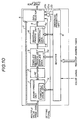
controller 60. Alternatively, the second smoothing prohibition data may be set in theregister 6 as shown in FIG. 8 and an ANDgate 23 may be provided as shown in FIG. 10 so as to perform an AND operation with respect to the second control signal 10b and a setting signal supplied from thecontroller 60 so that the smoothing process based on an individual pixel basis can be prohibited by effecting the second control signal 10b output from theregister 6 only when the setting signal is supplied from thecontroller 60. Additionally, thefirst control signal 10a may be supplied from an external unit such as thecontroller 60. - The smoothing data 4a is supplied as table information which can instruct the change in the image data for each color. In this case, although the size of the table information can be small, the table information must be changed during the changeover of colors which is not appropriate for a high-speed printer. The table information can be provided for each of the colors Y, M, C and K so as to change the table information by the color signal. In such a case, the size of the table becomes large, but there is no need to change the table information during a short period to change colors. Accordingly, the change of the tale information does not affect the image forming speed. The advantage of the change of the table information for each color can be achieved for other table information. It should be noted that the waiting time related to the change of the table information can be substantially eliminated if the change of the table information is performed during a startup period after the main power of the image forming apparatus is turned on.
- In the above-mentioned embodiments, the smoothed image data output from the
smoothing process unit 4 is directly supplied to thedata selector 5. However, as shown in FIG. 11, a γ-conversion unit 22 storing a γ-conversion table can be provided between the smoothingprocess unit 4 and thedata selector 5 so as to correct the image data to match the γ-characteristic of the print engine. The γ-conversion table may be rewritable by theregister 6 in accordance with the color of the image and the characteristic of the image data so that an accuracy of the correction applied to the image data can be further improved. - Additionally, although the threshold value data 1a, the
template data 3a and the smoothing data 4a are stored in the binary process unit 1, the templatematching process unit 3 and thesmoothing process unit 4 respectively, the threshold value data 1a, thetemplate data 3a and the smoothing data 4a may be stored in theregister 6 so that the binary process unit 1, the templatematching process unit 3 and thesmoothing process unit 4 can refer to the data stored in theregister 6 when it is needed. - A description will now be given, with reference to FIG. 12, of a third embodiment of the present invention. FIG. 12 is a block diagram of a smoothing unit 80C provided in an image forming apparatus according to the third embodiment of the present invention. In FIG. 12, parts that are the same as the parts shown in FIG. 8 are given the same reference numerals, and descriptions thereof will be omitted.
- The smoothing unit 80C does not process the multiple value image data but processes the binary image data. Accordingly, the smoothing unit 80C does not have the binary process unit 1 shown in FIG. 8, which converts multiple value image data into binary image data. Instead, the smoothing unit 80C has a binary to multiple value conversion unit 11 which converts binary image data into multiple value image data. The binary to multiple value conversion unit 11 produces multiple value image data which matches the characteristic of the print engine which can output an image having multiple value gradation. The binary to multiple value conversion unit 11 converts the binary image data into the multiple value image data by interpolation.
- The image data converted by the binary to multiple value conversion unit 11 comprises single-bit data which takes either a value "0" or "1". If the binary image data is processed by a print engine which can output 8-bit image data (up to 256 gradation levels per single dot), the binary image data must be converted into 8-bit data having gradation levels from "00" to "FF". In order to do this, the value "1" of the binary image data is converted into "FF" or "F0" of the 8-bit data in accordance with the output intensity of the print engine or user's preference. Such a binary to multiple value conversion is performed in accordance with conversion data 11a stored in the binary to multiple value conversion unit 11.
- It should be noted that the binary to multiple value conversion can be achieved by a conventional technique such as disclosed in Japanese Laid-Open Patent Application No. 8-223229, and detailed description thereof will be omitted. Additionally, if the binary image data is color image data, the smoothing process is performed for each color.
- In the smoothing unit 80C according to the third embodiment of the present invention, the binary image data is supplied to both the binary to multiple value conversion unit 11 and the
line buffer 2. The binary image data supplied to theline buffer 2 is processed in the same manner as that of the smoothingunit 80B shown in FIG. 9, and the smoothed data is supplied to thedata selector 5. On the other hand, the binary image data supplied to the binary to multiple value conversion unit 11 is converted into the multiple value image data as mentioned above, and the multiple value image data is supplied to thedata selector 5. Since the smoothed data output from thesmoothing process unit 4 is multiple value image data and the image data output from the binary to multiple value conversion unit 11 is also multiple value image data, the image data selected and output from the data selector can always be multiple value image data. - As shown in FIG. 12, the smoothing unit 80C has the first setting means and second setting means similar to the
smoothing unit 80B shown in FIG. 9. That is, thefirst control signal 10a is supplied to thedata selector 5 from theregister 6, and the second control signal 10b is supplied from an external signal source (controller 60) to thedata selector 5. Accordingly, the smoothing unit 80C can provide the same advantages as the smoothingunit 80B shown in FIG. 9 with respect to the permission or prohibition of the smoothing process provided by the first and second control signals. - Additionally, similar to the above-mentioned
smoothing units conversion unit 22 may be provided between the smoothingprocess unit 4 and thedata selector 5 as shown in FIG. 11. Additionally, the conversion data 11a may be stored in theregister 6 instead of the binary to multiple value conversion unit 11 so that the binary to multiple value conversion unit 11 can refer to the conversion table 11a in theregister 6 when it is needed. - It should be noted that although the second control signal 10b is supplied from the external unit (controller 60), the second control signal 10b may be supplied from the
register 6 as is in the same manner as the smoothingunit 80A shown in FIG. 8. - A description will now be given, with reference to FIG. 13, of a fourth embodiment of the present invention. FIG. 13 is a block diagram of a smoothing unit 80D provided in an image forming apparatus according to the fourth embodiment of the present invention. In FIG. 13, parts that are the same as the parts shown in FIG. 9 are given the same reference numerals, and descriptions thereof will be omitted.
- The smoothing unit 80D of the image forming apparatus according to the fourth embodiment of the present invention is configured to process the image data including both the binary image data and the multiple value image data. As shown in FIG. 13, the smoothing unit 80D includes both a binary process unit 1A and a binary to multiple value conversion unit 11A.
- When the original image data is multiple value image data, the binary process unit 1A converts the multiple value image data into binary image data, and supplies the binary image data to the
line buffer 2. When the original image data is binary image data, the binary process unit 1A passes through the binary image data to theline buffer 2. - On the other hand, when the original image data is multiple value image data, the binary to multiple value conversion unit 11A passes through the multiple value image data to the
data selector 5. When the original image data is binary image data, the binary to multiple value conversion unit 11A converts the binary image data into multiple value image data, and supplies the multiple value image data to thedata selector 5. - Other structures and operations of the smoothing unit 80D are the same as that of the smoothing
unit 80B shown In FIG. 9. Thus, the effects and advantages of the smoothingunit 80B can also be achieved by the smoothing unit 80D. - That is, as shown in FIG. 12, the smoothing unit 80C has the first setting means and second setting means similar to the
smoothing unit 80B shown in FIG. 9. Thefirst control signal 10a is supplied to thedata selector 5 from theregister 6, and the second control signal 10b is supplied from an external signal source (controller 60) to thedata selector 5. Accordingly, the smoothing unit 80D can provide the same advantages as the smoothingunit 80B shown in FIG. 9 with respect to the permission or prohibition of the smoothing process provided by the first andsecond control signals 10a and 10b. - Additionally, similar to the above-mentioned
smoothing units conversion unit 22 may be provided between the smoothingprocess unit 4 and thedata selector 5 as shown in FIG. 11. Additionally, the conversion data 11a may be stored in theregister 6 instead of the binary to multiple value conversion unit 11A so that the binary to multiple value conversion unit 11A can refer to the conversion table 11a in theregister 6 when it is needed. - It should be noted that although the second control signal 10b is supplied from the external unit (controller 60), the second control signal 10b may be supplied from the
register 6 as is in the same manner as the smoothingunit 80A shown in FIG. 8. - The present invention is not limited to the specifically disclosed embodiments, and variations and modifications may be made without departing from the scope of the present invention.
- The present application is based on Japanese priority applications No. 11-232812 filed August 19, 1999, No. 2000-030790 filed February 8, 2000 and No. 12-180327, the entire contents of which are hereby incorporated by reference.
Claims (26)
- An image forming apparatus comprising:a print engine (82, 84, 51-58) forming a visible image by image data supplied thereto;a controller (60) receiving original image data from an external image-data source and supplying the image data to said print engine; anda smoothing unit (80A-80D) provided between said controller and said print engine,
characterized in that said smoothing unit comprises:a template matching process unit (3) which determines whether or not the original image data is to be subjected to the smoothing process by comparing the original image data with template data, and outputs the original image data together with a selection signal (9) indicative of a result of the determination of said template matching process unit;a smoothing process unit (4) which selectively applies a smoothing process to the original image data based on the determination of said template matching process unit (3) so as to output smoothed image data;a first control signal source outputting a first control signal (10a) representing whether or not application of the smoothing process is permitted on an individual image basis;a second control signal source outputting a second control signal (10b) representing whether or not application of the smoothing process is permitted on an individual pixel basis; anda selector (5) selecting one of the original image data and the smoothed image data base on the selection signal (9), the first control signal (10a) and the second control signal (10b) supplied thereto. - The image forming apparatus as claimed in claim 1, characterized in that said smoothing unit (80A) includes a register (6) so that the first and second control signal sources are provided in said register.
- The image forming apparatus as claimed in claim 1, characterized in that said smoothing unit (80B) includes a register (6) so that the first control signal source is provided in the register (6), and the second control signal source is provided in said controller (60) so that the second control signal (10b) is directly supplied to said selector (5) without routing said register (6).
- The image forming apparatus as claimed in claim 1, characterized in that the original image data is multiple value image data, and said smoothing unit (80A, 80B) includes a binary process unit (1) which binarizes the original image data and supplies the binarized original image data to said template matching process (3).
- The image forming apparatus as claimed in claim 4, characterized in that said binary process unit (1) binarizes the original image data by comparing the original image data with threshold value data which is externally changeable.
- The image forming apparatus as claimed in claim 1, characterized in that the original data is binary image data, and said smoothing unit (80C) includes a binary to multiple value conversion unit (11) which converts the original image data into multiple value image data and supplies the multiple value original Image data to said selector (5).
- The image forming apparatus as claimed in claim 1, characterized in that the original image data includes binary image data and multiple value image data, and said smoothing unit (80D) includes a binary process unit (1A) and a binary to multiple value conversion unit (11A), said binary process unit (1A) binarizing the original image data and supplying the binarized original image data to said template matching process (3), said binary to multiple value conversion unit (11A) converting the original image data into multiple value image data and supplying the multiple value original image data to said selector (5).
- The image forming apparatus as claimed in claim 7, characterized in that said binary process unit (1A) binarizes the original image data by comparing the original image data with threshold value data which is externally changeable.
- The image forming apparatus as claimed in claim 1, characterized in that the second control signal (10b) is effected so as to prohibit the smoothing process only when the smoothing process is permitted on an individual image basis by the first control signal (10a).
- The image forming apparatus as claimed in claim 1, characterized in that the template data (3a) of said template matching process unit (3) is changeable externally.
- The image forming apparatus as claimed in claim 1, characterized in that said smoothing process unit (4) applies the smoothing process based on smoothing data (4a) which is externally changeable.
- The image forming apparatus as claimed in claim 1, characterized in that the original image data is color image data, and the first control signal (10a) represents whether or not application of the smoothing process is permitted on an individual color basis.
- The image forming apparatus as claimed in claim 12, characterized in that the second control signal (10b) is effected so as to prohibit the smoothing process only when the smoothing process is permitted on an individual color basis by the first control signal (10a).
- The image forming apparatus as claimed in claim 5, characterized in that the original image data is color image data, and the threshold value data (1a) is set on an individual color basis.
- The image forming apparatus as claimed in claim 1, characterized in that the original image data is color image data, and the template data (3a) is set on an individual color basis.
- The image forming apparatus as claimed in claim 11, characterized in that the original image data is color image data, and the smoothing data (4a) is set on an individual color basis.
- The image forming apparatus as claimed in claim 16, characterized in that the smoothing data (4a) comprises table information which is set on an individual color basis.
- The image forming apparatus as claimed in claim 1, characterized in that said smoothing unit (80A-80D) further comprises a γ-conversion unit (22) which applied a γ-conversion process to the smoothed image data output from the smoothing process unit (4), the γ-conversion process being applied in accordance with γ-conversion data.
- The image forming apparatus as claimed in claim 18, characterized in that the γ-conversion data is changeable externally.
- The image forming apparatus as claimed in claim 19, characterized in that the original image data is color image data, and the γ-conversion data is set on an individual color basis.
- The image forming apparatus as claimed in claim 1, characterized in that said smoothing unit (80A-80D) further comprises a register (6) which stores the template data (3a) used by said template matching process unit (3).
- The image forming apparatus as claimed in claim 21, characterized in that said register (6) further stores threshold value data (1a) and smoothing data (4a), the threshold value data (1a) being used to binarize the original image data by comparing the original image data with the threshold value data (1a), the smoothing data (4a) being used to apply the smoothing process to the original image data.
- The image forming apparatus as claimed in claim 22, characterized in that at least one of the first and second control signal sources is provided in said register (6).
- The image forming apparatus as claimed in claim 1, characterized in that the second control signal source outputs the second control signal (10b) based on whether or not a gradation control process is applied to the smoothed image data.
- The image forming apparatus as claimed in claim 24, characterized in that the gradation control process is one of a Dither process and a gradation area process.
- A controller (60) adapted to receive original image data from an external image-data source (70) and supply image data to a print engine (50), said controller comprising:a storage and processing unit (62) which applies a predetermined process to the original image data and outputs processed original image data; anda smoothing unit (80) which applies a smoothing process to the original image data output from said storage and processing unit (62),
characterized in that said smoothing unit (80) comprises:a template matching process unit (3) which determines whether or not the original image data output from said storage and processing unit is to be subjected to the smoothing process by comparing the original image data with template data (3a), and outputs the original image data together with a selection signal (9) indicative of a result of the determination of said template matching process unit (3);a smoothing process unit (4) which selectively applies the smoothing process to the original image data based on the determination of said template matching process unit (3) so as to output smoothed image data;a first control signal source outputting a first control signal (10a) representing whether or not application of the smoothing process is permitted on an individual image basis;a second control signal source outputting a second control signal (10b) representing whether or not application of the smoothing process is permitted on an individual pixel basis; anda selector (5) selecting one of the original image data and the smoothed image data base on the selection signal (9), the first control signal (10a) and the second control signal (10b) supplied thereto.
Applications Claiming Priority (6)
| Application Number | Priority Date | Filing Date | Title |
|---|---|---|---|
| JP23281299 | 1999-08-19 | ||
| JP23281299 | 1999-08-19 | ||
| JP2000030790 | 2000-02-08 | ||
| JP2000030790 | 2000-02-08 | ||
| JP2000180327 | 2000-06-15 | ||
| JP2000180327A JP3982979B2 (en) | 1999-08-19 | 2000-06-15 | Image forming apparatus |
Publications (3)
| Publication Number | Publication Date |
|---|---|
| EP1077572A2 true EP1077572A2 (en) | 2001-02-21 |
| EP1077572A3 EP1077572A3 (en) | 2001-04-11 |
| EP1077572B1 EP1077572B1 (en) | 2002-10-09 |
Family
ID=27331924
Family Applications (1)
| Application Number | Title | Priority Date | Filing Date |
|---|---|---|---|
| EP00117284A Expired - Lifetime EP1077572B1 (en) | 1999-08-19 | 2000-08-17 | Image forming apparatus selectively applying a smoothing operation to image data |
Country Status (6)
| Country | Link |
|---|---|
| US (1) | US7064866B1 (en) |
| EP (1) | EP1077572B1 (en) |
| JP (1) | JP3982979B2 (en) |
| AT (1) | ATE225997T1 (en) |
| DE (1) | DE60003615T2 (en) |
| ES (1) | ES2184670T3 (en) |
Families Citing this family (7)
| Publication number | Priority date | Publication date | Assignee | Title |
|---|---|---|---|---|
| WO2003096675A1 (en) * | 2002-05-14 | 2003-11-20 | Fuji Xerox Co., Ltd. | Color image creating device and color image creating method |
| JP4189169B2 (en) * | 2002-05-15 | 2008-12-03 | 富士フイルム株式会社 | Color conversion definition correcting device and color conversion definition correcting program |
| JP4181881B2 (en) * | 2003-01-22 | 2008-11-19 | キヤノン株式会社 | Image processing apparatus and method |
| JP4118886B2 (en) | 2005-01-21 | 2008-07-16 | シャープ株式会社 | Image processing apparatus, image forming apparatus, image reading processing apparatus, image processing method, image processing program, and computer-readable recording medium |
| JP4165521B2 (en) * | 2005-03-30 | 2008-10-15 | ブラザー工業株式会社 | Image processing apparatus and image forming apparatus |
| EP1777938A1 (en) * | 2005-10-19 | 2007-04-25 | Thomson Licensing | Method, system and device for colour quality control |
| JP5181956B2 (en) * | 2008-03-03 | 2013-04-10 | 株式会社リコー | Electrophotographic equipment |
Citations (3)
| Publication number | Priority date | Publication date | Assignee | Title |
|---|---|---|---|---|
| EP0768792A2 (en) * | 1995-10-11 | 1997-04-16 | Xerox Corporation | Method and apparatus for the resolution enhancement of gray scale images that include text and line art |
| EP0862319A1 (en) * | 1994-03-11 | 1998-09-02 | Hewlett-Packard Company | Pixel correction and smoothing method |
| JP2000092327A (en) * | 1998-09-08 | 2000-03-31 | Ricoh Co Ltd | Image forming device |
Family Cites Families (12)
| Publication number | Priority date | Publication date | Assignee | Title |
|---|---|---|---|---|
| JPH02178656A (en) * | 1988-12-28 | 1990-07-11 | Fuji Photo Film Co Ltd | Method and device for under-color removal |
| JPH04294466A (en) * | 1991-03-22 | 1992-10-19 | Ricoh Co Ltd | Image processor |
| KR950003035B1 (en) * | 1992-04-17 | 1995-03-29 | 주식회사 금성사 | Apparatus and method for emphasizing image transition portion |
| JPH0818777A (en) * | 1994-03-08 | 1996-01-19 | Ricoh Co Ltd | Picture processor |
| US5754708A (en) * | 1994-11-16 | 1998-05-19 | Mita Industrial Co. Ltd. | Dotted image area detecting apparatus and dotted image area detecting method |
| JPH08223229A (en) | 1995-02-17 | 1996-08-30 | Sony Corp | Baseband transmission system, transmitter and receiver |
| US5553200A (en) * | 1995-03-03 | 1996-09-03 | Electronics For Imaging, Inc. | Method and apparatus for providing bit-rate reduction and reconstruction of image data using dither arrays |
| JPH09102870A (en) | 1995-10-05 | 1997-04-15 | Fuji Xerox Co Ltd | Image processor |
| JPH09130628A (en) | 1995-10-27 | 1997-05-16 | Ricoh Co Ltd | Multi-value smoothing processing method |
| JP3581477B2 (en) * | 1996-03-04 | 2004-10-27 | 株式会社リコー | Digital copier |
| US6181438B1 (en) * | 1997-05-05 | 2001-01-30 | Xerox Corporation | Method and apparatus for digital image darkness control using quantized fractional pixels |
| US6195473B1 (en) * | 1997-12-26 | 2001-02-27 | International Business Machines Corporation | Non-integer scaling of raster images with image quality enhancement |
-
2000
- 2000-06-15 JP JP2000180327A patent/JP3982979B2/en not_active Expired - Fee Related
- 2000-08-17 DE DE60003615T patent/DE60003615T2/en not_active Expired - Lifetime
- 2000-08-17 ES ES00117284T patent/ES2184670T3/en not_active Expired - Lifetime
- 2000-08-17 EP EP00117284A patent/EP1077572B1/en not_active Expired - Lifetime
- 2000-08-17 US US09/640,068 patent/US7064866B1/en not_active Expired - Fee Related
- 2000-08-17 AT AT00117284T patent/ATE225997T1/en not_active IP Right Cessation
Patent Citations (3)
| Publication number | Priority date | Publication date | Assignee | Title |
|---|---|---|---|---|
| EP0862319A1 (en) * | 1994-03-11 | 1998-09-02 | Hewlett-Packard Company | Pixel correction and smoothing method |
| EP0768792A2 (en) * | 1995-10-11 | 1997-04-16 | Xerox Corporation | Method and apparatus for the resolution enhancement of gray scale images that include text and line art |
| JP2000092327A (en) * | 1998-09-08 | 2000-03-31 | Ricoh Co Ltd | Image forming device |
Non-Patent Citations (1)
| Title |
|---|
| PATENT ABSTRACTS OF JAPAN vol. 2000, no. 06, 22 September 2000 (2000-09-22) & JP 2000 092327 A (RICOH CO LTD), 31 March 2000 (2000-03-31) * |
Also Published As
| Publication number | Publication date |
|---|---|
| ATE225997T1 (en) | 2002-10-15 |
| JP2001298620A (en) | 2001-10-26 |
| ES2184670T3 (en) | 2003-04-16 |
| EP1077572B1 (en) | 2002-10-09 |
| US7064866B1 (en) | 2006-06-20 |
| EP1077572A3 (en) | 2001-04-11 |
| JP3982979B2 (en) | 2007-09-26 |
| DE60003615T2 (en) | 2004-09-30 |
| DE60003615D1 (en) | 2003-08-07 |
Similar Documents
| Publication | Publication Date | Title |
|---|---|---|
| US7319548B2 (en) | Image processing device having functions for detecting specified images | |
| US7684085B2 (en) | Methods and apparatus for reconstructing digitized images | |
| US7903872B2 (en) | Image-processing apparatus and method, computer program, and storage medium | |
| EP1505821B1 (en) | Image processing apparatus, an image forming apparatus and an image processing method | |
| US7064862B2 (en) | Printer and printing method for image-quality correction | |
| US20100165413A1 (en) | Image Processing Apparatus and Image Processing Method for Supressing Jaggies in the Edge Portions of Image | |
| US20070058224A1 (en) | Image processing apparatus and image processing method | |
| JPH0799570A (en) | Method and device for forming image | |
| US6824240B2 (en) | Image processing apparatus and method and recording medium | |
| US5835238A (en) | Phantom level edge enhanced error diffusion | |
| EP0998121B1 (en) | Image processing device and image processing method | |
| JPH07117284A (en) | Image processor and method thereof | |
| EP1077572B1 (en) | Image forming apparatus selectively applying a smoothing operation to image data | |
| JP2008092541A (en) | Image processing method, image processor, image forming apparatus, computer program, and recording medium | |
| JPH11177825A (en) | Image processor | |
| JPH09179973A (en) | Picture processor and its method | |
| JP2003051940A (en) | Image processing method and device thereof | |
| JPH114352A (en) | Image processing method, system and recording medium | |
| US7324230B2 (en) | Image forming apparatus and image forming method for forming color and monochromatic images | |
| JPH05191642A (en) | Picture output device | |
| JPH09179964A (en) | System and method for image input/output data processing, and input/output data controller for the same system | |
| JPH1188653A (en) | Image-processing unit, method therefor and storage medium | |
| JP2004166172A (en) | Image processor, image forming apparatus, image reader, program and storage medium | |
| JP2007282125A (en) | Image processor, multifunctional device, and image processing method | |
| JP2006270816A (en) | Image processing apparatus |
Legal Events
| Date | Code | Title | Description |
|---|---|---|---|
| PUAI | Public reference made under article 153(3) epc to a published international application that has entered the european phase |
Free format text: ORIGINAL CODE: 0009012 |
|
| 17P | Request for examination filed |
Effective date: 20000817 |
|
| AK | Designated contracting states |
Kind code of ref document: A2 Designated state(s): AT BE CH CY DE DK ES FI FR GB GR IE IT LI LU MC NL PT SE |
|
| AX | Request for extension of the european patent |
Free format text: AL;LT;LV;MK;RO;SI |
|
| PUAL | Search report despatched |
Free format text: ORIGINAL CODE: 0009013 |
|
| AK | Designated contracting states |
Kind code of ref document: A3 Designated state(s): AT BE CH CY DE DK ES FI FR GB GR IE IT LI LU MC NL PT SE |
|
| AX | Request for extension of the european patent |
Free format text: AL;LT;LV;MK;RO;SI |
|
| 17Q | First examination report despatched |
Effective date: 20010723 |
|
| AKX | Designation fees paid | ||
| RBV | Designated contracting states (corrected) |
Designated state(s): AT BE CH CY DE DK ES FI FR GB GR IE IT LI LU MC NL PT SE |
|
| GRAG | Despatch of communication of intention to grant |
Free format text: ORIGINAL CODE: EPIDOS AGRA |
|
| REG | Reference to a national code |
Ref country code: DE Ref legal event code: 8566 |
|
| GRAG | Despatch of communication of intention to grant |
Free format text: ORIGINAL CODE: EPIDOS AGRA |
|
| GRAH | Despatch of communication of intention to grant a patent |
Free format text: ORIGINAL CODE: EPIDOS IGRA |
|
| GRAH | Despatch of communication of intention to grant a patent |
Free format text: ORIGINAL CODE: EPIDOS IGRA |
|
| GRAA | (expected) grant |
Free format text: ORIGINAL CODE: 0009210 |
|
| AK | Designated contracting states |
Kind code of ref document: B1 Designated state(s): AT BE CH CY DE DK ES FI FR GB GR IE IT LI LU MC NL PT SE |
|
| PG25 | Lapsed in a contracting state [announced via postgrant information from national office to epo] |
Ref country code: LI Free format text: LAPSE BECAUSE OF FAILURE TO SUBMIT A TRANSLATION OF THE DESCRIPTION OR TO PAY THE FEE WITHIN THE PRESCRIBED TIME-LIMIT Effective date: 20021009 Ref country code: FI Free format text: LAPSE BECAUSE OF FAILURE TO SUBMIT A TRANSLATION OF THE DESCRIPTION OR TO PAY THE FEE WITHIN THE PRESCRIBED TIME-LIMIT Effective date: 20021009 Ref country code: AT Free format text: LAPSE BECAUSE OF FAILURE TO SUBMIT A TRANSLATION OF THE DESCRIPTION OR TO PAY THE FEE WITHIN THE PRESCRIBED TIME-LIMIT Effective date: 20021009 Ref country code: CH Free format text: LAPSE BECAUSE OF FAILURE TO SUBMIT A TRANSLATION OF THE DESCRIPTION OR TO PAY THE FEE WITHIN THE PRESCRIBED TIME-LIMIT Effective date: 20021009 Ref country code: GR Free format text: LAPSE BECAUSE OF FAILURE TO SUBMIT A TRANSLATION OF THE DESCRIPTION OR TO PAY THE FEE WITHIN THE PRESCRIBED TIME-LIMIT Effective date: 20021009 Ref country code: BE Free format text: LAPSE BECAUSE OF FAILURE TO SUBMIT A TRANSLATION OF THE DESCRIPTION OR TO PAY THE FEE WITHIN THE PRESCRIBED TIME-LIMIT Effective date: 20021009 |
|
| REF | Corresponds to: |
Ref document number: 225997 Country of ref document: AT Date of ref document: 20021015 Kind code of ref document: T |
|
| REG | Reference to a national code |
Ref country code: GB Ref legal event code: FG4D |
|
| REG | Reference to a national code |
Ref country code: CH Ref legal event code: EP |
|
| REG | Reference to a national code |
Ref country code: IE Ref legal event code: FG4D |
|
| PG25 | Lapsed in a contracting state [announced via postgrant information from national office to epo] |
Ref country code: SE Free format text: LAPSE BECAUSE OF FAILURE TO SUBMIT A TRANSLATION OF THE DESCRIPTION OR TO PAY THE FEE WITHIN THE PRESCRIBED TIME-LIMIT Effective date: 20030109 Ref country code: PT Free format text: LAPSE BECAUSE OF FAILURE TO SUBMIT A TRANSLATION OF THE DESCRIPTION OR TO PAY THE FEE WITHIN THE PRESCRIBED TIME-LIMIT Effective date: 20030109 Ref country code: DK Free format text: LAPSE BECAUSE OF FAILURE TO SUBMIT A TRANSLATION OF THE DESCRIPTION OR TO PAY THE FEE WITHIN THE PRESCRIBED TIME-LIMIT Effective date: 20030109 |
|
| REG | Reference to a national code |
Ref country code: CH Ref legal event code: PL |
|
| REG | Reference to a national code |
Ref country code: ES Ref legal event code: FG2A Ref document number: 2184670 Country of ref document: ES Kind code of ref document: T3 |
|
| ET | Fr: translation filed | ||
| REF | Corresponds to: |
Ref document number: 60003615 Country of ref document: DE Date of ref document: 20030807 Kind code of ref document: P |
|
| PLBE | No opposition filed within time limit |
Free format text: ORIGINAL CODE: 0009261 |
|
| STAA | Information on the status of an ep patent application or granted ep patent |
Free format text: STATUS: NO OPPOSITION FILED WITHIN TIME LIMIT |
|
| PG25 | Lapsed in a contracting state [announced via postgrant information from national office to epo] |
Ref country code: CY Free format text: LAPSE BECAUSE OF FAILURE TO SUBMIT A TRANSLATION OF THE DESCRIPTION OR TO PAY THE FEE WITHIN THE PRESCRIBED TIME-LIMIT Effective date: 20030817 Ref country code: LU Free format text: LAPSE BECAUSE OF NON-PAYMENT OF DUE FEES Effective date: 20030817 |
|
| PG25 | Lapsed in a contracting state [announced via postgrant information from national office to epo] |
Ref country code: IE Free format text: LAPSE BECAUSE OF NON-PAYMENT OF DUE FEES Effective date: 20030818 |
|
| PG25 | Lapsed in a contracting state [announced via postgrant information from national office to epo] |
Ref country code: MC Free format text: LAPSE BECAUSE OF NON-PAYMENT OF DUE FEES Effective date: 20030831 |
|
| 26N | No opposition filed |
Effective date: 20030710 |
|
| REG | Reference to a national code |
Ref country code: IE Ref legal event code: MM4A |
|
| PGFP | Annual fee paid to national office [announced via postgrant information from national office to epo] |
Ref country code: FR Payment date: 20090814 Year of fee payment: 10 |
|
| PGFP | Annual fee paid to national office [announced via postgrant information from national office to epo] |
Ref country code: NL Payment date: 20090816 Year of fee payment: 10 Ref country code: DE Payment date: 20090814 Year of fee payment: 10 |
|
| PGFP | Annual fee paid to national office [announced via postgrant information from national office to epo] |
Ref country code: IT Payment date: 20090817 Year of fee payment: 10 |
|
| REG | Reference to a national code |
Ref country code: NL Ref legal event code: V1 Effective date: 20110301 |
|
| REG | Reference to a national code |
Ref country code: FR Ref legal event code: ST Effective date: 20110502 |
|
| PG25 | Lapsed in a contracting state [announced via postgrant information from national office to epo] |
Ref country code: NL Free format text: LAPSE BECAUSE OF NON-PAYMENT OF DUE FEES Effective date: 20110301 Ref country code: IT Free format text: LAPSE BECAUSE OF NON-PAYMENT OF DUE FEES Effective date: 20100817 |
|
| REG | Reference to a national code |
Ref country code: DE Ref legal event code: R119 Ref document number: 60003615 Country of ref document: DE Effective date: 20110301 |
|
| PG25 | Lapsed in a contracting state [announced via postgrant information from national office to epo] |
Ref country code: FR Free format text: LAPSE BECAUSE OF NON-PAYMENT OF DUE FEES Effective date: 20100831 Ref country code: DE Free format text: LAPSE BECAUSE OF NON-PAYMENT OF DUE FEES Effective date: 20110301 |
|
| PGFP | Annual fee paid to national office [announced via postgrant information from national office to epo] |
Ref country code: ES Payment date: 20110812 Year of fee payment: 12 Ref country code: GB Payment date: 20110819 Year of fee payment: 12 |
|
| GBPC | Gb: european patent ceased through non-payment of renewal fee |
Effective date: 20120817 |
|
| PG25 | Lapsed in a contracting state [announced via postgrant information from national office to epo] |
Ref country code: GB Free format text: LAPSE BECAUSE OF NON-PAYMENT OF DUE FEES Effective date: 20120817 |
|
| REG | Reference to a national code |
Ref country code: ES Ref legal event code: FD2A Effective date: 20131018 |
|
| PG25 | Lapsed in a contracting state [announced via postgrant information from national office to epo] |
Ref country code: ES Free format text: LAPSE BECAUSE OF NON-PAYMENT OF DUE FEES Effective date: 20120818 |